Article

Energy Savings of Simultaneous Heating and Cooling System According to Indoor Set Temperature Changes in the Comfort Range

1
Department of Architecture & Building Engineering, Kunsan National University, Gunsan 54150, Korea
2
Division of Architecture for Urban Planning & Real Estate Development, The University of Suwon, Hwaseong 18323, Korea
*
Author to whom correspondence should be addressed.
Energies 2021, 14(22), 7691; https://doi.org/10.3390/en14227691
Submission received: 11 October 2021 / Revised: 5 November 2021 / Accepted: 15 November 2021 / Published: 17 November 2021

Abstract

:
This study was conducted to derive the amount of energy savings when applying the method of making the load similar by changing the set temperature of the room in the building to which the simultaneous heating and cooling (SHC) system is applied. Energy savings were derived through theoretical analysis and comparisons through static simulations were performed to verify the proposed method. As a result, the energy savings are proportional to the energy limit that can be additionally input to the SHC and is proportional to the ratio of the coefficient of performance (COP) difference between the SHC and auxiliary heat source and the auxiliary heat source COP. That is, to increase the amount of energy savings, the maximum possible energy should be input for the SHC, or the SHC COP must be greater than the auxiliary heat source COP. In addition, comfort can be achieved stably by varying the set room temperature in a room with a small load. When a heat storage tank is installed or changing the indoor set temperature of both the hot and cold zones in real time by predicting the indoor load is possible, more energy can be saved.

1. Introduction

Recently, with the increase in the insulation performance of the building envelope and the spread of office automation equipment, the number of buildings that require cooling and heating, even in winter, is increasing. Additionally, as the number of buildings with large windows increases, cooling due to solar radiation is required, even in winter. Accordingly, the number of buildings that require cooling, heating, and hot water supply is increasing [1]. In this case, a boiler was used to supply heat to remove the heating load, and a refrigerator was used for heat extraction to remove the cooling load. Moreover, to save energy input to the heat source device, a method for reducing the heating and cooling load is commonly used by setting the indoor set temperature to be lower in winter and higher in summer.
However, when the indoor temperature is set in this manner, there is a high possibility that the room environment is out of the comfortable range or near the maximum or minimum limits. Thus, the occupant discomfort may be high. To avoid this, the indoor temperature should be adjusted within a comfortable range while using less energy.
To use less energy than in the existing system, energy use must be reduced when transporting or producing heat to remove the same zone load. Because it is advantageous to simultaneously produce heat for heating and cooling when the cooling and heating loads occur simultaneously, a simultaneous heating and cooling (SHC) that can perform both heating (including the process of using heat such as hot water supply and dehumidification) and cooling is considered. The energy-saving effect of SHCs has been confirmed in many previous studies.
To maintain the indoor temperature within a comfortable range, it must be set within the range included in the comfort zone, rather than at the boundaries of the comfort zone. Generally, SHCs are controlled to remove each load with a smaller amount of heating and cooling loads. By changing the set temperature of the room where a small load occurs between the heating and cooling loads within a comfortable room temperature range, the load can be increased arbitrarily to adjust the load as close as possible to the load in the opposite room with a large load. In a room with a small load, the room temperature can be stably maintained within a comfortable range, and the load in the opposite room with a large load can be removed to the extent possible. For example, if the cooling load of the hot zone is greater than the heating load of the cold zone, the set temperature is maintained at the boundary value of the temperature range in the hot zone and is flexibly set within the comfortable range to increase the load in the cold zone. In this manner, the room temperature can be maintained at the boundary value of the comfort range in the hot zone, whereas it can be flexible within the comfort range by removing the load to the extent possible in the cold zone according to the load of the hot zone.
If the heating and cooling loads are different, the relatively small load of the two is removed by the SHC, and the remaining load is treated using an auxiliary heat source such as air. However, if treating a load with SHC is more energy efficient than using an auxiliary heat source, it may be efficient to process as many loads as possible using the SHC by changing the set temperature within a comfortable range. This was defined as load balancing (LB) in a previous study [2]. Using this method, the overall heating and cooling energy consumption can be reduced and more heat from the cooling zone can be extracted or more heat can be inputted to the heating zone; it is possible to increase the proportion of the occupants who feel comfortable.
If the energy consumption change can be determined when LB is applied, it can be utilized in the design stage. Therefore, a theoretical study was conducted to derive the factors affecting the energy saving degree and energy consumption when LB was applied to SHCs. Additionally, through a simple static simulation, the change in the indoor temperature set value according to the application of LB and the change in the total energy consumption according to the factors affecting the energy consumption were analyzed.

2. Materials and Methods

In this section, the concept and research status of SHCs are reviewed, and the expected benefits in terms of energy and comfort when LB is applied are derived. In relation to SHCs, studies on system configurations, such as the presence or absence of heat storage tanks, have been actively conducted. However, in this study, the amount of additional load that can be removed, the possibility of energy saving, and improvement of comfort due to changes in the indoor set temperature were analyzed conceptually when LB was applied considering the occurrence of heating and cooling loads.

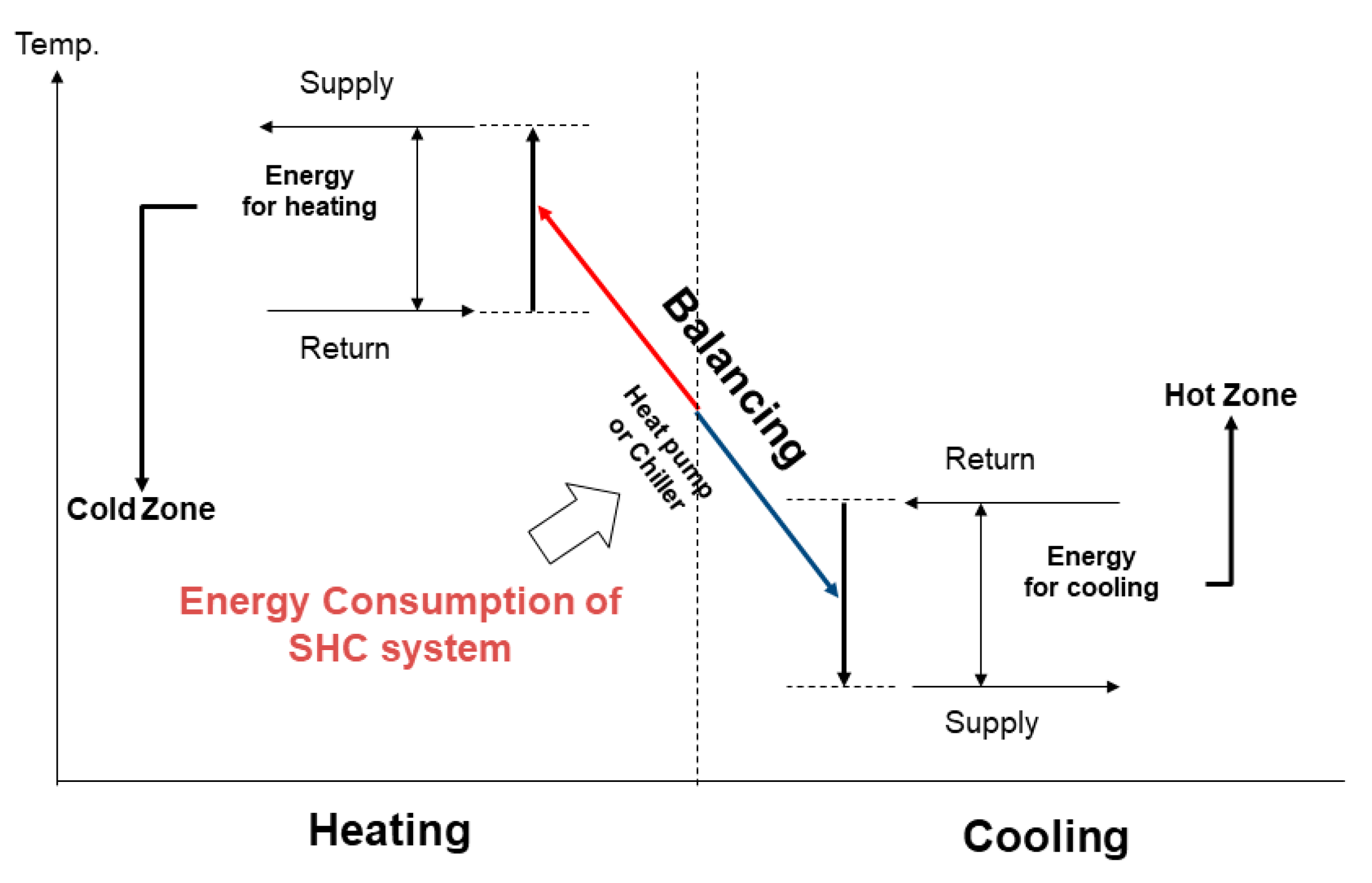
2.1. Simultaneous Heating and Cooling System (SHCs)

Simultaneous heating and cooling is a concept that recovers the heat inside a building to the maximum limit and uses it for heating or domestic hot water that requires heat in the building. Unlike the general system that removes each separately, even when heating and cooling loads occur simultaneously (Figure 1), it has the advantage of performing both heating and cooling with one operation of the refrigeration device (Figure 2). This concept is particularly advantageous in glazed buildings and cold climate areas, where large buildings generate a large amount of internal heat throughout the year.
As a general scenario when the SHC is considered, there is a case where a large amount of internal heat is generated in a building. In this case, cooling the building by applying an air economizer cycle can be applied. However, if this method is applied, almost all of the air is brought in from the outside; thus, a filter that can screen pollutants or toxic substances should be considered. Additionally, because the coil can freeze in winter, an alternative such as heat exchange using an antifreeze is required. In general, in a building with simultaneous heating and cooling, cooling the hot zone is possible, but heating the cold zone is impossible. Moreover, it cannot be performed if an air handling unit (AHU) is not installed. However, SHCs can be applied with or without the AHU and can simultaneously perform heating and cooling in a building to achieve significant energy savings.
The American Society of Heating, Refrigerating and Air-Conditioning Engineers (ASHRAE) defines balanced heat recovery as cooling by extracting heat from the hot zone and heating by supplying the extracted heat to the cold zone [3]. According to this concept, the original load removal behavior expected for SHCs is to remove as much as the amount that occurs when heating and cooling loads occur simultaneously. Therefore, in SHCs, a heat pump that can simultaneously produce heating and cooling energy should be used as a heat source device.
Sarkar et al. suggested the possibility of simultaneously providing both heating and cooling of a building and hot water [4]. Since then, research on SHCs has been conducted by developing a system with a new configuration and verifying the energy-saving efficiency. The mechanical efficiency was mainly analyzed experimentally under the conditions set in the standard ([5,6,7]), and energy efficiency was often analyzed by the simulation to consider various load conditions ([1,8,9,10,11,12,13]), which was also carried out as an experiment [14]. Additionally, exergy analysis was performed [15]. Studies on system composition have been actively conducted; however, it was inferred that existing methods were borrowed for capacity design and operation plans.
SHCs remove the load that occurs when heating and cooling loads occur simultaneously. Therefore, it is necessary to apply a refrigeration device with an evaporator capable of producing cooling energy and a condenser capable of producing heating energy concurrently, that is, a heat pump. A direct expansion system using air as an auxiliary heat source is an example of a system that performs SHC ([5,14]). If heat storage tanks are applied between the heat pump and hot/cold zone, the heating and cooling energy remaining in the heat storage tanks can be regarded as the heat storage temperature. For a heat storage tank with insufficient energy, the energy between the heat storage tanks can be balanced with a water-to-water heat pump. Using this method, additional load removal is expected with the stored heating and cooling energy even when no load is generated simultaneously ([1,6,7,8,9,10,12,13,15]). Although the initial cost of the heat storage tank is added, a heat pump that does not require continuous control can be used, and the overall cost can be reduced because of energy savings during operation. Ideally, if the capacities of the heat pump and heat storage tank can be designed, most of the cooling or heating loads can be removed using SHCs. If the load is different, it is inevitable to apply a free balancing source like air or geothermal. However, because the COP when using a balancing source is generally lower than that of water-to-water, it is necessary to maximize the efficiency of the entire system to perform the SHC using water-to-water.

2.2. Energy Consumption Analysis of SHCs

In this section, the load removal and energy consumption derivation methods of SHCs are proposed when the room temperature is set as the limit of the comfort range (general) and when the LB method is applied to arbitrarily balance the load to the maximum by changing the indoor set temperature (LB). In this study, a static state is assumed to be calculated in a simple form, whose factors mainly affect the LB. It is assumed that the capacity setting and control of the system are performed ideally and that all external environmental factors are known. It is revealed that there is a difference from the actual system owing to these limitations.
Generally, the energy consumption ( E ) for removing the load (Q) can be expressed by Equation (1). Accordingly, the cooling energy consumption (EC) for removing the cooling load ( Q C , +) and the heating energy consumption (EH) to remove the heating load (QH, −) can also be expressed by Equation (2) and Equation (3), respectively. The cooling COP ( C O P C ) and heating COP ( C O P H ) depend on the type of equipment, heat source, and refrigerant used:
E = Q C O P
E C = Q C C O P C
E H = Q H C O P H
When the cooling and heating systems are separated, the energy consumed is equal to the sum of the energy when the cooling and heating loads are removed. However, the energy input for simultaneous heating and cooling (ES) is the same as E C and EH as expressed in Equation (4). That is, QC and QH that can be removed by ES have the following relationship according to the cooling and heating COPs of simultaneous heating and cooling ( C O P C , S and C O P H , S ), as expressed in Equation (5):
E S = E C = E H
Q C = α Q H   ( w h e r e ,   α = C O P C , S C O P H , S )  

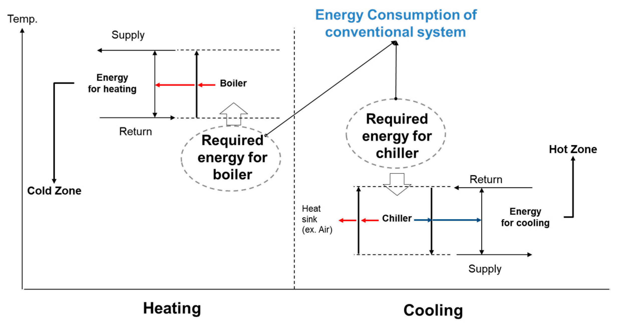
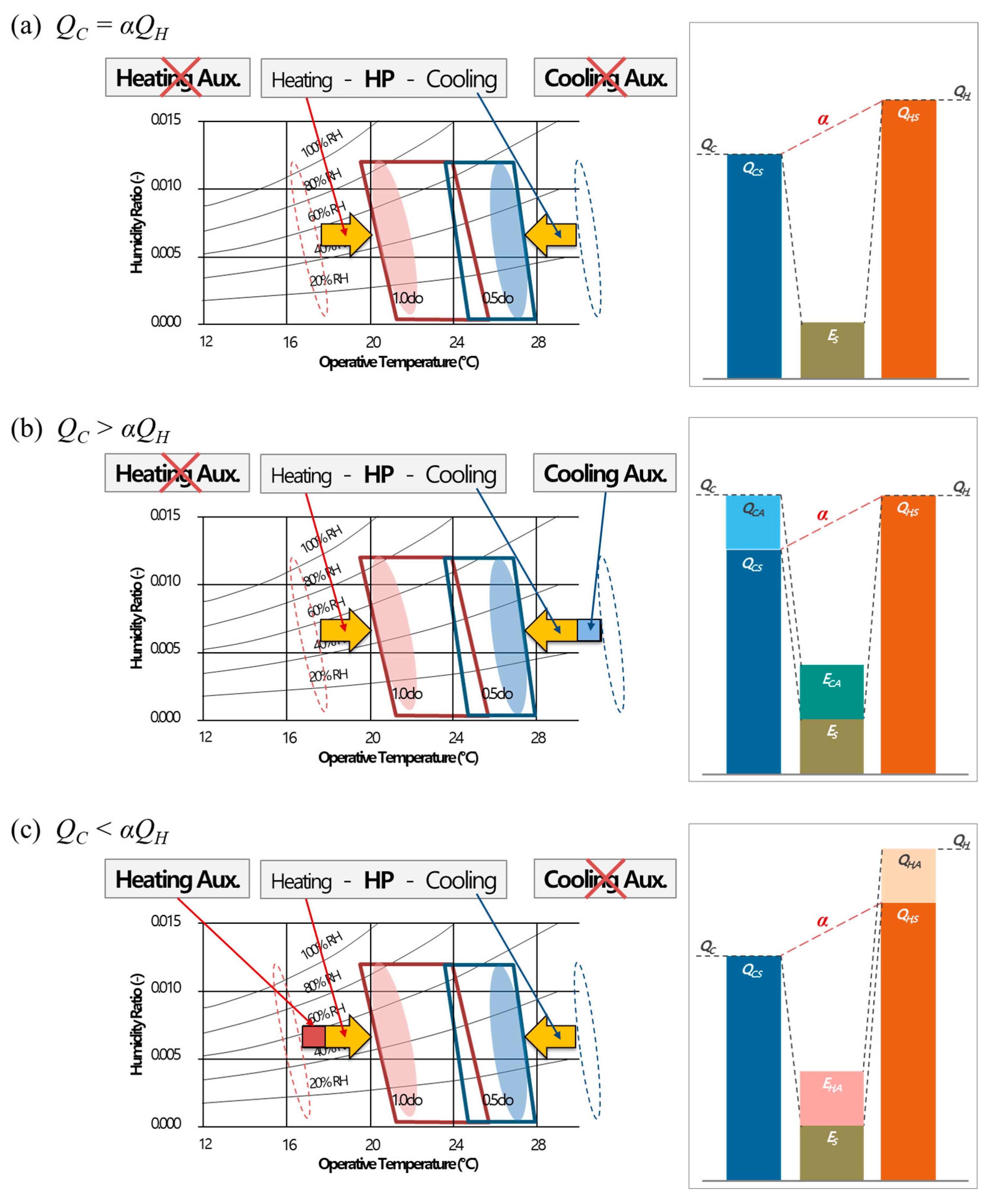
2.2.1. Energy Consumption of SHCs without Load Balancing (General)

In this section, the energy consumption was derived when Q C and Q H were minimized by setting the indoor temperature as the boundary of the comfort range to reduce energy. In this case, the total energy consumed is denoted as EG.
In the case of Q C = α Q H , all loads can be removed by the SHC without an auxiliary heat source. In this case, EG is equal to E S . Because ES is equal to EC and EH, Equation (6) can be derived:
E G = E S = E C = Q C C O P C , S = E H = Q H C O P H , S
However, Q C and α Q H were rarely the same. Even if the application of SHCs is designed in advance, the above case rarely occurs. When Q C and α Q H are not the same, the room temperature deviates from the range that satisfies the comfort of the occupants only with the SHC. The untreated load must be removed using an auxiliary heat source to bring the room temperature into the comfortable range.
In the case of Q C > α Q H , EG is equal to the sum of E S and EC,A as expressed in Equation (7). EC,A is the energy consumed when an auxiliary heat source is applied to remove a load that cannot be removed by the SHC( Q C , A ) . E S is the same as EH as expressed in Equation (8):
E G = E S + E C , A
E S = E H = Q H C O P H , S  
E C , A can be derived from Q C , A and cooling efficiency when the auxiliary heat source is applied ( C O P C , A ). QC,A is the value obtained by subtracting the load removed by the SHC (QC,S) from QC. QC,S is determined as the product of ES and C O P C , S . E C , A can be derived as expressed in Equation (9).
Here, E G can be summarized as Equation (10) through the above process:
E C , A = Q C , A C O P C , A = Q C Q C , S C O P C , A = Q C C O P C , S E S C O P C , A = Q C C O P C , S Q H C O P H , S C O P C , A = Q C α Q H C O P C , A
E G = E S + E C , A = Q H C O P H , S + Q C α Q H C O P C , A
In the case of Q C < α Q H , the energy consumed when an auxiliary heat source is applied (EH,A) and the total energy consumed ( E G ) can be derived in the same manner as in Equations (11) and (12):
E H , A = Q H + 1 α Q C C O P H , A
E G = E S + E H , A = Q C C O P C , S + Q H + 1 α Q C C O P H , A
The formulae for these three cases are shown schematically in Figure 3. The comfort zone was redraw based on reference [16]. The heating COP for the SHCs was assumed to be 5, and the cooling COP was assumed to be 4, which considered the theoretical difference of 1 between the heating COP and cooling COP during SHC. Additionally, if there are considerations for efficiency, such as applying thermal storage tanks or radiant heating and cooling [17], the COP can be sufficiently achieved. When an auxiliary heat source was applied, COP 1 was applied for both heating and cooling. The efficiency is lower in the case of using a boiler for heating but higher in a general heat pump. However, because the efficiency of the SHC is higher than when an auxiliary heat source is used, a difference is observed in the COP. In all cases, the indoor temperature was set at the boundary of the comfort range. When QC and α Q H are the same, all loads are handled by the SHC. However, in other cases, an auxiliary heat source was used to match the set temperature. Additionally, when the auxiliary heat source was used, the load removed was relatively small compared to the energy used for the SHC.

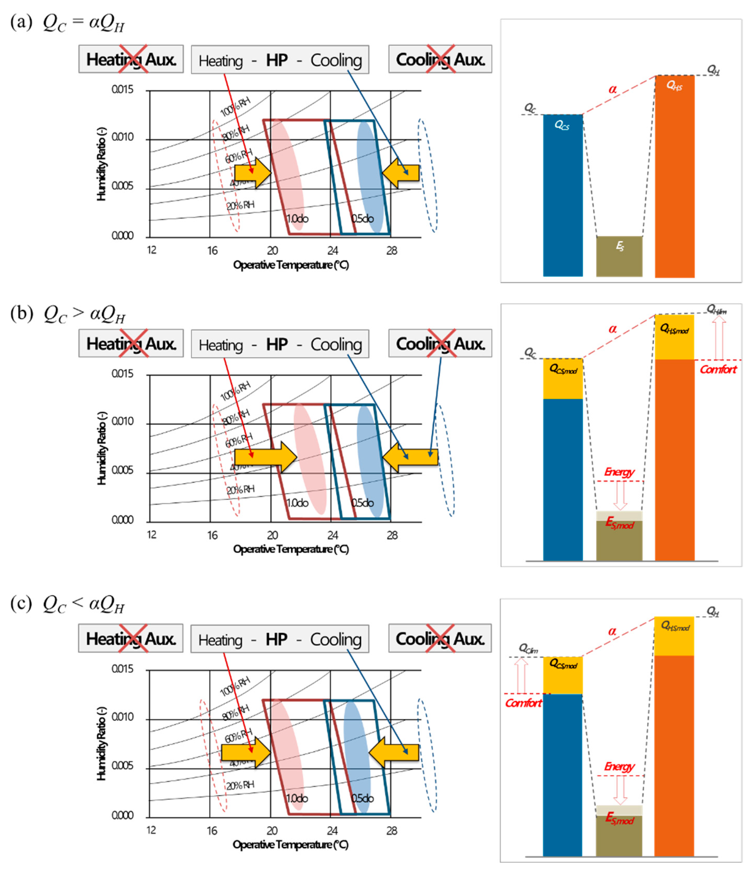
2.2.2. Energy Consumption of the SHCs with Load Balancing (LB)

In the case of Q C α Q H , SHC with LB changes the cooling or heating load within the comfort range so that it does not consume more energy than the general method to create state Q C α Q H . Changing the indoor set temperature within the comfort range implies that the room temperature should not exceed the allowable range. Therefore, the additional energy ( E S , a d d ) supplied for the SHC should not be greater than the difference between the energy for supplying/removing as much heat as possible within the allowable room temperature with the SHC ( E S , l i m ) and ES as expressed in Equation (13):
E S , a d d E S , l i m E S
Here, E S , a d d is defined as the additional energy supplied to remove as much heat as possible within the allowable room temperature by SHC ( E S , C , a d d ) or the additional energy supplied to supply as much heat as possible within the allowable room temperature by balancing ( E S , H , a d d ). First, E S , C , a d d should not be greater than the difference between the limit cooling energy ( E S , C , l i m ) and ES. E S , C , l i m is the energy required to remove the cooling load based on the allowable limit set temperature (e.g., 23 °C) within the comfort range ( Q C , l i m ). Q C , l i m can be derived using Equation (14):
Q C , l i m = K C A C ( T O T C , s e t , l i m ) + Q C , s o l + 1000 3600 N C V C ρ c p ( T O T C , s e t , l i m ) + Q C , i n t
By arranging the above equation, E S , C , a d d can be derived as Equation (15):
E S , C , a d d Q C , l i m Q C C O P C , S
Q H , l i m and E S , H , a d d can also be derived as Equations (16) and (17) in the same manner:
Q H , lim = K H A H ( T O T H , set , lim ) + Q H , sol + 1000 3600 N H V H ρ c p ( T O T H , set , lim ) + Q H , int
E S , H , a d d Q H , l i m + Q H C O P H , S
To avoid using more energy compared to the general method, E S , a d d should not exceed the energy when the auxiliary heat source is applied in the general method:
E S , a d d E C , A   a n d   E S , a d d E H , A  
In other words, in the case of Q C > α Q H , QC,A remains, in which case ES,add must not exceed EC,A. Additionally, in the case of Q C < α Q H , QH,A remains, and again ES,add must not exceed EH,A. EC,A and E H , A are in (10) and (12), respectively. Applying this to Equation (18) and rearranging it, Equation (19) can be derived:
E S , a d d Q C α Q H C O P C , A   a n d   E S , a d d Q H 1 α Q C C O P H , A
Considering all the ranges of Equations (15), (18) and (19), the limit value of energy that can be additionally input for the SHC ( E S , a d d , l i m ) can be summarized as follows:
E S , a d d , l i m = min ( Q C , l i m Q C C O P C , S , Q H , l i m + Q H C O P H , S , Q C α Q H C O P C , A , Q H 1 α Q C C O P H , A )  
The total energy consumption (EL) is the same as the general method for Q C = α Q H , so it is derived using Equation (6). In the case of Q C > α Q H , it is equal to the sum of the modified value of the energy consumed in the SHC ( E S , m o d ) and the modified value of the energy consumed when the auxiliary heat source is applied ( E C , A , m o d ). E S , m o d is equal to the sum of ES and E S , a d d , l i m , and E C , A , m o d is derived as the ratio of the modified value of the load to be removed as an auxiliary heat source ( Q C , A , m o d ) and the efficiency of the auxiliary heat source (COPC,A). Q C , A , m o d are the loads that cannot be removed by E S , m o d among the total loads. That is, it can be derived by subtracting the load that can be removed by the SHC ( Q C , S , m o d ) from the loads generated in the zone (in this case, the cooling load, Q C ). Q C , S , m o d can be derived by multiplying E S , m o d by C O P C , S . Here, when the set room temperature is changed, Q C , A , m o d may be greater than QC and have a negative value. In this case, Q C , A , m o d were set to 0.
When Q C > α Q H and Q C , A , m o d is equal to or greater than 0, E L can be expressed as Equation (21):
E L = E S , m o d + E C , A , m o d = ( E S + E S , a d d , l i m ) + Q C C O P C , S ( E S + E S , a d d , l i m ) C O P C , A   = Q C + ( Q H C O P H , S + E S . a d d . l i m ) ( C O P C , A + C O P C , S ) C O P C , A
When Q C < α Q H and Q H , A , m o d is equal to or less than 0, E L can be expressed as Equation (22):
E L = E S , m o d + E H , A , m o d = ( E S + E S , a d d , l i m ) + Q H C O P H , S ( E S + E S , a d d , l i m ) C O P H , A   = Q H + ( Q C C O P C , S + E S . a d d . l i m ) ( C O P H , A C O P H , S ) C O P H , A
The limit set temperature that can be achieved by the SHC ( T C , s e t , l i m , T H , s e t , l i m ) can be summarized by Equation (23) and Equation (24), respectively. If this temperature is outside the set temperature range, for example, when the cooling set temperature is equal to or greater than 28 °C or the heating set temperature is equal to or less than 18 °C, the residual load must be removed using an auxiliary heat source:
T C , s e t , l i m = T O Q C , S , m o d Q C , s o l Q C , i n t K C A C + 1000 3600 N C V C ρ c p
T H , s e t , l i m = T O Q H , S , m o d Q H , s o l Q H , i n t K H A H + 1000 3600 N H V H ρ c p
Figure 4 shows the set room temperature in the comfort zone, load removal pattern, and energy consumption when proposed LB method are applied. When the LB method is applied, the set temperature can be moved to the inside of the comfort zone, and energy can be saved.

2.3. General Method vs. Load Balancing Method

As described in the previous section, the formula was derived assuming that the capacity and control of the system were performed ideally, and all environmental factors such as the external temperature and internal heat were known. In particular, the limit set temperature that can be achieved by the SHC was also derived at intervals of 1 s. That is, it is not consistent with the actual situation in which the capacity design, control, and delay caused by the capacity must be considered. However, because the ideal amount of energy consumption can be expressed, the energy saving for a specific period can be expressed mathematically by slightly restricting the environmental factors. In addition, the factors affecting energy consumption were analyzed.
Therefore, as a second method, the load per second was derived at multiple set temperatures within the comfortable range through simulation considering the environmental factors and the energy in the case of performing SHC when the derived values of the heating and cooling loads per second were most similar.

2.3.1. Energy Saving When Using the LB Method

Energy savings can be obtained from the difference between the energy consumption when the general method is applied (EG) and the energy consumption when the LB method is applied (EL). First, in the case of Q C = α Q H , both EG and E L are equal to ES. However, in the case of Q C = α Q H , the energy savings when LB is applied can be summarized as Equation (25):
E G E L = ( Q H C O P H , S + Q C α Q H C O P C , A ) ( Q C + ( Q H C O P H , S + E S . a d d . l i m ) ( C O P C , A + C O P C , S ) C O P C , A ) = E S . a d d . l i m C O P C , S C O P C , A C O P C , A  
When Q C < α Q H , the energy savings when LB is applied can be expressed by Equation (26):
E G E L   = ( Q C C O P C , S + Q H + 1 α Q C C O P H , A ) ( Q H + ( Q C C O P C , S + E S . a d d . l i m ) ( C O P H , A C O P H , S ) C O P H , A ) = E S . a d d . l i m C O P H , S C O P H , A C O P H , A  
That is, the energy that can be saved by LB is proportional to the energy limit that can be additionally input to the SHC and is proportional to the ratio of the COP difference between the SHC and auxiliary heat source and the auxiliary heat source COP. That is, as more energy is input to the SHC or the auxiliary heat source COP is smaller than the SHC COP, the energy savings are greater.
To confirm the energy saving according to the application of LB, various cases in which the heating and cooling loads occur simultaneously were established, and simulations were performed. First, three heating loads were derived by setting the set temperature to 18 °C, 20 °C, and 22 °C. The three cooling loads were also derived by setting the set temperature to 28 °C, 26 °C, and 24 °C. These loads were combined as Case 1-1 (heating set temperature of 18 °C, cooling set temperature of 28 °C), Case 1-2 (heating set temperature of 20 °C, cooling set temperature of 26 °C), and Case 1-3 (heating set temperature of 22 °C cooling set temperature of 24 °C), and the load removal amount and energy consumption were calculated considering the relationship between the cooling COP and heating COP (Table 1). Further, to confirm the degree of energy saving according to the COP, various cooling and heating COPs were set in the most representative Case 1-2 (Table 2), and the results were derived and analyzed.

2.3.2. Energy Saving When Set Temperature Changes in Real Time

When LB was applied, the set room temperature was changed to balance the load. To simulate this situation, the load profile of cooling and heating at various set temperatures within the actual comfort range was derived, and the energy consumption when balancing between the loads that can remove the most load using the SHC was calculated.
In the same manner as described in Section 2.3.1, each case, Case 2-1 (heating set temperature of 18 °C, cooling set temperature of 28 °C), Case 2-2 (heating set temperature of 20 °C, cooling set temperature of 26 °C), Case 2-3 (heating set temperature of 22 °C, cooling set temperature of 24 °C), and the load removal amount and energy consumption were calculated considering the relationship between the cooling COP and heating COP [18]. In Case 2-4, as mentioned previously, the amount of load that can be removed by the SHC at each time step is maximized to simulate LB. These cases are summarized in Table 3.

2.3.3. Simulation Condition

To compare the load removal pattern and energy consumption when the COP is considered and when it is not considered for the general and LB methods derived above, loads of the hot and cold zones were derived through simulation. The target room consisted of a hot zone (e.g., server room) where internal loads always occurred, and a cold zone where heating loads occurred in winter. The winter weather data of Seoul were used so that the heating and cooling loads could occur simultaneously in the buildings, including these zones. The load was derived by TRNSYS [19] by setting the set temperature of the hot zone to 28 °C, 26 °C, and 24 °C and the set temperatures of the cold zone to 18 °C, 20 °C, and 22 °C. The details of the building information are presented in Table 4.
In the method described in Section 2.3.1, the thermal transmittance coefficient for calculating the transmittance load, excluding outside convection, was calculated as an area-weighted average, and 0.23 W/m2K was applied to the hot zone without a window, whereas 0.51 W/m2K was applied to the cold zone with a window. The outside surface temperature was calculated as the area-weighted average of the outside surface temperature of each side for the entire period, −1.32 °C for the hot zone and −1.87 °C for the cold zone. The window had a transmittance of 0.15 and an area of 20.87 m2, and the solar load in the cold zone with the window was input as 22.3 W/m2. Only the equipment heat of the hot zone was considered as the internal load. In an actual situation, more factors, such as ventilation and human loads, should be considered. However, in this study, the total load was important. Thus, the factors that generate the load were simplified. The load calculation was performed by placing the solar load, internal load, an area-weighted average of the outside surface temperature, room set temperature, area of each surface, and thermal transmittance and area excluding the outside convective coefficient into Equations (14) and (16). The result is derived as W, which corresponds to the average load over the entire period. Therefore, when calculating the total load by multiplying the total time, it should be derived similar to the total load derived through TRNSYS, and the total energy is derived assuming that the capacity of the heat storage tank is ideally designed for this period.
In the method described in Section 2.3.2, the load obtained from the TRNSYS simulation result was utilized by applying the contents in Table 4. The total load is derived similarly to the method described in Section 2.3.1, and the total amount of energy consumed is larger than that of the method described in Section 2.3.1, because the ratio of the load removed by the SHC is reduced owing to the absence of a heat storage tank.

3. Results and Discussion

In this section, the load removal amount and energy consumption according to the application of LB were compared and analyzed using the two energy savings deduction methods discussed in Section 2. The SHC COP, which is observed to affect energy consumption for both methods, was changed, and the degree of influence was analyzed. Thus, the energy that can be saved when LB is theoretically applied is derived, and its feasibility is studied.

3.1. Energy Saving When Using the LB Method

The loads derived from the hot and cold zones for each set of temperatures are summarized in Table 5. As mentioned previously, the loads are derived as the average value (W) of the entire period, and the total amount of load can be derived in kJ units by summing it for the entire period. The load removal amount and energy consumption according to whether LB was applied for each set temperature are summarized in Table 6 when the SHC was performed assuming a heating COP of 5, cooling COP of 4, and COP of 1 when using an auxiliary heat source. Table 7 and Figure 5 summarize the load removal amount and energy consumption according to the SHC COP for the representative set temperatures of 26 °C and 20 °C.
The greater the difference between the outside air temperature and the set-point temperature, the greater the load. In Case 1-1, it was determined that the set temperature of the cold zone increased by 4 °C, and the thermal comfort increased compared to the general method. As the heating load removal ratio of the SHC increased, the total energy was reduced by 192,752 kJ, as fewer heating auxiliaries with low COP were used. In Case 1-2, the set temperature of the cold zone increased by 2 °C, which was observed to have increased thermal comfort compared to the general method, and the total energy was reduced by 96,376 kJ for the same reason as in Case 1-1. In Case 1-3, there was no change in energy consumption before and after LB, possibly because the indoor temperature was set to the most comfortable temperature previously determined. That is, the more the set point is set closer to the boundary of the comfort zone, the greater the energy savings when using the LB method compared to the general method. When the temperature is set as the boundary of the comfort range in a building with a set point temperature constraint (e.g., a public institution), it is deduced that both comfort increase and energy saving can be satisfied if the SHCs and LB methods are applied.
The calculation for a wide range of COPs was performed to show how much energy can be saved according to the change in cooling COP and heating COP. When various cooling and heating COPs are applied to Case 1-2, the amount of energy saving is determined according to Equation (25). That is, as the efficiency of the SHC increases more than the efficiency when the auxiliary heat source is applied, it can be confirmed that the amount of energy saving increases. However, if the difference between the COPs is larger than a certain level, as in 1-2-9, Q C , A , m o d becomes 0 and does not follow Equation (25). Energy is saved compared to the general method, but the amount of energy saved is reduced compared to 1-2-8. However, it is confirmed that the set room temperature can be lowered by approximately −0.3 °C by removing the cooling load.

3.2. Energy Saving When Set Temperature Changes in Real Time

The loads derived from the hot and cold zones for each set temperature are summarized in Table 8. When the SHC was performed assuming a heating COP of 5, cooling COP of 4, and COP of 1 when using an auxiliary heat source, the load removal amount and energy consumption according to whether LB was applied for each set temperature are summarized in Table 9. Table 10 presents the number and ratio of the set temperatures in Case 2-4. Since timestep is 1 s, number is the same as expressing the total time the temperature is set in seconds, and ratio is the ratio of the time the temperature is set to the total time.
The total amount of load derived by TRNSYS by modeling the hot and cold zones is slightly different from the load derived by the calculation in Section 3.1. In Section 3.1, when calculating the cooling load, the wall heat gain due to solar radiation was not considered, and when calculating the heating load, it was deduced that there were various error factors, such as calculating the sun incident on the frame as the transmittance of the glass. However, because the difference is within 5%, it is not expected to significantly affect the calculation of the energy required.
In Case 2-1, the energy consumed by the SHC was 21,631 kJ smaller than that of the general method in Case 1-1. However, 155,125 kJ of energy using an auxiliary cooling heat source and 92,056 kJ of energy using an auxiliary heating source were added. A total of 225,549 kJ of additional energy was used, and the error was approximately 60%. As mentioned previously, in Section 3.1, it is assumed that the heat storage tank is equipped with an ideal capacity for the period, and in Section 3.2, it is deduced that the heat storage tank is not considered. This seems to have affected the 62% difference between Case 2-2 and Case 1-2, and the 63% difference between Case 2-3 and Case 1-3.
However, in Case 2-4, the total energy was 618,573 kJ, and although the heat storage tank was not applied, less energy was used than in Cases 1−2 and Cases 1−3. This shows that a large amount of energy can be saved if the LB is used appropriately by predicting the load in the room. Additionally, the heating preset temperature reached a maximum of 22 °C, and the cooling preset temperature was approximately 40%, including 24 °C and 26 °C; thus, it can be deduced that thermal comfort is also improved.

4. Conclusions

In this study, when applied to a simultaneous heating and cooling system, the energy saving potential that can be obtained by changing the indoor set temperature within a comfortable range was derived. To achieve this, a theoretical study was conducted to derive the factors affecting energy consumption and simulations were performed to verify the theory. The conclusions of this study are summarized as follows:
(1)
Simultaneous cooling and heating systems using heat pumps can be effectively utilized in buildings where heating and cooling loads occur simultaneously. When combined with a heat storage tank, more loads can be removed, even when loads do not occur simultaneously. An auxiliary heat source such as an air source can be applied when the amount of load is different. However, the efficiency is generally lower than that of simultaneous heating and cooling using a water-to-water heat pump. Therefore, maximizing simultaneous heating and cooling can improve the overall system efficiency.
(2)
The energy saved by the LB method is proportional to the energy limit that can be additionally input to the simultaneous heating and cooling, and the ratio of the COP difference between the simultaneous heating and cooling and the auxiliary and COP of the auxiliary heat source. That is when more energy is input to the simultaneous heating and cooling, or the auxiliary heat source COP is smaller than the simultaneous heating and cooling COP, the energy saving is greater.
(3)
The LB method is advantageous, not only in terms of energy savings, but also in terms of comfort by removing more loads. In particular, in the case of setting the set point at the boundary of the comfort zone, it was found that energy savings were greater when the LB method was used than when the general method was used. Thus, when the temperature is set as the boundary of the comfort range in a building (e.g., a public institution) with restrictions on the set-point temperature, both the comfort increase and energy saving can be satisfied if the simultaneous heating and cooling system and LB methods are applied.
(4)
When a heat storage tank with an ideal capacity is installed, approximately 60% of the energy can be saved compared to the case where the heat storage tank is not installed. Additionally, in the case of LB, by changing the set room temperature of both the hot and cold zones in real-time by predicting the indoor load, more energy can be saved than in the LB method, which changes only one load.
In this study, only temperature change was considered as a factor affecting comfort; in future studies, it is necessary to consider the influence of various comfort factors such as humidity and radiant temperature. Based on this, it is necessary to study the relationship between comfort indicators, such as PMV and PPD.

Author Contributions

Conceptualization, D.-U.S. and C.-H.J.; methodology, D.-U.S.; software, D.-U.S.; validation, D.-U.S. and C.-H.J.; formal analysis, D.-U.S.; investigation, D.-U.S.; resources, D.-U.S.; data curation, D.-U.S.; writing—original draft preparation, D.-U.S.; writing—review and editing, C.-H.J.; visualization, D.-U.S.; supervision, C.-H.J.; project administration, D.-U.S.; funding acquisition, D.-U.S. All authors have read and agreed to the published version of the manuscript.

Funding

This work was supported by the National Research Foundation of Korea (NRF) grant funded by the Korea government (MSIT) (No. 2020R1G1A1099594).

Institutional Review Board Statement

Not applicable.

Informed Consent Statement

Not applicable.

Conflicts of Interest

The authors declare no conflict of interest.

Nomenclature

Latin letters:
ASurface area (m2)
COPCoefficient of performance (−)
EConsumed energy (W)
KK-value (W/m2K)
LBLoad Balancing
NNumber of ventilation (1/h)
Q Thermal load (W)
SHCSimultaneous Heating and Cooling
TTemperature (°C)
VVolume (m3)
cSpecific heat (kJ/kgK)
Greek letters:
α Ratio of COPs (−)
ρ Density (kg/m3)
Subscripts:
AAuxiliary heat source
CCooling
GGeneral
HHeating
LLoad Balancing
OOutside
SSimultaneous heating and cooling
addAdditional
intInternal
limlimit
modModified
pStatic pressure
setSet point
solSolar

References

  1. Byrne, P.; Miriel, J.; Lénat, Y. Design and simulation of a heat pump for simultaneous heating and cooling using HFC or CO2 as a working fluid. Int. J. Refrig. 2009, 32, 1711–1723. [Google Scholar] [CrossRef] [Green Version]
  2. Shin, D.U.; Leigh, T.H.; Joe, G.S.; Kim, M.G.; Yeo, M.S.; Kim, K.W. Energy performance of balanced heat recovery systems with load-balancing. Energy Procedia 2015, 78, 2445–2451. [Google Scholar] [CrossRef] [Green Version]
  3. Chapter 9 Applied heat pump and heat recovery systems. In ASHRAE Handbook—HVAC Systems and Equipment; ASHRAE: Peachtree Corners, GA, USA, 2020.
  4. Sarkar, J.; Bhattacharyya, S.; Gopal, M.R. Simulation of a transcritical CO2 heat pump cycle for simultaneous cooling and heating applications. Int. J. Refrig. 2006, 29, 735–743. [Google Scholar] [CrossRef]
  5. Kang, H.; Joo, Y.; Chung, H.; Kim, Y.; Choi, J. Experimental study on the performance of a simultaneous heating and cooling multi-heat pump with the variation of operation mode. Int. J. Refrig. 2009, 32, 1452–1459. [Google Scholar] [CrossRef]
  6. Byrne, P.; Miriel, J.; Lénat, Y. Experimental study of an air-source heat pump for simultaneous heating and cooling—Part 1: Basic concepts and performance verification. Appl. Energy 2011, 88, 1841–1847. [Google Scholar] [CrossRef] [Green Version]
  7. Byrne, P.; Miriel, J.; Lénat, Y. Experimental study of an air-source heat pump for simultaneous heating and cooling—Part 2: Dynamic behaviour and two-phase thermosiphon defrosting technique. Appl. Energy 2011, 88, 3072–3078. [Google Scholar] [CrossRef] [Green Version]
  8. Byrne, P.; Miriel, J.; Lénat, Y. Modelling and simulation of a heat pump for simultaneous heating and cooling. Build. Simul. 2012, 5, 219–232. [Google Scholar] [CrossRef] [Green Version]
  9. Ghoubali, R.; Byrne, P.; Miriel, J.; Bazantay, F. Study of a heat pump for simultaneous heating and cooling working with R290 or R1234yf and coupled to a building. ASHRAE Trans. 2013, 119, 1–8. [Google Scholar]
  10. Ghoubali, R.; Byrne, P.; Miriel, J.; Bazantay, F. Simulation study of a heat pump for simultaneous heating and cooling coupled to buildings. Energy Build. 2014, 72, 141–149. [Google Scholar] [CrossRef] [Green Version]
  11. Fricker, J.; Zoughaib, A. Simultaneous heating and cooling production devices composed by reverse cycle systems under variable loads. Int. J. Refrig. 2015, 55, 1–16. [Google Scholar] [CrossRef]
  12. Shin, D.U.; Ryu, S.R.; Kim, K.W. Simultaneous heating and cooling system with thermal storage tanks considering energy efficiency and operation method of the system. Energy Build. 2019, 205, 109518. [Google Scholar] [CrossRef]
  13. Diaby, A.T.; Byrne, P.; Mare, T. Simulation of heat pumps for simultaneous heating and cooling using CO2. Int. J. Refrig. 2019, 106, 616–627. [Google Scholar] [CrossRef]
  14. Joo, Y.; Kang, H.; Ahn, J.; Lee, M.; Kim, Y. Performance characteristics of a simultaneous cooling and heating multi-heat pump at partial load conditions. Int. J. Refrig. 2011, 34, 893–901. [Google Scholar] [CrossRef]
  15. Byrne, P.; Ghoubali, R. Exergy analysis of heat pumps for simultaneous heating and cooling. Appl. Therm. Eng. 2019, 149, 414–424. [Google Scholar] [CrossRef]
  16. Standard 55. Thermal Environmental Conditions for Human Occupancy; ASHRAE: Peachtree Corners, GA, USA, 2017. [Google Scholar]
  17. Shin, D.U.; Leigh, T.H.; Joe, G.S.; Kim, M.G.; Yeo, M.S.; Kim, K.W. Energy performance of balanced heat recovery systems with different terminal systems. In Proceedings of the IBPSA Asia Conference 2014, Nagoya, Japan, 28–29 November 2014. [Google Scholar]
  18. Shin, D.U.; Lee, S.J.; Joe, G.S.; Park, S.J.; Yeo, M.S.; Kim, K.W. Development of evaluation method for Energy Balancing System in super-large complex buildings. In Proceedings of the ISES 2011 Solar World Congress, Kassel, Germany, 28 August–2 September 2011. [Google Scholar]
  19. Klein, S.A.; Beckman, W.A.; Mitchell, J.W.; Duffie, J.A.; Duffie, N.A.; Freeman, T.L.; Kummer, J.P. TRNSYS 17 A Transient System Simulation Program; University of Wisconsin-Madison: Madison, WI, USA, 2009. [Google Scholar]
Figure 1. Concept diagrams of a conventional system.
Energies 14 07691 g001
Figure 2. Concept diagrams of SHCs.
Energies 14 07691 g002
Figure 3. Energy consumption according to heating and cooling loads (general).
Energies 14 07691 g003
Figure 4. Energy consumption according to cooling and heating loads (LB).
Energies 14 07691 g004
Figure 5. Removed load and energy consumption (Cases 1−2-1~1−2-9).
Energies 14 07691 g005
Table 1. Cases for method written in Section 2.3.1.
CaseSet Temp. (°C)
Hot ZoneCold Zone
Case 1-12818
Case 1-22620
Case 1-32422
Table 2. Subcases of Case 1-2 for various heating and cooling COPs.
CaseSet Temp. (°C)
Heating COPCooling COP
Case 1-2-121
Case 1-2-232
Case 1-2-343
Case 1-2-454
Case 1-2-565
Case 1-2-676
Case 1-2-787
Case 1-2-898
Case 1-2-9109
Table 3. Cases for method written in Section 2.3.2.
CaseSet Temp. (°C)
Hot ZoneCold Zone
Case 2-12818
Case 2-22620
Case 2-32422
Case 2-428, 26, 2418, 20, 22
Table 4. Simulation input data.
ContentsDimensionInternal Load (W)Wall/Window Type
BuildingHot zone8.1 m(W) × 6 m(D) × 2.7 m(H)1840
(for all time)
-
Front wall: VirtualSurface
-
Back/Right/Left wall: EXT_WALL
-
Ceiling: CEILING
-
Floor: EXT_FLOOR
Cold zone8.1 m(W) × 3 m(D) × 2.7 m(H)0
-
Front wall: EXT_WINDOW1
-
Back wall: VirtualSurface
-
Right/Left wall: EXT_WALL
-
Ceiling: CEILING
-
Floor: EXT_FLOOR
Material
-
EXT_WALL: Plasterboard_12 mm (0.576 kJ/hmK), Fiberglass_66 mm (0.144 kJ/hmK),
-
Wood siding_9 mm (0.504 kJ/hmK)
-
EXT_WINDOW1: U-value 1.4 W/m2K, g-value 0.589
-
CEILING: Chilled Ceiling, Air layer (0.042 hm2K/kJ)
-
EXT_FLOOR: Cement mortar_40 mm (5.04 kJ/hmK), Lightweight concrete_40 mm (1.4 kJ/hmK), Polyurethane_100 mm (0.11 kJ/hmK), Concrete slab_210 mm (4.068 kJ/hmK)
LocationSeoul, Republic of KoreaPeriod1 month: from 21 January to 10 February
(Timestep: 1 s)
Table 5. Zone thermal load according to set point temperatures.
Hot ZoneCold Zone
Set temperature (°C)282624182022
Transmittance load (W)−1038−967−897−882−971−1060
Solar load (W)000707070
Internal load (W)184018401840000
Total load (W)802873943−812−901−990
Total amount of load (kJ)1,454,6631,583,1651,711,666−1,474,050−1,635,170−1,796,290
Table 6. Removed load and energy consumption (Cases 1−1~1−3).
Case GeneralLoad Balancing
Hot ZoneCold ZoneHot ZoneCold Zone
Case 1-1Set Temp. (°C)281828(0)22 (+4)
Load (kJ)1,454,663−1,474,0501,454,663 (0)−1,795,304 (−321,254)
SHC: 1,179,240
Aux.: 275,423
SHC: −1,474,050
Aux.: 0
SHC: 1,436,243
Aux.: 18,420
SHC: −1,795,304
Aux.: 0
Energy (kJ)570,233377,481 (−192,752)
SHC: 294,810 Aux.: 275,423SHC: 359,061 Aux.: 18,420
Case 1-2Set Temp. (°C)262026(0)22 (+2)
Load (kJ)1,583,165−1,635,1701,583,165 (0)−1,795,797 (−96,376)
SHC: 1,308,136
Aux.: 275,029
SHC: −1,635,170
Aux.: 0
SHC: 1,436,638
Aux.: 146,527
SHC: −1,795,797
Aux.: 0
Energy (kJ)602,063505,687 (−96,376)
SHC: 327,034 Aux.: 275,029SHC: 359,159 Aux.: 146,527
Case 1-3Set Temp. (°C)242224(0)22 (0)
Load (kJ)1,711,666−1,796,2901,711,666 (0)−1,796,290 (0)
SHC: 1,437,032
Aux.: 274,634
SHC: −1,796,290
Aux.: 0
SHC: 1,437,032
Aux.: 274,634
SHC: −1,796,290
Aux.: 0
Energy (kJ)633,892633,892 (0)
SHC: 359,258 Aux.: 275,029SHC: 359,258 Aux.: 274,634
Table 7. Removed load and energy consumption (Cases 1−2-1~1−2-9).
Case GeneralLoad Balancing
Hot ZoneCold ZoneHot ZoneCold Zone
Case 1-2-1
C O P H , S = 2
C O P C , S = 1
Set Temp. (°C)262026(0)22 (+2)
Load (kJ)1,583,165−1,635,1701,583,165 (0)−1,796,290 (−161,120)
SHC: 817,585
Aux.: 765,580
SHC: −1,635,170
Aux.: 0
SHC: 898,145
Aux.: 685,020
SHC: −1,796,290
Aux.: 0
Energy (kJ)1,583,1651,583,165 (0)
SHC: 817,585 Aux.: 765,580SHC: 898,145 Aux.: 685,020
Case 1-2-2
C O P H , S = 3
C O P C , S = 2
Set Temp. (°C)262026(0)22 (+2)
Load (kJ)1,583,165−1,635,1701,583,165 (0)−1,796,290 (−161,120)
SHC: 1,090,113
Aux.: 493,051
SHC: −1,635,170
Aux.: 0
SHC: 1,197,527
Aux.: 385,638
SHC: −1,796,290
Aux.: 0
Energy (kJ)1,038,108984,402 (−53,707)
SHC: 545,075 Aux.: 493,051SHC: 598,763 Aux.: 385,638
Case 1-2-3
C O P H , S = 4
C O P C , S = 3
Set Temp. (°C)262026(0)22 (+2)
Load (kJ)1,583,165−1,635,1701,583,165 (0)−1,796,290 (−161,120)
SHC: 1,226,378
Aux.: 356,787
SHC: −1,635,170
Aux.: 0
SHC: 1,347,218
Aux.: 235,947
SHC: −1,796,290
Aux.: 0
Energy (kJ)765,580685,020 (−80,560)
SHC: 408,793 Aux.: 356,787SHC: 449,073 Aux.: 235,947
Case 1-2-4
C O P H , S = 5
C O P C , S = 4
Set Temp. (°C)262026(0)22 (+2)
Load (kJ)1,583,165−1,635,1701,583,165 (0)−1,795,797 (−160,627)
SHC: 1,308,136
Aux.: 275,029
SHC: −1,635,170
Aux.: 0
SHC: 1,436,638
Aux.: 146,527
SHC: −1,795,797
Aux.: 0
Energy (kJ)602,063505,687 (−96,376)
SHC: 327.034 Aux.: 275,029SHC: 359,159 Aux.: 146,527
Case 1-2-5
C O P H , S = 6
C O P C , S = 5
Set Temp. (°C)262026(0)22 (+2)
Load (kJ)1,583,165−1,635,1701,583,165 (0)−1,789,372 (−154,202)
SHC: 1,362,642
Aux.: 220,523
SHC: −1,635,170
Aux.: 0
SHC: 1,491,143
Aux.: 92,022
SHC: −1,789,372
Aux.: 0
Energy (kJ)493,051390,250 (−102,801)
SHC: 272.528 Aux.: 220,523SHC: 298,229 Aux.: 92,022
Case 1-2-6
C O P H , S = 7
C O P C , S = 6
Set Temp. (°C)262026(0)22 (+2)
Load (kJ)1,583,165−1,635,1701,583,165 (0)−1,785,089 (−149,918)
SHC: 1,401,574
Aux.: 181,590
SHC: −1,635,170
Aux.: 0
SHC: 1,530,076
Aux.: 53,089
SHC: −1,785,089
Aux.: 0
Energy (kJ)415,186308,102 (−107,085)
SHC: 233.596 Aux.: 181,590SHC: 255,013 Aux.: 53,089
Case 1-2-7
C O P H , S = 8
C O P C , S = 7
Set Temp. (°C)262026(0)22 (+2)
Load (kJ)1,583,165−1,635,1701,583,165 (0)−1,782,029 (−146,859)
SHC: 1,430,774
Aux.: 152,391
SHC: −1,635,170
Aux.: 0
SHC: 1,559,275
Aux.: 23,889
SHC: −1,782,029
Aux.: 0
Energy (kJ)356,787246,643 (−110,144)
SHC: 204.396 Aux.: 152,391SHC: 222,754 Aux.: 23,889
Case 1-2-8
C O P C , S = 8
C O P H , S = 9
Set Temp. (°C)262026(0)22 (+2)
Load (kJ)1,583,165−1,635,1701,583,165 (0)−1,779,734 (−144,564)
SHC: 1,453,485
Aux.: 129,680
SHC: −1,635,170
Aux.: 0
SHC: 1,581,986
Aux.: 1,179
SHC: −1,779,734
Aux.: 0
Energy (kJ)311,366198,927 (−112,439)
SHC: 181.686 Aux.: 129,680SHC: 197,748 Aux.: 1,179
Case 1-2-9
C O P H , S = 10
C O P C , S = 9
Set Temp. (°C)262025.7(−0.3)22 (+2)
Load (kJ)1,583,165−1,635,1701,600,155 (0)−1,777,950 (−142,779)
SHC: 1,471,653
Aux.: 111,512
SHC: −1,635,170
Aux.: 0
SHC: 1,600,155
Aux.: 0
SHC: −1,777,950
Aux.: 0
Energy (kJ)275,029177,795 (−97,234)
SHC: 163,517 Aux.: 111,512SHC: 177,795 Aux.: 0
Table 8. Zone thermal load according to set point temperatures.
Hot ZoneCold Zone
Set temperature (°C)282624182022
Total amount of load (kJ)1,523,2631,656,2121,788,559−1,457,951−1,654,205−1,852,610
Difference between loads (%)1.11.23.14.74.64.5
Table 9. Removed load and energy consumption (Cases 2-1~2-4).
Case General
Hot ZoneCold Zone
Case 2-1Set Temp. (°C)2818
Load (kJ)1,523,263−1,457,951
SHC: 1,092,716
Aux.: 430,548
SHC: −1,365,894
Aux.: −92,056
Energy (kJ)795,783
SHC: 273,179 Cooling Aux.: 430,548 Heating Aux.: 92,056
Case 2-2Set Temp. (°C)2620
Load (kJ)1,656,212−1,654,205
SHC: 1,329,288
Aux.: 416,924
SHC: −1,549,110
Aux.: −105,095
Energy (kJ)831,841
SHC: 309,822 Cooling Aux.: 416,924 Heating Aux.: 105,0956
Case 2-3Set Temp. (°C)2422
Load (kJ)1,788,559−1,852,610
SHC: 1,386,166
Aux.: 402,393
SHC: −1,732,707
Aux.: −119,903
Energy (kJ)868,838
SHC: 346,541 Cooling Aux.: 402,393 Heating Aux.: 119,903
Case 2-4Set Temp. (°C)28, 26, 2418, 20, 22
Load (kJ)1,600,875−1,721,002
SHC: 1,351,652
Aux.: 249,223
SHC: −1,669,565
Aux.: −31,437
Energy (kJ)618,573
SHC: 337,913 Cooling Aux.: 249,223 Heating Aux.: 31,437
Table 10. Number and ratio of set temperature in Case 2-4.
Heating
Set Temperature (°C)
Number of
Settings
Ratio (%)Cooling
Set Temperature (°C)
Number of
Settings
Ratio (%)
18888629.382818,09059.82
2024438.0826499916.53
2218,91262.5424715223.65
Publisher’s Note: MDPI stays neutral with regard to jurisdictional claims in published maps and institutional affiliations.

