Abstract
In the geyser boiling mode, the working fluid state is divided into a boiling process and a quiet process, and the sodium-potassium (Na-K) alloy heat pipe can discontinuously transfer heat at each boiling. The overheating of the liquid working fluid at the bottom causes short-term boiling and forms slug bubble, the strong condensing ability quickly conducts heat from the evaporator section. And geyser boiling can occur before the working fluid forms continuous flow, so it transfers more heat at lower temperatures than natural convection cooling. In this study, the heat transfer process of a Na-K alloy heat pipe with forced convection cooling under different heating power was experimental studied. The geyser boiling mode can make the Na-K alloy heat pipe work below 650 °C and reduce the start-up time. In the process of geyser boiling, the heat transfer quantity was increased by the boiling frequency and the amount of vapor produced in a single boiling. The boiling temperature had no obvious change with the increased of heating power, and the condenser section temperature increased with the heating power.
1. Introduction
Heat pipes rely on the phase transformation of the working fluid to transfer heat by using latent heat. Therefore, heat pipes have high heat transfer performance [1], isothermal performance [2] and thermal response speed [3]. The working temperature of high temperature heat pipes is higher than 750 K. Sodium, potassium and other alkali metals are often used as working fluid for high temperature heat pipe because of their high boiling temperature, low saturation pressure, high latent heat of vaporization and high heat transfer performance. Alkali metal heat pipes have been used in many high temperature applications such as high temperature isothermal heater [4], thermometric calibration system [5,6], solar energy utilization system [7,8], residual heat removal system [9,10,11,12], high temperature thermal management [13,14,15] and so on. The alloy of suitable ratio of sodium and potassium is liquid at room temperature, so the sodium-potassium (Na-K) alloy heat pipe has great advantages in cold-start and working fluid filling. Na-K alloy was the first used as coolant in nuclear industry, Anderson et al. [16] proposed to replace pure metals such as sodium and potassium as high temperature heat pipe working fluid. The thermal properties and flow characteristics of Na-K (78% by mass of potassium) alloy were studied by Serizawa et al. [17] and Timothy et al. [18]. The results showed that the heat transfer performance of the alloy is better than sodium and potassium. The start-up performance of liquid metal heat pipes is very different from the low temperature heat pipes, the effect of compressibility must be considered at start-up stage because of the low pressure and low density of vapor. The continuous flow can be formed only after the working fluid reaches a certain temperature, then the vapor density and pressure increase significantly and the heat pipe can transfer heat effectively. Similar to other alkali metal heat pipes, the heat transfer limits such as sonic limit and viscosity limit also appear in the start-up process of Na-K alloy heat pipes. Na-K alloy heat pipes also have several advantages, different mass ratios of sodium and potassium can be selected according to the requirements of working temperature. Due to the melting point of the Na-K alloy is below room temperature when the mass fraction of potassium is between 46% and 89%. Therefore, there is no frozen limit at room temperature and it is beneficial to the manufacture of heat pipe such as the high temperature oscillating heat pipe [19], and there is no solidification limit, the working fluid will not solidify into solid state in the condenser section, avoid that the working fluid cannot return and the evaporator section dry burning.
At present, Na-K alloy heat pipes have been applied in many fields such as molten salt residual heat utilization system [20], high temperature cooling system [21] and so on. Working conditions have a great influence on the start-up heat transfer performance of Na-K alloy heat pipe. When the length of condenser section is too long, the working fluid is not easy to fill the whole heat pipe [22,23]. When the length of the condenser section is too small, the condenser amount of the working medium is small, which increases the gas pressure [23,24]. The inclination angle of heat pipe will affect the effective heating area of evaporator and the driving force of reflux liquid, and the most suitable inclination angle of Na-K alloy heat pipe is 55° [25]. The Na-K alloy heat pipe has been proved to be an effective high thermal conductivity element, the heat transfer ability and service temperature of Na-K alloy heat pipe are between those of sodium heat pipe and potassium heat pipe in full start state. Because the melting point of Na-K alloy is lower than room temperature, it is safer in working fluid filling and cold start process, so the Na-K alloy heat pipe is a kind of safer heat pipe which can replace sodium heat pipe. And there is no solidification phenomenon in geyser boiling. The geyser boiling is a kind of repeated process in which the working fluid suddenly boils and returns to calm.
In this article, Section 2 Literature review presents related works on the geyser boiling. Section 3 Experimental methods presents the equipment, experimental system and experimental method. Section 4 Results and discussions presents working process of Na-K alloy heat pipe and effects of heating power on geyser boiling process, heat pipe wall temperature distribution and heat transfer performance. Section 5 Conclusions presents the main conclusions in this study.
2. Literature Review
Noie et al. [26] studied the influence of the inclination angle on the heat transfer coefficient of the condenser under different liquid charge ratios. It was found that geyser boiling occurred when the liquid charge ratios is greater than 30%.
Emani et al. [27] studied the effects of liquid charge ratio, inclination and cooling water mass flow on the geyser boiling. It was found that when the inclination angle was reduced, the geyser period and the temperature fluctuation range were reduced, and the geyser boiling phenomenon disappeared when the inclination angle was less than 15°. The mass flow rate of the cooling water has little effect on the geyser boiling phenomenon.
Lin et al. [28] studied the influence of heating power, condenser temperature, liquid charge ratio and evaporator length on water and ethanol geyser boiling. The correlation equation of heat transfer coefficient in geyser boiling was proposed.
Wang et al. [29] presented a combined CFD/visualization study and used the VOF method to improve the Lee model. The improved model had better predictive performance, and the heat transfer behavior obtained was closer to the actual phenomenon in the visualization experiment.
Some literature studied how to suppress geyser boiling. Casarosa et al. [30] studied the influence of heating power and condenser pressure on geyser boiling. When the condenser pressure remained constant, the boiling frequency increased linearly with the increase of heating power. When the heating power was constant, increasing the condenser pressure reduced the geyser boiling, and even eliminated the geyser boiling.
Kujawska et al. [31] studied the geyser boiling phenomenon of heat pipes using nanofluids. It was found that nanofluids can reduce or even inhibit geyser boiling. The deposition of nanoparticles on the evaporator wall increases the number of nucleation points that can form vapor bubbles and prevents the formation of gas plugs.
Although most literatures hope to eliminate geyser boiling [32,33], some literatures have noticed that geyser boiling can be applied. Kuncoro et al. [34] studied the effects of temperature and pressure on the geyser boiling of water and R113. The study found that the temperature distribution inside the liquid has a great influence on geyser boiling. And in this research, it was found that the start-up time of the heat pipe is reduced after geyser boiling occurs.
Tecchio et al. [35] studied the effects of heat flux and vapor pressure on geyser boiling in loop thermosyphons with liquid charge rates of 0.5 and 0.9. Geyser boiling occurred when the heat flux was higher than 12.5 kW/m2 and vapor pressures was below 25 kPa, and the dimensionless pressure rates were about 1.0. And it was noted that the heat transfer quantity obviously increased when geyser boiling occurred.
Jia et al. [22] studied the effect of heating temperature on the heat transfer performance of Na-K alloy heat pipe. Under cooling water cooling, geyser boiling phenomenon occurred, and the start-up temperature and working temperature of heat pipe were lower than those under natural convection. Compared with the study of heat transfer performance of Na-K alloy heat pipe under natural convection cooling by Guo et al. [24], geyser boiling can reduce the lowest working temperature of Na-K alloy heat pipe. Under forced convection cooling of cooling water, when the heating temperature reached 600 °C, geyser boiling occurred in the heat pipe and the heat transfer quantity increased. But under the same heating conditions and natural convection cooling, the phase transformation process of working fluid became violent only when the heating temperature reached 725 °C [23,24]. Moreover, geyser boiling can transfer more heat at lower temperatures. When the heating temperature was 650 °C, the heat transfer quantity under natural convection cooling of air was 475 W [24], and the heat transfer quantity under cooling water was 790 W [22].
Therefore, the heat pipe could transfer heat effectively in the geyser boiling state, and the working temperature range of the heat pipe is greatly improved. The influence of heating power on the heat transfer process of Na-K alloy heat pipe under forced convective cooling, along with the variation of wall temperature during the geyser boiling process under forced convective cooling need to be further studied.
In this study, the influence of heating power on heat transfer process of Na-K (77.8% by mass of potassium) alloy heat pipe under forced convective cooling was studied experimentally, and the variation of wall temperature during geyser boiling process under forced convective cooling was analyzed.
3. Experimental Methods
3.1. Experimental Setup and Procedure
The main equipment includes Na-K alloy heat pipe, heating furnace, power controller, cooling water circulator, data collector, computer and so on. Figure 1 shows the experimental system of heat pipe under forced convection cooling.
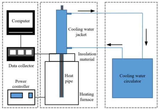
Figure 1.
Experimental system of Na-K heat pipe under forced convection cooling.
Figure 2 shows the experimental procedures. During the experiment, the heat pipe was heated from room temperature. The heating condition is that the heating power was constant at 800 W, 1000 W, 1200 W and 1400 W respectively. The cooling condition is that the cooling water flow was constant at 16 mL/s, and the temperature of constant temperature water tank was constant at 20 °C. Each temperature was obtained through the data collector, and the acquisition frequency was 3 s/time. In geyser boiling, the wall temperature of the heat pipe changes periodically and drastically. The start-up process of heat pipe is from the beginning of heating to the first boiling. From the beginning of heating to the first boiling, it is the start-up process of the heat pipe. At least 20 stable and complete boiling fluctuation cycles need to be recorded in each group of experiment. Because the heat pipe always kept geyser boiling, the time-average values of the wall temperature, the temperature of the cooling water jacket, the outlet and inlet temperature of the cooling water in the calculation are taken within 5 boiling after the stable fluctuation.
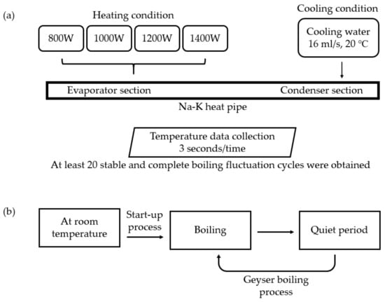
Figure 2.
Experimental procedures of Na-K heat pipe of (a) Experimental conditions; (b) Operation status of Na-K heat pipe.
The temperature of the outer wall of heat pipe, the outlet and inlet of the cooling water, the ambient and the outer wall of the cooling water jacket were measured. Figure 3 shows the distribution of temperature measuring points on the outer wall, these measuring points were numbered as P1 to P15 in turn. The evaporator section was 580 mm long with 5 measuring points, the insulation section was 90 mm long with 1 measuring point, the condenser section was 330 mm long with 9 measuring points due to the large axial temperature variation of the condenser section. The heat pipe was always placed vertically during the experiment.

Figure 3.
Location of temperature measuring points.
A Na-K alloy gravity heat pipe was used in the experiment. The mass fraction of metal potassium and sodium in the Na-K alloy are 77.8% and 22.2% respectively. Compared with sodium and potassium, the Na-K alloy has low melting point and it is liquid at room temperature. As an alkali metal heat pipe working fluid, Na-K alloy is easy to fill and will not condense in the condenser section. Table 1 presents the thermophysical properties of the Na-K alloy.

Table 1.
Thermophysical properties of the Na-K (77.8% by mass of potassium) alloy.
The shape of heat pipe is cylindrical, the parameters of the Na-K alloy heat pipe is presented in Table 2. In our previous work [24], the Na-K heat pipe had best start-up performance under the length of evaporator, condenser, and adiabatic section in Table 2.
Table 2.
Parameters of the Na-K alloy heat pipe.
The heating system is composed of single-phase full digital thyristor power controller, voltage regulating power supply and heating furnace, which can realize the constant temperature heating and the constant power heating of Na-K alloy heat pipe.
The power controller precisely controls the heating power by adjusting the voltage and current of the circuit through the thyristor controller. In this experiment, the constant power output mode was mainly used. The depth of heating furnace is 1000 mm, the resistance heating wire was used, and the heating temperature range is 20~1000 °C. The maximum temperature difference is less than 20 °C when heating at 800 °C constant temperature. The heating furnace can be heated at 0~7 kW constant power by the power controller and the control accuracy is ±0.01 kW.
The cooling system is composed of annulus type cooling water jacket and cooling water circulator. The cooling water jacket is made by stainless steel, the length of water jacket is 330 mm, which is the same as the length of condenser section. The cooling water in the jacket was upward flow and the gap between the cooling water jacket and the condensation section of the heat pipe was filled with copper powder. The temperature control accuracy of the cooling water circulator is ±0.1 °C and the flow control accuracy is ±0.3 mL/s.
The temperature data were recorded by a data collector with voltage accuracy of 0.004%.
Because the gap between cooling water jacket and heat pipe is very small and the volume of standard thermocouple is too large to be arranged on the condenser section wall. Therefore, the self-made K-type thermocouples which were welded with 0.2 mm diameter nickel-chromium alloy wires and nickel-aluminum alloy wires were used after calibrated by China Institute of Metrology, and the uncertainty of all self-made K-type thermocouples is 1.2 K.
3.2. Data Processing
The calculation methods of the equivalent heat transfer coefficient, the equivalent thermal resistance, and the heat transfer coefficient of evaporator section and condenser section are shown in Equations (1)–(5). The equations were taken from the National standards of China “Testing method for heat transfer performance of heat pipes (GB/T14812-2008)”. The heat transfer quantity can be calculated by subtracting the heat leakage of cooling water jacket from the cooling water.
The hja is the convective heat transfer coefficient between water jacket out wall and air, it is about 20 W/(m2·°C). The equivalent heat transfer coefficient can be calculated by considering the heat pipe as a uniform solid,
The heat leakage of heat pipe insulation section and the heat resistance of heat pipe wall is small, so the insulation section temperature can be used as the temperature of working fluid vapor of heat pipe. The heat transfer coefficient of evaporator section and condenser section can be defined as
The equivalent thermal resistance can be defined as
In Equations (2)–(5), the average wall temperature was taken as the average temperature of each section.
According to the measurement accuracy of temperature and heating power, the uncertainty of thermal resistance and effective thermal conductivity was calculated. The uncertainty of thermal resistance is defined as [36]
Therefor, the maximum relative thermal resistance uncertainty was ±0.41%.
3.3. Experimental Repeatability
Figure 4 shows the reproducibility of the time-average wall temperature. Three experiments under the same conditions were completed in three different days. The heating power was 800 W, the cooling water temperature was 20 °C and the cooling water flow rate was 16 mL/s. From this Figure, the experimental error of time-average wall temperature of heat pipe was less than 2%. Therefore, it could be considered that the experimental results were accurate.
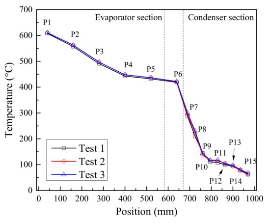
Figure 4.
Reproducibility of time-average wall temperature of Na-K alloy heat pipe.
4. Results and Discussions
4.1. Start-Up Process
During the start-up process of Na-K alloy heat pipe, the flow state of working fluid will transform from the rarefied vapor flow to the continuum vapor flow. The Na-K alloy heat pipe can only achieve efficient heat transfer when the continuum vapor flow is established. Knudsen number can be used to determine whether the working fluid forms continuous flow, the Knudsen number can be calculated by the ratio of mean free path of working fluid and diameter of the vapor flow passage.
It is generally believed that continuous flow can be formed only when Knudsen number is less than 0.01 [20,37]. The temperature that can make the working fluid vapor form a continuous flow is named the transition temperature, it can be defined as [20,37]
The vapor transition temperature is mainly affected by the height of vapor space which is the inner diameter of heat pipe. The transition temperature of Na-K (77.8% by mass of potassium) alloy is about 340.2 °C when the inner diameter of the heat pipe is 20 mm.
Figure 5 shows the temperature variation of each measurement point under different heating power during the start-up process and working process. The sonic limit appeared in the start-up process under all heating power. The sonic limit is very common in the start-up process of alkali metal heat pipes, and it will disappear with the increase of vapor temperature [38]. An intense boiling occurred in the heat pipe after heating for 25 to 40 min under all heating power, the evaporator section temperature decreased sharply while the condenser section temperature increased rapidly. Because a large amount of high temperature vapor flowed to the condenser section, and the sound of liquid working fluid impacting the end cover of condenser section could be heard clearly during the boiling.
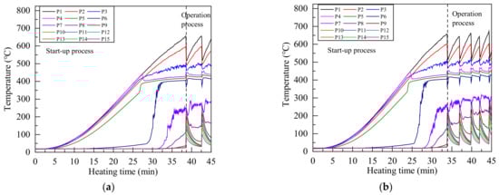
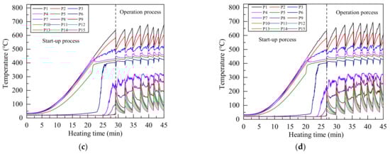
Figure 5.
Temperature distribution of Na-K alloy heat pipe under heating power of (a) 800 W; (b) 1000 W; (c) 1200 W; (d) 1400 W.
Due to the intense boiling and strong forced convection cooling, the evaporator section temperature decreased greatly after the first boiling, and a large amount of heat was taken away by the cooling water, so the heat pipe can not maintain continuous boiling state. Therefore, the condenser section temperature began to decrease, and the evaporator section temperature raised. About 2 to 3 min later, another intense boiling occurred and this process was repeated, then the geyser boiling occurred in the heat pipe [28,38]. Because the melting point of Na-K alloy is lower than room temperature and there is no solidification limit, the working fluid will not solidify into solid state in the condenser section. Even if the condenser section temperature was reduced to 40 °C during the geyser boiling process, the Na-K alloy heat pipe can work normally.
Since measuring point 1 to measuring point 5 were in the evaporator section, the temperature rises gently in the start-up stage. When the heating time was 20 min to 25 min, the temperature of measuring point 4 decreases slightly, because the liquid level of liquid Na-K alloy is lower than measuring point 4. At this time, the Na-K alloy had begun a large number of phase transformation on the liquid surface, and the temperature change of measuring point 4 in the start-up stage was very small.
The flow state of Na-K alloy transformed from the rarefied vapor flow to the continuum vapor flow when temperature reached the transition temperature, and the flow of Na-K alloy increased greatly, which greatly increased the wall temperature of heat pipe. The temperature of measuring point 6 in the adiabatic section rose sharply at 20 min to 30 min, indicating that the working fluid in the adiabatic section had changed to continuous vapor flow at this time. Since the liquid level of Na-K alloy is lower than measuring point 4, measuring point 5 in the evaporation section also had the process of flow state transformation, and the temperature of measuring point 5 also increased greatly in a short time. The temperature from measuring point 4 to measuring point 6 was maintained at about 400 °C after flow state transformation, which is close to the theoretical transition temperature of Na-K alloy.
In the start-up state, because there were few Na-K alloys entering the condenser section, the temperature of only a few measuring points increased, and most measuring points were at room temperature. Therefore, geyser boiling can occur before continuous flow is formed in the condenser section under forced convection cooling.
4.2. Working Process
In the working state, when the temperature of measuring point 1 at the bottom of the heat pipe reached about 650 °C, a violent boiling occurred at the bottom of the heat pipe to produce Taylor bubble, which is a kind of elastic flow bubble. A large amount of vapor carried liquid Na-K alloy into the condenser section, reduced the temperature of each measuring point in the evaporator section and increased the temperature of each measuring point in the condenser section, and the sound of liquid working fluid hitting the top of the heat pipe could be heard. Then, due to the strong cooling capacity of the cooling water, the heat input in the evaporation section was not enough to maintain the continuous boiling of Na-K alloy, so that the temperature of each measuring point in the condenser section decreased rapidly, and the temperature of each measuring point in the evaporator section rose again. A new boiling occurred when the temperature of measuring point 1 reached about 650 °C again, and then the heat pipe repeated this process to form geyser boiling.
Compared with the temperature fluctuation under different heating power in Figure 5, with the increased of heating power, the temperature distribution at the beginning and the end of each single boiling was very close. Because the working fluid returned to the same state after each boiling, increasing the heating power only increases the boiling frequency.
The time-average wall temperature of each measurement point is the average value of temperature within 5 boiling after the stable fluctuation. Figure 6 shows the time-average wall temperature distribution of heat pipe under different heating power. The average temperature of condenser section was obviously increased with the heating power, and the temperature uniformity was slightly improved. Due to the strong heat transfer ability of forced convection, there was a large temperature gradient along the heat pipe, the vapor temperature decreased rapidly after entered the condenser section. The temperature gradient at 795 mm to 970 mm decreased obviously, indicating that there was less Na-K alloy here and the flow state is rarefied vapor flow.

Figure 6.
Average temperature distribution of heat pipe under different heating power.
Figure 7 shows the start-up time and average temperature of evaporator section during each boiling under different heating power. The start-up time is the first time of intense boiling of the heat pipe. The average temperature of evaporator section was calculated according to Equation (6) from Figure 6. The start-up time decreased as the heating power increases, indicating that the heating power has greater influence on the temperature of working fluid in the non-boiling state. The next boiling time will be reduced, and it can be seen in Figure 5 that the fluctuation frequency increased at higher heating power. Geyser boiling would not make the maximum temperature of evaporator section continue to increase, the temperature of P6 in the insulation section was maintained at about 400 °C. That meant the starting condition of each boiling and the temperature of vapor was very close to 400 °C during a single boiling, so the average temperature of evaporator section had small differences, and the temperature of the evaporation section is relatively close in Figure 6. It means that Na-K alloy heat pipes can work at lower temperature under geyser boiling. With the increased of heating power, the mass of vapor produced in single boiling increased, and the average temperature of evaporation section increased after a single boiling.
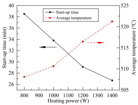
Figure 7.
Start-up time and average temperature of evaporator section during the each boiling under different heating power.
Figure 8 shows the average temperature difference of some measurement point at the condenser section in each single boiling and the average fluctuation cycle of each single boiling. With the increased of heating power, the evaporation of the working fluid increased, and the condenser section temperature increased obviously after the end of single boiling. Since the average temperature of evaporation section under different heating power in Figure 7 has little difference, it shows that the mass flow of working fluid during single boiling increases with the heating power. When the heating power was 800 W, the geyser boiling cycle was obviously longer, so the temperature difference in the condenser section was obvious in Figure 6. The lower heating power made the temperature rise slowly in the evaporator section, it took a longer time to reach the required boiling temperature. As the heating power reached 1400 W, the mass of vapor reaching the condenser section was higher, and it needed more time to cool due to the heat dissipation condition of the condenser section, so the temperature fluctuation frequency was close to the frequency under 1200 W heating.
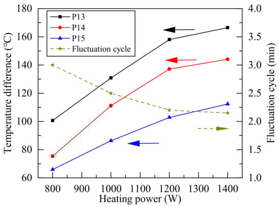
Figure 8.
Average temperature difference and fluctuation cycle of condenser section during geyser boiling.
4.3. Heat Transfer Performance
The temperature change in the middle of the condenser section was most obvious in a single boiling. The wall temperature was greatly affected by the cooling water when the vapor just entered the condenser section. Because the vapor temperature was higher before boiling, the wall temperature change was small at the entrance of condenser section. When the vapor arrived the end of the condenser section, most of the heat had been taken away by the cooling water, the cooling water temperature was also increased and the cooling capacity decreased, so the temperature change of the heat pipe was also small at end of the condenser section.
Figure 9 and Figure 10 show the heat transfer quantity, the equivalent heat transfer coefficient, the equivalent thermal resistance, and the surface heat transfer coefficient of evaporator section and condenser section of heat pipe during working process according to Equations (1)–(5). With the increase of heating power, the heat transfer performance of heat pipe was improved. Because the average temperature of the evaporator section changed little, it can be further proved that the mass flow of working fluid increases with the heating power in single boiling. The heat transferred by the heat pipe was only about half of the input of the heating controller, and a lot of heat was lost by the heating furnace. In this study, the minimum thermal resistance was about 0.6 K/W, and equivalent heat transfer coefficient could reach about 5500 W/(m2·°C).

Figure 9.
Heat transfer quantity and equivalent thermal resistance of heat pipe under different heating power.
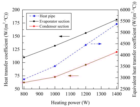
Figure 10.
Heat transfer coefficient of heat pipe under different heating power.
Compared with Figure 6, Figure 9 and Figure 10, although there was a large temperature gradient along the heat pipe under 800 W to 1400 W heating, the increased of heating power could improve the evaporation rate and promoted the heat transfer of the evaporator section. Due to a large amount of vapor entered the condenser section, the heat transfer of the condenser section had been promoted and the vapor flow rate was increased, so the heat transfer coefficients increased linearly.
Table 3 presents the operating parameters of Na-K heat pipe under different heating power. From the Table 3, the effective heat transfer of heat pipe increased with the heating power, but the maximum temperature of heat pipe and the average temperature of evaporation section (Te) change little, while the fluctuation cycle of geyser boiling decreased and the average temperature of condensation section (Tc) increased. Therefor, the geyser boiling mainly increases heat transfer by increasing boiling frequency rather than increasing the temperature of Na-K heat pipe.
Table 3.
Operating parameters of Na-K heat pipe under different heating power.
Although geyser boiling will cause temperature fluctuation and shell vibration. Geyser boiling can make Na-K alloy heat pipe working at lower temperature. Table 3 presents the maximum temperature of heat pipe under geyser boiling was only about 700 °C when the effective heat transfer quantity of heat pipe reached 800 W. Compared with our previous work of Guo et al. [24], under the natural convection cooling, the effective heat transfer quantity can reach 800 W only when the maximum temperature is above 800 °C. Therefore, geyser boiling reduced the operating temperature of the Na-K alloy heat pipe by 100 °C.
Geyser boiling also can make Na-K alloy heat pipe have higher heat transfer quantity at lower temperature. Figure 6 and Table 3 present that when the maximum average temperature of the evaporator section was 600 °C, the effective heat transfer quantity under geyser boiling reached 800 W. While the Na-K alloy heat pipe has not start at the same temperature under natural convection cooling conditions, and the effective heat transfer was less than 50 W [24,25].
5. Conclusions
Due to geyser boiling can occur before continuous flow is formed in the condenser section under forced convection cooling, the start-up capacity and heat transfer capacity of a Na-K alloy heat pipe under forced convection cooling were experimentally studied at different heating power (800 W, 1000 W, 1200 W and 1400 W). The Na-K alloy heat pipe can work in geyser boiling mode, and transfer a lot of heat quantity at lower temperature than natural convection cooling. The main conclusions were as follows:
- (1)
- Geyser boiling can reduce the minimum operating temperature of Na-K alloy heat pipe, and can have higher heat transfer capacity than natural convection cooling at lower temperature.
- (2)
- In the geyser boiling process, the increase in the average temperature of the condensing section is caused by the increase in the mass flow of the Na-K alloy working fluid. And the small change in the average temperature of the evaporation section is caused by the small change in the boiling temperature.
- (3)
- The increase of heating power leads to the increase of Na-K alloy working fluid mass flow during single boiling, which further leads to a linear increase of heat transfer capacity. But because of the cooling capacity, the boiling frequency does not increase linearly.
Author Contributions
Conceptualization, H.Z. and H.G.; Data curation, H.Z.; Formal analysis, H.Z.; Funding acquisition, F.Y. and X.Y.; Investigation, H.Z.; Methodology, H.Z.; Project administration, F.Y. and X.Y.; Resources, F.Y. and X.Y.; Supervision, H.G. and F.Y.; Visualization, H.Z.; Writing-original draft, H.Z.; Writing-review and editing, H.G. and F.Y. All authors listed have made a substantial, direct, and intellectual contribution to the work. All authors have read and agreed to the published version of the manuscript.
Funding
This work was funded by the National Key R&D Program of China [grant number 2017YFF0205901].
Data Availability Statement
The supporting data will be made available on request.
Conflicts of Interest
The authors declare that they have no conflict of interest.
Nomenclature
| A | Surface area, m2 |
| Ahp | Heat pipe axial section area, m2 |
| cp | Specific heat of cooling water, J/(kg·K) |
| D | Height of vapor space, m |
| G | Mass flow of cooling water, kg/s |
| h | Heat transfer coefficient, W/(m2·K) |
| hja | Convective heat transfer coefficient between outer wall of cooling water jacket and air, W/(m2·K) |
| K | Equivalent heat transfer coefficient of the heat pipe, W/(m2·K) |
| M | Molar mass, g/mol; |
| P | Measuring point |
| Q | Heat transfer quantity of heat pipe, W |
| R | Thermal resistance, °C/W |
| Rg | Universal gas constant, J/(K·mol) |
| T | Time-averaged temperature, °C |
| Ttr | Vapor transition temperature, K |
| Greek symbols | |
| ρ | Density, kg/m3 |
| μ | Viscosity, Pa·s |
| λ | Length of mean free path of vapor, m |
| Subscripts | |
| 1–15 | Measuring point 1 to 15 |
| a | Adiabatic section |
| c | Condenser section |
| e | Evaporation section |
| j | Water jacket |
| v | Vapor |
References
- Panda, K.K.; Dulera, I.V.; Basak, A. Numerical simulation of high temperature sodium heat pipe for passive heat removal in nuclear reactors. Nucl. Eng. Des. 2017, 323, 376–385. [Google Scholar] [CrossRef]
- Kusuma, M.H.; Putra, N.; Antariksawan, A.R.; Koestoer, R.A.; Widodo, S.; Ismarwanti, S.; Verlambang, B.T. Passive cooling system in a nuclear spent fuel pool using a vertical straight wickless-heat pipe. Int. J. Therm. Sci. 2018, 126, 162–171. [Google Scholar] [CrossRef]
- Yan, X.K.; Duan, Y.N.; Ma, C.F.; Lv, Z.F. Construction of sodium heat-pipe furnaces and the isothermal characteristics of the furnaces. Int. J. Thermophys. 2011, 32, 494–504. [Google Scholar] [CrossRef]
- Astrua, A.M.; Iacomini, L.; Battuello, M. The combined use of a gas-controlled heat pipe and a copper point to improve the calibration of thermocouples up to 1100 °C. Int. J. Thermophys. 2008, 32, 1838–1847. [Google Scholar] [CrossRef]
- Bertiglia, F.; Iacomini, L.; Moro, F.; Merlone, A. Comparison of two potassium-filled gas-controlled heat pipes. Int. J. Thermophys. 2015, 32, 3393–3403. [Google Scholar] [CrossRef]
- Mahboobe, M.; Qiu, S.G.; Saeed, T. Numerical investigation of hydrodynamics and thermal performance of a specially configured heat pipe for high-temperature thermal energy storage systems. Appl. Therm. Eng. 2015, 81, 325–337. [Google Scholar]
- Liao, Z.; Faghri, A. Thermal analysis of a heat pipe solar central receiver for concentrated solar power tower. Appl. Therm. Eng. 2016, 102, 952–960. [Google Scholar] [CrossRef]
- Yuan, Y.; Shan, J.Q.; Zhang, B.; Gou, J.L.; Zhang, B.; Lu, T.Y.; Ge, L.; Yang, Z.J. Study on startup characteristics of heat pipe cooled and AMTEC conversion space reactor system. Prog. Nucl. Energy 2016, 86, 18–30. [Google Scholar] [CrossRef]
- Wang, C.L.; Liu, L.; Liu, M.H.; Zhang, D.L.; Tian, W.X.; Qiu, S.Z.; Su, G.H. Conceptual design and analysis of heat pipe cooled silo cooling system for the transportable fluoride-salt-cooled high-temperature reactor. Ann. Nucl. Energy 2017, 109, 458–468. [Google Scholar] [CrossRef]
- Liu, M.H.; Zhang, D.L.; Wang, C.L.; Qiu, S.Z.; Su, G.H.; Tian, W.X. Experimental study on heat transfer performance between fluoride salt and heat pipes in the new conceptual passive residual heat removal system of molten salt reactor. Nucl. Eng. Des. 2018, 339, 215–224. [Google Scholar] [CrossRef]
- Behi, H.; Kalogiannis, T.; Patil, M.S.; Mierlo, J.V.; Berecibar, M. A new concept of air cooling and heat pipe for electric vehicles in fast discharging. Energies 2021, 14, 6477. [Google Scholar] [CrossRef]
- Xiao, H.; George, F. Design and fabrication of hybrid bi-modal wick structure for heat pipe application. J. Porous Mat. 2008, 15, 635–642. [Google Scholar]
- Behi, H.; Behi, M.; Ghanbarpour, A.; Karimi, D.; Azad, A.; Ghanbarpour, M.; Behnia, M. Enhancement of the thermal energy storage using heat-pipe-assisted phase change material. Energies 2021, 14, 6176. [Google Scholar] [CrossRef]
- Chen, J.; Dong, J.B.; Yao, Y. Experimental study on the starting-up and heat transfer characteristics of a pulsating heat pipe under local low-frequency vibrations. Energies 2021, 14, 6310. [Google Scholar] [CrossRef]
- Anderson, W.G. Sodium-Potassium (NaK) Heat Pipe. In Proceedings of the 29th National Heat Transfer Conference, Atlanta, GA, USA, 8–11 August 1993; Volume 236, pp. 47–53. [Google Scholar]
- Serizawa, A.; Ida, T.; Takahashi, O.; Michiyoshi, I. MHD effect on NaK-nitrogen two-phase flow and heat transfer in a vertical round tube. Int. J. Multiph. Flow 1990, 16, 761–788. [Google Scholar] [CrossRef]
- Schriener, T.M.; El-Genk, M.S. Convection heat transfer of NaK-78 liquid metal in a circular tube and a tri-lobe channel. Int. J. Heat Mass Transf. 2015, 86, 234–243. [Google Scholar] [CrossRef]
- Ji, Y.L.; Wu, M.K.; Feng, Y.M.; Yu, C.R.; Chu, L.L.; Chang, C.; Li, Y.T.; Xiao, X.; Ma, H.B. An experimental investigation on the heat transfer performance of a liquid metal high-temperature oscillating heat pipe. Int. J. Heat Mass Transf. 2020, 149, 119198. [Google Scholar] [CrossRef]
- Wang, C.L.; Guo, Z.P.; Zhang, D.L.; Qiu, S.Z.; Tian, W.X.; Wu, Y.W.; Su, G.H. Transient behavior of the sodium-potassium alloy heat pipe in passive residual heat removal system of molten salt reactor. Prog. Nucl. Energy 2013, 68, 142–152. [Google Scholar] [CrossRef]
- Li, T.; Jiang, Y.Y.; Li, Z.G.; Liu, Q.; Tang, D.W. Loop thermosiphon as a feasible cooling method for the stators of gas turbine. Appl. Therm. Eng. 2016, 109, 449–453. [Google Scholar] [CrossRef]
- Jia, X.J.; Guo, H.; Guo, Q.; Yan, X.K.; Ye, F.; Ma, C.F. Effect of heating temperature on start-up and heat transfer performance of Na-K alloy heat pipe. Acta Energ. Sol. Sin. 2019, 40, 17–23. (In Chinese) [Google Scholar]
- Zhang, H.Z.; Jia, X.J.; Guo, H.; Guo, Q.; Yan, X.K.; Ye, F.; Ma, C.F. Effect of cooling water parameters on heat transfer performance of sodium-potassium alloy heat pipe. J. Chem. Ind. Eng. 2017, S1, 105–110. (In Chinese) [Google Scholar]
- Guo, H.; Guo, Q.; Yan, X.K.; Ye, F.; Ma, C.F. Experimental investigation on heat transfer performance of high-temperature thermosyphon charged with sodium-potassium alloy. Appl. Therm. Eng. 2018, 139, 402–408. [Google Scholar] [CrossRef]
- Guo, Q.; Guo, H.; Yan, X.K.; Ye, F.; Ma, C.F. Influence of inclination angle on the start-up performance of a sodium-potassium alloy heat pipe. Heat Transf. Eng. 2017, 4, 1–9. [Google Scholar] [CrossRef]
- Noie, S.H.; Sarmastiemami, M.R.; Khoshnoodi, M. Effect of inclination angle and filling ratio on thermal performance of a two-phase closed thermosyphon under normal operating conditions. Heat Transfer. Eng. 2007, 28, 365–371. [Google Scholar] [CrossRef]
- Emani, M.R.S.; Noie, S.H.; Khoshnoodi, M.; Mosavian, M.T.H.; Kianifar, A. Investigation of geyser boiling phenomenon in a two-phase closed thermosyphon. Heat Transfer Eng. 2009, 30, 408–415. [Google Scholar] [CrossRef]
- Lin, T.F.; Lin, W.T.; Tsay, Y.L.; Wu, J.C. Experimental investigation of geyser boiling in an annular two phase closed thermosyphon. Int. J. Heat Mass Transfer 1995, 38, 295–307. [Google Scholar] [CrossRef]
- Wang, X.; Wang, Y.; Chen, H.; Zhu, Y.A. Combined CFD/visualization investigation of heat transfer behaviors during geyser boiling in two-phase closed thermosyphon. Int. J. Heat Mass Transfer 2018, 121, 703–714. [Google Scholar] [CrossRef]
- Casarosa, C.; Latrofa, E.; Shelginski, A. The geyser effect in a two phase thermosyphon. Int. J. Heat Mass Transfer 1983, 6, 933–941. [Google Scholar] [CrossRef]
- Kujawska, A.; Zajaczkowski, B.; Wilde, L.M.; Buschmann, M.H. Geyser boiling in a thermosyphon with nanofluids and surfactant solution. Int. J. Therm. Sci. 2019, 139, 195–216. [Google Scholar] [CrossRef]
- Morgan, S.K.; Brady, H.F. Elimination of the geyser effect in missiles. Adv. Cryog. Eng. 1962, 7, 206–213. [Google Scholar]
- Howard, F.S. Geysering inhibitor for vertical cryogenic transfer piping. Adv. Cryog. Eng. 1973, 18, 162–169. [Google Scholar]
- Kuncoro, H.; Rao, Y.F.; Fukuda, K. An experimental study on the mechanism of geysering in a closed two-phase thermosyphon. Int. J. Multiph. Flow 1995, 21, 1243–1252. [Google Scholar] [CrossRef]
- Tecchio, C.; Oliveira, J.L.G.; Paiva, K.V.; Mantelli, M.B.H.; Galdolfi, R.; Ribeiro, L.G.S. Geyser boiling phenomenon in two-phase closed loop-thermosyphons. Int. J. Heat Mass Transfer 2017, 111, 29–40. [Google Scholar] [CrossRef]
- Bao, K.L.; Wang, X.H.; Fang, Y.B.; Jia, X.S.; Han, X.H.; Chen, G.M. Effects of the surfactant solution on the performance of the pulsating heat pipe. Appl. Therm. Eng. 2020, 178, 115678. [Google Scholar] [CrossRef]
- Jang, J.H. Startup characteristics of a potassium heat pipe from the frozen state. J. Thermophys. Heat Transf. 1995, 9, 117–122. [Google Scholar] [CrossRef]
- Wang, C.L.; Liu, X.; Liu, M.H.; Tang, S.M.; Tian, Z.X.; Zhang, D.L.; Tian, W.X.; Qiu, S.Z.; Su, G.H. Experimental study on heat transfer limit of high temperature potassium heat pipe for advanced reactors. Ann. Nucl. Energy 2021, 151, 107935. [Google Scholar] [CrossRef]
- Mahan, J.R.; Felske, J.D. Radiation heat transfer: A statistical approach. Appl. Mech. Rev. 2002, 56, B15–B16. [Google Scholar] [CrossRef]
Publisher’s Note: MDPI stays neutral with regard to jurisdictional claims in published maps and institutional affiliations. |
© 2021 by the authors. Licensee MDPI, Basel, Switzerland. This article is an open access article distributed under the terms and conditions of the Creative Commons Attribution (CC BY) license (https://creativecommons.org/licenses/by/4.0/).