Article

Experimental Study on Pool Boiling on Hydrophilic Micro/Nanotextured Surfaces with Hydrophobic Patterns

1
Department of Mechanical Design Engineering, Pukyong National University, Busan 48513, Korea
2
Department of Nuclear Engineering, Hanyang University, Seoul 04763, Korea
*
Author to whom correspondence should be addressed.
Energies 2021, 14(22), 7543; https://doi.org/10.3390/en14227543
Submission received: 27 October 2021 / Revised: 4 November 2021 / Accepted: 9 November 2021 / Published: 11 November 2021
(This article belongs to the Special Issue Two-Phase Flow with Boiling Heat Transfer)

Abstract

:
Over the past decades, pool boiling on various wetting surfaces has been intensively investigated to enhance boiling heat transfer and critical heat flux. In this study, to enhance the two thermal performances simultaneously, we developed hydrophilic micro/nanotextured surfaces with hydrophobic patterns. Using a silicon substrate, well-arrayed microtextures and randomly arrayed nanotextures were fabricated hierarchically using micro/nanoelectromechanical system processes. The top of the microtextures was coated locally with hydrophobic characteristics using specific self-assembled monolayer coating methods. Based on experimental data, we postulate that the critical heat flux was enhanced by the capillary-induced flow between microtextures and that nanotextures with superhydrophilicity contribute to the delay of the critical heat flux by better wetting the dried area. Owing to the hydrophobicity at the top of the micropillars, the nucleate site density and boiling heat transfer increased.

Graphical Abstract

1. Introduction

Boiling heat transfer is a heat transfer mechanism with a better performance than that of natural and forced convection. It is used in industrial fields including thermal power generation, nuclear reactors, and high-power electronic devices [1,2,3]. Boiling heat transfer is evaluated mainly by two factors: critical heat flux (CHF) and heat transfer coefficient (HTC). The CHF represents the limit of the nucleate boiling regime. When the heat flux exceeds the CHF, the surface is covered with a vapor film and the surface temperature increases rapidly in the film boiling region because of the low thermal conductivity of the vapor. A high surface temperature can exceed the material property limits and lead to system failure. Therefore, a high CHF implies that it is possible to stably remove a large amount of heat by expanding the nucleate boiling regime. The HTC represents the heat-dissipation efficiency. A high HTC implies that a large amount of heat can be removed at low surface temperatures, thereby improving the system efficiency. Recently, numerous studies have demonstrated enhancements in CHF and HTC to stably and efficiently remove heat from the system.
Studies have been carried out to enhance the CHF through surface modification at the microscale [4,5,6,7], nanoscale [8,9,10,11], and mixed micro/nanoscale [12,13,14]. Chu et al. [4] reported an enhancement in the CHF on the surface of a micropillar array. They derived a model in which the CHF increased according to the surface roughness by considering the increase in the contact line length in the Kandlikar’s model. Kim et al. [5] suggested that the CHF triggering mechanism on microstructured surfaces is affected by the departure frequency of the coalesced bubble and ability to furnish liquid to the surface. Kim et al. [6] reported the enhancement effect of CHF and HTC according to the roughness considering the diameter, spacing, and height of the micropillars. They reported that capillary-induced liquid flow attributed to the micropillars enhanced the CHF. Yu et al. [7] visualized the behavior of liquid–vapor interfaces underneath the nucleate bubbles on micropillar surfaces with varying roughness by synchrotron X-ray imaging. They demonstrated that the liquid–vapor interfaces between the micropillars were more concave at the center of the nucleate bubble than at the sides of the nucleate bubble and reported that the liquid was supplied between the micropillars by a local difference in the capillary pressure.
Chen et al. [8] obtained enhancements in the CHF and HTC of 100% on both silicon and copper nanowire surfaces. They reported that the HTC increased with the nucleate site density and that the CHF was enhanced by superhydrophilicity and capillary pumping effect. Shim et al. [9] reported that the aligned silicon nanowire surface had a higher CHF because aligned silicon nanowires exhibited higher volumetric wicking rates than those of random silicon nanowires. Nguyen et al. [10] reported that the CHF was enhanced because the capillary force was enhanced by the presence of nanopillars. They estimated the rewetting velocity as the spreading velocity by dropping liquid on the nanopillar surface at various surface temperatures without boiling.
Ahn et al. [11] evaluated the behaviors of capillary wicking on micro-, nano-, and micro/nanostructure surfaces by measuring the volume of absorbed water. They improved the Kandlikar’s correlation by considering the effect of water absorption due to capillary wicking. They obtained the highest water absorption rate on the micro/nanostructured surface and reported the highest CHF enhancement on a micro/nanostructured surface. Rahman et al. [12] also measured the wickability of the surface through the volume of water absorbed from a hierarchical surface with micro- and nanostructures. They reported that the CHF was enhanced up to 2570 kW/m2 for water on virus-structured hierarchical surfaces. Dhillon et al. [13] carried out pool boiling with microtextured and micro/nanotextured surfaces with different micropillar spacings. They reported that the CHF increased as the spacing of the micropillars decreased but decreased after the limit spacing (~10 µm). Thus, according to the previous studies, the wetted surface can be maintained by the capillary phenomenon attributed to the structure at a high heat flux.
The CHF and HTC exhibit different patterns depending on the wettability of the surface [14,15,16,17,18]. Kandlikar [14] derived a CHF model based on the force balance for bubble growth on a smooth surface. His model showed a higher CHF as the receding contact angle is smaller. Phan et al. [15] investigated the effect of surface wettability on the nucleation mechanism and boiling heat transfer. On hydrophobic surfaces, bubbles are formed at a low heat flux, but the bubbles cannot detach from the surface and coalesce with surrounding bubbles. However, if the contact angle decreases on the hydrophilic surface, the bubble departure diameter increases and the bubble frequency decreases. Bourdon et al. [16,17,18] experimentally demonstrated that a smaller contact angle of the surface corresponds to a higher wall superheat at the onset of nucleate boiling (ONB). Thus, according to previous studies [14,15,16,17,18], the hydrophilic surface has a high CHF, whereas the hydrophobic surface has a low CHF. However, the wall temperature at the ONB is high on a hydrophilic surface and low on a hydrophobic surface. The low wall temperature at the ONB indicates an early nucleate boiling regime, which has a high heat transfer coefficient, thereby enhancing the HTC. However, there is a limit to the increase in nucleate site density due to the large contact diameter. The HTC enhancement rate quickly decreases. Therefore, studies on heterogeneous wetting surfaces capable of limiting the contact diameter have been recently carried out.
Betz et al. [19] reported that the CHF and HTC were enhanced by up to 65% and 100% on a biphilic surface consisting of a hydrophilic surface with a contact angle of 7° and hydrophobic surface with a contact angle of 110°, respectively. In a follow-up study, Betz et al. [20] investigated superbiphilic surfaces with superhydrophilic (contact angle of ~0°) and superhydrophobic (contact angle of 150~160°) patterns. The superbiphilic surface achieved the highest HTC, higher than 100 kW/(m2K). Jo et al. [21] carried out pool boiling with heterogeneous wetting surfaces with hydrophobic dots on a hydrophilic surface. They reported that the hydrophobic area ratio did not affect the HTC while the dot diameter, pitch, and number of dots had dominant effects on the HTC. Jo et al. [22] studied single-bubble dynamics on biphilic surfaces. They observed the pinning phenomenon, contact angle transition, “stick–slip” behavior, and interface necking of bubbles in hydrophobic conditions. Motezakker et al. [23] arranged a hydrophobic pattern on a hydrophilic surface at the same pitch. They obtained the highest CHF and HTC on the surface with a hydrophobic-to-hydrophilic area ratio of 38.46%. Jo et al. [24] fabricated a surface with hydrophobic patterns onto the heads of a micropillar to obtain synergistic effects with wetting patterns and structures. They simultaneously enhanced the CHF and HTC by separating the vapor path on the hydrophobic pattern and liquid path between the micropillars.
In this study, we fabricated the surface which was mixed with micro/nanotextured and hydrophobic patterns. As illustrated by many studies, micro and nanotextured surfaces enhance the CHF by the capillary effect and a heterogeneous wetting surface enhances the HTC without deterioration of CHF. We conducted pool boiling experiments to obtain the simultaneous enhancement of CHF and HTC. We also conducted spreading tests that showed wickability on micro/nanotextured surface. This wickability estimates the enhancement rate of CHF. Furthermore, we observed differences in bubble dynamics according to the presence or absence of the hydrophobic pattern with a high-speed camera. Therefore, this study contributes to the understanding of boiling heat transfer on surfaces where textures and heterogeneous wettability are mixed.

2. Materials and Methods

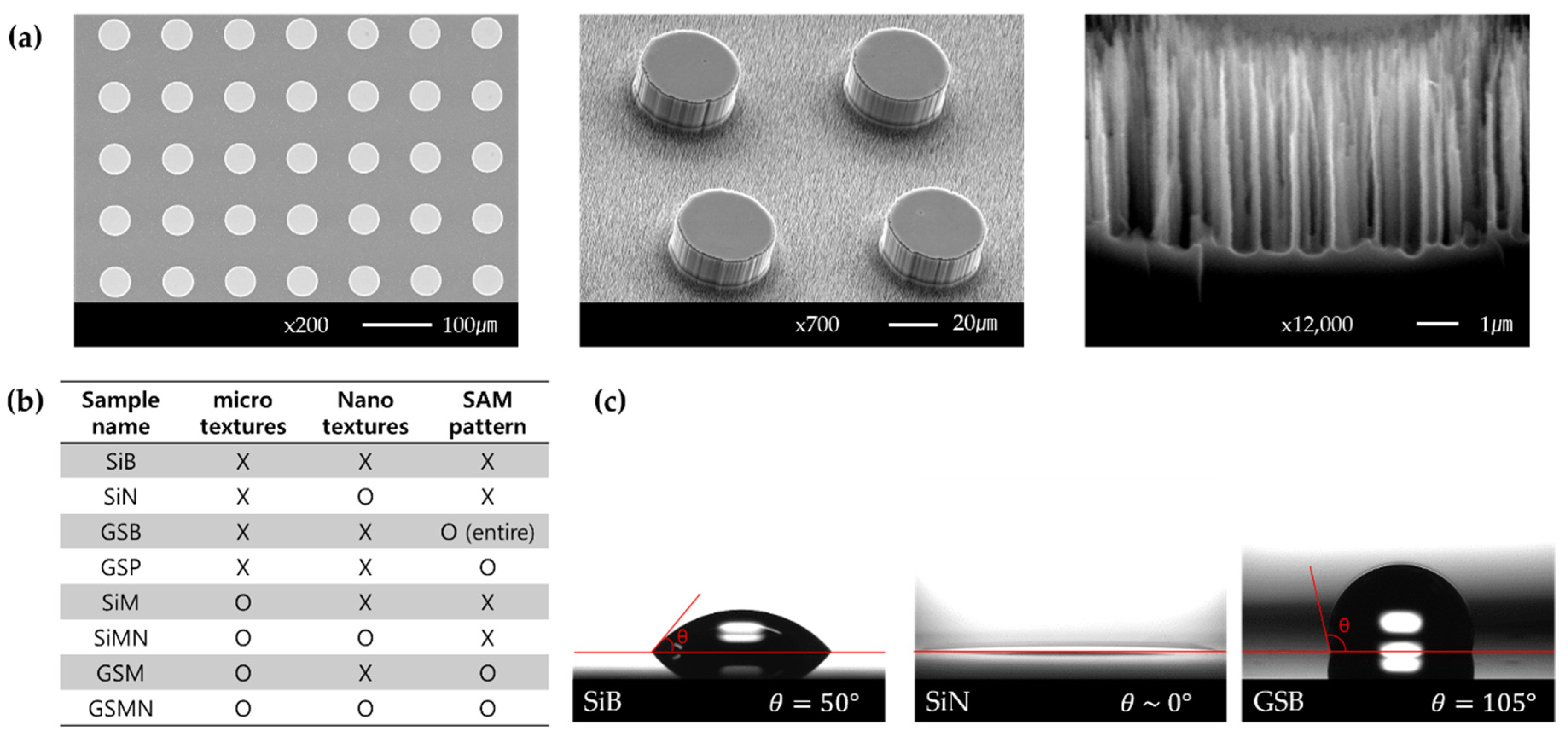
2.1. Surface Modification

The test sample in this study had a silicon substrate. The surface was developed through a microelectromechanical system (MEMS)/nanoelectromechanical system (NEMS) process. Figure 1 shows a schematic of the fabrication of a platinum thin-film heater for sample heating and micro/nanotextured surface on the opposite side of the thin-film heater and self-assembled monolayer (SAM) coating method for hydrophobicity at the top surface of the micropillars.

2.1.1. Thin-Film Heater and Micro/Nanotextures

A silicon oxide layer was deposited on a 500-µm-thick silicon wafer for electrical insulation. The film heater was fabricated on one side of the wafer by a photolithography process. A platinum thin film was deposited for heating of the desired area.
On the opposite side of the platinum thin-film heater, the photoresist was masked in circles and micropillars were fabricated by a deep reactive ion etching (DRIE) process. The diameter of the micropillars and spacing between the pillars are 45 µm, while the height is 20 µm. Random nanotextures are formed on the bottom surface. Nanotextures are randomly fabricated on the bottom surface using a black silicon recipe because it is challenging to quantitatively nanoscale-pattern them by masking the photoresist. In the case of the surface with a hydrophobic top surface of micropillars, gold is deposited on the opposite side of the thin-film heater. After circular photoresist patterning, micro/nanotextured surfaces are fabricated by the DRIE process. Figure 2a shows scanning electron microscopy (SEM) images of the surfaces fabricated by the above method. Figure 2b shows the sample names according to the texture characteristics.

2.1.2. SAM

The surface with hydrophobic patterns on the top surface of the micropillars was fabricated using a SAM selectively deposited on gold. The SAM solution was prepared in a volume ratio of toluene:1-octadecanethiol of 80:1. Before immersion in the solution, the micro- and micro/nanotextured surfaces improve the self-assembly by increasing the surface free energy through O2 plasma processing. After the O2 plasma processing, the micro-and micro/nanotextured surfaces are immersed in the SAM solution for 24 h, and then cleaned with toluene, ethanol, and water in this order. Figure 2c shows the contact angles of bare silicon (SiB), nanotextures silicon (SiN), and bare gold-SAM (GSB). The contact angle of SiB, which is the reference surface, is ~50°. SiN is superhydrophilic (contact angle of ~0°). The gold surface has a contact angle of 78° before SAM coating, which is increased to 105° after the SAM coating. Therefore, GSB is hydrophobic.
Figure 1. The method of fabrication for the test samples. First, the heater surface was fabricated and the textures were fabricated on the opposite surface of the heater.
Energies 14 07543 g001

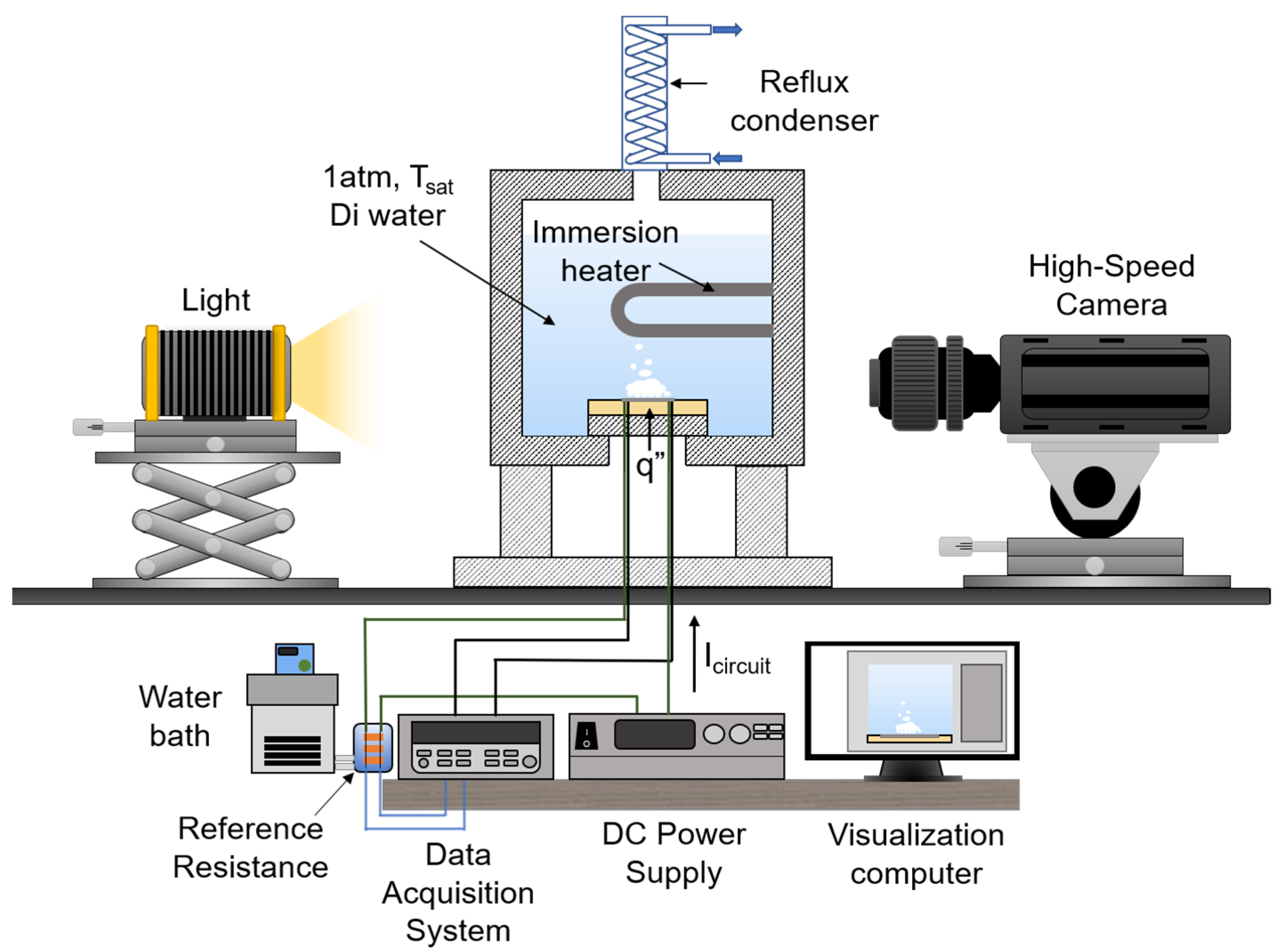
2.2. Experimental Methods

Figure 3 shows a schematic of the pool boiling experiment apparatus. The pool is composed of aluminum. The front and back of the pool are composed of polycarbonate windows to visualize the bubble dynamics. An immersion heater is installed inside the pool to maintain the working fluid in the saturated state. Deionized (DI) water is used as a working fluid in the pool boiling experiment. A reflux condenser is installed at the top of the pool to condense the vaporized working fluid and reintroduce it into the pool to maintain the water level. The jig for fixing the test sample is composed of polyether ether ketone material, which has a high thermal resistance. The test sample is fixed to the jig using an adhesive binary epoxy (Duralco 4460). In the method of heating the test sample, electric wires are connected to both ends of the platinum thin film and direct-current (DC) power is applied to the test sample; the heat is applied by the Joule heating method.
Figure 2. (a) The SEM images of micro/nanotextured surface. (b) The sample names by texture features. (c) The static contact angles of SiB, SiN, and GSB surfaces.
Energies 14 07543 g002
The pool boiling experiment is carried out under atmospheric pressure and saturation of the working fluid. To remove the residual gas dissolved in the working fluid before the experiment, the experiment is carried out after maintaining it in the saturated state for 1 h. Thereafter, the experiment is carried out by increasing the electrical power to the test sample in small steps up to the CHF. The steps increase the electrical power for 1 min. Data are acquired for 3 min to simulate a quasi-steady state at a frequency of 1 Hz. A total of 140 quasi-steady-state data points are averaged and used for sample comparison. The experiment is performed three times for all cases. The CHF is assumed to be that immediately before the rapid increase in temperature.
The data are obtained using the following equations. The heat flux is calculated by
q = V h e a t e r I c i r c u i t A h e a t e r = V h e a t e r V r e f A h e a t e r R r e f ,  
where q″, Vheater, Icircuit, Aheater, Vref, and Rref are the heat flux, voltage of the heater, current flowing through the circuit, heating area, voltage of the resistor, and resistance of the reference resistor, respectively. The heating area is 15 × 10 mm.
The wall temperature is calculated by measuring the resistance of the platinum thin-film heater according to the temperature. The first-order equation of resistance with temperature can be obtained before the experiment using the characteristic that the platinum resistance changes linearly with temperature. It is assumed that heat is transferred from the platinum surface to the surface exposed to the working fluid by one-dimensional conduction. The wall superheat is the difference between the wall temperature and adjacent liquid temperature, which is the saturation temperature in this study.
Δ T s u p e r = T w a l l T s a t = q h q t k S i T s a t ,  
where ΔTsuper, Twall, and Tsat are the wall superheat, wall temperature, and saturation temperature, respectively, t is the thickness of the substrate (500 µm), and kSi is the thermal conductivity of silicon (150 W/(mK)).
Figure 3. The pool boiling experimental apparatus.
Energies 14 07543 g003
The heat transfer coefficient is defined by the Newton’s cooling law and is calculated using
H T C = q Δ T s u p e r .  

2.3. Uncertainty Analysis

The heat flux is measured by four factors, as shown in Equation (1). Assuming that the heater area is constant, the general expression of the uncertainty is
U q 2 q 2 = U V h e a t e r 2 V h e a t e r 2 + U V r e f 2 V r e f 2 + U R r e f 2 R r e f 2 ,  
where Uq, UVheater, UVref, and URref, are the uncertainties of the heat flux, voltage of the heater, voltage of the reference resistor, and resistance of the reference resistor, respectively.
The uncertainty of the wall temperature is calculated. The general form of the relationship for the surface temperature is
Δ T s u p e r = T w a l l T s a t = a ( R h e a t e r R s a t ) = a ( V h e a t e r R r e f V r e f R s a t ) ,  
where Rheater is the resistance of the heater. Assuming that Rsat is constant, the general expression of the uncertainty is
U Δ T s u p e r 2 Δ T s u p e r 2 = U V h e a t e r 2 V h e a t e r 2 + U V r e f 2 V r e f 2 + U R r e f 2 R r e f 2 .  
Considering all instrument errors, the estimated maximum uncertainties of the heat flux and wall superheat are 3.3% and 6.4%, respectively.

3. Results and Discussion

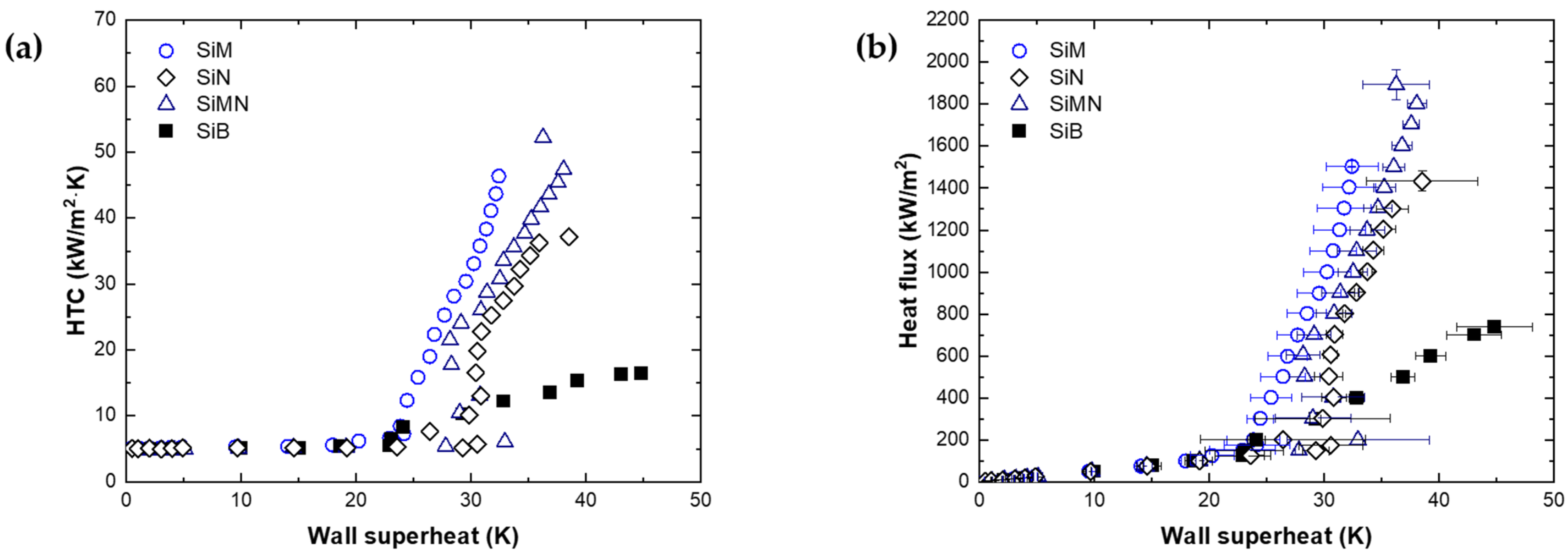
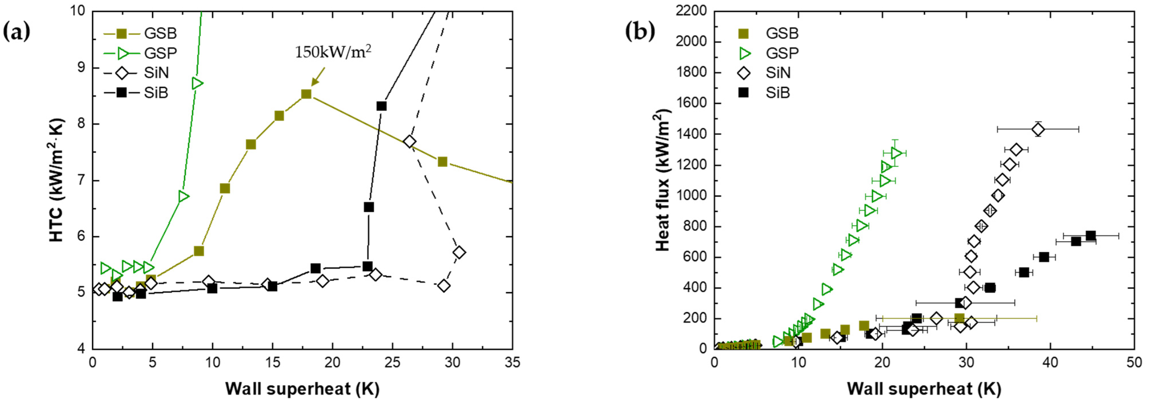
3.1. Boiling Characteristics on the Surface with Pillar Textures

We carried out a pool boiling experiment to observe the boiling phenomenon on the micro/nanotextured surface. Figure 4a shows the efficiency of boiling heat transfer. In the natural convection region before the ONB, the HTC has a similar value of approximately 5 kW/m2K without significant change according to the temperature. However, after the ONB, the HTC increases. Because the bubble nucleates and departs from the surface, the HTC increases as the liquid around the bubble is reintroduced. Figure 4b shows the heat flux versus the wall superheat. The highest heat flux for each sample is CHF, which occurs before the surface temperature increases rapidly due to film boiling. Table 1 summarizes the results of the boiling experiments on the SiB, SiN, microtextured silicon (SiM), and micro/nanotextured silicon (SiMN). Because the thermal conductivities of silicon and water are 150 and 0.677 W/(mK), respectively, when there are micropillars, heat is transferred more through the micropillars than from the bottom to the liquid. Therefore, it is assumed that the growth of the thermal boundary layer is slow because of heat conduction to the micropillars and that the surface temperature required for nucleate boiling should be higher than that of a smooth surface. However, the wall superheat is 21.2 K at the ONB on SiM and 1.1 K lower than that of SiB. This is considered to be an error caused by the variety of ONB owing to the influence of incipience excursion. In SiN and SiMN, the growth of the thermal boundary layer is slow because of the influence of silicon structures; therefore, the wall superheat is higher than that for SiB at the ONB.
The HTCs of SiM, SiN, and SiMN at 700 kW/m2 (near the CHF of SiB) are enhanced. Kim et al. [25] reported that, near the ONB regime, the convective heat flux is dominant. However, a high heat flux regime, quenching heat flux, and evaporative heat flux are important because of bubble generation and growth. According to his model, the quenching heat flux on structured surface and evaporative heat flux are the following, respectively:
q q , s t r = ( 2 π t w k l ρ l c p , l ) N π D b 2 4 r Δ T ,  
q e = N f ( π 6 D b 2 ) ρ v L l v .  
According to Kim et al. [25], it is expected that the HTC is enhanced by the increase in quenching heat flux according to the enlarged area of SiM in this study. The HTCs of SiN and SiMN are also improved compared to that of SiB. However, despite the enlarged area compared to SiM, SiN and SiMN do not have improved HTCs compared to SiM. This could be attributed to a decrease in the evaporation heat flux by changing the diameter of the bubble and nucleate site density caused by the superhydrophilicity of the nanostructures.
All surfaces with micro-, nano-, and micro/nanotextures have higher CHFs than that of SiB. SiM and SiN exhibit CHF enhancements of 104% and 94%, respectively, while that of SiMN with micro- and nanotextures is 157%, higher than those of the single-scale surfaces. In boiling, a difference in capillary pressure occurs due to a difference in the meniscus shape that occurs when liquid is reintroduced, leading to an induced flow. Numerous studies have been carried out to enhance the CHF. Xiao et al. [26] reported that, when the liquid penetrates between micropillar arrays, a meniscus shape is formed by capillary force and that the meniscus shape changes with time. They reported that differences in the meniscus shape affected the capillary pressure. Kim et al. [6] reported that the induced flow is determined by the difference in capillary pressure and frictional pressure drop. Yu et al. [7] demonstrated that the liquid–vapor interfaces between the micropillars at the center of a nucleate bubble were more concave than those at the side of a nucleate bubble via synchrotron X-ray imaging. The CHF enhancement on the microtextured surface in this study is expected to be similar to the results of previous studies. When the liquid is reintroduced, the pressure difference occurs due to the concave shape between the micropillars. This helps delay the CHF with a better wetting.
Figure 4. Pool boiling experimental data to confirm micro and nano effects. (a) Boiling heat transfer, (b) boiling curve.
Energies 14 07543 g004
Table 1. Pool boiling results on SiB, SiM, SiN, and SiMN.
SampleWall Superheat at ONB [K]HTC [kW/m2K]HTC Enhancement [%]CHF [kW/m2]CHF Enhancement [%]
at q″ = 700 kW/m2
SiB22.316.3-738-
SiN30.622.840143394
SiM21.225.3551503104
SiMN32.924.1481894157
Numerous studies demonstrated droplet spreading by capillary wicking on the surface of nanostructures [8,9,10,11,12]. Chen et al. [8] reported a CHF enhancement in nanowires, which can be attributed to the high nucleate site density, superhydrophilicity, and enhanced capillary pumping effect. Shim et al. [9] showed that a higher volumetric wicking rate in nanowires leads to a higher CHF enhancement. In particular, the CHF was enhanced as the height of nanowires increased, more in aligned nanowires than in random nanowires. Ahn et al. [11] reported that the enhancement in CHF is attributed to water absorption caused by capillary wicking by micro-, nano-, and micro/nanostructured surfaces. The highest rate of water absorption and highest CHF enhancement were obtained on the surface with micro/nanostructured surfaces. Rahman et al. [12] reported that the CHF was enhanced according to the wickability of the surface. The highest CHF was obtained in hierarchical mixed micro- and nanostructures. The nanotextured surface and micro/nanotextured surface in this study were superhydrophilic surfaces with a contact angle of ~0°. According to previous studies [8,9,10,11,12], capillary wicking is caused by nano- and micro/nanostructures. The behavior that has not been explained by the Kandlikar’s CHF model was explained as capillary wicking.
Figure 5a shows the wicking distance versus time after dropping droplets on the SiN and SiMN surfaces, while Figure 5b shows visualization of spreading with a high-speed camera. On both surfaces, the liquid spreads by the wickability of the surface. Wickability can be described as the wicking distance. Before 50 ms, the wicking distance in SiN is slightly larger, while, after 50 ms, the difference in wicking distance with time increases. The wicking distances of SiN and SiMN at 500 ms after dropping the droplet are 4.0 mm and 5.8 mm from the center of the droplet, respectively. Thus, the wickability of SiMN is better than that of SiN. Similar to the results of previous studies, a better wickability enables a better inflow of liquid into the dry spot underneath the bubble. Therefore, SiMN with a good wickability has 32% higher CHF (1894 kW/m2) than that of SiN.

3.2. Boiling Characteristics on a Biphilic Surface

In general, the surface temperature is low at the ONB as the contact angle increases [16,17,18,27]. Therefore, the HTC of a hydrophobic surface increases from a lower surface temperature. Figure 6a shows the HTC–wall superheat curve at a low heat flux, while Figure 6b shows the boiling curves of the GSB and patterned gold-SAM(GSP).
At the ONB, the wall superheat values of GSB and GSP are between 4.9 and 8.9 K. The HTC enhancement starts at the wall superheat lower than those of the SiM and SiN surfaces. However, the HTC of GSB starts to decrease after the heat flux of 150 kW/m2. The HTC is lower than those of the SiB and SiN surfaces. The CHF occurs between 150 and 200 kW/m2. However, the HTC of GSP is approximately 43.4 kW/(m2K) at a heat flux of 700 kW/m2, which is improved by approximately 166% compared to SiB. The CHF is approximately 1277 kW/m2, approximately 73% higher than that of SiB. Figure 7 shows nucleate bubble images of GSB and GSP. At a heat flux of 50 kW/m2, the large-contact-diameter bubbles nucleate at numerous sites on the GSB and easily coalesce with the surrounding bubbles. The large nucleate site density enhances the HTC at a low heat flux. However, there is a limit to the increase in the nucleate site density because of the large contact diameter (~6.44 mm, before merging). The re-inflow of the liquid is interrupted because the area that is not wet is large, thereby decreasing the HTC. On the other hand, GSP has coexisting hydrophobic and hydrophilic areas. When nucleate boiling occurs, the hydrophilic surface interrupts the contact diameter growth [22]. At a heat flux of 50 kW/m2, the contact diameter of the GSP is ~0.64 mm, smaller than that of GSB. As a result, as there is a region in which liquid could be reintroduced even at a heat flux of 200 kW/m2, early CHF is not generated and even the CHF is improved compared to the CHF of SiB.

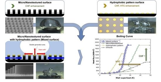
3.3. Synergy of Textured Surfaces with Hydrophobic Patterns

In this study, the surface was fabricated by combining the methods introduced above to simultaneously enhance the CHF and HTC. Micro/nanotextures were fabricated to enhance the CHF by the capillary effect. To generate nucleate bubbles on the top surface of the micropillars, they were coated to provide hydrophobic properties. Figure 8a shows the HTC–wall superheat curve, while Figure 8b shows the boiling curves of the GSB and GSP surfaces. The HTC was enhanced by the high nucleate site density and small contact diameter due to the hydrophobic pattern. Nucleate boiling occurred on the top surface of the micropillar, so that the reintroduced liquid can enter the side and bottom surfaces of the micropillar without disturbance. At the ONB, the wall superheat values of microtextured with gold-SAM (GSM) and micro/nanotextured with gold-SAM (GSMN) surfaces are ~17.9 and ~16.8 K, respectively. Compared to the ONB of GSB and GSP (~8.6 K), the ONB of GSM and GSMN is a high wall superheat. This is considered to be the result of the slow growth of the thermal boundary layer due to thermal conduction to the micropillars, similar to the cases of SiM and SiMN. The HTCs of GSM and GSMN are improved by 101% and 88%, respectively, at 700 kW/m2 near the CHF of SiB. Figure 9 shows bubble images at a heat flux of 200 kW/m2. The numbers of nucleate bubbles per second on SiM and SiMN are ~12 and 2, respectively, whereas those for GSM and GSMN with hydrophobic patterns are increased to ~55 and ~88, respectively. In addition, the departure diameters of the bubble are 8.6 and 25.2 mm for SiM and SiMN, respectively, and approximately 5.2 and 4.8 mm for GSM and GSMN, respectively. Small bubbles nucleated at numerous sites and departed on GSM and GSMN. Therefore, the HTC is enhanced with a high nucleate site density. GSM and GSMN exhibit lower HTCs in all regions that those of GSP. On GSP, bubbles nucleated from the hydrophobic pattern meet hydrophilic surfaces as they grow, whereas, on GSM and GSMN, the bubble growth is predicted to jump from hydrophobic to hydrophobic surfaces beyond liquids. Bubbles with contact diameters smaller than those of SiM and SiMN nucleated because of the pinning effect at the end of the hydrophobic surface on the micropillars, while bubbles larger than those of GSP were nucleated. Therefore, it is presumed that the difference in HTC is due to the changes in the thermal boundary layer caused by the structures and pinning while the bubble grows, which affects the nucleate site density and contact diameter.
Figure 6. Pool boiling experimental data to confirm hydrophobic surface (hydrophobic, patterned hydrophobic) effects. (a) Boiling heat transfer at low heat flux, (b) boiling curve.
Energies 14 07543 g006
Figure 7. Bubble images on the GSB, GSP. GSB has large contact diameter bubbles and early CHF. GSP has smaller contact diameter than GSB due to pinning effect, and can maintain low wall superheat at high heat flux.
Energies 14 07543 g007
Figure 8. Pool boiling experimental data to confirm micro, micro/nanotextured surface with hydrophobic pattern effect. (a) Boiling heat transfer, (b) boiling curve.
Energies 14 07543 g008
Figure 9. Bubble images on the SiM, SiMN, GSM, and GSMN. SiM, SiMN have less nucleate site density, but GSM, GSMN have more nucleate site density than SiM, SiMN.
Energies 14 07543 g009
The CHFs of GSM and GSMN were enhanced to 1560 and 1826 kW/m2, i.e., by 111% and 147% compared to that of SiB, respectively. Similar CHF enhancements were obtained for SiM and SiMN without hydrophobic pattern. However, the HTC was improved by 34% over SiM at 1500 kW/m2 and 42% over SiMN at 1700 kW/m2, which are near the CHFs of GSM and GSMN. The hydrophilic micro- and micro/nanotextured surfaces with hydrophobic patterns fabricated in this study separated the liquid reintroduction path and bubble generation, growth, and departure path, with a higher predicted CHF than that of the surface without the hydrophobic pattern. However, it was considered that a higher CHF was not obtained because the bubble moved very violently and penetrated to the bottom.

4. Conclusions

In this study, we fabricated a micro/nanotextured surface with a hydrophobic pattern to simultaneously enhance CHF and HTC. The diameter of the micropillars and spacing between the pillars were 45 µm, while the height was 20 µm. Random nanostructures were formed on the bottom surface. Gold was coated on the top surface of the micropillars to obtain hydrophobic properties using SAM selectively deposited on gold. This surface was employed in a pool boiling experiment with atmospheric pressure and saturated water. The bubble dynamics were observed using a high-speed camera. The experimental results can be summarized as follows.
  • The micropillars enhanced the CHF by better wetting the dry spots with the capillary-induced flow. The flow was induced by the difference in concaveness at the liquid–vapor interface between the micropillars.
  • The random nanopillars had superhydrophilic properties. Capillary wicking occurred so that dry spots were better wetted and the CHF was enhanced. The wickability of the micro/nanotextured surface was better than those of the micro- and nanotextured surfaces. Therefore, the highest CHF was obtained on the micro/nanotextured surface with the highest wickability.
  • The hydrophobic surface nucleated the bubbles at low surface temperatures. Owing to the large contact diameter, the surface quickly become covered with vapor.
  • The surface with hydrophobic patterns on the hydrophilic surface nucleated the bubbles on the hydrophobic patterns. In addition, as the bubble grew and met the hydrophilic surface, the contact diameter growth was limited because of the pinning effect. Thus, it is possible to enhance the HTC without deteriorating the CHF.
  • To simultaneously enhance the CHF and HTC, the micro/nanotextured surface with hydrophobic patterns (GSMN) was fabricated. With this surface, the CHF was enhanced to 1825 kW/m2, at which a maximum HTC of 65.75 kW/(m2K) was obtained.
  • The GSMN had a high CHF. The HTC was enhanced compared to SiMN without the hydrophobic pattern. However, a lower HTC enhancement was obtained than that of GSP without pillar structures. This could be attributed to the difference in the pinning method. The pillar structures changed the thermal boundary layer.
  • The surface developed in this study can be used for thermal energy systems that require a wide nucleate boiling regime at a low surface temperature.

Author Contributions

H.R.C. Methodology, Formal Analysis, Investigation, Writing—Original draft. S.C.P. Methodology, Formal Analysis, Investigation, Review and editing, Supervision. D.K. Investigation, H.-m.J. Formal Analysis, Review and editing. D.I.Y. Methodology, Formal Analysis, Investigation, Review and editing, Project administration, Funding Acquisition. All authors have read and agreed to the published version of the manuscript.

Funding

This work was supported by a National Research Foundation of Korea (NRF) grant funded by the Korean Government (MSIT) (NRF-2021R1C1C1010589, NRF-2021M2D2A1A01048627).

Institutional Review Board Statement

Not applicable.

Informed Consent Statement

Not applicable.

Data Availability Statement

The data presented in this study are available on request from the corresponding author.

Acknowledgments

We would like to thank SuKon Kim in National Institute for Nanomaterials Technology for helping to fabricate of test sections.

Conflicts of Interest

The authors declare no conflict of interest.

References

  1. Fang, X.; Chen, Y.; Zhang, H.; Chen, W.; Dong, A.; Wang, R. Heat transfer and critical heat flux of nanofluid boiling: A comprehensive review. Renew. Sust. Energ. Rev. 2016, 62, 924–940. [Google Scholar] [CrossRef]
  2. Mudawar, I. Assessment of high-heat-flux thermal management schemes. IEEE Trans. Compon. Packag. Technol. 2001, 24, 122–141. [Google Scholar] [CrossRef]
  3. Liang, G.; Mudawar, I. Review of pool boiling enhancement by surface modification. Int. J. Heat Mass Transf. 2019, 128, 892–933. [Google Scholar] [CrossRef]
  4. Chu, K.H.; Enright, R.; Wang, E.N. Structured surfaces for enhanced pool boiling heat transfer. Appl. Phys. Lett. 2012, 100, 241603. [Google Scholar] [CrossRef]
  5. Kim, D.E.; Yu, D.I.; Park, S.C.; Kwak, H.J.; Ahn, H.S. Critical heat flux triggering mechanism on micro-structured surfaces: Coalesced bubble departure frequency and liquid furnishing capability. Int. J. Heat Mass Transf. 2015, 91, 1237–1247. [Google Scholar] [CrossRef]
  6. Kim, S.H.; Lee, G.C.; Kang, J.Y.; Moriyama, K.; Kim, M.H.; Park, H.S. Boiling heat transfer and critical heat flux evaluation of the pool boiling on micro structured surface. Int. J. Heat Mass Transf. 2015, 91, 1140–1147. [Google Scholar] [CrossRef]
  7. Yu, D.I.; Kwak, H.J.; Noh, H.; Park, H.S.; Fezzaa, K.; Kim, M.H. Synchrotron x-ray imaging visualization study of capillary-induced flow and critical heat flux on surfaces with engineered micropillars. Sci. Adv. 2018, 4, e1701571. [Google Scholar] [CrossRef] [Green Version]
  8. Chen, R.; Lu, M.C.; Srinivasan, V.; Wang, Z.; Cho, H.H.; Majumdar, A. Nanowires for enhanced boiling heat transfer. Nano Lett. 2009, 9, 548–553. [Google Scholar] [CrossRef]
  9. Shim, D.I.; Choi, G.; Lee, N.; Kim, T.; Kim, B.S.; Cho, H.H. Enhancement of pool boiling heat transfer using aligned silicon nanowire arrays. ACS Appl. Mater. Interfaces 2017, 9, 17595–17602. [Google Scholar] [CrossRef] [PubMed]
  10. Nguyen, T.B.; Liu, D.; Kayes, M.I.; Wang, B.; Rashin, N.; Leu, P.W.; Tran, T. Critical heat flux enhancement in pool boiling through increased rewetting on nanopillar array surfaces. Sci. Rep. 2018, 8, 1–9. [Google Scholar]
  11. Ahn, H.S.; Park, G.; Kim, J.M.; Kim, J.; Kim, M.H. The effect of water absorption on critical heat flux enhancement during pool boiling. Exp. Therm. Fluid Sci. 2012, 42, 187–195. [Google Scholar] [CrossRef]
  12. Rahman, M.M.; Olceroglu, E.; McCarthy, M. Role of wickability on the critical heat flux of structured superhydrophilic surfaces. Langmuir 2014, 30, 11225–11234. [Google Scholar] [CrossRef] [PubMed]
  13. Dhillon, N.S.; Buongiorno, J.; Varanasi, K.K. Critical heat flux maxima during boiling crisis on textured surfaces. Nat. Commun. 2015, 6, 1–12. [Google Scholar] [CrossRef] [Green Version]
  14. Kandlikar, S.G. A theoretical model to predict pool boiling CHF incorporating effects of contact angle and orientation. J. Heat Transf. 2001, 123, 1071–1079. [Google Scholar] [CrossRef]
  15. Phan, H.T.; Caney, N.; Marty, P.; Colasson, S.; Gavillet, J. Surface wettability control by nanocoating: The effects on pool boiling heat transfer and nucleation mechanism. Int. J. Heat Mass Transf. 2009, 52, 5459–5471. [Google Scholar] [CrossRef]
  16. Bourdon, B.; Rioboo, R.; Marengo, M.; Gosselin, E.; De Coninck, J. Influence of the wettability on the boiling onset. Langmuir 2012, 28, 1618–1624. [Google Scholar] [CrossRef] [PubMed]
  17. Bourdon, B.; Di Marco, P.; Riobóo, R.; Marengo, M.; De Coninck, J. Enhancing the onset of pool boiling by wettability modification on nanometrically smooth surfaces. Int. Commun. Heat Mass Transf. 2013, 45, 11–15. [Google Scholar] [CrossRef]
  18. Bourdon, B.; Bertrand, E.; Di Marco, P.; Marengo, M.; Rioboo, R.; De Coninck, J. Wettability influence on the onset temperature of pool boiling: Experimental evidence onto ultra-smooth surfaces. Adv. Colloid Interface Sci. 2015, 221, 34–40. [Google Scholar] [CrossRef]
  19. Betz, A.R.; Xu, J.; Qiu, H.; Attinger, D. Do surfaces with mixed hydrophilic and hydrophobic areas enhance pool boiling? Appl. Phys. Lett. 2010, 97, 141909. [Google Scholar] [CrossRef] [Green Version]
  20. Betz, A.R.; Jenkins, J.; Attinger, D. Boiling heat transfer on superhydrophilic, superhydrophobic, and superbiphilic surfaces. Int. J. Heat Mass Transf. 2013, 57, 733–741. [Google Scholar] [CrossRef] [Green Version]
  21. Jo, H.J.; Kim, S.H.; Park, H.S.; Kim, M.H. Critical heat flux and nucleate boiling on several heterogeneous wetting surfaces: Controlled hydrophobic patterns on a hydrophilic substrate. Int. J. Multiph. Flow 2014, 62, 101–109. [Google Scholar] [CrossRef]
  22. Jo, H.J.; Park, H.S.; Kim, M.H. Single bubble dynamics on hydrophobic–hydrophilic mixed surfaces. Int. J. Heat Mass Transf. 2016, 93, 554–565. [Google Scholar] [CrossRef]
  23. Motezakker, A.R.; Sadaghiani, A.K.; Celik, S.; Larsen, T.; Villanueva, L.G.; Koşar, A. Optimum ratio of hydrophobic to hydrophilic areas of biphilic surfaces in thermal fluid systems involving boiling. Int. J. Heat Mass Transf. 2019, 135, 164–174. [Google Scholar] [CrossRef]
  24. Jo, H.J.; Yu, D.I.; Noh, H.; Park, H.S.; Kim, M.H. Boiling on spatially controlled heterogeneous surfaces: Wettability patterns on microstructures. Appl. Phys. Lett. 2015, 106, 181602. [Google Scholar] [CrossRef]
  25. Kim, S.H.; Lee, G.C.; Kang, J.Y.; Moriyama, K.; Park, H.S.; Kim, M.H. Heat flux partitioning analysis of pool boiling on micro structured surface using infrared visualization. Int. J. Heat Mass Transf. 2016, 102, 756–765. [Google Scholar] [CrossRef]
  26. Xiao, R.; Enright, R.; Wang, E.N. Prediction and optimization of liquid propagation in micropillar arrays. Langmuir 2010, 26, 15070–15075. [Google Scholar] [CrossRef]
  27. Jo, H.J.; Ahn, H.S.; Kang, S.; Kim, M.H. A study of nucleate boiling heat transfer on hydrophilic, hydrophobic and heterogeneous wetting surfaces. Int. J. Heat Mass Transf. 2011, 54, 5643–5652. [Google Scholar] [CrossRef]
Figure 5. Capillary wicking test. (a) Wickability of the samples (Wicking distance—Time), (b) spreading images on SiN, SiMN.
Energies 14 07543 g005
Publisher’s Note: MDPI stays neutral with regard to jurisdictional claims in published maps and institutional affiliations.

