Abstract
This paper puts forward a methodology for calculating the duration and energy efficiency of regimes for autoclave steaming of wooden prisms for veneer production at limited heat power of the steam generator, depending on the dimensions of the prism’s cross section, wood moisture content, and loading level of the autoclave. The methodology is based on the use of two personal mathematical models: the 2D non-linear model of the temperature distribution in non-frozen wooden prisms subjected to steaming and subsequent conditioning in an air medium, and the model of the non-stationary heat balance of autoclaves for steaming wood materials. Using the suggested methodology, the calculation and research into the duration and energy efficiency of regimes for heating of beech prisms have been carried out. The variables used were an initial temperature of 0 °C, cross-section dimensions 0.3 × 0.3 m, 0.4 × 0.4 m, and 0.5 × 0.5 m, moisture content of 0.4, 0.6, and 0.8 kg·kg−1, during their steaming in an autoclave with a diameter of 2.4 m, length of 9.0 m and loading level of 40, 50, and 60% at a limited heat power of the steam generator, equal to 500 kW. It has been determined that the duration of the autoclave steaming regimes, at a loading level of 50% being most often used in the practice beech prisms with moisture of 0.6 kg·kg−1, does not exceed 9 h, 13 h, and 20 h for prisms with cross-section 0.3 × 0.3 m, 0.4 × 0.4 m, and 0.5 × 0.5 m, respectively. This duration is less than half of the corresponding duration of the steaming regimes at atmospheric pressure. The energy needed for warming up such prisms themselves does not exceed 60, 65, and 69 kWh·m−3, respectively, and the energy consumption of the whole autoclave then is equal to about 90, 99, and 105 kWh·m−3, respectively. The energy efficiency of the autoclave steaming regimes changes between 62.2% and 68.8% for the studied ranges of the influencing factors and it turns out to be more than 2–3 times larger in comparison with the efficiency of the steaming at atmospheric pressure. The methodology can be used for various calculations with ANSYS and to create the software for systems used for computing and model-based automatic realization of energy-efficient regimes for autoclave steaming of different wood materials from various species. This could be useful in developing similar methodologies in different areas of thermal treatment at increased pressure of various capillary-porous materials of plant or technical origin.
1. Introduction
For plasticizing prismatic wood materials in the production of veneer and plywood, the materials are usually subjected to steaming in different types of equipment which operate at atmospheric or increased pressure [1,2,3,4,5,6,7,8], etc.
The steaming of wood at atmospheric pressure is carried out in pits or in chambers. The steaming under increased pressure of the processing medium in autoclaves is used in many applications due to its higher energy efficiency and lower duration in comparison with the steaming at atmospheric pressure [4,6,9,10,11,12,13,14,15,16,17,18,19].
Information about the duration and energy consumption of steaming wood materials in atmospheric or increased pressure only for the cases of unlimited generator power has been presented in [3,5,20,21,22,23,24,25,26], etc. For example, the following durations of the steaming process at atmospheric pressure at 80 °C of the non-frozen beech prisms considered below with initial temperature of 0 °C and thicknesses of 0.3 m, 0.4 m, and 0.5 m, intended for the production of veneer are equal to 18 h, 28 h, 38 h, respectively [21], or 15 h, 29 h, and 45 h [3].
After 24 h steaming of non-frozen beech prisms with thickness in the range from 0.3 to 0.4 m in good insulated pits, heat energy consumption between 140 kWh∙m−3 and 170 kWh∙m−3 has been measured in [27]. After 28 h boiling of beech prisms in a pit at 80 °C with dimensions of 0.4 × 0.4 × 1.2 m, initial temperature of 10 °C and moisture content of 0.8 kg·kg−1, intended for the production of veneer, the energy consumption and efficiency of 176.2 kWh∙m−3 and of 29.1%, respectively, have been determined in [22]. It has been noted that the energy efficiency of the steaming wood materials in pits is approximately equal to 18% [27]. There is no information in the accessible specialized literature on the availability of verified mathematical models of the heat balance and the energy efficiency of steaming chambers which operate at atmospheric pressure.
The development of correct, efficient and non-defective carrying out of the steaming process in autoclaves depends on the dimensions and initial temperature of the wood materials, on the microstructure specifics and fiber saturation point of the wood species, on the anisotropy of the wood, and on the content and aggregate condition of the water in it. Other important factors are the low change in the temperature of the steaming medium, the design parameters of the autoclave and the degree to which it is loaded with wood materials, the thermo-physical characteristics of the autoclave‘s metal body and insulating layer, and also of the condensed water gathered in the autoclave and of the surrounding air used for subsequent conditioning of the steamed materials. In addition, some of these influencing factors are immeasurable [28]. That is what makes the science-based study and research of the whole complexity of the autoclave steaming process of wood materials possible, only by using adequate mathematical models.
In [12,18], the authors create, numerically solve and validate their own 3D, 2D, and 1D mathematical models for the non-linear heat conduction in anisotropic prismatic wood materials during steaming in autoclaves with the unlimited power of the steam generator.
For small and medium-sized veneer production companies, steaming regimes for wood materials with limited power of the steam generator are of considerable interest. In [28,29], the authors describe an approach for computing the processing medium temperature during steaming of wooden prisms for veneer production in an autoclave at limited power of the steam generator.
This work considers a methodology for using personal mathematical models to compute the duration and energy efficiency of regimes for steaming of non-frozen wooden prisms intended for the production of veneer at limited power of the steam generator, depending mainly on the following influencing factors: dimensions of the prism’s cross section, wood moisture content, and loading level of the autoclave.
2. Materials and Methods
2.1. Material for the Investigations
The good suitability of the models, obtained in [12,18] through industrial experiments on a wide variety of wooden species, allows them—and the approach suggested in [28,29]—to be used for a simulation study of the impact of the above-mentioned three main factors upon the duration and energy efficiency of regimes for autoclave steaming of non-frozen wooden prisms for veneer production at limited power of the steam generator.
The current research has been conducted over non-frozen beech (Fagus sylvatica L.) prismatic materials, which are often subjected to steaming in the practice in order to plasticize in the production of veneer.
During simulations with two of our own models, the following values of the factors influencing the duration and energy efficiency of the prism steaming regimes were set:
- Dimensions of the square cross section of beech prisms with thickness d and width b: 0.3 × 0.3 m, 0.4 × 0.4 m, and 0.5 × 0.5 m.
- Initial moisture content u of the prisms subjected to autoclave steaming: 0.4 kg·kg−1, 0.6 kg·kg−1, and 0.8 kg·kg−1.
- Basic density of 560 kg·m−3 for the beech wood.
- Inner diameter of 2.4 m, length of the cylindrical part of 9.0 m and internal volume of 48 m3 of the steaming autoclave.
- Loading level, γ, of the autoclave with filled in prisms for steaming: 0.4 m3·m−3, 0.5 m3·m−3, and 0.6 m3·m−3 (i.e., γ = 40%, γ = 50%, and γ = 60%, respectively).
- Limited heat power qsource = 500 kW of the generator, which feeds the autoclave with saturated water steam.
- Initial and the maximal values of the steaming medium temperature Tm0 = 273.15 K (i.e., tm0 = 0 °C) and Tm1 = 403.15 K (i.e., tm1 = 130 °C), respectively.
- Temperature of the surrounding environment near the steamed prisms during their conditioning out of the autoclave Tm-cond = 293.15 K (i.e., tm-cond = 20 °C).
2.2. Modelling of the 2D Temperature Distribution in the Wooden Prisms during Their Steaming and Subsequent Conditioning in an Air Medium
It is well known that the moisture diffusion of the wood is hundreds of times smaller than its temperature conductivity. Because of this, it is widely accepted in the theory of wood thermal treatment that the change in temperature of wood materials during their steaming or boiling is a result of a purely thermo-exchange process [1,2,3,4,5,6,12,18,21,30,31,32,33,34,35,36].
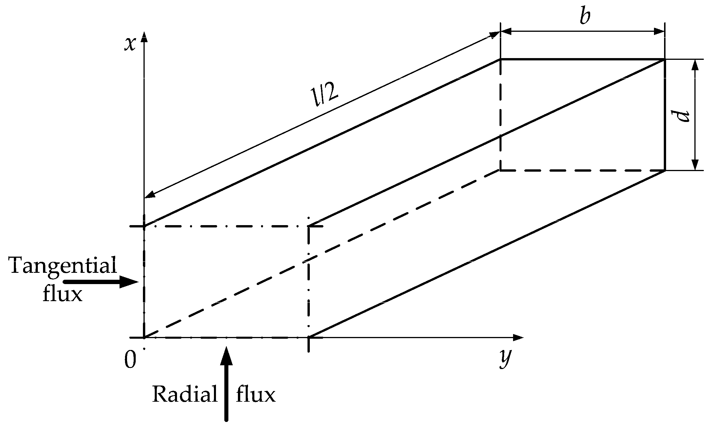
Thus, if the length of the prisms, l, is at least more 4–5 times greater than the thickness, d, and the width, b, is no more than 3 times the thickness, then the non-stationary change in the temperature in the prism’s cross section—which is equally distant from the frontal sides (Figure 1) (i.e., along x and y of this section) during heating and cooling in steaming or air medium with the following 2D model—can be calculated [12,18]:
at
and boundary conditions:
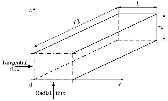
Figure 1.
Positioning of the prism’s dimensions and heat fluxes during the steaming process.
- -
- during the steaming process:
- -
- during the conditioning process of the steamed prisms in an air environment:
The following mathematical descriptions of the change in cw, λr and λt of the non-frozen wood during its heating and cooling have been suggested in [12,13,18,23,37,38], based on the relationships that were experimentally determined in the dissertations of Chudinov [1] and Kanter [39] for the change in c and λ of frozen and non-frozen wood as a function of t and u.
With the help of numerous real and model experiments in [6,12,18,23], the precise values of the coefficient Kad in Equation (8) for different anatomical directions and wood species have been determined. For the beech wood discussed in this paper, the following values of this coefficient in radial Kad-r = 1.35 and in tangential Kad-t = 1.21 directions have been obtained. The experiments at increased pressure have shown that the influence of the gaps between prisms in a given autoclave batch on the temperature distribution in the separate prisms is negligible.
It must be noted that the experimentally derived data for and in [1,39] are widely used in both the European [3,4,5,6,20,21,40,41] and the American specialized literature [30,31,32,33,34,35,36] when calculating various processes of wood steaming and boiling.
The wood density ρw, which participates in Equation (1), is determined above the hygroscopic range according to the below equation [3,4,12,18,20,42,43]:
In [6,12], the following dependence for computing the convective heat transfer coefficient between steamed wood materials and surrounding air has been experimentally received:
where τreg is the duration of the steaming regimes, s.
2.3. Modelling of the Heat Energy Consumption and Energy Efficiency of Autoclaves
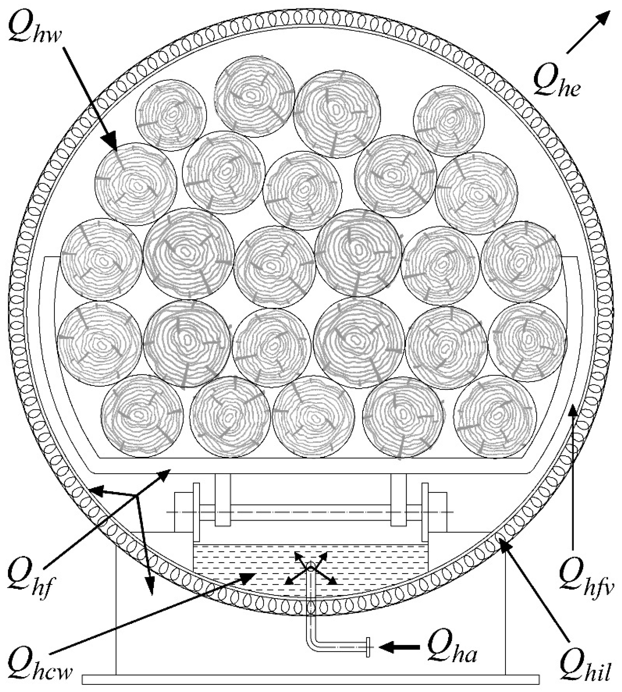
On the grounds of energy analyses, the structural model, presented in Figure 2, of distribution of the energy consumption of autoclaves for steaming wood materials of different shape and applications has been created [12].
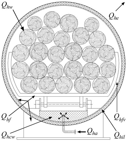
Figure 2.
Structural model of the heat distribution in an autoclave for steaming of wood.
The non-stationary heat balance of the steaming autoclave can be mathematically described by the following model, which has been experimentally verified in [12]:
where Qha is the specific (for 1 m3 wood) heat energy, which is supplied into the autoclave, kWh·m−3; Qhw—energy used for heating of the subjected to steaming wood materials, kWh·m−3; Qhf—energy used for heating of the autoclave’s body and the metal trolleys in it, kWh·m−3; Qhil—energy used for heating of the insulating layer of the autoclave, kWh·m−3; Qhe—energy used for heat emission, kWh·m−3; Qhfv—energy used for filling in with steam of the autoclave’s free volume, kWh·m−3; Qhcw—energy, which is accumulated in the condense water, kWh·m−3; n—time coordinate, which is used to numerically solve the models in Equations (1)–(13).
Mathematical descriptions of all components of the heat balance in Equation (13), depending on the influencing factors, have been given in [6,12] as follows: Qhw = f[cw(x,y,τ), ρw, Tw0, Tw(x,y,τ), Tw-avg, Sw], Qhf = f[cf, ρf, Vf, Tm0, Tm(τ), Va, γ], Qhil = f[cil(z,τ), ρil, Til0, Til(z,τ), dil, Va, γ], Qhe = f[Fil, Fs, T(dil,τ), Tair(τ) αil(τ), αs(τ), Va, γ], Qhfv = f[ρv(τ), Va, γ], Qhcw = f[mcw(τ), hcw(Tm,τ), Va, γ].
The meaning of the variables in these dependences, whose explanation is not given under Equation (5), is, as follows: Sw—area of the prism’s cross section, m2; cs and cil—heat capacities of the autoclave’s steel body and insulating layer, respectively, J·kg−1·K−1; ρf and ρv—density of the autoclave’s steel body and the water steam in the autoclave, respectively, kg·m−3; Tw-avg—average mass temperature of the prisms, K; Tm0 and Til0—initial temperature in the autoclave and of the insulating layer, respectively, K; Tair—temperature of the air near the autoclave, K; Va—internal volume of the autoclave, m3; γ—loading level of the with filled in prisms for steaming, m3·m−3; z—coordinate along the thickness of the insulating layer in 1D model of its unsteady heating, m; dil—thickness of the insulating layer, m; Fil and Fs—aria of the insulating layer and of the uninsulated autoclave’s surfaces, respectively, m2; αil and αs—convective heat transfer coefficient between the ambient air and insulated layer and uninsulated autoclave’s surfaces, respectively, W·m−2·K−1; mcw—mass of the condensed water in the autoclave, kg; hcw—enthalpy of the condensed water which is gathered in the autoclave, J·kg−1; τ—time, s.
In [44], the following mathematical description of for prismatic wood materials is given:
Using this description and also the description of , it is possible to calculate the current value of the energy efficiency (in %) of different regimes for autoclave steaming of wood materials, η, according to the following equation:
2.4. Change in the Processing Medium Temperature Tm in Regimes for Steaming of Prisms in an Autoclave and for Their Subsequent Conditioning
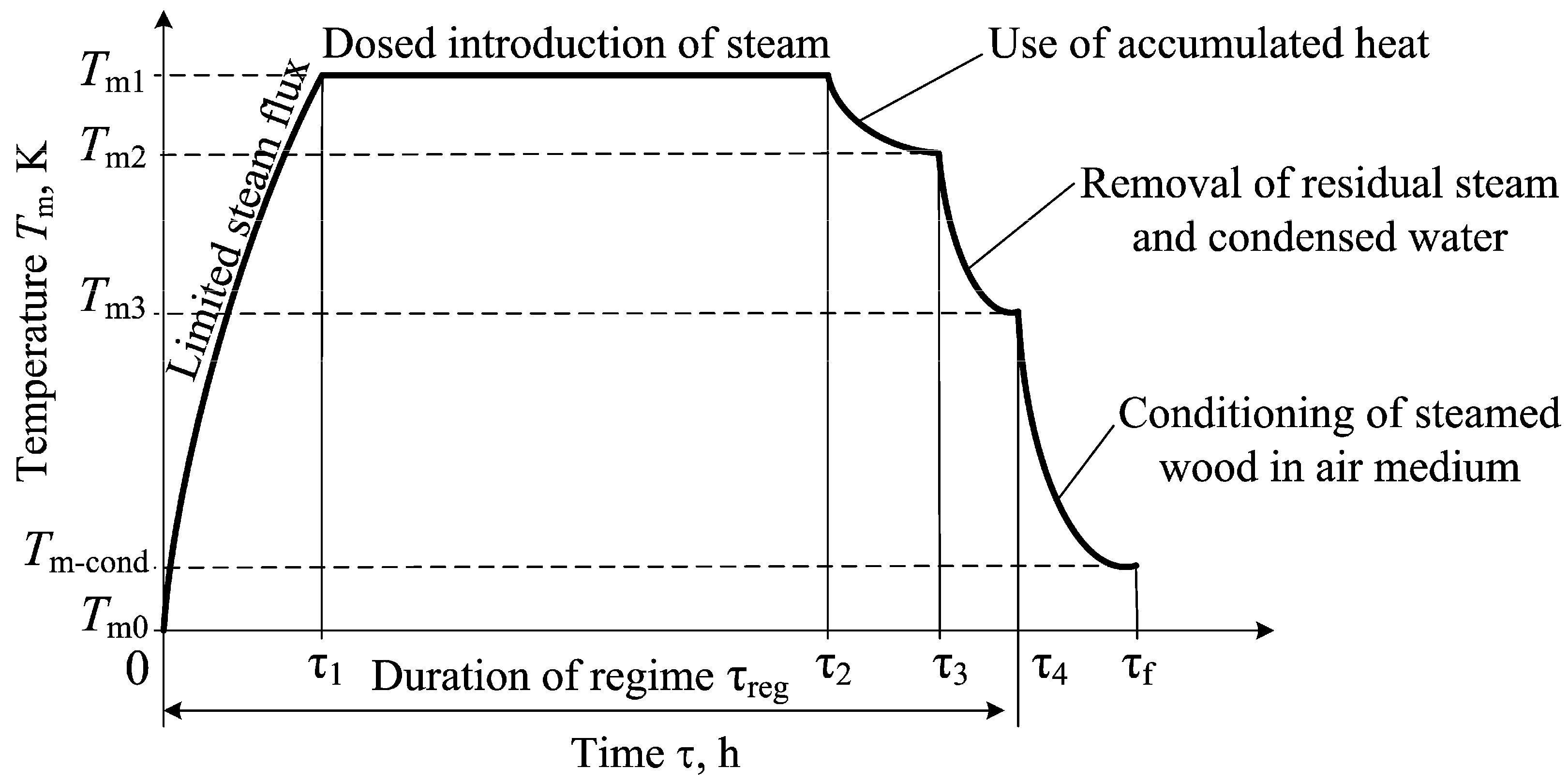
The typical change in Tm in regimes for autoclave steaming of wooden prisms and their subsequent conditioning in air environment, which was used during the numerical simulations below, is shown in Figure 3. These regimes contain five stages [8]:
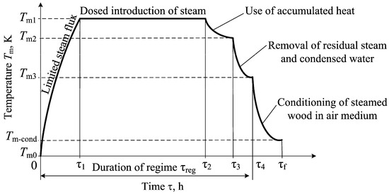
Figure 3.
Typical change in Tm during steaming of prisms in an autoclave and air conditioning.
- Intensive increasing of Tm during the time 0–τ1, which is caused by the full opening of the valve directing the water steam in the autoclave. An intensive increase in Qhfv during this stage occurs, but the rest of the components of the autoclave’s heat balance then change slowly.
- Constant Tm of the steaming medium during τ1–τ2 caused by dosed introduction of water steam in the autoclave. During this stage of the regime, the largest heating of the prisms takes place and a gradual increase in Qhw, Qhil, Qhe, and Qhcw occurs. At the same time, the energy Qhfv remains unchanged. After reaching a certain value of Tw-avg at τ2, the supply of water steam to the autoclave is stopped. The calculated values of Qhw and Qha at τ2 are used below to determine η for each of the studied regimes for prisms autoclave steaming.
- Decreasing Tm of the steaming medium during τ2–τ3 caused by using the already accumulated heat in the autoclave.
- Decreasing Tm of the steaming medium during τ3–τ4, which is caused by the opening the cranes directing the steam and condensed water out of the autoclave.
- Decreasing Tm of the air near the steamed prisms out of the autoclave during τ4–τf.
The time from 0 to τ4 represents the duration of the regime for autoclave steaming of the prisms, τreg.
3. Results and Discussion
In order to numerically solve the models aiming to calculate the duration and energy efficiency of the autoclave steaming regimes of prisms for veneer production at limited power of the steam generator, a software package was prepared, which was input in the platform of Visual FORTRAN developed by the world famous American company Microsoft.
In order to transform the models into a form suitable for programming in FORTRAN, an explicit form of the finite-difference method was used, which excludes any simplification of the unsteady models [6,18,21,23,28]. During the simulations with the two experimentally verified models presented above, the factors influencing the duration and energy efficiency of the prisms steaming regimes, listed in Section 2.1, were used.
With the help of the software package, simulations were made to compute the Tm and also the 2D unsteady change in the temperature in the square cross section of the studied beech prisms during their steaming in an autoclave. The coordinates of the characteristic points of the prisms, in which the change in T was recorded, were equal, as follows: Point 1 with T1: d/8, b/8 and Point 2 with T2: d/2, b/2 (center of the prisms).
At the same time, the average mass temperature of the prisms, Tavg, the energy needed to warm them, Qhw, and the entire energy consumed by the autoclave, Qha, were calculated. For this purpose, using Equation (11), the following values of the wood density of the subjected to autoclave steaming beech prisms were applied: ρw = 784 kg·m−3 for u = 0.4 kg·kg−1, ρw = 896 kg·m−3 for u = 0.6 kg·kg−1, and ρw = 1008 kg·m−3 for u = 0.8 kg·kg−1.
Using the obtained values of Qhw and Qha, the energy efficiency of the steaming regimes was determined according to Equation (15).
3.1. Computing the Unsteady 2D Temperature Distribution in Prisms during Autoclave Steaming and Consequent Conditioning
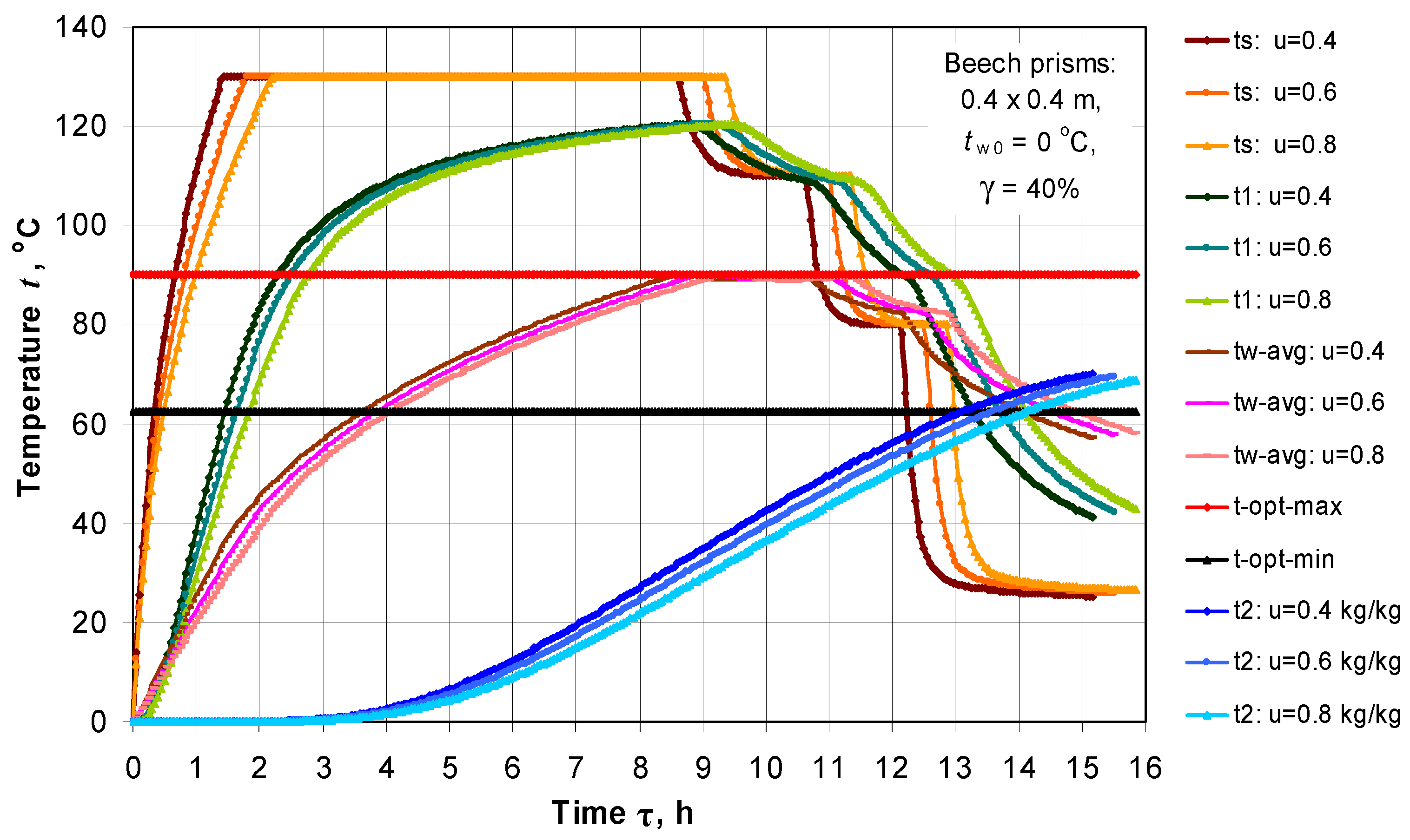
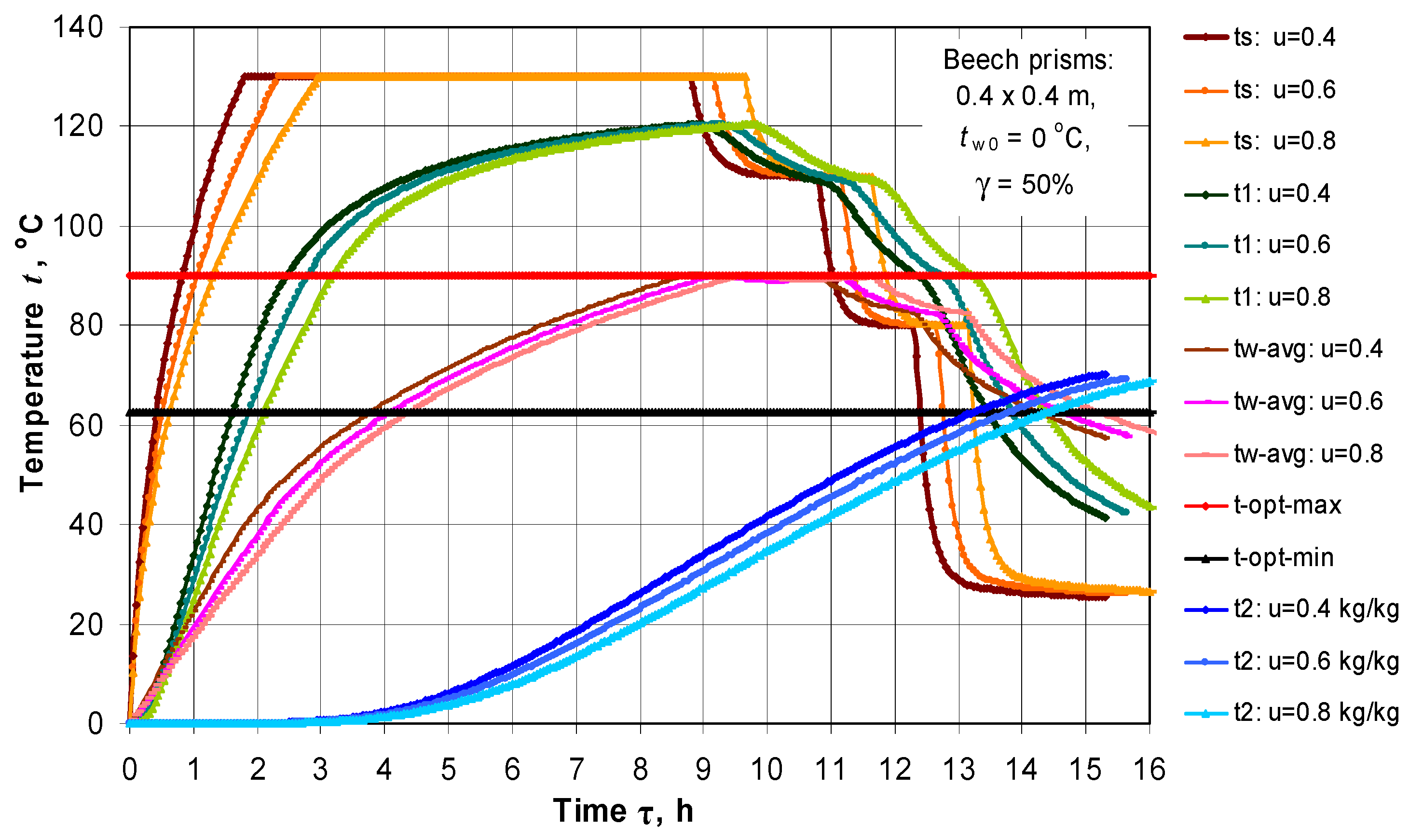
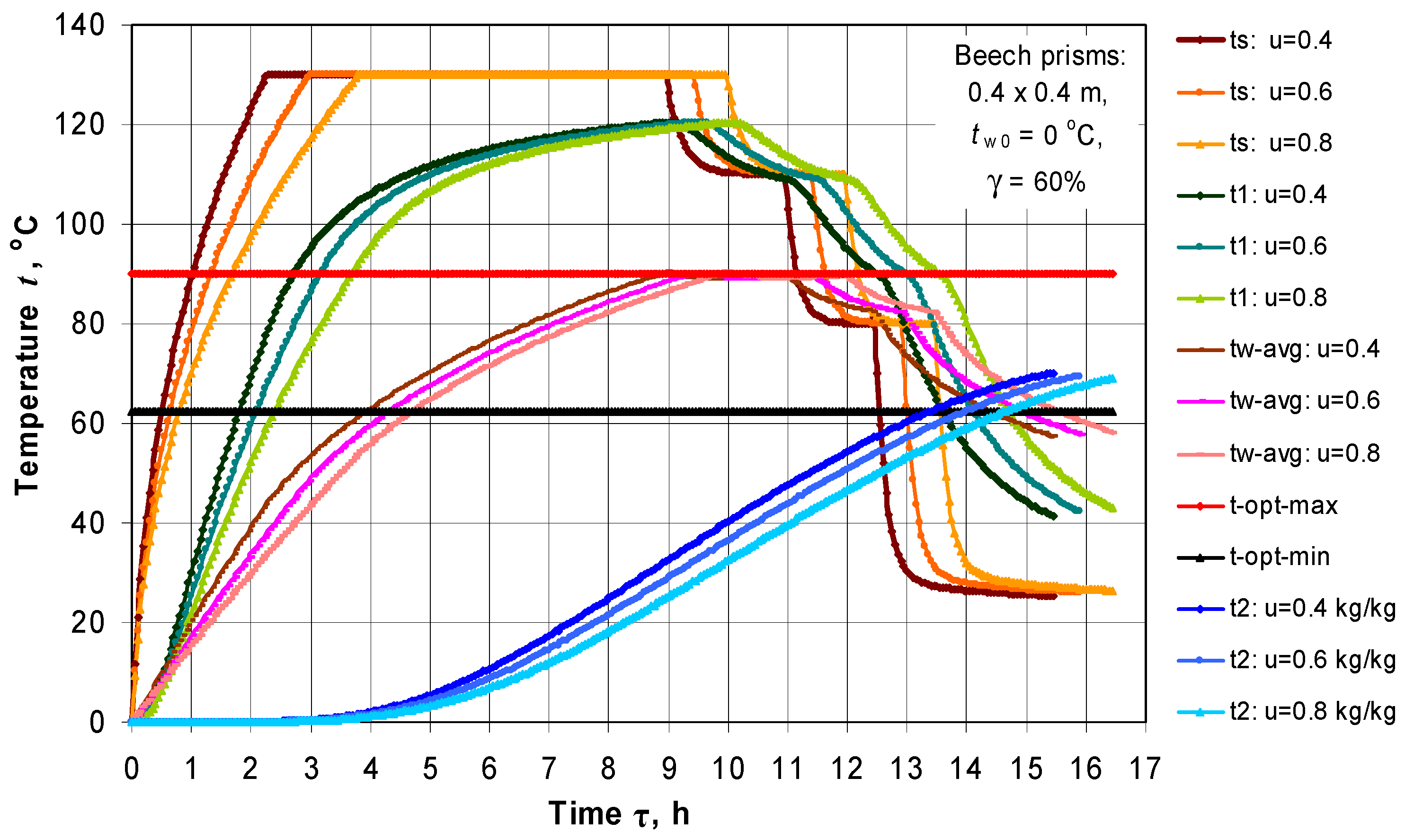
In Figure 4, Figure 5 and Figure 6, the calculated changes in the surface temperature, ts, average mass temperature, tw-avg, and t of 2 characteristic points t1 and t2) of the beech prisms with d × b = 0.4 × 0.4 m, moisture content u = 0.4, 0.6, 0.8 kg·kg−1, and loading level of the autoclave γ = 40%, 50%, 60%, respectively, during their autoclave steaming and subsequent conditioning are presented.
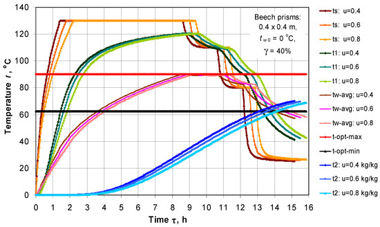
Figure 4.
Changes in ts, tw-avg, and t in 2 characteristic points t1 and t2 of the prisms with d × b = 0.4 × 0.4 m and γ = 40% during their steaming in an autoclave and subsequent conditioning, depending on u and τ.
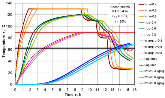
Figure 5.
Changes in ts, tw-avg, and t in 2 characteristic points t1 and t2 of the prisms with d × b = 0.4 × 0.4 m and γ = 50% during their steaming in an autoclave and subsequent conditioning, depending on u and τ.
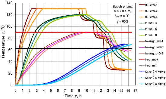
Figure 6.
Changes in ts, tw-avg, and t in 2 characteristic points t1 and t2 of the prisms with d × b = 0.4 × 0.4 m and γ = 60% during their steaming in an autoclave and subsequent conditioning, depending on u and τ.
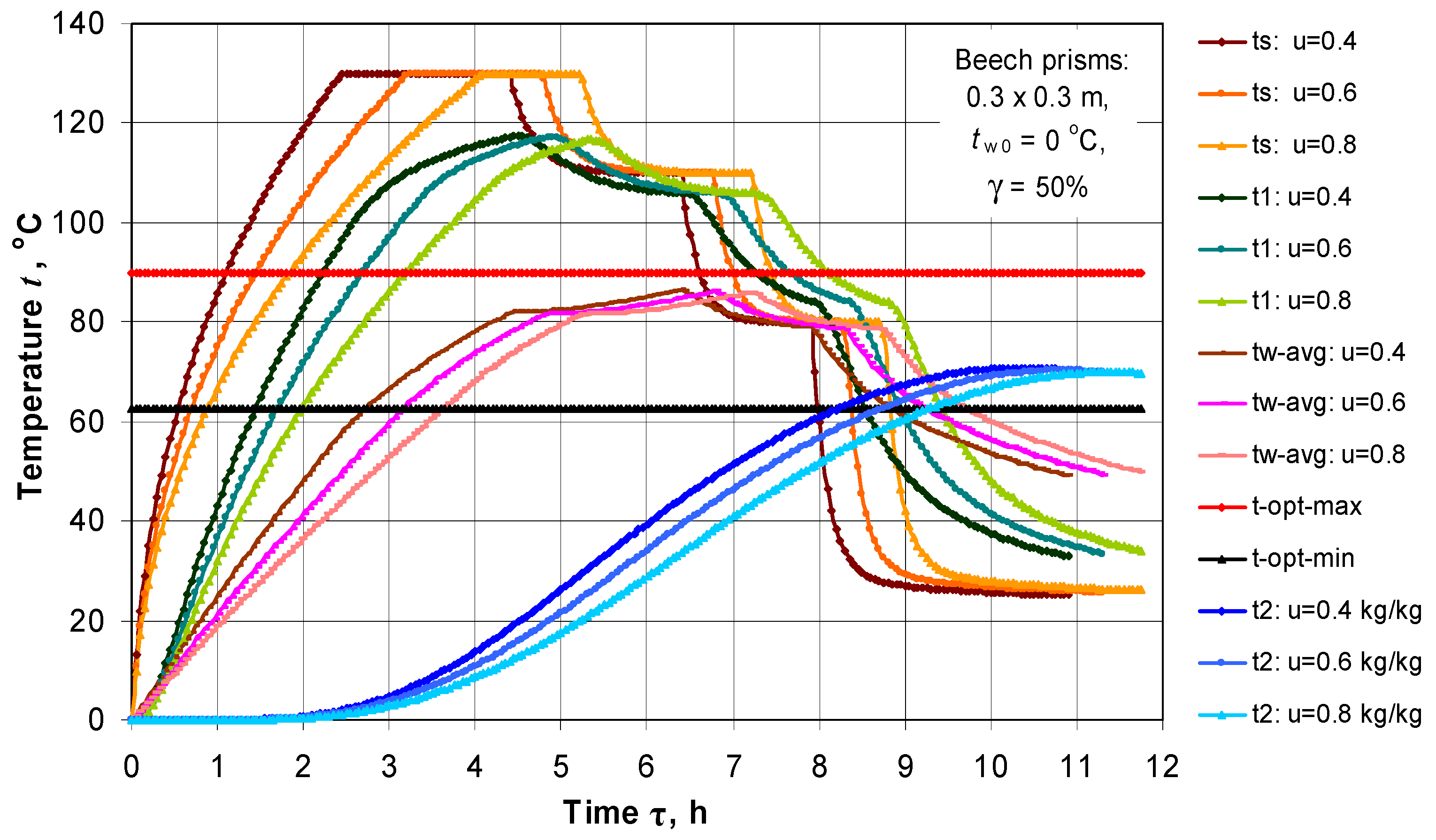
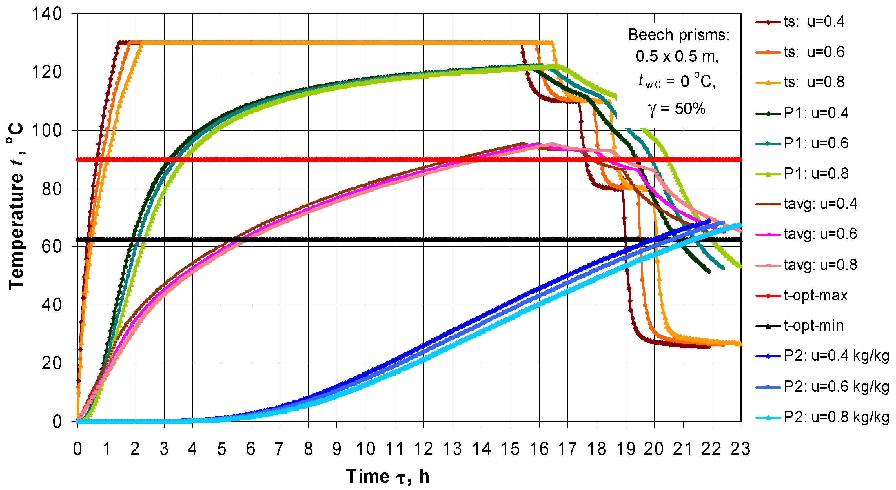
The change in ts, t1, t2, and tw-avg during the steaming of prisms with intermediate values u = 0.6 kg∙kg−1, and γ = 50%, and d × b = 0.3 × 0.3 m and d × b = 0.5 × 0.5 m is shown in Figure 7 and Figure 8, respectively.
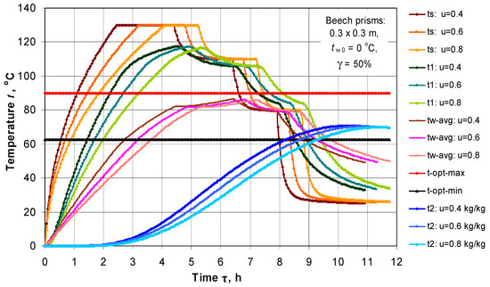
Figure 7.
Changes in ts, tw-avg, and t in 2 characteristic points t1 and t2 of the prisms with d × b = 0.3 × 0.3 m during their steaming in an autoclave at γ = 50% and subsequent conditioning, depending on u and τ.
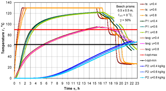
Figure 8.
Changes in ts, tw-avg, and t in 2 characteristic points t1 and t2 of the prisms with d × b = 0.5 × 0.5 m during their steaming in an autoclave at γ = 50% and subsequent conditioning, depending on u and τ.
In these figures, the minimal and maximal values of the temperature, topt-min = 62 °C and topt-max = 90 °C, respectively, are also shown. In order to obtain quality veneer from plasticized beech wood, the temperature of all characteristic points of the prisms during the veneer cutting process must stay between these optimal values of the temperature [6,12,19].
The temperatures in the figures, and in the analyses below, are given in °C instead in K, which is more convenient for understanding and practical use.
Carrying out calculation of the temperature distribution in the prisms has been interconnected for the processes of their steaming in an autoclave and their subsequent conditioning in an air environment.
Table 1 shows the changes in the duration of the stages τ2, τ3 and τ4 (see Figure 3), the temperatures t1 at τ1 and t4 at τ4, and also after 1 h conditioning (at τ4 + 1 h) and after 2 h conditioning (at τ4 + 2 h) of prisms with d × b = 0.4 × 0.4 m.

Table 1.
Changes in the Duration of the Steaming Regimes τreg for Autoclave Steaming at tm1 = 130 °C of Beech Prisms with tw0 = 0 °C and d × b = 0.4 × 0.4 m, Depending on Moisture Content u and Loading Level γ.
The same parameters of prisms with d × b = 0.3 × 0.3 m and d × b = 0.5 × 0.5 m but only at the intermediate value of γ = 50% are presented in Table 2.

Table 2.
Change in the Duration of the Steaming Regimes τreg for Autoclave Steaming at tm1 = 130 °C and γ = 50% of Beech Prisms with tw0 = 0 °C, d × b = 0.3 × 0.3 m and d × b = 0.5 × 0.5 m, Depending on u.
The obtained results, some of which are presented above, have led us to making the following statements about the change in the duration of the regimes for plasticizing of beech prisms, τreg, in an autoclave with inner diameter of 2.4 m, length of its cylindrical part of 9.0 m, and inner volume of 48 m3, depending on the studied influencing factors:
- The increase in the prisms’ dimensions at given values of u and γ causes non-linear increase in τreg. For example, at the most often used in the practice variables of u = 0.6 kg·kg−1, and γ = 50%, the duration τreg at tm1 = 130 °C (see Figure 3) and qsource = 500 kW obtains the following values: 8.25 h for prisms 0.3 × 0.3 m; 12.70 h for prisms 0.4 × 0.4 m, and 19.40 h for prisms 0.5 × 0.5 m.
- The increase in the prisms’ moisture content from 0.4 to 0.8 kg·kg−1 at given values of d × b and γ causes an insignificant, practically linear increase in τreg. When d × b = 0.4 × 0.4 m and γ = 50%, the duration τreg at tm1 = 130 °C and qsource = 500 kW is equal as follows: 12.30 h for u = 0.4 kg·kg−1, 12.70 h for u = 0.6 kg·kg−1, and 13.15 h for u = 0.8 kg·kg−1.
- The increase in the loading level of the autoclave from 40 to 60% at given values of d × b and u causes a slight linear increase in τreg. When d × b = 0.4 × 0.4 m, and u = 0.6 kg·kg−1 the duration τreg at tm1 = 130 °C and qsource = 500 kW obtains the following values: 12.50 h for γ = 40%, 12.70 h for γ = 50%, and 12.90 h for γ = 60% (Table 1).
- It can be seen on Figure 4, Figure 5, Figure 6, Figure 7 and Figure 8 and Table 1 and Table 2 that the temperatures of the studied characteristic points near the prisms surfaces (t1) and in the prisms center (t4) enter between topt-min = 62 °C and topt-max = 90 °C after duration of the conditioning of the steamed prisms at tm-cond = 20 °C (see Figure 3) in an air environment equal to approximately 30 min (i.e., τ4 + 0.5 h) when d × b = 0.3 × 0.3 m, to 60 min (i.e., τ4 + 1 h) when d × b = 0.4 × 0.4 m, and to approximately 120 min (i.e., τ4 + 2 h) when d × b = 0.5 × 0.5 m.
It must be noted that the impact of the prism’s dimensions d × b and γ on the duration τ1 (refer to Figure 3) in the beginning of the steaming regimes at a given value of qsource has been already considered and explained in [29].
The results obtained in the present paper show that the increase in the wood moisture content, u, practically caused a linear increase in τ1. The reason for this is that the larger wood moisture content means there is a larger capacity of the wood subjected to steaming in the autoclave. Because of that, a smaller increase in tm during any next time step Δτ of the models’ solving is calculated.
3.2. Computing the Energy Efficiency of the Regimes for Steaming Prisms in an Autoclave
In Table 3, the calculated by Equation (15) change in the energy efficiency η of the presented on Figure 4, Figure 5 and Figure 6 regimes for autoclave steaming of beech prisms is given. The values of η are determined for the time τ2 of the steaming regimes (see Figure 3) when the supply of water steam in the autoclave is terminated.

Table 3.
Change in the Energy Efficiency η of the Regimes for Autoclave Steaming at tm1 = 130 °C of Beech Prisms with two = 0 °C and d × b = 0.4 × 0.4 m, Depending on Moisture Content u and Loading Level γ.
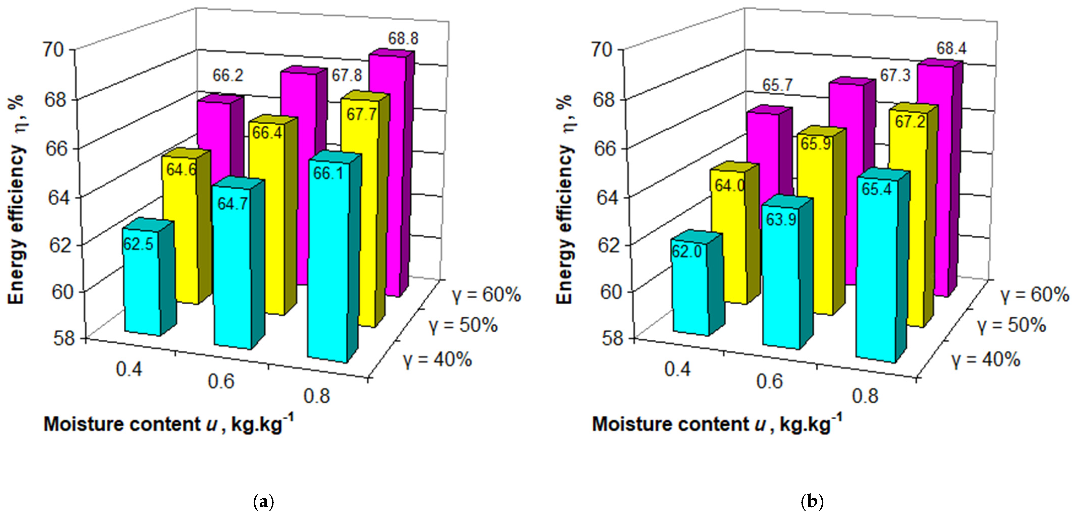
The analogous values of η for prisms with d × b = 0.3 × 0.3 m and d × b = 0.5 × 0.5 m steamed only at γ = 50% are given in Table 4. All calculated values of η are graphically presented in Figure 9.

Table 4.
Change in the Energy Efficiency η of the Regimes for Autoclave Steaming at tm1 = 130 °C and γ = 50% of Beech Prisms with tw0 = 0 °C, d × b = 0.3 × 0.3 m and d × b = 0.5 × 0.5 m, Depending on u.
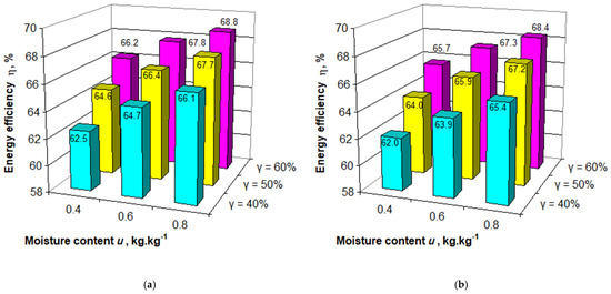
Figure 9.
Change in η of regimes for steaming at tm1 = 130 °C of beech prisms with tw0 = 0 °C, d × b = 0.3 × 0.3 m (a), and d × b = 0.5 × 0.5 m (b) in an autoclave with D = 2.4 m and L = 9 m, depending on u and γ.
The analysis of the received simulation results allows us to make the following statements about the change in η of the regimes for plasticizing beech prisms in an autoclave with inner diameter of 2.4 m, length of its cylindrical part of 9.0 m, and inner volume of 48 m3, depending on the studied influencing factors:
- The increase in the prisms dimensions at given values of u and γ causes a slight reduction of η. For example, when u = 0.6 kg·kg−1 and γ = 50% the efficiency η at tm1 = 130 °C obtains the following values: 66.4% for prisms 0.3 × 0.3 m; 66.1% for 0.4 × 0.4 m, and 65.9% for 0.5 × 0.5 m.
- The increase in u from 0.4 to 0.8 kg·kg−1 at given values of d × b and γ causes an increase in η within a maximum of 4%. When d × b = 0.4 × 0.4 m and γ = 50%, the efficiency η at tm1 = 130 °C is equal as follows: 64.3% for u = 0.4 kg·kg−1, 66.1% for u = 0.6 kg·kg−1, and 67.4% for u = 0.8 kg·kg−1.
- The increase in γ from 40 to 60% at given values of d × b and u also causes an increase in η within a maximum of 4%. When d × b = 0.4 × 0.4 m and u = 0.6 kg·kg−1 the efficiency η at tm1 = 130 °C. the following values are obtained: 64.2% for γ = 40%, 66.1% for γ = 50%, and 67.5% for γ = 60%.
4. Conclusions
The present paper describes a methodology for calculating the duration and energy consumption and efficiency of regimes for autoclave steaming of wooden prisms intended for the production of veneer, τreg, Qha, and η, respectively, at limited heat power of the steam generator, depending on the separate combinations between the following influencing factors: dimensions of the prism’s cross section, d × b, wood moisture content u, and loading level of the autoclave, γ.
The methodology is based on the use of two personal mathematical models: 2D non-linear model of the unsteady distribution of t in non-frozen prismatic wood materials subjected to steaming and subsequent conditioning in an air environment, and model of the non-stationary heat balance of autoclaves for steaming wood materials.
For numerical solving of the models and practical application of the suggested methodology for the calculation of τreg and η, a software package was prepared in the platform of Visual FORTRAN developed by Microsoft.
The paper presents and analyses tables and diagrams of the non-stationary 2D temperature distribution and of the change that is dependent on it in τreg and η of beech prisms with cross-section dimensions 0.3 × 0.3 m, 0.4 × 0.4 m, and 0.5 × 0.5 m, initial temperature of 0 °C, basic density of 560 kg·m−3, moisture content of 0.4, 0.6, and 0.8 kg·kg−1, during their steaming in an autoclave with inner diameter of 2. 4 m, length of its cylindrical part of 9.0 m and loading level of 40, 50, and 60% at a limited heat power of the steam generator, equal to 500 kW.
It has been found that the increase in the cross-section dimensions of the prisms at given values of u and γ causes a non-linear increase in τreg and a slight reduction in η. The increase in u at given values of d × b and γ causes insignificant linear increase in τreg and almost proportional increase in η within a maximum of 4%. The increase in γ at given values of d × b and u causes a slight linear increase in τreg and an increase in η within maximum of 4%.
Numerous data points for τreg and η, depending on different combinations of d × b, u, and γ, have been given in the paper. According to these, the durations of the autoclave steaming regimes at γ = 50% for the beech prisms most often used in the practice with u = 0.6 kg·kg−1 do not exceed 9 h for prisms with d × b = 0.3 × 0.3 m, 13 h for prisms with d × b = 0.4 × 0.4 m, and 20 h for prisms with d × b = 0.5 × 0.5 m. This duration is less than half of the corresponding duration of the steaming regimes at atmospheric pressure.
The energy needed for warming up such prisms, Qhw, does not exceed 60, 65, and 69 kWh∙m−3, respectively, and the energy consumption of the whole autoclave, Qha, then is equal to about 90, 99, and 105 kWh·m−3, respectively.
The energy efficiency of the autoclave steaming regimes turns out to be more than 2–3 times larger in comparison to the efficiency of steaming at atmospheric pressure, and for the studied ranges of the influencing factors, it changes between 62.5% and 68.8% for prisms with d × b = 0.3 × 0.3 m, between 62.2% and 68.6% for prisms with d × b = 0.4 × 0.4 m, and between 62.2% and 68.4% for prisms with d × b = 0.5 × 0.5 m.
The suggested methodology and the equations presented above can be applied to calculate—with the help of the commercially available multi-purpose software product ANSYS—energy effective autoclave steaming regimes, depending on the influencing factors. This methodology can also be used to create the software of systems for the calculating and model-based automatic creation of optimized regimes for autoclave steaming of different wood materials from various species at limited power of the steam generator.
This methodology could be useful in developing similar methodologies in different areas of thermal treatment at increased pressure of various capillary-porous materials of plant or technical origin.
Author Contributions
Conceptualization, N.D., L.D. and D.A.; methodology, N.D. and L.D.; software, N.D.; validation, N.D., L.D. and N.T.; formal analysis, L.D. and N.D.; investigation, N.D., L.D. and D.A.; resources, L.D., N.D. and D.A.; data curation, N.D. and N.T.; writing—original draft preparation, N.D., L.D. and D.A.; writing—review and editing, N.D. and D.A.; visualization, N.T. and N.D.; supervision, N.D.; project administration, L.D.; funding acquisition, L.D. All authors have read and agreed to the published version of the manuscript.
Funding
This research received no external funding.
Institutional Review Board Statement
Not applicable.
Informed Consent Statement
Not applicable.
Acknowledgments
This document was supported by the APVV Grant Agency as part of the project: APVV-17-0456 as a result of work of authors and the considerable assistance of the APVV agency.
Conflicts of Interest
The authors declare no conflict of interest.
References
- Chudinov, B.S. Theoretical Research of Thermo-Physical Properties and Thermal Treatment of Wood. Dissertation for DSc., SibLTI, Krasnoyarsk, Russia, 1966. [Google Scholar]
- Kollmann, F.F.; Côté, W.A., Jr. Solid wood. In Principles of Wood Science and Technology; Springer: New York, NY, USA; Berlin/Heidelberg, Germany, 1984; 592p. [Google Scholar]
- Shubin, G.S. Drying and Thermal Treatment of Wood; Lesnaya Promyshlennost: Moscow, Russia, 1990; 337p. [Google Scholar]
- Trebula, P.; Klement, I. Drying and Hydrothermal Treatment of Wood; Technical University in Zvolen: Zvolen, Slovakia, 2002; 449p. [Google Scholar]
- Pervan, S. Technology for Treatment of Wood with Water Steam; University in Zagreb: Zagreb, Croatia, 2009. [Google Scholar]
- Deliiski, N.; Dzurenda, L. Modelling of the Thermal Processes in the Technologies for Wood Thermal Treatment; Technical University in Zvolen: Zvolen, Slovakia, 2010; 224p. [Google Scholar]
- Niemz, P.; Sonderegger, W. Holzphysik: Physik des Holzes und der Holzwerkstoffe; Carl Hanser Verlag GmbH & Company KG: Munich, Germany, 2017; 580p. [Google Scholar]
- Hadjiski, M.; Deliiski, N.; Tumbarkova, N. Intelligent Hybrid Control of Thermal Treatment Processes of Wood. In Proceedings of the IEEE 10th International Conference on Intelligent Systems, IS 2020, Varna, Bulgaria, 28–30 August 2020; pp. 482–489. [Google Scholar]
- Burtin, P.; Jay-Allemand, C.; Charpentier, J.P.; Janin, G. Wood Colour and Phenolic Composition under Various Steaming Conditions. Holzforschung 2000, 54, 33–38. [Google Scholar] [CrossRef]
- Riehl, T.; Welling, J.; Frühwald, A. Druckdämpfen von Schnittholz; Arbeitsbericht 2002/01; Institut für Holzphysik, Bundesforschungsanstalt für Forst- und Holzwirtschaft: Hamburg, Germany, 2002. [Google Scholar]
- Bekhta, P.; Niemz, P. Effect of High Temperature on the Change in Color, Dimensional Stability and Mechanical Properties of Spruce Wood. Holzforschung 2003, 57, 539–546. [Google Scholar] [CrossRef]
- Deliiski, N. Modelling and Technologies for Steaming Wood Materials in Autoclaves. Dissertation for DSc., University of Forestry, Sofia, Bulgaria, 2003; 358p. [Google Scholar]
- Deliiski, N. Modelling and Automatic Control of Heat Energy Consumption Required for Thermal Treatment of Logs. Drvna Ind. 2004, 55, 181–199. [Google Scholar]
- Deliiski, N.; Sokolovski, S. Autoclaves for Intensive Resource Saving Steaming of Wood Materials. In Proceedings of the 2nd International Scientific Conference “Woodworking Techniques”, Zalesina, Croatia, 11–15 September 2007; pp. 19–26. [Google Scholar]
- Sokolovski, S.; Deliiski, N.; Dzurenda, L. Constructive Dimensioning of Autoclaves for Treatment of Wood Materials under Pressure. In Proceedings of the 2nd International Scientific Conference “Woodworking Techniques”, Zalesina, Croatia, 11−15 September 2007; pp. 117–126. [Google Scholar]
- Dagbro, O.; Torniainen, P.; Karlsson, O.; Morén, T. Colour Responses from Wood, Thermally Modified in Superheated Steam and Pressurized Steam Atmospheres. Wood Mater. Sci. Eng. 2010, 5, 211–219. [Google Scholar] [CrossRef]
- Deliiski, N. Model Based Automatic Control of the Wood Steaming Process in Autoclaves. In Proceedings of the 4th International Science Conference “Woodworking Techniques”, Prague, Czech Republic, 7−10 September 2011; pp. 67–72. [Google Scholar]
- Deliiski, N. Transient Heat Conduction in Capillary Porous Bodies. In Convection and Conduction HeatTransfer; Ahsan, A., Ed.; InTech Publishing House: Rieka, Croatia, 2011; pp. 149–176. [Google Scholar]
- Deliiski, N.; Dzurenda, L.; Trichkov, N.; Tumbarkova, N. Computing the 2D Temperature Field in Non-Frozen Logs at Changing Atmospheric Temperature and during their Subsequent Autoclave Steaming. Acta Fac. Xylologiae Zvolen 2020, 62, 47–59. [Google Scholar]
- Chudinov, B.S. Theory of the Thermal Treatment of Wood; Nauka: Moscow, Russia, 1968; 255p. [Google Scholar]
- Lawniczak, M. Hydrothermal and Plasticizing Treatment of Wood. Part I. Boiling and Steaming of Wood; Agricultural Academy: Poznan, Poland, 1995; 149p. [Google Scholar]
- Dzurenda, L.; Deliiski, N. Mathematical Model for Calculation Standard Values for Heat Energy Consumption during the Plasticization Process of Wood Logs and Prisms by Hot Water in Pits. Acta Fac. Xylologie Zvolen 2011, 53, 25–36. [Google Scholar]
- Deliiski, N. Modelling of the Energy Needed for Heating of Capillary Porous Bodies in Frozen and Non-Frozen States; Lambert Academic Publishing, Scholars’ Press: Saarbrücken, Germany, 2013; 106p. [Google Scholar]
- Deliiski, N.; Dzurenda, L.; Brezin, V. Calculation of the Heat Energy Needed for Melting of the Ice in Wood Materials for Veneer Production. Acta Fac. Xyilologiae Zvolen 2013, 55, 21–32. [Google Scholar]
- Konopka, A.; Chuchala, D.; Orlowski, K.A.; Vilkovská, T.; Klement, I. The Effect of Beech Wood (Fagus sylvatica L.) Steaming Process on the Colour Change versus Depth of Tested Wood Layer. Wood Mater. Sci. Eng. 2021. [Google Scholar] [CrossRef]
- Moya, R.; Tenorio, C.; Torres, J.D.C. Steaming and Heating Dipteryx panamensis Logs from Fast-Grown Plantation: Reduction of Growth Strain and Effects on Quality. For. Prod. J. 2021, 71, 3–10. [Google Scholar]
- Sohor, M.; Kadlec, P. Hydrothermal Treatment of Wood for Production of Veneer. Drevo 1990, 2. [Google Scholar]
- Hadjiski, M.; Deliiski, N.; Grancharova, A. Spatiotemporal Parameter Estimation of Thermal Treatment Process via Initial Condition Reconstruction using Neural Networks. In Intuitionistic Fuzziness and Other Intelligent Theories and Their Applications; Hadjiski, M., Atanasov, K.T., Eds.; Springer: Cham, Switzerland, 2019; pp. 51–80. [Google Scholar]
- Deliiski, N.; Dzurenda, L.; Angelski, D.; Tumbarkova, N. An Approach to Computing Regimes for Autoclave Steaming of Prisms for Veneer Production with a Limited Power of the Heat Generator. Acta Fac. Xylologiae Zvolen 2018, 60, 101–112. [Google Scholar]
- Khattabi, A.; Steinhagen, H.P. Numerical Solution to Two-dimensional Heating of Logs. Holz Roh Werkstoff 1992, 50, 308–312. [Google Scholar] [CrossRef]
- Khattabi, A.; Steinhagen, H.P. Analysis of Transient Non-linear Heat Conduction in Wood Using Finite-difference Solutions. Holz Roh Werkstoff 1993, 51, 272–278. [Google Scholar] [CrossRef]
- Khattabi, A.; Steinhagen, H.P. Update of “Numerical Solution to Two-dimensional Heating of Logs”. Holz Roh Werkstoff 1995, 53, 93–94. [Google Scholar] [CrossRef]
- Steinhagen, H.P. Computerized Finite-difference Method to Calculate Transient Heat Conduction with Thawing. Wood Fiber Sci. 1986, 18, 460–467. [Google Scholar]
- Steinhagen, H.P. Heat Transfer Computation for a Long, Frozen Log Heated in Agitated Water or Steam—A Practical Recipe. Holz Roh Werkstoff 1991, 49, 287–290. [Google Scholar] [CrossRef]
- Steinhagen, H.P.; Lee, H.W. Enthalpy Method to Compute Radial Heating and Thawing of Logs. Wood Fiber Sci. 1988, 20, 415–421. [Google Scholar]
- Steinhagen, H.P.; Lee, H.W.; Loehnertz, S.P. LOGHEAT: A Computer Program of Determining Log Heating Times for Frozen and Non-Frozen Logs. For. Prod. J. 1987, 37, 60–64. [Google Scholar]
- Deliiski, N. Mathematische Beschreibung der spezifischen Wärmekapazität des aufgetauten und gefrorenen Holzes. In Proceedings of the VIII International Symposium on Fundamental Research of Wood, Warsaw, Poland, 8–12 October 1990; pp. 229–233. [Google Scholar]
- Deliiski, N. Mathematical Description of the Thermal Conductivity Coefficient of Non-frozen and Frozen Wood. In Proceedings of the 2nd International Symposium on Wood Structure and Properties ’94, Zvolen, Slovakia, 5–9 September 1994; pp. 127–134. [Google Scholar]
- Kanter, K.R. Investigation of the Thermal Properties of Wood. Ph.D. Thesis, MLTI, Moscow, Russia, 1955. [Google Scholar]
- Hrčka, R.; Babiak, M. Wood Thermal Properties. In Wood in Civil Engineering; Consu, G., Ed.; InTechOpen: London, UK, 2017; pp. 25–43. [Google Scholar]
- Požgaj, A.; Chovanec, D.; Kurjatko, S.; Babiak, M. Structure and Properties of Wood, 2nd ed.; Priroda a.s.: Bratislava, Slovakia, 1997; 486p. [Google Scholar]
- Deliiski, N.; Dzurenda, L.; Tumbarkova, N.; Angelski, D. Computation of Temperature Conductivity of Frozen Wood during its Defrosting. Drvna Ind. 2015, 66, 87–96. [Google Scholar] [CrossRef]
- Hrčka, R. Model in Free Water in Wood. Wood Res. 2017, 62, 831–837. [Google Scholar]
- Deliiski, N.; Dzurenda, L.; Angelski, D.; Tumbarkova, N. Computing the Energy for Warming up of Prisms for Veneer Production during Autoclave Steaming with a Limited Power of the Heat Generator. Acta Fac. Xilologiae Zvolen 2019, 61, 63–74. [Google Scholar]
Publisher’s Note: MDPI stays neutral with regard to jurisdictional claims in published maps and institutional affiliations. |
© 2021 by the authors. Licensee MDPI, Basel, Switzerland. This article is an open access article distributed under the terms and conditions of the Creative Commons Attribution (CC BY) license (https://creativecommons.org/licenses/by/4.0/).

