
Comparison Study on High Force Density Linear Motors for Compressor Application


Abstract
:1. Introduction
2. Design Approach of the Proposed Machine
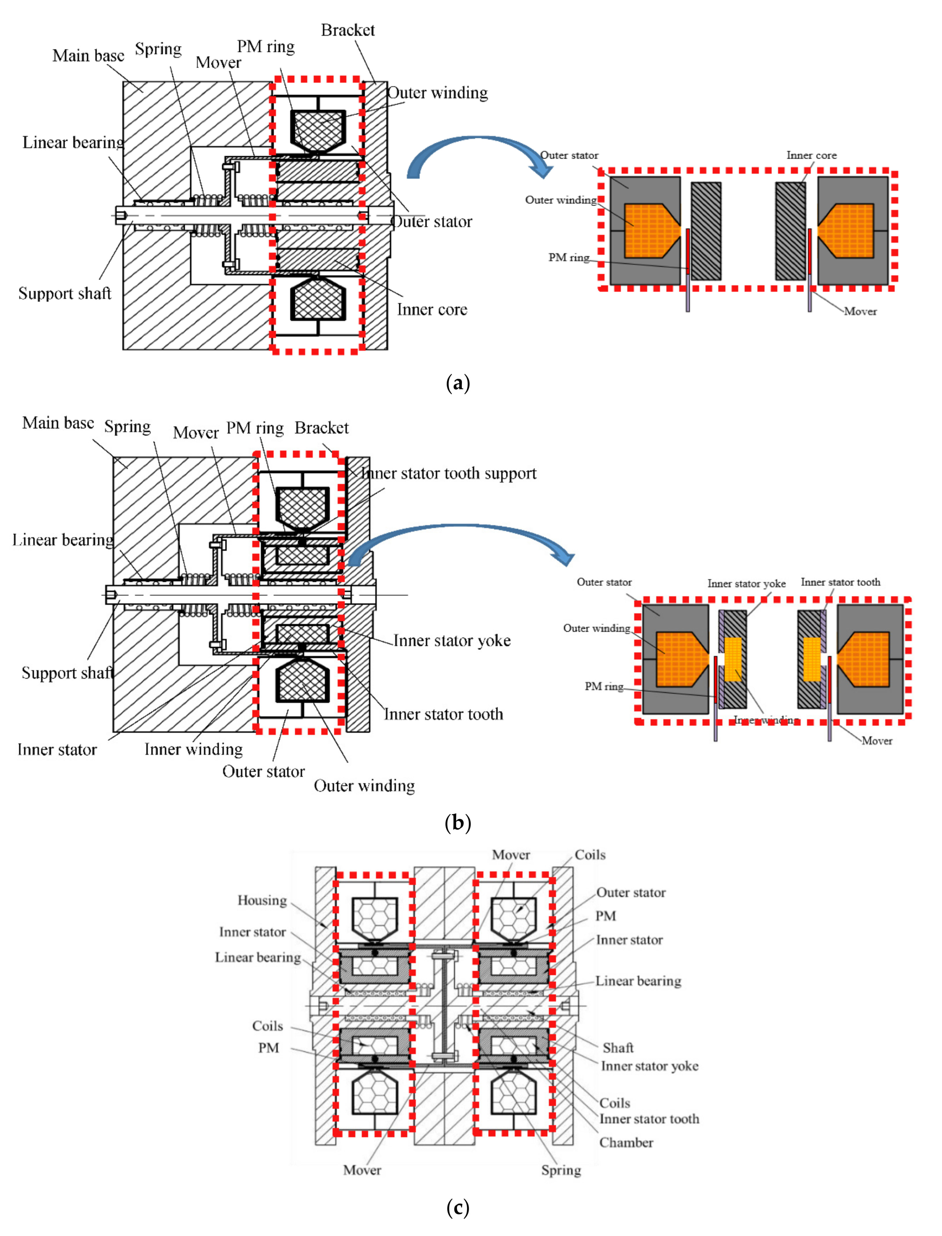
2.1. Motor Topologies and Operating Principles
2.2. Design Principle of the PM Linear Motors
3. Characteristics Analysis and Comparison
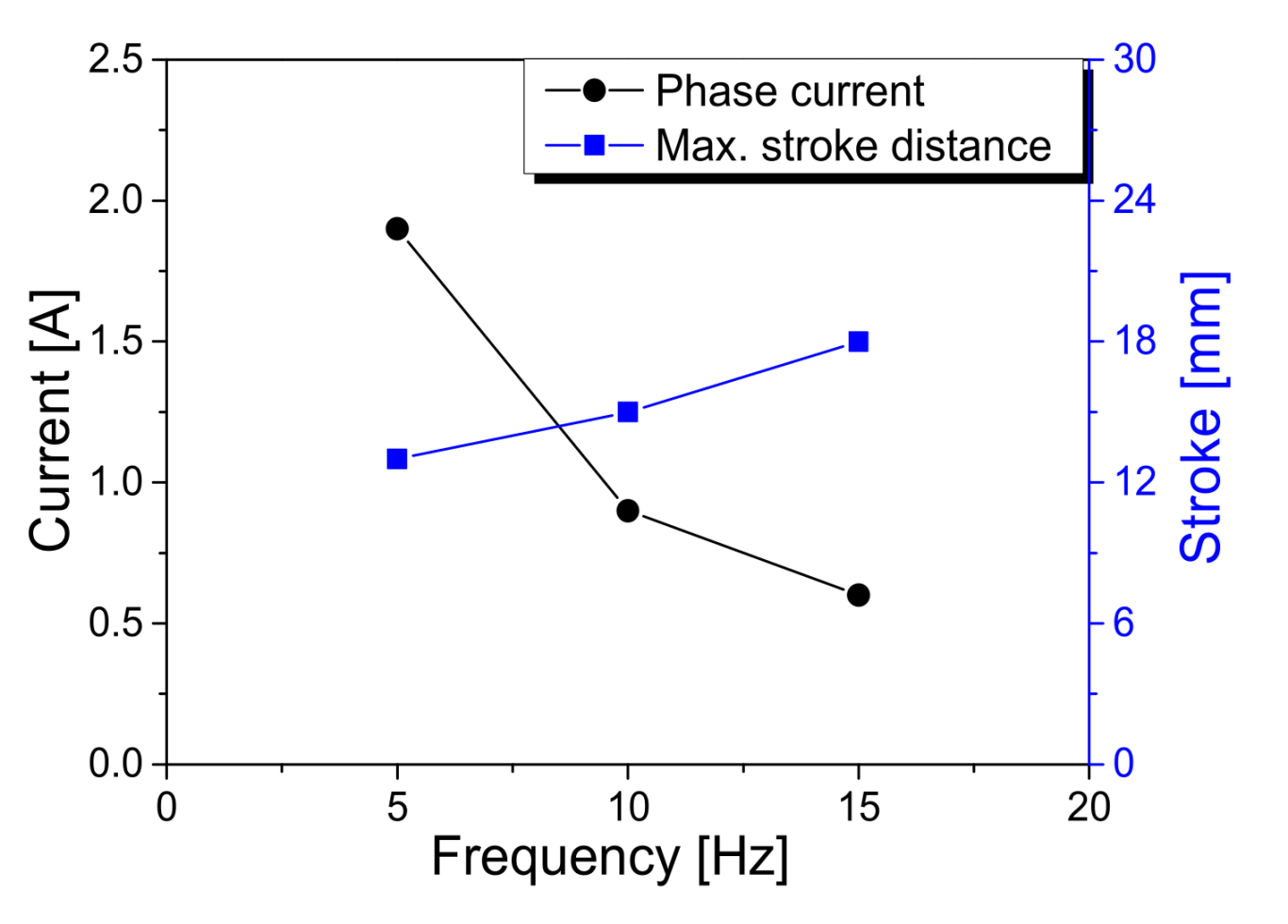
4. Prototype and Experimental Discussion
5. Conclusions
Author Contributions
Funding
Institutional Review Board Statement
Informed Consent Statement
Data Availability Statement
Acknowledgments
Conflicts of Interest
References
- Utsuno, M.; Takai, M.; Yaegashi, T.; Mizuno, T.; Yamamoto, H.; Shibuya, K.; Yamada, H. Efficiency characteristics of a linear oscillatory actuator under simulated compressor load. In Proceedings of the 2001 Linear Drives and Industry Applications (LDIA’2001), Nagano, Japan, 17–19 October 2001; pp. 264–267. [Google Scholar]
- Chun, T.; Ahn, J.; Yoo, J.; Lee, C. Analysis and control for linear compressor system driven by PWM inverter. In Proceedings of the 30th Annual Conference of the IEEE Industrial Electronics Society, Busan, Korea, 2–6 November 2004; pp. 263–267. [Google Scholar]
- Wang, J.; Howe, D.; Lin, Z. Comparative studies on linear motor topologies for reciprocating vapour compressors. In Proceedings of the International Electrical Machines and Drives Conference (IEMDC2007), Antalya, Turkey, 3–5 May 2007; pp. 364–369. [Google Scholar]
- Lee, H.; Song, G.; Park, J.; Hong, E.; Jung, W.; Park, K. Development of the linear compressor for a household refrigerator. In Proceedings of the International Compressor Engineering Conference, West Lafayette, IN, USA, 25–28 July 2000; Purdue e-Pubs: West Lafayette, IN, USA, 2000. [Google Scholar]
- Chen, X.; Jiang, H.; Li, Z.; Liang, K. Modelling and measurement of a moving magnet linear motor for linear compressor. Energies 2020, 13, 4030. [Google Scholar] [CrossRef]
- Xia, Y.; Lu, Q.; Ye, Y.; Kang, R. Analysis and modeling of a new type of dual-stator linear oscillation motor. Trans. Chin. Soc. Electr. Eng. 2007, 12, 29–33. [Google Scholar]
- Hur, K.; Lee, H. Linear Compressor. U.S. Patent 6398523B1, 4 June 2002. [Google Scholar]
- Ibrahim, T.; Wang, J.; Howe, D. Analysis and experimental verification of a single-phase, quasi-halbach magnetized tubular permanent magnet motor with non-ferromagnetic support tube. IEEE Trans. Magn. 2008, 44, 4361–4364. [Google Scholar] [CrossRef]
- Wang, J.; Howe, D.; Lin, Z. Design optimization of short-stroke single-phase tubular permanent-magnet motor for refrigeration applications. IEEE Trans. Ind. Electron. 2010, 57, 327–334. [Google Scholar] [CrossRef]
- Kwon, Y.; Kim, W. Detent-force minimization of double-sided interior permanent-magnet flat linear brushless motor. IEEE Trans. Magn. 2016, 52, 8201609. [Google Scholar] [CrossRef]
- Kim, T.; Lee, H.; Kim, Y.; Lee, J.; Boldea, I. Development of a flux concentration-type linear oscillatory actuator. IEEE Trans. Magn. 2004, 40, 2092–2094. [Google Scholar] [CrossRef]
- Clark, R.; Jewell, G.; Howe, D. Dynamic modeling of tubular moving-magnet linear actuators. J. Appl. Phys. 2003, 93, 8787–8789. [Google Scholar] [CrossRef]
- Xu, J.; Zhao, W.; Wang, X.; Wang, X.; Wang, F. Design and analysis of a novel dual-stator tubular linear machine with split teeth structure. In Proceedings of the 13th International Symposium on Linear Drives for Industry Applications (LDIA), Wuhan, China, 1–3 July 2021; pp. 1–5. [Google Scholar]


| Items | Unit | Model 1 | Model 2 | Model 3 |
|---|---|---|---|---|
| Current density Jc | A/mm2 | 6~8 | 6~8 | 6~8 |
| Overall outer radius Ro | mm | 82 | 82 | 82 |
| Inner stator outer radius Rio | mm | 32 | 32 | 32 |
| Inner stator inner radius Rii | mm | 23.5 | 18 | 18 |
| Motor axial length l | mm | 52 | 52 | 104 |
| Outer airgap length go | mm | 1 | 1 | 1 |
| Inner airgap length gi | mm | 0.8 | 0.8 | 0.8 |
| Outer coil no. of turns No | -- | 800 | 800 | 800 |
| Inner coil no. of turns Ni | -- | 0 | 150 | 150 |
| PM thickness gm | mm | 3 | 3 | 3 |
| PM height lpm | mm | 25 | 25 | 50 |
| Magnet (NdFeB) | -- | Br = 1.23 T, Hc = −890 kA/m | ||
| Items | Unit | Model 1 | Model 2 | Percentage Change |
|---|---|---|---|---|
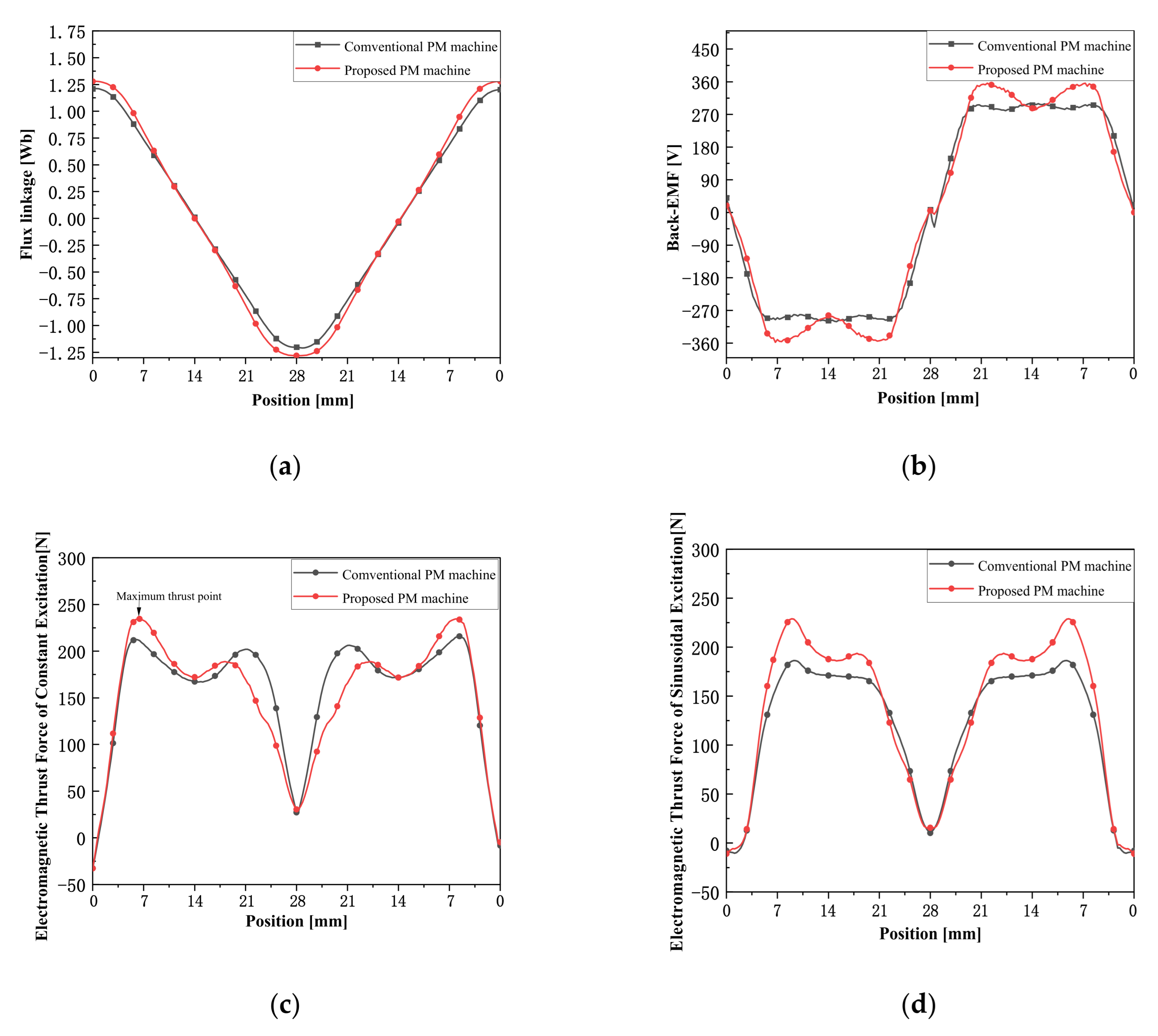
| Maximum flux linkage | Wb | 1.21 | 1.28 | +5.78% |
| Maximum back-EMF | V | 299.84 | 350.08 | +16.76% |
| Maximum thrust force | N | 215.95 | 249.23 | +15.41% |
| Output power P | W | 468.33 | 497.06 | +6.13% |
| Copper loss Pcu | W | 70.05 | 76.15 | +8.72% |
| Motor efficiency η | -- | 85.81% | 86.57% | +0.77% |
| Items | Unit | Designed Model 2 | Prototype of Model 2 | Prototype of Model 3 |
|---|---|---|---|---|
| Max. stroke distance d | mm | 22 | >18 | >20 |
| Mover mass m | kg | 0.42 | 0.55 | 1.41 |
| Max. air pressure in air cylinder P | kg | >16 | 20 | 42 |
Publisher’s Note: MDPI stays neutral with regard to jurisdictional claims in published maps and institutional affiliations. |
© 2021 by the authors. Licensee MDPI, Basel, Switzerland. This article is an open access article distributed under the terms and conditions of the Creative Commons Attribution (CC BY) license (https://creativecommons.org/licenses/by/4.0/).
Share and Cite
Zhao, F.; Jiang, Y.; Yang, K.; Zhang, C.; Lian, W.; Wang, G. Comparison Study on High Force Density Linear Motors for Compressor Application. Energies 2021, 14, 7417. https://doi.org/10.3390/en14217417
Zhao F, Jiang Y, Yang K, Zhang C, Lian W, Wang G. Comparison Study on High Force Density Linear Motors for Compressor Application. Energies. 2021; 14(21):7417. https://doi.org/10.3390/en14217417
Chicago/Turabian StyleZhao, Fei, Yunshuai Jiang, Kuang Yang, Chengming Zhang, Wei Lian, and Guangyin Wang. 2021. "Comparison Study on High Force Density Linear Motors for Compressor Application" Energies 14, no. 21: 7417. https://doi.org/10.3390/en14217417
APA StyleZhao, F., Jiang, Y., Yang, K., Zhang, C., Lian, W., & Wang, G. (2021). Comparison Study on High Force Density Linear Motors for Compressor Application. Energies, 14(21), 7417. https://doi.org/10.3390/en14217417