Article

On the Quality of Street Lighting in Pedestrian Crossings

by
Malgorzata Zalesinska
* and
Krzysztof Wandachowicz
Division of Metrology, Electronics and Lighting Engineering, Poznan University of Technology, 60-965 Poznan, Poland
*
Author to whom correspondence should be addressed.
Energies 2021, 14(21), 7349; https://doi.org/10.3390/en14217349
Submission received: 30 September 2021 / Revised: 20 October 2021 / Accepted: 30 October 2021 / Published: 4 November 2021

Abstract

:
The pedestrian is the least protected road user. A large number of accidents involving pedestrians occur at pedestrian crossings. Bad lighting or a complete lack of it is one of the causes of accidents in these places. Currently, there are no uniform requirements in Europe for the lighting of pedestrian crossings. Each country is trying to create its system of requirements and assessment of lighting of pedestrian crossings. Measurement procedures and required lighting parameter values often vary significantly across countries. This paper discusses the results of measurements carried out at selected pedestrian crossings using two different measurement grids. The lighting quality at the tested crossings has been assessed based on the lighting requirements in force in two EU countries. In addition, we present the results for the illuminance contrast of a measurement board, representing the silhouette of a pedestrian on a crossing, with the background. Based on the determined contrast, we attempted to verify the lighting conditions using an evaluation system described in the literature, which employs fuzzy logic algorithms.

1. Introduction

Annually, more than 22,000 people die and over 1 million are injured on European roads. Of all fatalities, about 21% are pedestrians. However, these statistics vary considerably across EU countries. For many years, Poland has counted among the countries with the highest number of road accidents per 1 million inhabitants, including those involving pedestrians [1,2]. In 2020, more than 5200 accidents involving pedestrians were recorded in Poland (22.2% of the total), with 631 deaths (25.3% of the total) and almost 4700 injuries (17.8% of the total) [3]. The risk of a pedestrian losing his or her life at a pedestrian crossing in Poland is more than twice as high as in the Czech Republic, more than seven times higher than in Sweden, and more than 20 times higher than in Germany. Moreover, statistics show that in Poland, a pedestrian crossing is the second most dangerous place of road infrastructure, just after a roadway [3].
Pedestrian safety in collision zones depends on many factors. The most important of these include the type of pedestrian crossing, e.g., zebra crossing with or without traffic lights, the type of road and length of the crossing, the volume of vehicles and pedestrian traffic, vehicle speed, and pedestrian and vehicle visibility, particularly at night. While during the day a pedestrian’s visibility is determined by factors other than lighting, at night proper zebra crossing lighting can reduce the number of accidents involving pedestrians by about 20–30% [4].
The best lighting conditions at pedestrian crossings, and thus improved pedestrian visibility, can be achieved by additionally illuminating the crossing with a luminaire with asymmetrical light distribution. This solution allows for high values of the vertical illuminance value and a positive luminance contrast between the pedestrian and the background (Figure 1). When using stationary road lighting to illuminate a pedestrian crossing it is practically only possible to achieve negative contrast. If the road on which the pedestrian crossing is located has a high luminance level, it is possible to achieve a “good” negative contrast (Figure 2), otherwise, the negative contrast may be insufficient to make the pedestrian’s silhouette visible (Figure 3).
In order to verify the quality of illumination of selected pedestrian crossings, measurements were carried out, and the results of the measurements and their analysis are described in this paper. The following work structure has been adopted. A review of the literature and lighting requirements for pedestrian crossings has been carried out. The research objects are described. The applied measurement procedure in relation to the measurement of illuminance is described. The results of the measurements of lighting quality and the analysis of the results are presented. The procedure adopted for the measurement of luminance contrast at the tested pedestrian crossings is described. Test results and their analysis are given. Conclusions have been formulated.

2. Lighting Requirements at Pedestrian Crossings

Ensuring road safety, especially for pedestrians in zones of conflict with motor vehicles, should be a priority for every country. Research is being carried out all over the world to determine the lighting requirements ensuring good pedestrian visibility. A sufficiently high luminance level, especially in the vertical plane, is necessary to make a pedestrian clearly visible. Studies by Freedman et al. [5] and Hasson et al. [6] pointed to vertical illuminance values of 40 lx. Research by Gibbons and Hankley [7], showed that 20 lx was already sufficient to spot objects at pedestrian crossings. In a later study, Edwards and Gibbons [8] analyzed the effect of lamp spectral distributions on pedestrian visibility. They performed field tests using a passenger car and, based on an analysis of object detection distances, showed that 20 lx with metal-halide lamps and 30 lx with high-pressure sodium lamps provided sufficient illuminance levels for spotting objects. The effect of spectral distribution on pedestrian visibility was also studied by Pena-Garcia et al. [9], Markvica et al. [10], Davidovic et al. [11], and Pastella et al. [12]. Based on their research, the authors found a positive effect of LED lamps on pedestrian visibility. Pedestrian safety analysis also includes assessing the quality of pedestrian crossing lighting and the achievable illuminance levels [13]. The literature also contains studies of luminance contrasts at pedestrian crossings [14,15,16,17]. Other research on pedestrian crossing lighting focused on energy savings and environmental implications associated with LED luminaires [18,19,20]. Moreover, research is also conducted to optimize lighting design criteria including pedestrian crossings for energy efficiency, environmental sustainability, and driver as well as citizen comfort [21,22].
There are numerous projects carried out in the European Union, both at the central level and in individual countries of the community, to improve road traffic safety, including the safety of pedestrians in collision zones with other road users. In February 2021, the Safe Road Infrastructure Program 2021–2024 was passed in Poland [23]. Several tasks will be implemented under this program, such as the reconstruction of roads, expansion of infrastructure with new pavements, left turns or pedestrian bridges. Priority has been given to the safety of vulnerable road users. Pedestrian crossings and bicycle crossings should be adequately illuminated first. Research conducted for several years at the Poznan University of Technology shows the scale of the problem we are faced with. Among 20 crossings, tested only in 2020 and 2021, values of the vertical illuminance in the crossing zone ranged from about 1 lx to several dozen lx. Nevertheless, to assess whether a dozen or a few dozen lux is sufficient to ensure good pedestrian visibility it is necessary to refer to lighting requirements.
Currently, there are no uniform requirements in Europe for the lighting of pedestrian crossings. The EN 13201 “Road lighting” [24] standard includes only general guidelines for the lighting of pedestrian crossings. It does not specify any quantitative requirements. Appendix to part 2 of the standard only provides general guidelines stating that if the illuminance level of the roadway is sufficiently high, a sufficiently high negative contrast can be achieved with the correct positioning of the stationary road lighting luminaires, and if additional luminaires are provided to illuminate the crossing, they should directly illuminate the pedestrian’s silhouette at the crossing and at the same time draw drivers’ attention to the existence of the crossing. It is also recommended that the illuminance measured in the vertical plane be significantly higher than in the horizontal roadway plane and that the waiting zones at the ends of the crossing be properly illuminated as well.
In the absence of quantitative requirements at the European level, each country is attempting to develop its system of requirements and assessment for correct illumination of pedestrian crossings. Analyzing the standards applicable in individual countries in Europe, differences in the levels of lighting parameters required or the location of measurement points are observed. Below, we describe examples of lighting requirements applicable in Germany, the Czech Republic and Poland.
In Germany, the DIN 67523 “Lighting of pedestrian crossings with supplementary lighting” standard [25] has been in force for many years and is a supplement to EN 13 201 [24]. The German standard emphasizes the need for the contrast between the pedestrian silhouette and the background. This contrast can be achieved by using luminaires with asymmetrical light distribution located in front of the crossing, from each direction of travel, and thus ensuring a sufficiently high vertical illuminance value. Both the pedestrian crossing itself and the waiting area must be illuminated. The only case where there is no need for additional crossing lighting is when the road meets class M2 (lighting class for motorized traffic) lighting requirements. The quality of pedestrian crossing lighting should be assessed at measurement points distributed along a line passing through the center of the crossing and located at a height of 1 m in the direction of oncoming traffic. The average vertical illuminance at these points shall be at least 30 lx. In addition, the vertical illuminance at each point shall be at least 4 lx, excluding the waiting area. The layout of the measurement grid is shown in Figure 4.
Due to the adaptation of the driver’s eyesight to the lighting conditions at a distance between 100 m and 50 m, both before and after the pedestrian crossing, it is recommended to use class M6 lights, and the area of 50 m in front of and behind the pedestrian crossing should be illuminated under the lighting requirements provided for class M2.
In the Czech Republic, lighting requirements for pedestrian crossings are included in the document on technical conditions for road construction [26].
Czech regulations requirements and location of measuring points differ significantly from the German requirements. The required average illuminance levels at crossings depend on the road illuminance levels. Minimum and maximum requirements are defined for the vertical illuminance of the roadway and waiting area illuminance. The measurement points should be 1 m above the road surface and should be positioned as per the measurement grid shown in Figure 5. Table 1 summarizes the lighting requirements.
In addition, the overall uniformity (U0V [-]) shall be at least 0.4 and the ratio of vertical illuminance at the pedestrian crossing to vertical illuminance in the waiting area shall be between 0.5 and 2.
What is unique at the European scale is that the length of the transition zone before and after the pedestrian crossing depends on the maximum speed allowable on the street in question. The length of the transition zone ranges from 50 m for speeds of 30 km/h to 150 m for permitted speeds greater than 50 km/h.
In Poland, in 2018, the Minister of Infrastructure published use guidelines in a study entitled “Guidelines for the organization of safe pedestrian traffic-guidelines for correct lighting of pedestrian crossings” [13]. This publication contains a description of the measurement procedure as well as lighting requirements for a pedestrian crossing. The authors do not provide any test results being the basis for the adopted requirements. However, when reading the entries included in this study, we can notice a very strong convergence in measurement methodology with the German requirements, and with the Czech requirements concerning the assessment of lighting values. Similar to the Czech requirements, illumination levels at pedestrian crossings were made dependent on the street illumination level. For motorized traffic (lighting classes M) the distance used for determining the road illumination levels is 100 m, and for conflict areas (lighting class C) it is 50 m. In addition to the vertical illuminance, there are also requirements for the horizontal component at the crossing plane and minimum values for the vertical illuminance at certain points in crossing peripheral areas. There are no requirements for maximum values of the vertical illuminance. The measurement points are located only along the central pedestrian crossing line, similar to the German requirements, but the measurements need to be taken at three heights: 0.5 m, 1 m, 1.5 m.
Figure 6 and Figure 7 show the appearance of measurement grids for determining the vertical and horizontal of illuminance at a pedestrian crossing.
Table 2 summarizes the Polish lighting requirements for pedestrian crossings as recommended by the Ministry of Infrastructure.
In addition, the overall uniformity of the vertical illuminance (U0V [-]) shall be at least 0.35 and overall uniformity of the horizontal illuminance (U0h [-]) −0.4.
In addition, the Polish recommendations also provide for the necessity of making requirements at a given crossing more stringent if there is an increased risk of road accidents, the possibility of glaring the driver or if conditions for observing the pedestrian crossing are difficult.

3. Aim and Scope of the Study

Based on the review of lighting standards, a high similarity was observed between Polish and Czech lighting requirements even if different measurement grids were used. When reviewing the literature, we found descriptions of measurements of the lighting quality of pedestrian crossings [13,14,15,16,17,18,19,20], but in no case was a comparison made between different measurement procedures for the same crossing. Only one measurement procedure was used. The procedure for measuring lighting quality was not evaluated critically. Therefore, we decided to evaluate the possibility of using different measurement procedures to assess the lighting quality on the same crossing. For this purpose, we performed illumination quality tests at selected pedestrian crossings according to Polish and Czech measurement procedures (Figure 4, Figure 5 and Figure 6). Lighting quality was assessed according to the requirements for the relevant procedure (Table 1 and Table 2). We analyzed the results obtained and assessed whether it makes sense to use such a combination to assess the quality of lighting at pedestrian crossings.
Since pedestrian visibility at crossings is also determined by the contrast between the pedestrian’s silhouette and the background, we also decided to investigate the luminance contrast at selected pedestrian crossings. For this purpose, an array sized 1 m × 0.5 m with the same reflectance (ρ) as for the CIE standard obstacle ρ = 0.2 [28] was prepared (Figure 8).
Three pedestrian crossings on roads with stationary lighting were selected for the study. One crossing had no additional illumination of the crossing area. The other two were additionally illuminated using luminaires with asymmetrical light distribution, placed in front of the pedestrian crossing for each traffic direction.
The night look of the tested pedestrian crossings together with basic dimensions are presented in Figure 9, Figure 10 and Figure 11.
The first analyzed pedestrian crossing was located on a local, one-way road with trees growing close to the street. The crossing was located close to a stationary road lighting luminaire.
The second pedestrian crossing was located on a two-way road, passing through residential areas, with a green belt separating the housing estate from the street. One of the luminaires illuminating the pedestrian crossing was located on a shared pole intended for stationary lighting luminaires.
The third pedestrian crossing was located on the two-way road approaching a roundabout. Next to the pedestrian crossing was a bike path, which was also the subject of the study. On the road in question, there was a pedestrian and cyclist refuge at the crossing and the bike path.
All the analyzed pedestrian crossings were located on streets with a traffic speed limit of 50 km/h.
The basic dimensions are presented in Appendix A, Figure A1, Figure A2 and Figure A3.

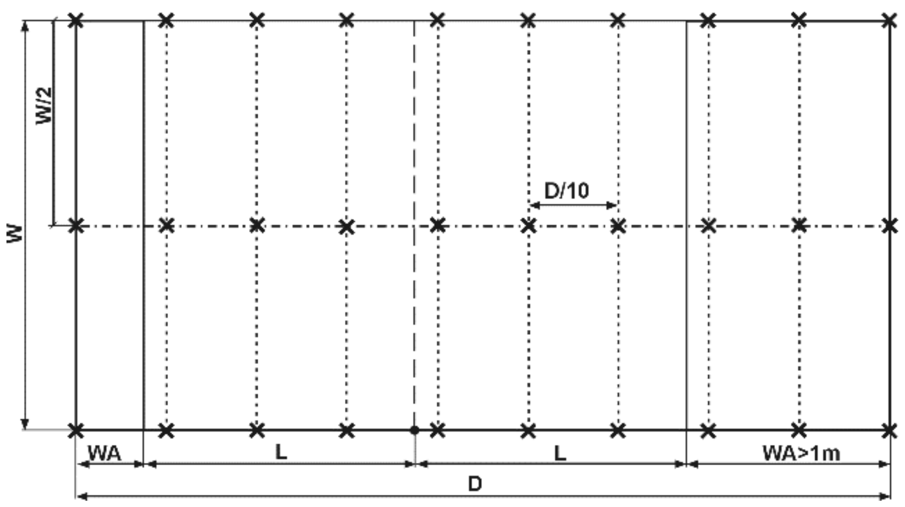
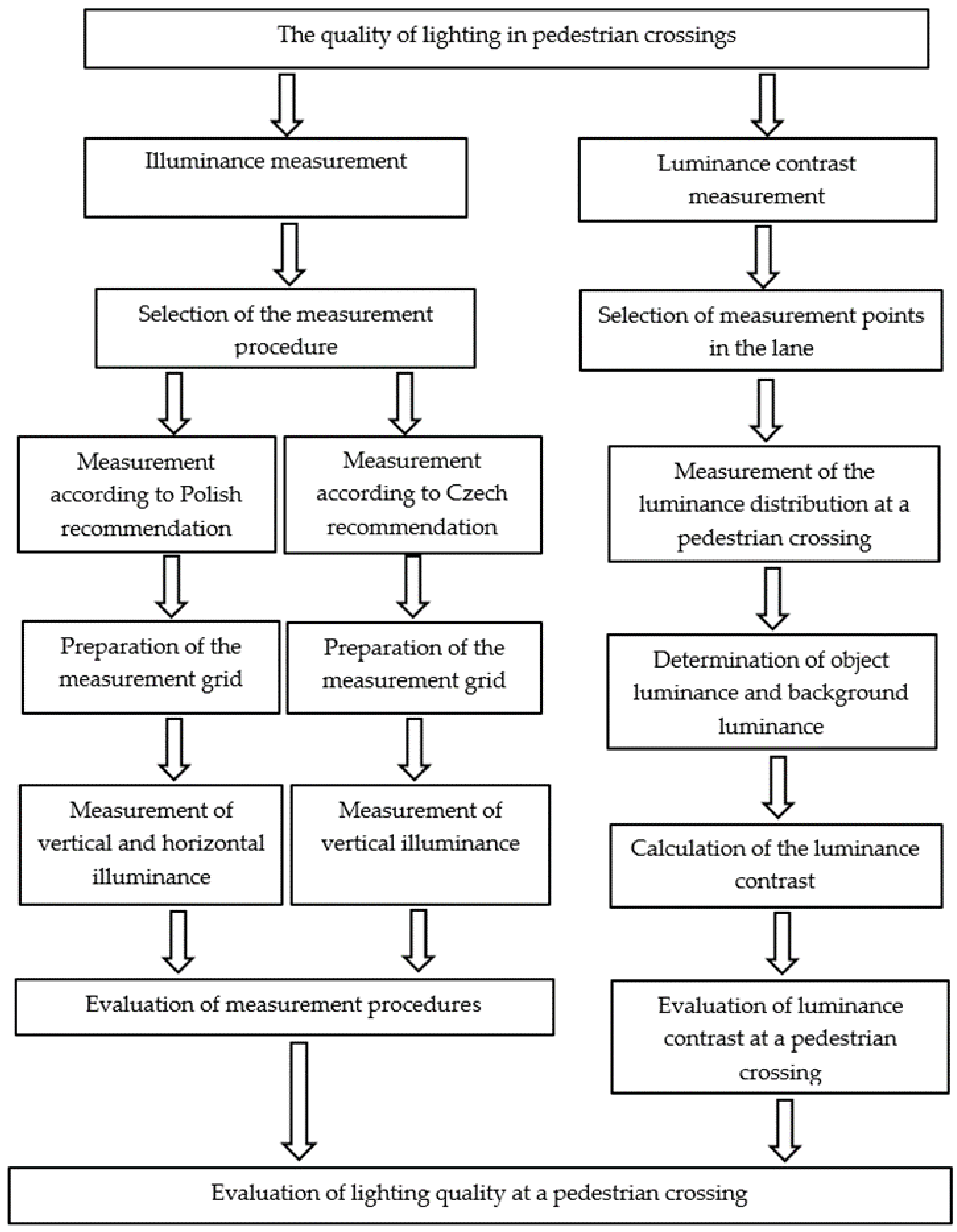
4. Materials and Method

The quality of lighting of pedestrian crossings was assessed following the requirements applicable in the Czech Republic and Poland. No significant difference was found between these requirements in terms of the numerical values of vertical illuminance (see Table 1 and Table 2). However, there are significant differences in the measurement procedures in both countries (see Section 2). Two measurement grids were prepared for each pedestrian crossing. The first grid accounts for the Polish requirements. According to these requirements, the waiting zone was considered part of the pedestrian crossing. For pedestrian crossings no. 1 and 2, the waiting zone covered 1 m on the pavement on each side. For crossing no. 3, the one-meter waiting zone only applied to the pavement, whereas there was a 2.8 m waiting zone on the pedestrian refuge (see Appendix A, Figure A3). The vertical illuminance (Ev in [lx]) was measured at 10 measurement points evenly distributed along a line passing through the center of the pedestrian crossing (see Figure 6). The minimum vertical illuminance value was measured at six points along the crossing’s contour-the boundary points (see Figure 6). Vertical illuminance (Eh (in [lx]) was measured at 30 points according to the grid shown in Figure 7.
Lighting quality according to the Czech recommendations was measured according to the measurement grid shown in Figure 5. Separate points were defined for the zebra crossing and the waiting zone. On the carriageway, in line with the grid used for street lighting, nine measurement points were defined for each lane. The dimensions of the waiting zones were the same as those used in the measurement procedure according to the Polish method. For the pavement (one-meter waiting zone) there were three measurement points and for the refuge, there were nine points.
To determine the lighting requirements to be met at a given pedestrian crossing, luminance measurements were carried out over a distance of 100 m before the crossing (L in cd/m2), with the observer’s position maintained in accordance with the requirements of the EN 13201 standard [24].
Due to the use of pedestrian refuge islands at crossing no. 3, which is a zone intended for the pedestrian to wait at before entering the roadway, for the measurements and analysis of the results each roadway was treated as a one-way road.
Board luminance and the board background luminance measurements were performed for the standard observer position used in road luminance measurements [24], except for the direction in which vehicles exit the roundabout at crossing no. 3. In this case, measurements were taken from a closer distance while maintaining the same angle of street observation.
For the test objects, the luminance of the board and its background was measured at three points along the lane, on the line running through the center of the crossing. The surface directly adjacent to the board on the right and the left, with the same dimensions as the board, was taken as the background of the pedestrian silhouette.
Figure 12 shows the areas considered for the luminance contrast measurements.
Figure 13 schematically presents the measurement procedure used during the tests.

5. Estimation of Measurement Uncertainty

The illuminance measurements were performed with a class A illuminance meter consistent with the CIE classification [29]. The general V(λ) (spectra luminous efficiency for photopic vision) mismatch index f1′ of the illuminance meter head proven with a calibration certificate was 2% and the overall uncertainty was 2.5%. In addition, the measurement uncertainty associated with the directional mismatch of the illuminance meter head (index f2) of 1.5% should be taken into account. The total measurement uncertainty was also affected by the positioning of the meter. With the measurement method used, the vertical positioning of the meter could achieve an accuracy of 10 degrees so that the uncertainty associated with the positioning of the lux meter was estimated at 1.5%. Therefore, we think that the total uncertainty of the illuminance measurement did not exceed 5.5 %. For the luminance measurement, the general V(λ) mismatch index f1′ was 4% and the total meter uncertainty was 10%. Since the board used had a nearly Lambertian reflectance, we believe that the total uncertainty of the luminance measurement did not exceed 10%.

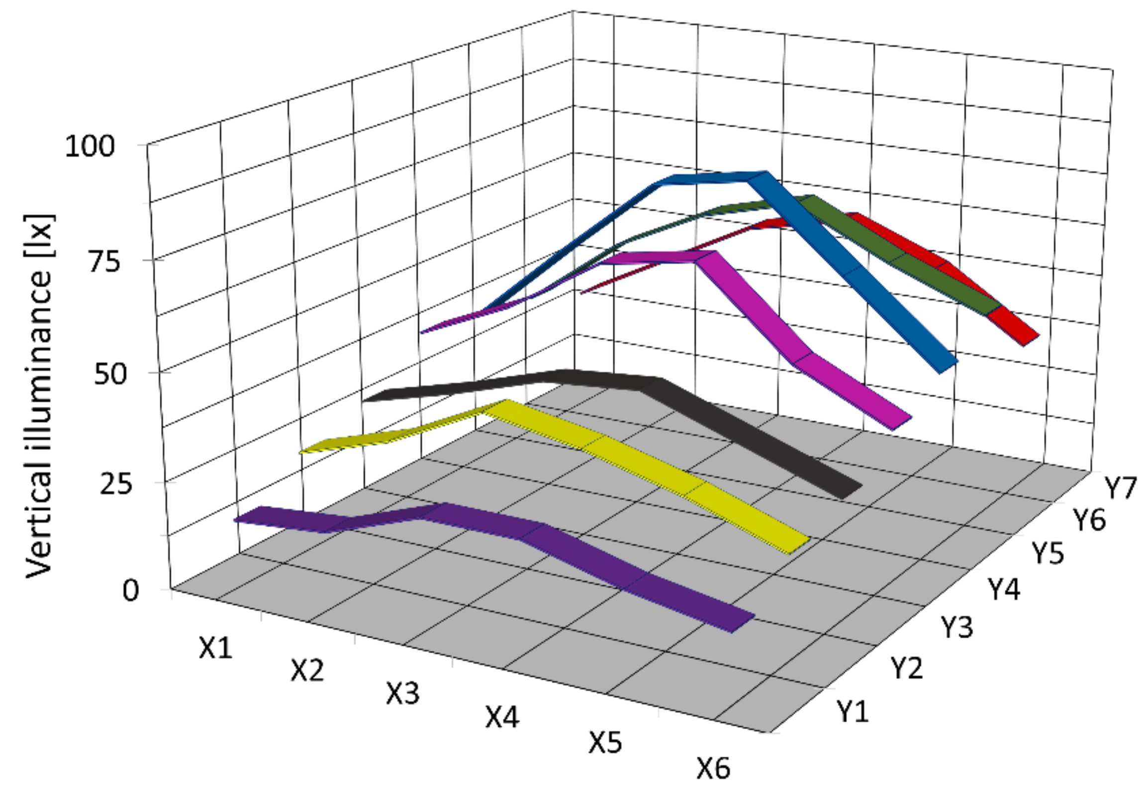
6. Measurements of Illuminance at the Analyzed Pedestrian Crossings

The average values of the vertical and horizontal illuminance were calculated based on the measurement results and are presented in Table 3 and Table 4.
The measurement results at the tested pedestrian crossings are presented in Appendix B, Table A1, Table A2, Table A3, Table A4 and Table A5.
An example of the luminance distribution in front of a pedestrian crossing is shown in Figure 14.

7. Evaluation of Illumination Quality and Measurement Procedures at the Pedestrian Crossings under Analysis

7.1. Evaluation of Lighting Parameters at the Pedestrian Crossings

Our tests of the quality of lighting at zebra crossings as per the Czech guidelines and the Polish recommendation have shown that it is necessary to add some additional lights at crossing no. 1. Regardless of the measurement method and adopted assessment criterion, crossing no. 1 failed to meet any requirements, even though the stationary road lighting luminaire was located near the crossing and the crossing itself was only 4.3 m long (without the waiting zone). Analyzing the measurement results obtained with the two different measurement grids, we can conclude that similar values were obtained for the vertical illuminance. Significant differences were obtained for the uniformity of the vertical component. This results from the assumptions made in both methods. In the Czech method, the pedestrian crossing is understood as the area consisting of the “zebra” without a waiting zone. In the Polish method, the pedestrian crossing is assessed together with the waiting zone. Thus, at low illuminance levels in one zone (in this case on the right side of the crossing—see Figure 9), large differences in uniformity can be observed.
For crossing no. 2, regardless of the adopted assessment criterion for the quality of crossing illumination, no need for additional illumination was revealed, because with the roadway luminance levels 100 m before the crossing for both directions of traffic being 3.63 cd/m2 and 2.90 cd/m2, respectively, and with such high luminance levels, the pedestrian silhouette was found to create sufficiently high positive contrast to ensure good visibility. Nevertheless, additional lighting was used at this crossing, which fully meets the most stringent lighting requirements for pedestrian crossings, both Czech and Polish.
Pedestrian crossing no. 3, similarly to crossing no. 2, had additional lighting. However, this crossing differs in its design from the other two objects of our analysis. There is a bike path next to the pedestrian crossing itself and both roadways are separated by a pedestrian refuge island. In each of the analyzed cases, the refuge was treated as a waiting zone and the roadway as one-way roads. Both for the C direction (traffic towards the roundabout) and the D direction (traffic away from the roundabout) the lighting requirements according to Polish criteria were met. According to the Czech requirements for assessing crossing and bike path illumination, although the required minimum illuminance on the roadway and waiting zones were met, the differences between the values were too high.

7.2. Evaluation of the Measurement Procedures

In addition to checking the quality of illumination at the crossing itself, the measurements performed for selected pedestrian crossings were also intended to assess the possibility of using different measurement procedures with very similar lighting requirements in terms of the vertical illuminance in the conflict zone. Analyzing the results obtained from the study and based on our previous experience [30], we concluded that for pedestrian crossings without additional illumination, there are no significant differences in the determined values of the vertical illuminance. Most often, stationary roadway lighting is used to obtain adequate parameters on the roadway surface rather than in vertical planes. However, differences are observed for uniformity. Usually, in the absence of additional lighting, at least one waiting zone exhibits much lower values than the remaining area.
If a pedestrian crossing has additional lighting and relatively small width, the differences in the determined values of the vertical illuminance, using different measurement grids, are much greater (see crossing no. 2). If the measurement grid recommended in Poland is used and measurements are performed only along the center line of the crossing, higher values of the vertical illuminance are obtained, but it does not mean that the whole area is illuminated better. The vertical illuminance is not subject to verification outside the central line. With such an approach, for wide pedestrian crossings, there may be places outside the central line where the pedestrian’s silhouette is not sufficiently illuminated. The recommendation indeed provides for minimum values of the vertical illuminance at points located on the periphery of the crossing, but these values are many times lower than at the pedestrian crossing itself (from 2 lx to 5 lx-see Table 2). For the Czech requirements, the average vertical illuminance value is determined based on measurements for three lines running along the crossing. This results in lower values, but a better reflection of the illumination conditions of the whole crossing. We think that this approach is more appropriate to ensure good pedestrian visibility across the entire pedestrian crossing.
Figure 15 shows the distribution of illuminance at the pedestrian crossing determined in line with the Czech method, which shows the differences between the values in the central line and the side lines.
Analysis of the results of the measurements carried out for pedestrian crossing no 3 and the bike path also revealed the influence of the measurement grid on the measured values. Because the tests were performed separately for the pedestrian crossing and the bike path, lower values were obtained if the Polish measurement procedure was applied. The vertical illuminance was lower due to the measurement points being located outside the area towards which the maximum luminous intensity of the asymmetrical light luminaire illuminating the conflict zone was directed.
Although no measurements were taken for the line in the middle of the whole illuminated area, from the analysis of illuminance distribution obtained with the Czech measurement grid in each area we can see that the maximum values of the vertical illuminance are located at the border of the bike path and the pedestrian crossing (between lines X3 and X4 see Figure 16).
The field measurements conducted have also shown that it is not necessary to take measurements, as provided for in the Polish guidelines, at 3 heights of 1.5 m, 1.0 m, and 0.5 m. The differences between the average value obtained from measurements made at all 3 heights and the measurements taken at 1 m did not exceed 1% and significantly increased analysis time.

8. Measurements and Assessment of Luminance Contrast at the Analyzed Pedestrian Crossings

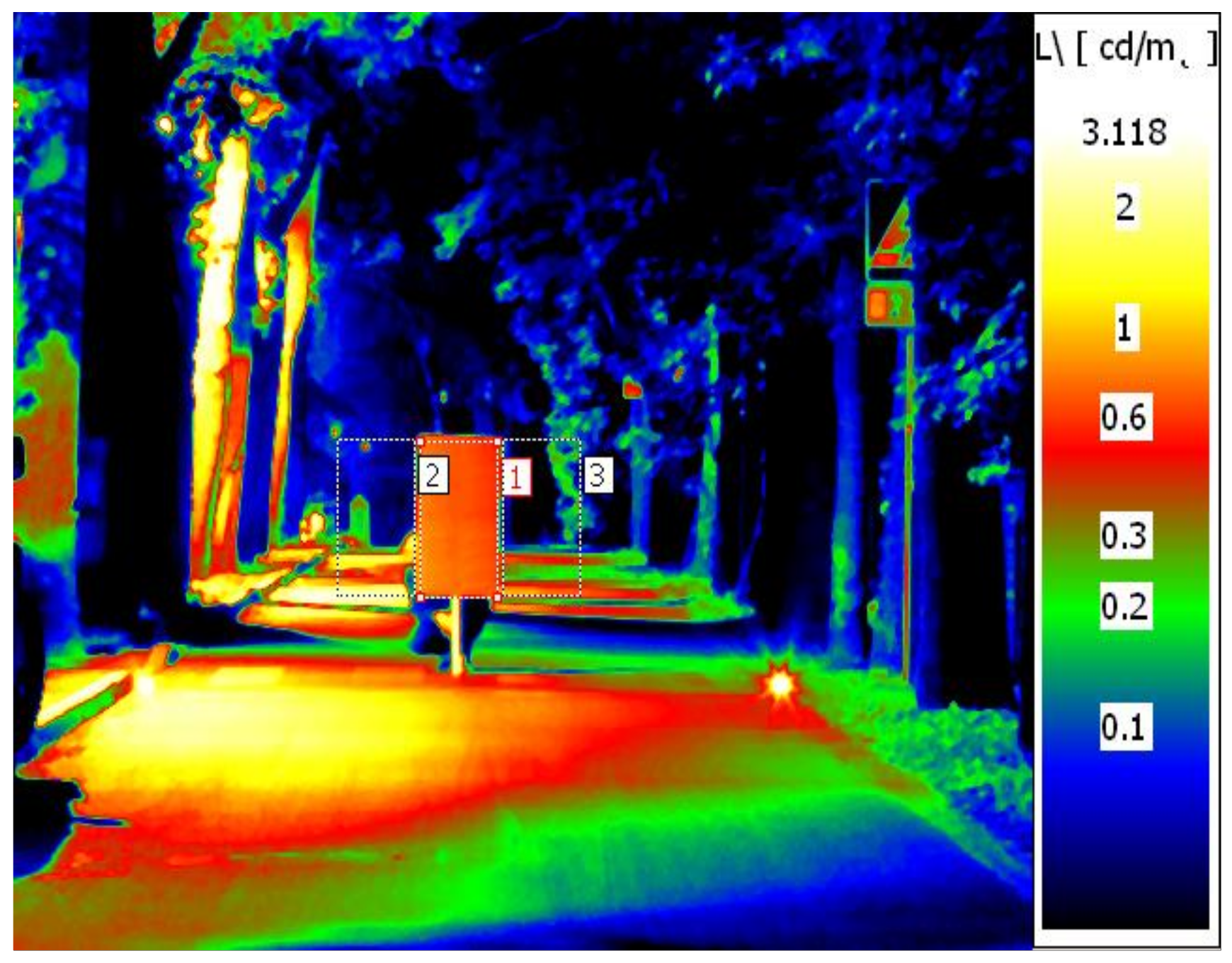
8.1. Measurements of Luminance Contrast

The results of luminance contrast measurements and calculations are summarized below.
Figure 17, Figure 18 and Figure 19 show an example of luminance distribution on the board and in its background area for each of the tested pedestrian crossings. Since in real life the pedestrian moves across the pedestrian crossing, average background luminance and contrasts values have been used to assess the visibility of the pedestrian silhouette.
Table 5 summarizes the results of measurements and calculations.
Detailed the results of measurements and calculations are shown in Appendix B, Table A6.

8.2. Assessment of the Results Obtained

Luminance contrast is a parameter that depends on the luminance of both the object and its background. As expected, the pedestrian crossings for which high values of the vertical illuminance were obtained also exhibited high measurement board luminance levels. The highest board luminance values were obtained for crossing no. 2 (from approx. 3 cd/m2 to 7 cd/m2) At pedestrian crossing no. 3 and the bike path, the test board luminance was from about 2 cd/m2 to about 4.5 cd/m2. At the under-illuminated crossing no. 1, the average luminance of the board was below 1 cd/m2. Due to the different brightness levels of the pedestrian crossing surroundings, the lowest contrast values were obtained for the measurement board seen against the background of the illuminated roundabout (crossing no 3 and bike path direction C). The mean luminance contrast obtained there was almost half lower than that obtained for crossing no. 1, despite the lighting requirements for the vertical illuminance being met at this crossing. The highest contrast was obtained at the same pedestrian crossing and bike path, but for the opposite traffic direction. In this case, the board was illuminated using the same fittings, but against a dark background with a much lower luminance.
Measurements and calculations performed have shown that the mere contrast value at a given pedestrian crossing is not sufficient to assess the quality of illumination and visibility of the pedestrian silhouette at that crossing. Therefore, an evaluation system taking into account more lighting parameters is necessary. Unfortunately, no criteria have been developed so far to assess contrast for the pedestrian silhouette on the road. The EN 13201 standard [24] only mentions sufficiently high contrast, preferably positive contrast, but does provide for any numerical requirements. Adrian’s mathematical model [31] and the Small Target Visibility method [32] used in assessing obstacle visibility on the road apply to objects with small dimensions-a square with a side of 0. 20 m [28,31] or 0.18 m [32].
Therefore, to assess the luminance contrast at the studied pedestrian crossings, we decided to apply research employing fuzzy sets [18]. Using fuzzy logic algorithms we created a scoring system for assessing the quality of illumination of a pedestrian silhouette at the crossing, taking into account both the object’s luminance contrast against the background and the background luminance. The proposed scoring is shown in Table 6. In this system the higher the score, the higher the quality of pedestrian crossing lighting. Score “1” (interval from 0 to 1) is assumed [18] very bad lighting of the pedestrian silhouette at the pedestrian crossing, score “2” (interval from 0 to 2)—bad lighting, which only performs its illumination function to a small extent, score “3” range (from 1 to 3)—medium-bad lighting only meeting minimum requirements or setting a negative contrast of the silhouette with the background, score “4” (from 2 to 4)—medium lighting, but insufficient to properly illuminate the silhouette of a pedestrian in the entire pedestrian crossing area, score “5” (from 3 to 5)—medium-good lighting, score “6” (from 4 to 6)—good lighting, score “7” (from 5 to 7)—better than good, score “8” (from 6 to 8)—very good lighting, score “9” (from 7 to 9)—better than very good but not exemplary, score “10” (from 8 to 10)—exemplary illumination, a score expected for a supplementary lighting system with proper distribution of luminance and contrast.
The scores awarded to the studied pedestrian crossings, determined based on [18], are presented in Table 6. Table 7 presents the score and assessment of lighting quality at the tested pedestrian crossings.
Based on the method described in the publication [33], the highest rating for lighting quality was obtained at crossing no. 3 and bike path-direction D—from the roundabout. According to the description of the result, the lighting is particularly good. The direction C was assessed to only have medium-good lighting. Pedestrian crossing no. 2 was assessed as better than good, regardless of the direction of traffic. The lighting of crossing no. 1 was considered to have medium lighting, but insufficient enough to properly illuminate the silhouette of a pedestrian in the entire pedestrian crossing area.
It is difficult to agree with this assessment. Pedestrian crossing no. 2 met all the criteria for well-designed lighting and additional stationary lighting. High values of the vertical illuminance a relatively high positive contrast, and a very high value of the horizontal illuminance, responsible for attracting the driver’s attention to this place were obtained.
Lighting quality assessment for direction “C” at pedestrian crossing no. 3 and the bike path compared to direction “D” is too low. At pedestrian crossing no. 3 and the cycle path, the lighting requirements were met. Furthermore, the values obtained significantly exceeded the required illuminance levels.
However, the assessment of the quality of illumination of the pedestrian crossing no. 1 is too high. None of the lighting requirements were met at this crossing, not even at a minimum level.
Based on the analysis of the measurement and local inspection results, as well as the subjective assessment of the visibility of the pedestrian silhouette at the studied pedestrian crossings, the authors believe that the proposed system for assessing illumination quality at pedestrian crossings [33] is not universal and cannot be used to assess the illumination of pedestrian crossings other than those studied here or other lighting parameters, such as the vertical illuminance component, should be taken into account for the assessment.

9. Conclusions

Good quality illumination at pedestrian crossings is one of the key factors in improving pedestrian safety. However, to assess illumination quality, clear lighting brightness requirements and a measurement procedure are necessary.
Based on the research and analysis of measurement results, we believe that pedestrian safety issues, especially in conflict zones, are not fully solved, despite all the existing requirements and recommendations (see Section 2). The authors see a need to formulate uniform lighting requirements and measurement procedures for pedestrian crossing lighting for all the EU Member States. In addition to basic parameters such as vertical illuminance and uniformity, contrast should be included as a complementary criterion, especially in areas with low safety levels, e.g., crossings around corners, in areas with vehicles parked on the roadside, or in the vicinity of schools and similar institutions. Moreover, standards for correct lighting of pedestrian crossings should take into account energy efficiency and the environmental impact of such lighting.
Subjective tests with volunteers are needed both in laboratory and field conditions to create appropriate lighting requirements and on their basis, a mathematical model can be created to allow the description of pedestrian visibility at the crossing and then determining the required lighting parameter levels. With the lighting requirements formulated, it will be possible to formulate the energy requirements as well as the ecological requirements important for sustainable lighting.

10. Limitations

The measurements presented here were taken for selected pedestrian crossings located in urban streets. The pedestrian crossings varied in dimensions. Two of the analyzed crossings had additional lighting provided by LED lamps. The influence of the spectral distribution of the lamps illuminating the crossings was not analyzed. All the analyzed pedestrian crossings were located on roads with the same speed limit. Therefore, in each case, we assumed the same reaction time of drivers to the appearance of a pedestrian at a zebra crossing. The effect of driver reaction time on pedestrian visibility was not analyzed.

Author Contributions

Conceptualization, M.Z. and K.W.; methodology, M.Z. and K.W.; validation, M.Z. and K.W.; investigation, M.Z. and K.W.; data curation, M.Z.; writing—original draft preparation, M.Z.; writing—review and editing, M.Z.; visualization, M.Z.; supervision, M.Z.; funding acquisition, K.W. All authors have read and agreed to the published version of the manuscript.

Funding

This research was funded by the Polish Ministry of Education and Science from the Research and Development Subsidy no 0212/SBAD/0539.

Institutional Review Board Statement

Not applicable.

Informed Consent Statement

Not applicable.

Data Availability Statement

Data included in Appendix A and Appendix B.

Conflicts of Interest

The authors declare no conflict of interest.

Appendix A

Figure A1. Basic dimensions of pedestrian crossing no. 1.
Energies 14 07349 g0a1
Figure A2. Basic dimensions of pedestrian crossing no. 2.
Energies 14 07349 g0a2
Figure A3. Basic dimensions of pedestrian crossing no. 3.
Energies 14 07349 g0a3

Appendix B

Table A1. Measurement results for the quality of illumination at pedestrian crossing no. 1.
Vertical Illuminance Ev [lx]
Measurement According to Polish Recommendation
Measurement heightMeasurement points along the crossing
Y1Y2Y3Y4Y5Y6
centre line of the crossing1.5 m3731171054
1.0 m373118943
0.5 m353016922
Measurement according to Czech recommendation
Waiting areaRoadWaiting area
data measurement points across the crossingX127231363
X237301354
X340331262
Table A2. Measurement results for the quality of illumination at pedestrian crossing no. 2—direction A.
Vertical Illuminance Ev [lx]
Measurement According to Polish Recommendation
Measurement heightMeasurement points along the crossing
Y1Y2Y3Y4Y5Y6Y7Y8Y9Y10
centre line of the crossing1.5 m11414116116917118018320110298
1.0 m8712213814014915716217916193
0.5 m7410111412212813414515813986
Measurement according to Czech recommendation
Waiting areaRoadWaiting area
data measurement points across the crossingX17886888310111284101
X210812814415017019116992
X310612513613713012713181
Table A3. Measurement results for the quality of illumination at pedestrian crossing no. 2—direction B.
Vertical Illuminance Ev [lx]
Measurement According to Polish Recommendation
Measurement heightMeasurement points along the crossing
Y1Y2Y3Y4Y5Y6Y7Y8Y9Y10
centre line of the crossing1.5 m94105127138146153166177158109
1.0 m80899912012113915116314388
0.5 m606784909311412712111460
Measurement according to Czech recommendation
Waiting areaRoadWaiting area
Y1Y2Y3Y4Y5Y6Y7Y8
data measurement points across the crossingX15863678086948672
X2819911412414916114499
X377819010512613412093
Table A4. Measurement results for the quality of illumination at pedestrian crossing no. 3 and cycle path—direction C.
Vertical Illuminance Ev [lx]
Measurement According to Polish Recommendation
Measurement heightMeasurement points along the bike path
Y1Y2Y3Y4Y5Y6
centre line of the crossing1.5 m214357676349
1.0 m193952595445
0.5 m183249534739
Measurement points along the crossing
1.5 m233954769575
1.0 m223551667458
0.5 m203249526147
Measurement according to Czech recommendation
data measurement points across the crossingMeasurement points along the bike path
Waiting areaRoadWaiting area
Y1Y2Y3Y4Y5Y6Y7
X116242939373530
X218313549575242
X326424263766354
Measurement points along the crossing
X126384467806959
X220323647615850
X316242836424935
Table A5. Measurement results for the quality of illumination at pedestrian crossing no. 3 and cycle path—direction D.
Vertical Illuminance Ev [lx]
Measurement According to Polish Recommendation
Measurement heightMeasurement points along the bike path
Y1Y2Y3Y4Y5Y6
centre line of the crossing1.5 m838051382818
1.0 m786246322516
0.5 m625042342115
Measurement points along the crossing
1.5 m898667473221
1.0 m858258412519
0.5 m787156332418
Measurement according to Czech recommendation
data measurement points across the crossingMeasurement points along the bike path
Waiting areaRoadWaiting area
Y1Y2Y3Y4Y5Y6Y7
X157493528231813
X279684535251916
X390825840261918
Measurement points along the crossing
X195886442282320
X284755837262018
X364594731241816
Table A6. Measurement results for luminance contrast at the pedestrian crossings.
Conflict AreaDirection of
Measurement
Object Luminance (Board)
Lo [cd/m2]
Background Luminance (Left Side)
Lb1 [cd/m2]
Background Luminance (Right Side)
Lb2 [cd/m2]
Average Background Luminance
Lb [cd/m2]
Contrast
C [-]
pedestrian crossing no 1allowed on a one-way road1.750.190.510.354.0
0.700.400.190.301.4
0.270.150.020.092.2
pedestrian crossing no 2A5.030.971.091.033.9
5.113.421.672.551.0
5.671.40.721.064.4
7.181.560.871.224.9
5.140.670.620.507.0
B3.450.620.730.684.1
3.600.982.621.801.0
4.682.311.051.681.8
4,300.780.440.616.0
2.900.270.500.396.5
pedestrian crossing no 3C2.970.920.670.802.7
2.060.840.880.861.4
1.721.170.91.040.7
D4.500.110.300.2120.9
3.150.130.140.1422.3
1.990.090.280.199.8
bike pathC2.640.630.560.603.4
2.320.830.760.801.9
2.060.970.810.891.3
D2.990.110.100.1127.5
2.220.110.100.1120.1
1.900.200.250.237.4

References

  1. Available online: https://ec.europa.eu/transport/road_safety/sites/default/files/pdf/statistics/dacota/asr2018.pdf (accessed on 29 September 2021).
  2. Available online: https://ec.europa.eu/transport/road_safety/sites/default/files/pdf/statistics/dacota/bfs20xx_pedestrians.pdf (accessed on 29 September 2021).
  3. Report of the Supreme Chamber of Control. Poland: Safety of Road Traffic Participants; No 125/2021.megainfo/KPB; Department of Public Order and Internal Security, Supreme Audit Office: Warsaw, Poland, 2021. (In Polish)
  4. Available online: https://www.senat.gov.pl/gfx/senat/pl/senatekspertyzy/5482/plik/oe_288.pdf (accessed on 29 September 2021).
  5. Freedman, M.; Janoff, M.S.; Koth, B.W.; McCunney, W. Fixed Illumination for Pedestrian Protection: User’s Manual; FHWA-RD-76-9; Federal Highway Administration: Washington, DC, USA, 1975.
  6. Hasson, P.; Lutkevich, P.; Ananthanarayanan, B.; Watson, P.; Knoblauch, R.; Nitzburg, M. Field test for lighting to improve safety at pedestrian crosswalks. In Proceedings of the 16th Biennial Symposium on Visibility and Simulation, University of Iowa, Iowa City, IA, USA, 2–4 June 2002. [Google Scholar]
  7. Gibbons, R.B.; Hankey, J.M. Influence of Vertical Illuminance on Pedestrian Visibility in Crosswalks. Transp. Res. Rec. J. Transp. Res. Board. 2006, 1973, 105–112. [Google Scholar] [CrossRef]
  8. Edwards, C.J.; Gibbons, R.B. The relationship of vertical illuminance to pedestrian visibility in crosswalks. Transp. Res. Rec. J. Transp. Res. 2008, 2056, 9–16. [Google Scholar] [CrossRef]
  9. Peña-García, A.; Hurtado, A.; Aguilar-Luzón, M. Impact of public lighting on pedestrians’ perception of safety and well-being. Saf. Sci. 2015, 78, 142–148. [Google Scholar] [CrossRef]
  10. Markvica, K.; Richter, G.; Lenz, G. Impact of urban street lighting on road users’ perception of public space and mobility behavior. Build. Environ. 2019, 154, 32–43. [Google Scholar] [CrossRef]
  11. Davidovic, M.; Djokic, L.; Cabarkapa, A.; Djuretic, A.; Skerovic, V.; Kostic, M. Drivers’ Preference for the Color of LED Street Lighting. IEEE Access 2019, 7, 72850–72861. [Google Scholar] [CrossRef]
  12. Patella, S.M.; Sportiello, S.; Carrese, S.; Bella, F.; Asdrubali, F. The effect of a LED lighting crosswalk on pedestrian safety: Sam experimental results. Safety 2020, 6, 20. [Google Scholar] [CrossRef] [Green Version]
  13. Saraiji, R. Vertical Illuminance Based Crosswalk Illumination. LEUKOS 2009, 6, 153–167. [Google Scholar] [CrossRef]
  14. Baleja, R.; Bos, P.; Novak, T.; Sokansky, K.; Hanusek, T. Increasing of visibility on pedestrian crossing by the additional lighting system. In Proceedings of the IOP Conference Series: Materials Science and Engineering, Prague, Czech Republic, 21–22 September 2017; Volume 236. [Google Scholar] [CrossRef] [Green Version]
  15. Blaha, Z.; Novak, T.; Sokansky, K. Conflict areas on roads which are illuminated by public lighting. Electr. Rev. 2013, 89, 31–34. [Google Scholar]
  16. Tomczuk, P. Assessment model of luminance contrast of pedestrian figure against background on pedestrian crossing. Electr. Rev. 2012, 88, 104–107. [Google Scholar]
  17. Tomczuk, P.; Chrzanowicz, M.; Mackun, T.; Budzynski, M. Analysis of the results of the audit of lighting parameters at pedestrian crossings in Warsaw. Arch. Transp. 2021, 59, 21–39. [Google Scholar] [CrossRef]
  18. Doulos, L.; Sioutis, I.; Kontaxis, P.; Zissis, G.; Faidas, K. A decision support system for assessment of street lighting tenders based on energy performance indicators and environmental criteria: Overview, methodology and case study. Sustain. Cities Soc. 2019, 51, 101759. [Google Scholar] [CrossRef]
  19. Rossi, G.; Iacomussi, P.; Zinzi, M. Lighting Implications of Urban Mitigation Strategies through Cool Pavements: Energy Savings and Visual Comfort. Climate 2018, 6, 26. [Google Scholar] [CrossRef] [Green Version]
  20. Yao, Q.; Wang, H.; Uttley, J.; Zhuang, X. Illuminance Reconstruction of Road Lighting in Urban Areas for Efficient and Healthy Lighting Performance Evaluation. Appl. Sci. 2018, 8, 1646. [Google Scholar] [CrossRef] [Green Version]
  21. Carli, R.; Dotoli, M. A Dynamic Programming Approach for the Decentralized Control of Energy Retrofit in Large-Scale Street Lighting Systems. IEEE Trans. Autom. Sci. Eng. 2020, 17, 1140–1157. [Google Scholar] [CrossRef]
  22. Bonomolo, M.; Baglivo, C.; Bianco, G.; Congedo, P.M.; Beccali, M. Cost optimal analysis of lighting retrofit scenarios in educational buildings in Italy. Energy Procedia 2017, 126, 171–178. [Google Scholar] [CrossRef]
  23. Available online: https://www.gov.pl/web/infrastruktura/program-bezpiecznej-infrastruktury-drogowej-na-lata-2021-2024 (accessed on 29 September 2021).
  24. EN 13201: 2015: Road Lighting; The European Committee for Standardization: Brussels, Belgium, 2015.
  25. DIN 67523-1: Lighting of Pedestrian Crossings (sign 293 StVO) with Additional Lighting—Part 1: General Quality Characteristics and Guide Values; The German Institute for Standardization: Berlin, Germany, 2010. (In German)
  26. Ministry of Transport of the Czech Republic 2006 Technické Kvalitativní Podmínky Staveb Pozemních Komunikací, Kapitola 15, Osvětlování Pozemních Komunikací, Dodatek č. 1—Přisvětlování Přechodů; The Ministry of Transport, Department of Roads: Praha, Czech Republic, 2015. (In Czech)
  27. Available online: https://www.gov.pl/web/infrastruktura/wytyczne-organizacji-bezpiecznego-ruchu-pieszych-wytyczne-prawidlowego-oswietlenia-przejsc-dla-pieszych (accessed on 29 September 2021).
  28. CIE Publication No 19:1979: A Unified Framework of Methods for Evaluating Visual Performance Aspects of Lighting; The International Commission on Illumination: Viena, Austria, 1979.
  29. ISO/CIE 19476:2014: Characterization of the Performance of Illuminance Meters and Luminance Meters; The International Organization for Standardization: Geneva, Switzerland, 2014.
  30. Zalesinska, M.; Wandachowicz, K. Study on the quality of pedestrian crossing lighting (in Polish). In Proceedings of the XXIXth Conference on Lighting Technology (KKO2021), Warsaw, Poland, 17–18 June 2021; Polish Committee on Illumination: Warsaw, Poland, 2021. [Google Scholar]
  31. Adria, W. Visibility of targets: Model for calculation. Lighting Res. Technol. 1989, 21, 181–188. [Google Scholar] [CrossRef]
  32. Roadway Lighting. ANSI/IESNA RP-8-00: American National Standard Practice for Broadway Lighting, Approval 2000; The Illuminating Engineering Society of North America: New York, NY, USA, 2000.
  33. Tomczuk, P. Assessment of lighting quality of pedestrian figure on the crossing. Pr. Nauk. Politech. Warszawskiej. Transp. 2012, 87, 101–115. (In Polish) [Google Scholar]
Figure 1. Positive contrast at a pedestrian crossing.
Energies 14 07349 g001
Figure 2. Negative contrast with good pedestrian visibility.
Energies 14 07349 g002
Figure 3. Negative contrast not guaranteeing visibility of the pedestrian’s silhouette.
Energies 14 07349 g003
Figure 4. The layout of the measurement grid according to DIN 67523 [25].
Energies 14 07349 g004
Figure 5. Diagram of the measurement grid used in the Czech Republic to assess the quality of pedestrian crossing lighting [26], W—width of pedestrian crossing, WA—waiting area, L—lane width.
Energies 14 07349 g005
Figure 6. Scheme of the measurement grid for determining the vertical illuminance component according to the Polish recommendation [27], W—width of pedestrian crossing, WA—waiting area, L—lane width, D–total length of the pedestrian crossing.
Energies 14 07349 g006
Figure 7. Scheme of the measurement grid for determining the horizontal illuminance component according to the Polish recommendation [27].
Energies 14 07349 g007
Figure 8. The board used for tests.
Energies 14 07349 g008
Figure 9. Night-time appearance of pedestrian crossings no. 1.
Energies 14 07349 g009
Figure 10. Night-time appearance of pedestrian crossings no. 2, (a) one direction of traffic; (b) other direction of traffic.
Energies 14 07349 g010
Figure 11. Night-time appearance of pedestrian crossing no. 3 with the bike path (a) view towards the roundabout, (b) view away from the roundabout.
Energies 14 07349 g011
Figure 12. Areas taken into account for measuring luminance contrast, Lb—background luminance, Lo—object luminance.
Energies 14 07349 g012
Figure 13. Diagram of the measurement procedure.
Energies 14 07349 g013
Figure 14. Luminance distribution over the 100 m stretch in front of one of the tested pedestrian crossings (pedestrian crossings no 2).
Energies 14 07349 g014
Figure 15. Graphical interpretation of the illuminance distribution at pedestrian crossing no 2 (direction A), X1 ÷ X3—measurement points across the analyzed surface, Y1 ÷ Y8—measurement points along the analyzed surface.
Energies 14 07349 g015
Figure 16. Graphical interpretation of the illumination distribution at the pedestrian crossing and the bike path, X1 ÷ X6—measurement points across the analyzed area (X1 ÷ X3—bike path, X4 ÷ X6—pedestrian crossing), Y1 ÷ Y7—measurement points along the analyzed area.
Energies 14 07349 g016
Figure 17. Luminance distribution for example position of the board at crossing no. 1.
Energies 14 07349 g017
Figure 18. Luminance distribution for example position of the board at crossing no. 2.
Energies 14 07349 g018
Figure 19. Luminance distribution for example position of the board at crossing no. 3; (a) direction C; (b) direction D.
Energies 14 07349 g019
Table 1. Lighting requirements for pedestrian crossings in the Czech Republic [26].
Road Luminance
L [cd/m2]
Road Illuminance
E [lx]
Average Vertical Illuminance Ev [lx]
Road
[Minimum]
Waiting Area
[Minimum]
Whole Area
[Maximum]
1.5 ≤ L50 ≤ EAdditional illumination is not required
1 ≤ L < 1.530 ≤ E < 507550200
0.75 ≤ L < 1.020 ≤ E < 305030150
0.5 ≤ L < 0.7510 ≤ E < 203020100
L < 0.5E < 10151050
Table 2. Recommended lighting parameters at zebra crossings [27].
Road Luminance
L [cd/m2]
Road Illuminance
E [lx]
Vertical Illuminance
Ev [lx] (Minimum Value)
Horizontal Illuminance
Eh [lx] (Minimum Value)
Pedestrian CrossingsEdge PointsPedestrian Crossings
M12.00C050Additional illumination is not required
M21.50C130755.075
M31.00C220504.050
M40.75C315504.050
M50.50C410253.025
M60.30C57.5152.015
Table 3. Summary of calculation results for the tested pedestrian in line with the Polish method.
Pedestrian CrossingsDirection of MeasurementLuminance in Front of a Pedestrian Crossing L [cd/m2]Vertical IlluminanceHorizontal Illuminance
RoadEdge PointsRoad
Ev [lx]U0V [-]Evmin [lx]Eh [lx]U0h [-]
pedestrian crossing no 1allowed on a one-way road0.60170.061110.12
pedestrian crossing no 2A3.631370.54362600.59
B2.901170.5123
pedestrian crossing no 3C0.73520.397630.67
D520.355490.67
bike pathC0.73450.408760.64
D430.357430.58
Symbols: A, B—opposite traffic directions on a two-way road, C—vehicle traffic towards the roundabout, right lane, D—vehicle traffic away from the roundabout, right lane.
Table 4. Summary of calculation results for the tested pedestrian in line with the Czech method.
Pedestrian CrossingsDirection of MeasurementLuminance in Front of a Pedestrian Crossing L [cd/m2]Vertical Illuminance
RoadWaiting AreaWhole Area
Ev [lx]U0V [-]Ev [lx]U0h [-]Ratio
pedestrian crossing no 1allowed on a
one-way road
0.60160.320.78
pedestrian crossing no 2A3.631270.7910.91.4
B2.901070.6720.81.5
pedestrian crossing no 3C0.73570.6290.52.0
D560.6210.72.7
bike pathC0.73520.7290.51.8
D490.6200.72.5
Table 5. Summarizes the results of measurements and calculations.
Pedestrian CrossingDirection of MeasurementAverage Luminance of the Object
Lo [cd/m2]
Average Luminance of the Background
Lb [cd/m2]
Average Contrast
C [-]
pedestrian crossing no 1allowed on a one-way road0.910.242.5
pedestrian crossing no 2A5.631.304.2
B3.791.033.9
pedestrian crossing no 3C2.250.901.6
D3.210.1817.7
bike pathC2.340.762.2
D2.370.1518.3
Table 6. System for rating pedestrian’s silhouette lighting quality [33].
Contrast
C [-]
Luminance of the Object
Lo [cd/m2]
0.05 ≤ LT ≤ 0.50.25 ≤ LT ≤ 10.75 ≤ LT ≤ 21.5 ≤ LT ≤ 4.53 ≤ LT ≤ 106 ≤ LT ≤12LT > 12
−1 ≤ C ≤ −0.053211111
−0.1 ≤ C ≤ 0.11111111
0.05 ≤ C ≤ 0.11233333
0.25 ≤ C ≤ 1.62334446
1 ≤ C ≤ 32344457
2 ≤ C ≤ 43445568
3 ≤ C ≤ 53456679
C > 435677810
Table 7. Scoring and evaluation of the quality of pedestrian silhouette illumination at tested crossings.
Conflict AreaDirection of MeasurementVertical Illuminance
1Ev [lx]
Average Luminance of the Object
Lo [cd/m2]
Average Contrast
C [-]
Scoring According with [18]Assessment of Lighting
pedestrian crossing no 1allowed on a
one-way road
170.912.54medium
pedestrian crossing no 2A1375.634.27better than good
B1173.793.97
pedestrian crossing no 3C452.251.65medium-good
D433.2117.78very good
bike pathC522.342.25medium-good
D522.3718.38very good
1 Values determined in line with Polish recommendations.
Publisher’s Note: MDPI stays neutral with regard to jurisdictional claims in published maps and institutional affiliations.

