Article

Uncertainty Quantification of the PHEBUS FPT-1 Test Modelling Results

Lithuanian Energy Institute, LT-44403 Kaunas, Lithuania
*
Author to whom correspondence should be addressed.
Energies 2021, 14(21), 7320; https://doi.org/10.3390/en14217320
Submission received: 15 September 2021 / Revised: 28 October 2021 / Accepted: 30 October 2021 / Published: 4 November 2021

Abstract

:
One of the biggest experimental programs helping to improve nuclear installation safety is PHEBUS, an international cooperative research program that provides data for validating computer codes dedicated to the analysis of severe accidents and their calculation results. In the European Union, HORIZON 2020 EURATOM project MUSA (Management and Uncertainties of Severe Accidents) is in progress. Modelling of the PHEBUS FPT-1 test within the frame of this project is provided by project partners using different severe accident codes. Uncertainty quantification of the received results is provided using different methods and statistical tools. The Lithuanian Energy Institute (LEI) is taking part in the MUSA project and this uncertainty exercise. LEI is using the RELAP/SCDAPSIM severe accident code together with GRS methodology and SUSA statistical tool to evaluate the uncertainties of modelling results of PHEBUS FPT-1 test. In this article, uncertainty quantification of the PHEBUS FPT-1 test modelling results provided by LEI in the frame of MUSA project are presented. Provided uncertainty analysis for total hydrogen generation showed that upper and lower uncertainty limits are bounding the experimental data. At the end of the calculation, the upper and lower uncertainty limits of calculations are within the band of experimental uncertainties. Uncertainty analysis for Cs/I release fraction showed that uncertainty limits are bounding experimental data until the middle of the heat-up phase, but at the end of the experiment, the calculated upper uncertainty limit is lower than the experimental data. Results of sensitivity analysis showed that the thermal conductivity of the ZrO2 layer of the shroud has the dominant influence on hydrogen generation and Cs/I release fraction calculation results. Other important parameters are changing at the different experimental phases. In the future, it is planned to update the RELAP/SCDAPSIM model for the PHEBUS FPT-1 test using the results of the provided sensitivity analysis. This will allow a better agreement with experimental data.

1. Introduction

Nuclear power plants (NPP) generate electricity by deriving the heat from fission in a nuclear reactor. Nuclear power provides almost 10 percent of the world’s electricity [1] and is considered a clean source of electricity. NPPs are considered the second-largest source of global low-carbon electricity [2]. However, at the end of the 1970s, for the first time, a large nuclear power plant experienced severe core damage and was defined as a nuclear severe accident [3]. Severe accidents are defined as accidents involving reactor core degradation and meltdown in nuclear power plants [4,5] when harmful radioactive release to the public. Despite the low probability of the occurrence of severe accidents, the major accidents, including the Three Mile Island accident in 1979, the Chernobyl accident in 1986, and the Fukushima Daiichi accident in 2011 have forced researchers all over the world to examine severe accidents to define appropriate severe accident mitigation and management strategy [6,7]. Hydrogen generation together with the fission product release and transportation is the most important topic for researchers in the severe accident field. Hydrogen generation is particularly important and occurs when fuel temperature increases and causes the oxidation of the fuel claddings. As a result of the oxidation, hydrogen is generated, and temperature increases even more, due to the exothermic reaction of claddings and steam. The rapid increase in generating hydrogen can cause an explosion (an example is the Fukushima Daiichi accident in 2011) [8,9].
To investigate and evaluate the above-mentioned processes, experimental facilities are constructed, and experiments are provided. However, in the experiment, you can test/check only specific conditions applicable for the current experiment. Wider possibilities can be achieved using numerical simulation. Starting the end of the 1970s, numerical computer codes for the evaluation of severe accidents began to develop. These computer codes could be verified and validated by experiments.
At the beginning of the evaluation of nuclear power plant safety, a conservative approach was used [10]. This approach uses conservative computer codes and takes into account conservative assumptions as well as conservative values for the initial parameters and boundary conditions. However, nowadays, to ensure plant safety, the best estimate (BE) approach is more commonly used. The BE approach is based on the best-estimate computer codes and takes into account realistic assumptions. Reference values based on real power plant data are considered for initial parameters and boundary conditions. However, this approach requires the evaluation of possible uncertainties. Numerical analysis of the nuclear installations, especially in the case of accident conditions, contains many uncertainties. International Atomic Energy Agency (IAEA) safety report No. 23 distinguishes three major sources of uncertainties in the case of accident analysis: (1) computer code or numerical model uncertainty, (2) representation or simulation uncertainty, and (3) nuclear installation uncertainty [8,9]. To reduce uncertainties arising from best estimate computer codes and numerical simulation computers, code validation against real data or the results of real-time experiments is needed.
To provide the real-time experiments, the PHEBUS Fission Product programme was conducted by the French “Institut de Radioprotection et de Sûreté Nucléaire” of the “Commissariat à l’Energie Atomique” (IRSN) [11] in 1988 after major accidents in nuclear reactors. The PHEBUS program has many objectives, studying the processes as well as release, transport, and retention of fission products in the bundle during severe accident conditions in the light water reactors. Severe accident situations assume total or partial malfunction of the reactor protection and safety systems, leading to a core meltdown.
In 2019, the HORIZON 2020 EURATOM project MUSA (Management and Uncertainties of Severe Accidents) was started [12]. In work package 4 (led by the Italian National Agency for New Technologies, Energy and Sustainable Economic Development (ENEA)) of this project, an uncertainty application exercise is in progress against the PHEBUS FPT-1 test. PHEBUS FPT-1 test data were provided by IRSN. The main idea of this work package is to provide uncertainty quantification of the severe accident experimental test and later to use gained experience for the uncertainty evaluation for the nuclear power plants. Among many organizations from the European Union, the Lithuanian Energy Institute (LEI) is also taking part in the MUSA project and providing uncertainty quantification for PHEBUS FPT-1 test. For the numerical simulation of the processes at the PHEBUS FPT-1 test LEI is using RELAP/SCDAPSIM severe accident code [13]. GRS methodology [14] together with SUSA statistical tool [15] is used for the uncertainty quantification of the received calculation results.
This article starts with a description of the methodology (Section 2) used to achieve the main goal of this article: to evaluate calculation uncertainties for the PHEBUS FPT-1 test. The PHEBUS FPT-1 and its model, developed by severe accident code RELAP/SCDAPSIM, is briefly described in Section 2.1. Due to the limitation of RELAP/SCDAPSIM to evaluate the fission release, the CORSOR-M model [16] has been selected and included in the RELAP/SCDAPSIM model of the PHEBUS FPT-1 test (Section 2.2). Methodology for the uncertainty quantification using BE approach is described in Section 2.3. The main figures of merit in this article are hydrogen generation and fission product release. Calculation results are presented in Section 3. Reference case calculation results compared with experimental data are presented in Section 3.1. Results of uncertainty analysis are described in Section 3.2 and results of the sensitivity analysis are described in Section 3.3. At the end of the article, conclusions are provided (Section 4).

2. Methodology

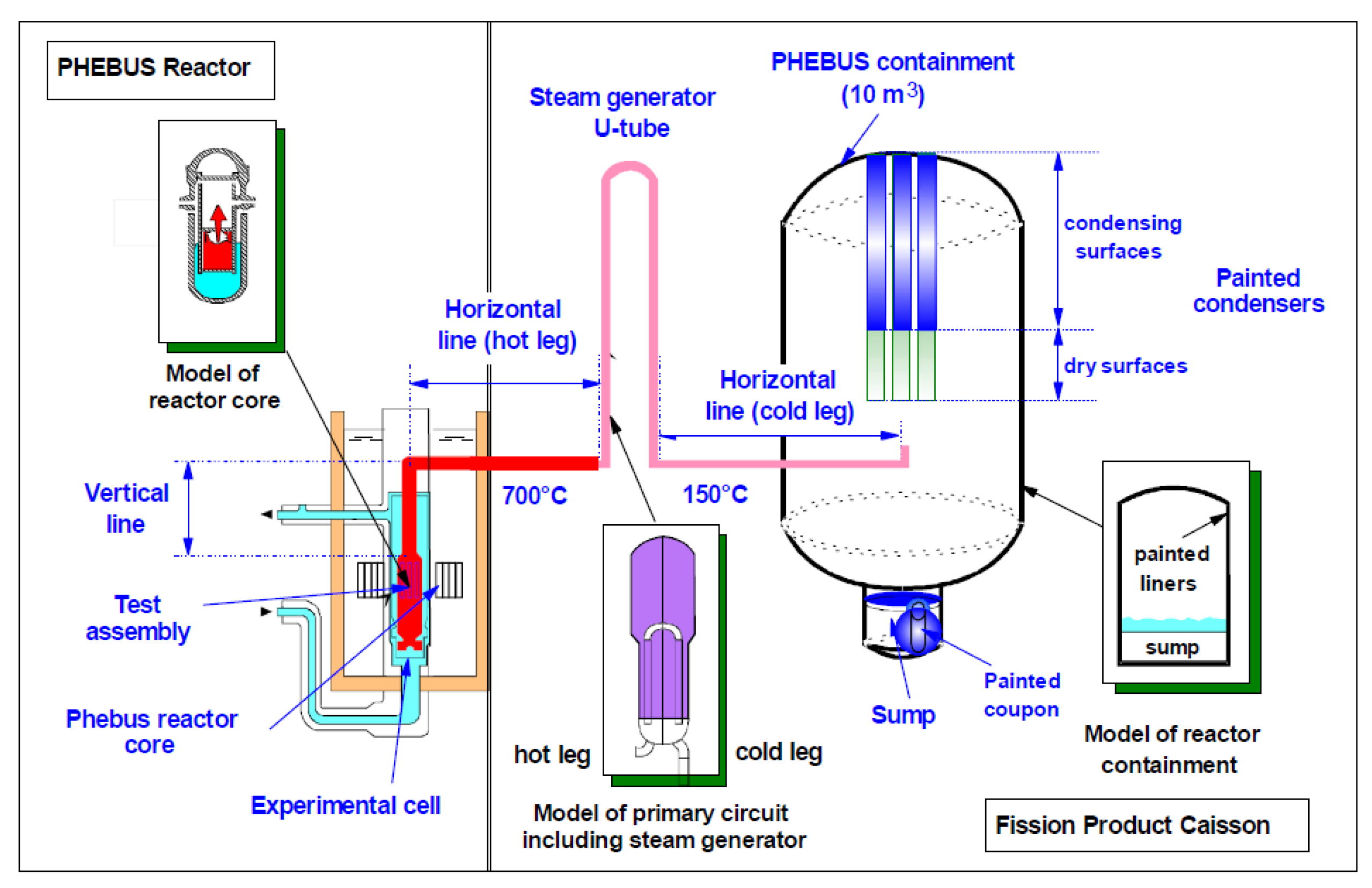
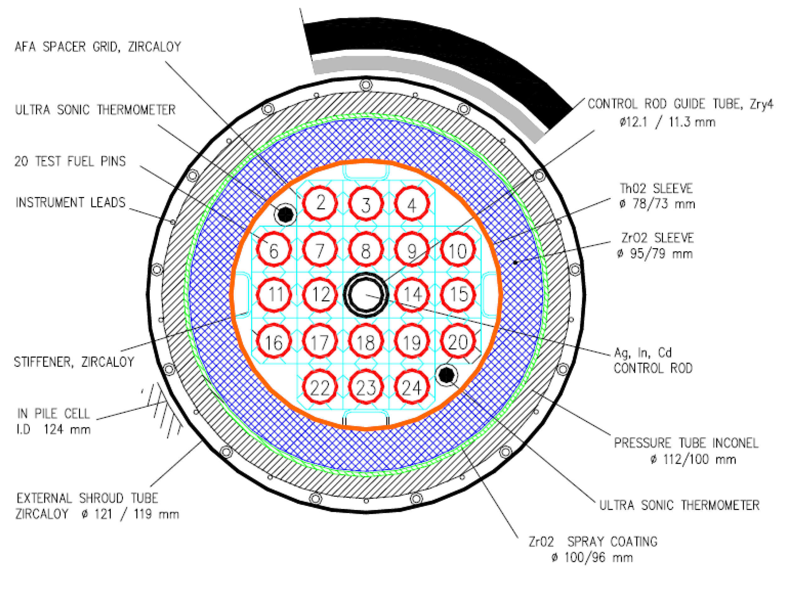
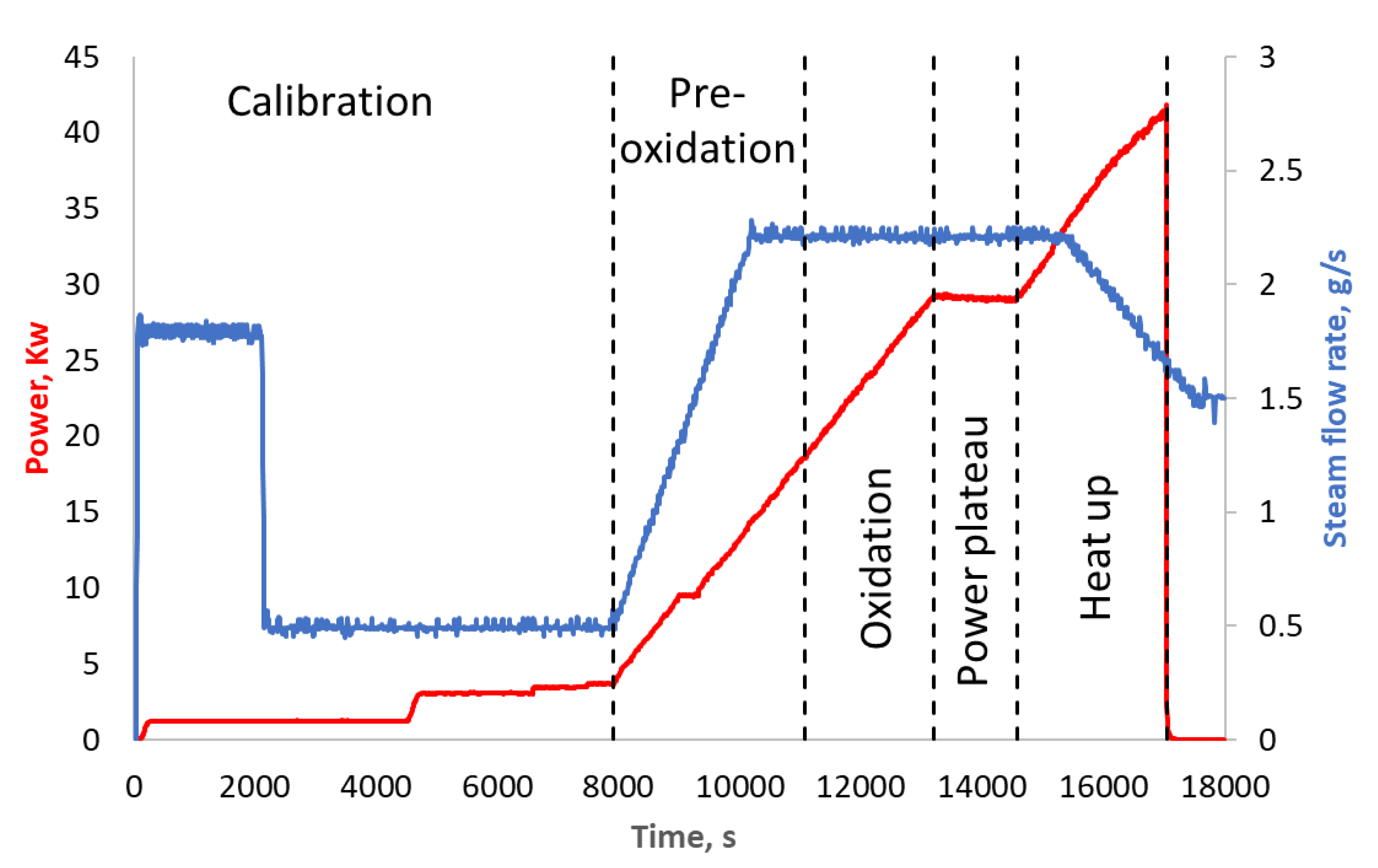
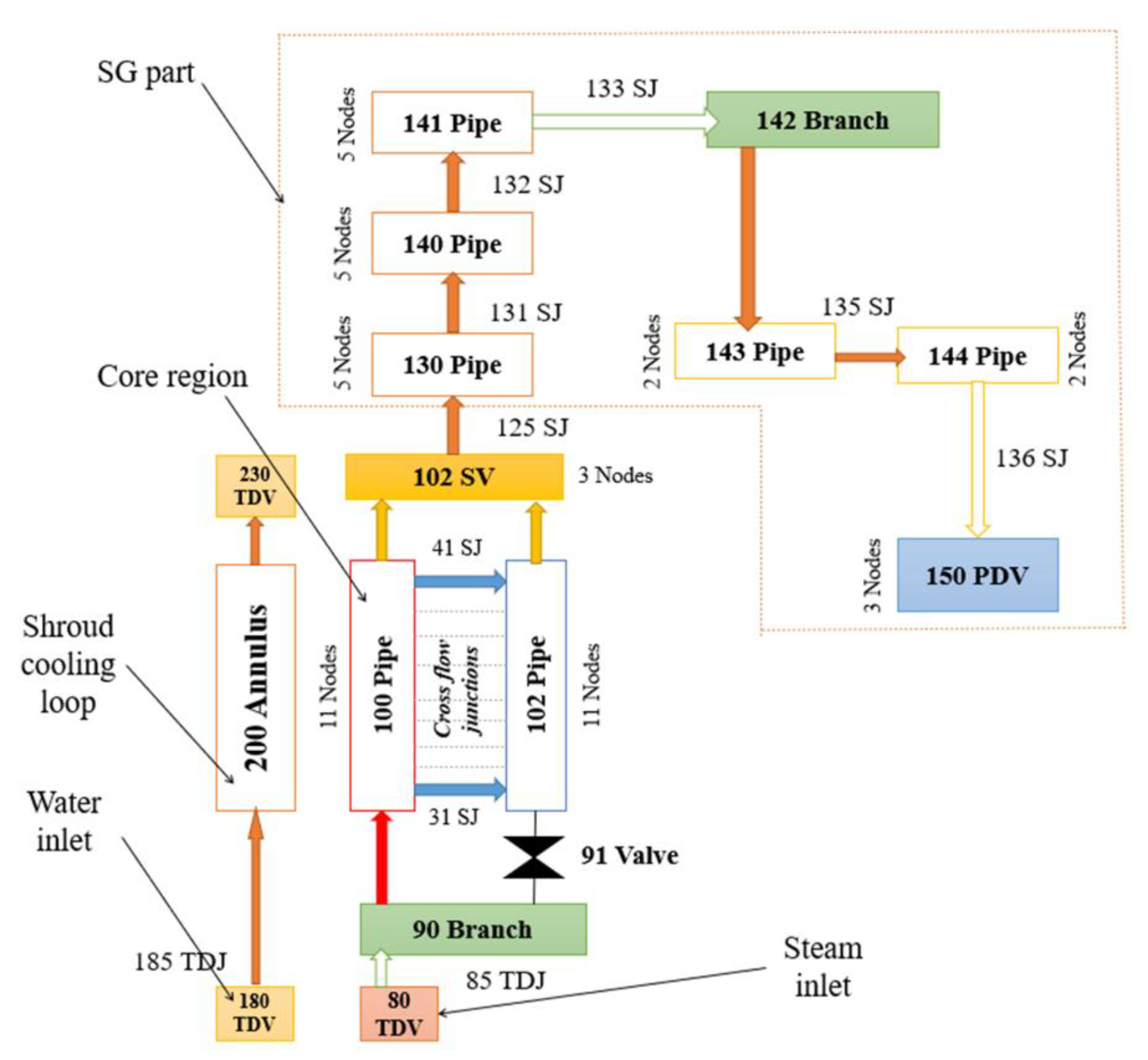
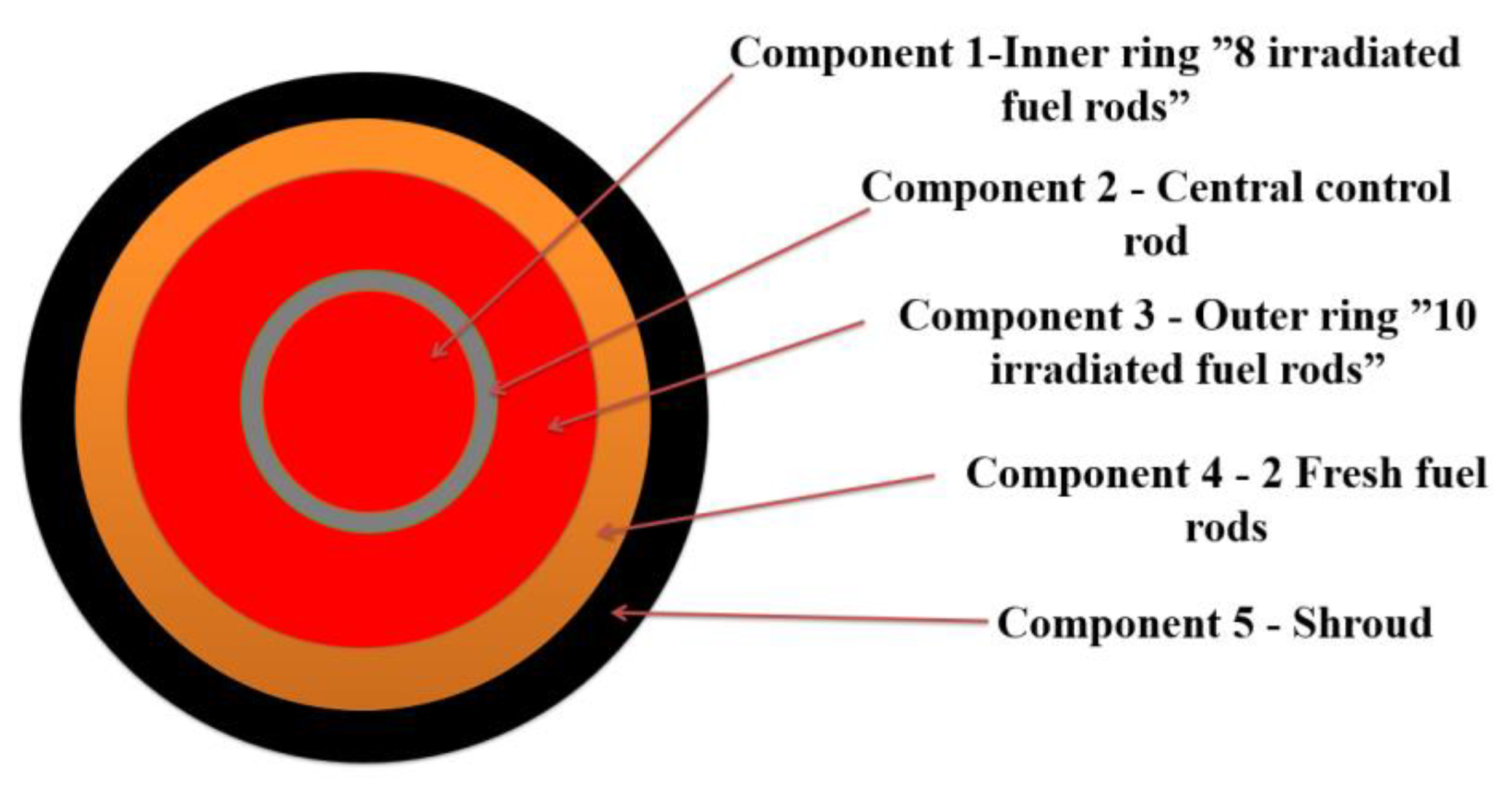
2.1. PHEBUS FPT-1 Test and RELAP/SCDAPSIM Model

The PHEBUS FPT is a light water reactor (LWR) source term research program. This program was carried out by the IRSN and the Joint Research Centre of the Commission of the European Communities in collaboration with the USA, Canada, Japan, Korea, and Switzerland [9]. The main objective of the PHEBUS FPT-1 test program is to study the release, transport, and retention of fission products under representative severe accidents conditions in LWR [11]. Different computer codes have been used for modelling PHEBUS tests, which allow the validation of severe accident models in the future.
The test facility consists of core, cooling circuit, pressurized water loop, test bundle, injection loop, steam generator, and containment vessel (Figure 1). The PHEBUS FPT-1 test bundle, representing PWR reactor fuel assembly, consists of 20 fuel rods (2 fresh and 18 irradiated) and 1 Ag-In-Cd control rod (Figure 2). Irradiated fuel rods have different burn-up of approximately 23.4 GWd/tU. This test is roughly equal to 1/5000 scale factor to general PWR 900 MW [11].
Figure 3 shows bundle power during the test and steam flow rate through the bundle (measurement data). PHEBUS FPT-1 test is divided into separate phases: calibration (0 to 7900 s); pre-oxidation (7900 s to 11,060 s); oxidation (11,060 s to 13,200 s), power-plateau (13,200 s to 14,580 s), and heat-up (14,580 s to 17,039 s) [11]. These phases are distinguished according to the power and steam flowrate changes through the bundle during experiment.
The RELAP/SCDAPSIM severe accident code was used for PHEBUS FPT-1 modelling. This computer code has been developed for the best estimate simulation of LWR coolant systems during normal operation and severe accident conditions [13,17]. RELAP/SCDAPSIM code consist of two parts: the RELAP part calculates the overall thermal hydraulic response; the SCDAP part includes user-selectable reactor component models for LWR fuel rods, and includes models to treat the later stages of severe accident including debris and molten pool formation, debris/vessel interaction, and the structural failure of vessel structures.
In this work, a previously developed model was used [18]. Figure 4 presents a schematic view of axial nodalization of RELAP model for PHEBUS facility. In this model only the core region with a shroud cooling loop and “U” pipe which imitates the steam generator were considered. Due to limitations of RELAP/SCDAPSIM code, it is not possible to evaluate processes in the containment. The SCDAP part describes the PHEBUS FPT-1 bundle. As it is presented in Figure 5, the PHEBUS FPT-1 bundle model consists of 5 SCDAP components: 1—irradiated fuel rod (inner ring, 8 fuel rods), 2—control rod, 3—irradiated fuel rod (outer ring, 10 fuel rods), 4—fresh fuel rod (2 fuel rods), and 5—shroud. All components were developed according to the PHEBUS FPT-1 test bundle (Figure 2). The shroud component contains all the material layers of the PHEBUS facility. Radial nodalization of SCDAP shroud component is presented in Figure 6. More details and model descriptions can be found in references [17,18].

2.2. CORSOR-M Model for Evaluation of FISSION Release

As described above, the prime focus is on the two RELAP/SCDAPSIM calculation results: total hydrogen generation and Cs/I release fraction from the fuel. Cs and I release from the fuel are defined as one of the figures of merit in the MUSA project. However, there are limitations in the LEI, which used RELAP/SCDAPSIM code version for modelling the fission product release from the fuel. The RELAP/SCDAPSIM code version that we used can model fission product release from the gap as a sum of three non-condensable gases (Xe+Kr+He) and a sum of two soluble gases (CsI+CsOH).
Taking all described limitations into account, it was decided to calculate Cs/I release based on the CORSOR-M [16] model. This is a simple model, which evaluates fission product release from the fuel only, according to fuel cladding temperature. The CORSOR-M model correlates the fractional release rate coefficient using an Arrhenius formula in the form [16]:
k = k 0 exp ( Q R T ) ,
where k is the release rate coefficient, k0 and Q are species-dependent constants (min−1 and kcal/mol), T is the absolute temperature (K), and R is the gas constant 1.987 × 10⁻³ in (kcal/mole-K).
In the open literature, it is possible to find many different values of k0 and Q for different species and several modifications of the CORSOR model. In this work, we are based on literature [16], according to which Cs and I have the same constants: k0 = 2 × 10⁵ min−1; Q = 63.8 kcal/mol. For this reason, the calculation results will be the same.
The mass of the species released from the fuel is calculated by the formula:
F P r = F P ( 1 exp ( k · Δ t ) ,
where FP is the mass of the species at the start of the time step, and Δ t is the time difference of the time step.
The CORSOR-M model for the evaluation of the fission product release is used in other severe accident codes like MELCOR [19,20], ATHLET-CD [21], and others.
The RELAP/SCDAPSIM code has the ability to input control system data. This option can be used to compute additional quantities from the normally computed quantities. There is a possibility of choosing different control component types such as SUM, MULT, DIV, DIFFRENIT, INTEGRAL, FUNCTION, etc. [22]. Taking advantage of these possibilities, the CORSOR-M model was included in the developed model of the PHEBUS FPT-1. That enabled us to calculate fractional release rate coefficients (by Equation (1)) at each calculation time step using RELAP/SCDAPSIM calculated temperatures in the different components at different nodes. Calculated fractional release rate coefficients were averaged according to number of axial nodes and components used for the modelling of the PHEBUS FPT-1 bundle. With this average release rate coefficient, using Equation (2), the mass of the Cs and I released from the fuel is calculated. The initial mass of Cs and I was given by IRSN. From there, the release fraction was calculated. Thus, Cs and I release fraction was calculated at each calculation time step using fuel rod cladding temperatures calculated by RELAP/SCDAPSIM models.

2.3. Uncertainty Quantification Using BE Approach for PHEBUS FPT-1 Test

Uncertainty quantification was made using the BE approach. The BE approach was developed on design basis accident analysis, but this approach could be considered as an application to different scenarios of nuclear reactor severe accidents [14].
There are many methodologies which could be used for the application of the BE approach to the nuclear installations; most of the methodologies are described in IAEA safety report series No. 52 [10]. LEI is using GRS methodology [14] for these tasks. GRS methodology is based on Monte-Carlo methods for randomizing the uncertain parameters and uses the statistical tool SUSA [15]. The main advantage of GRS methodology is that the number of calculations depends only on the desired probability content and confidence level described by Wilks’ formula [23]. The GRS methodology’s disadvantage is that initial uncertain parameters must be independent form each other.
The list of uncertainty parameter specifications (reference values, their ranges, and probability distribution function (PDF)) is the first step for the GRS method application. The list of uncertain parameters and their uncertainty parameters was discussed with other MUSA project members, and it was included in Work Package 2 of the project. In this work, it was decided to evaluate uncertainties that come from the thermal properties of materials (Table 1) and modelling parameters of SCDAP (Table 2). The ranges of the uncertainty analysis, as well as PDF, were chosen according to experience [17,18,24] and engineering judgment. For some SCDAP parameters the uncertainty ranges reach 50% from the initial value, because it was not known how strong an effect these uncertainties will give to the calculation results in severe accident conditions. Normal PDF is used for the parameters whose nature is clear. Uniform PDF usually is used when the distribution of these parameters is not clear.
For uncertainty analysis, it was decided to apply 95% probability and 95% of confidence level for the two-sided tolerance limit. According to Wilks’ formula, to get selected uncertainty parameters at least 93 calculations must be performed. In this study, it was decided to perform 100 calculations in case some calculations are terminated due to numerical or other reasons.
For the sensitivity analysis, there are many different correlations for the evaluation of the influence of initial uncertain parameters on the results. For sensitivity analysis in the nuclear field, Pearson correlation, Spearman rank correlation, and Kendall rank correlation are most commonly used.
Pearson correlation coefficient (r) is considered as a measure of the linear correlation between two variables. It applies to the parametric method. The Pearson correlation coefficient varies from −1 to +1. The closer the coefficient to +1 or −1, the stronger linear correlation (positive or negative) between the variables.
Pearson correlation coefficient is defined as [26]:
r ( A ,   B ) = i = 1 n ( x i X ¯ ) ( y i Y ¯ ) ( i = 1 n ( x i X ¯ ) 2 i = 1 n ( y i Y ¯ ) 2 ) 0.5  
X ¯ = 1 n i = 1 n x i ,
Y ¯ = 1 n i = 1 n y i .
where: X ¯ Y ¯ ; the means of variables X, Y, and n is the size of the sample.
The Spearman rank correlation coefficient ( r S ) applies to the non-parametric method [27,28]. It is considered the Pearson correlation coefficient applied to the ranks R. It has the same range as the Pearson rank correlation coefficient.
The Spearman rank correlation is defined as [28]:
r S ( A ,   B ) = i = 1 n ( R ( x i ) 1 2 ( n + 1 ) ) ( R ( y i ) 1 2 ( n + 1 ) ) ( i = 1 n ( R ( x i ) 1 2 ( n + 1 ) ) 2 i = 1 n ( R ( y i ) 1 2 ( n + 1 ) ) 2 ) 0.5  
where R means rank of variables X, Y.
The Kendall rank correlation coefficient ( τ ) applies to non-parametric method [27,28,29]. It has the same range as the Pearson and the Spearman rank correlation coefficient (from +1 to −1). However, the Kendall coefficient ( τ ) is defined as [29]:
τ = C D 0.5 n ( n 1 )   ,
where C means concordant, D—discordant and n—the number of observations.
  • Concordant (C): the ranks agree for any pair of observations; Xi > Xj and Yi > Yj, or Xi < Xj and Yi < Yj,
  • Discordant (D): the ranks disagree for any pair of observations; Xi > Xj and Yi < Yj or Xi < Xj and Yi > Yj.
When the variables have the same ranks, they are called tied pairs. Kendall rank coefficient ( τ b ) for tied pairs is defined as:
τ b = C D 0.5 n ( n 1 ) T 0.5 n ( n 1 ) U ,
where T means tied pairs in X (only if Xi = Xj), U means tied pairs in Y (only if Yi = Yj).
The Kendall rank correlation coefficient gives a positive or negative strong correlation between variables if its value is close or equal to +1 or −1. There is no correlation between variables if its value is equal to or close to 0.
Another important parameter for the sensitivity analysis is the determination coefficient (R2) for the chosen correlation. This coefficient is defined as the square of the population correlation coefficient between the code result Y and the variable Y ¯ obtained from linear regression Y on the parameters X1, X2 …, Xnpar. It shows the proportion of the total variation of code results Y explained by the overall influence of the uncertain parameters X1, X2 …, Xnpar as modelled by linear regression of Y on the parameters [30]:
R 2 = V a r ( Y ^ ) V a r ( Y )  
R2 is used to assess the quality of the correlation coefficient. R2 ranges are between 0 and +1. According to common practice, if the value of R2 is less than 0.6 the regression coefficient of the sensitivity parameters may be incorrect because of too many unexplained parameter variations. For such cases, it is recommended to use different methodologies for the evaluation of the parameter sensitivities to calculation results. Different methods and their comparison may be found in the IAEA safety report series No. 52, Table 6 [10]. Thus, before performing sensitivity analysis using GRS methodology it is necessary to check the values of R2.
Using different (Pearson, Spearman or Kendall) correlations, the R2 values can vary. For the sensitivity analysis, it is better to choose those correlations that give higher R2 values.

3. Results and Discussions

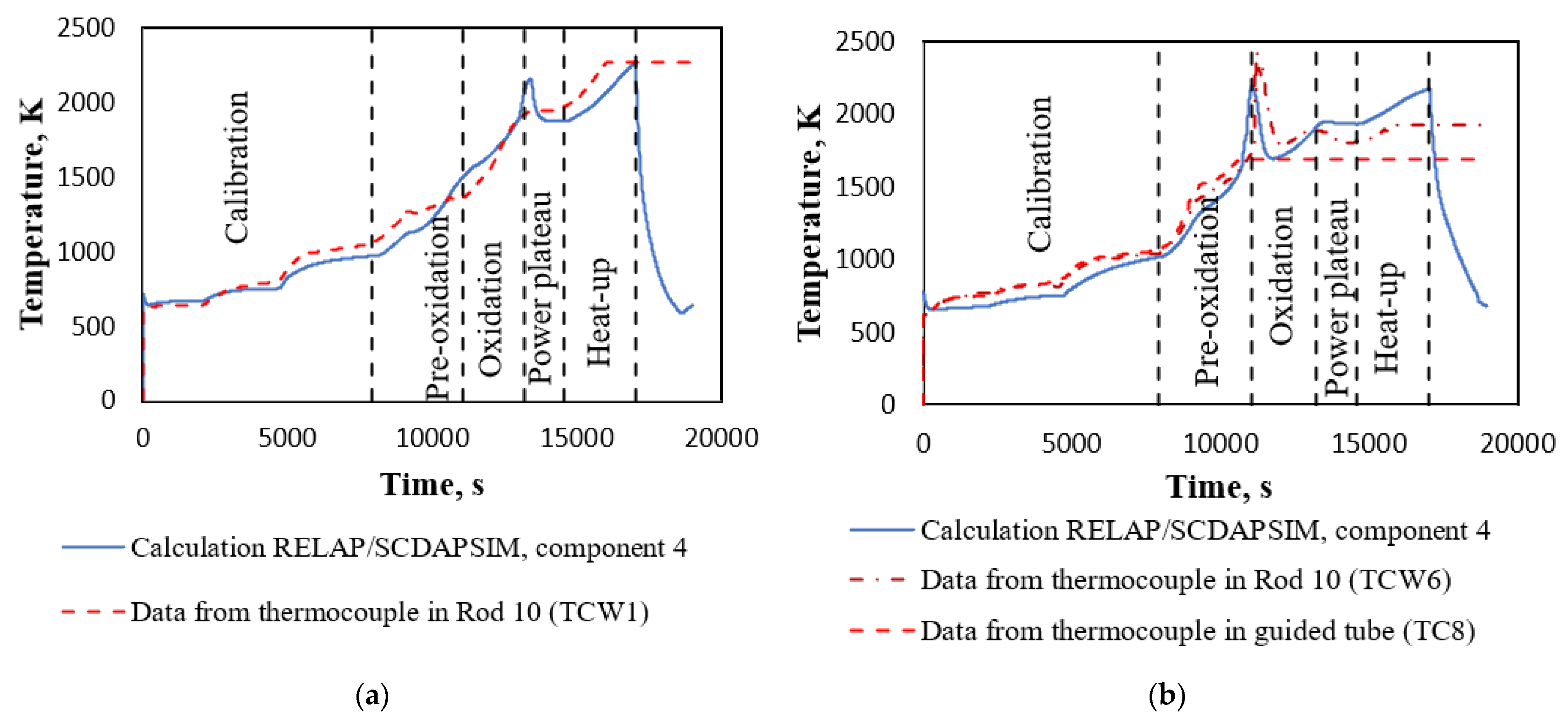
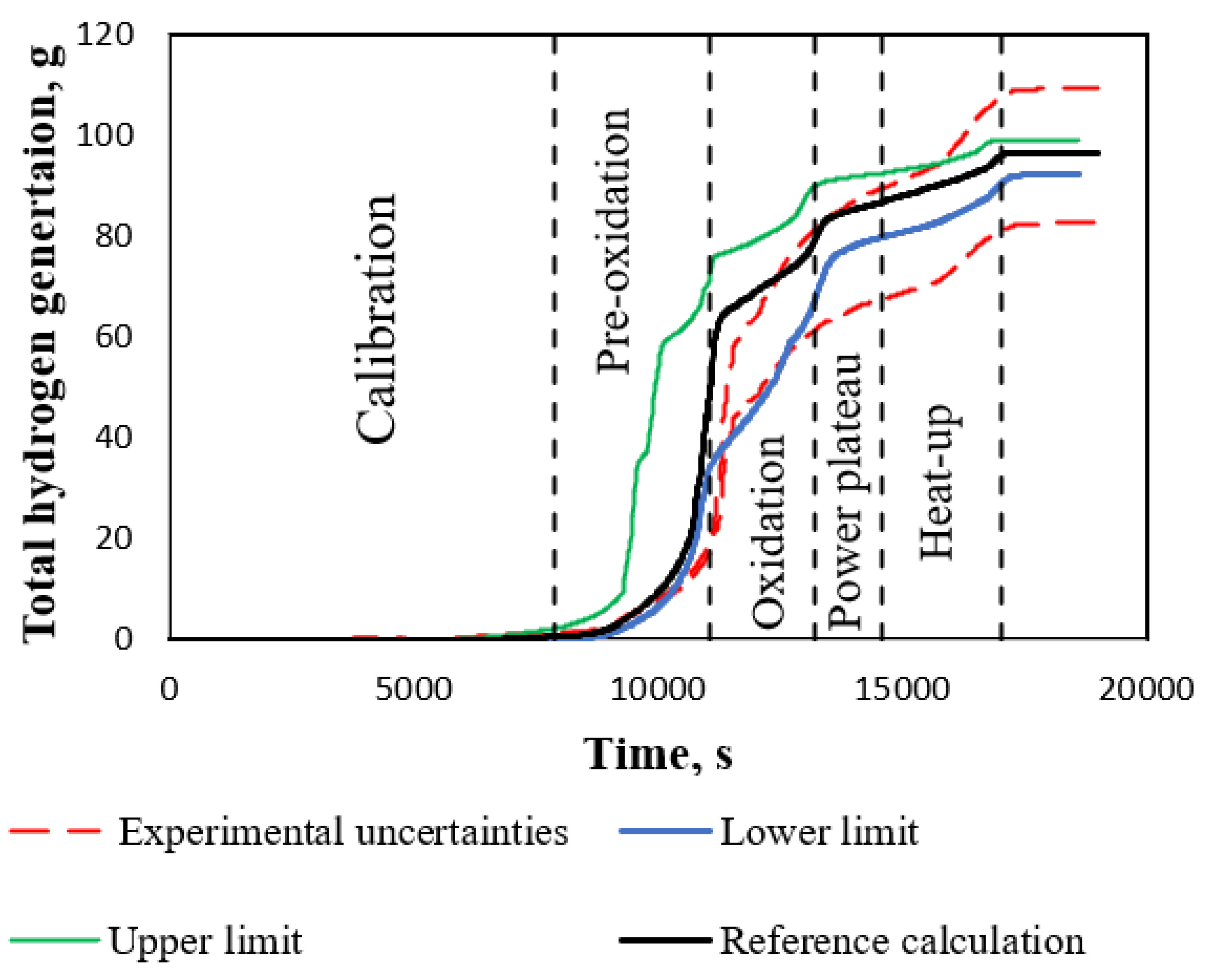
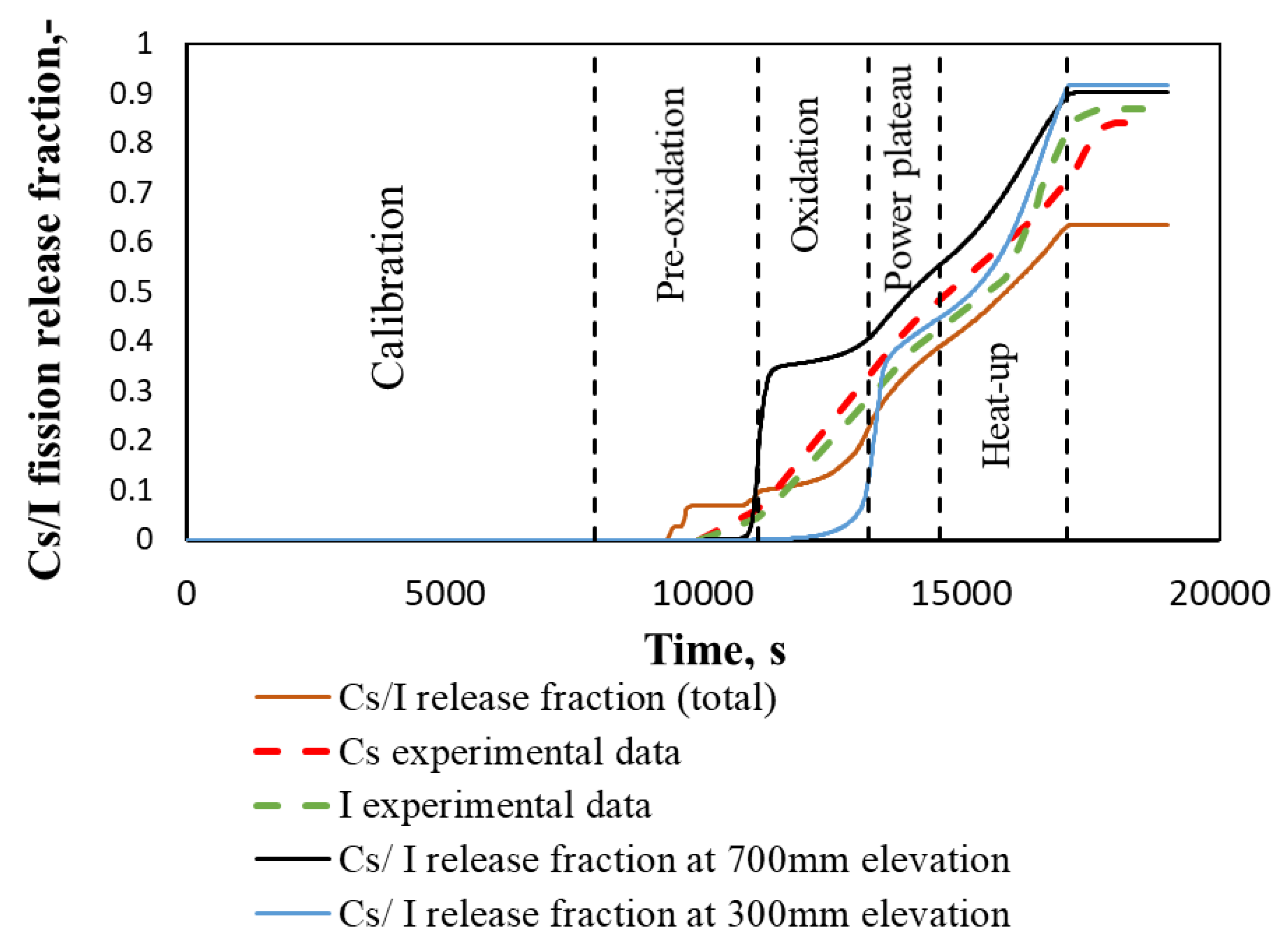
3.1. Results of Reference Case Calculation

Results of PHEBUS FPT-1 test reference calculation should be adequate to the experimental data. In this case, the results of the reference case calculation were compared with experimental data provided by IRSN [11]. A comparison of the calculated temperature of fuel rod claddings with experimental data at 300 mm and 700 mm elevation from the bottom of the active fuel is presented in Figure 7. From the temperature comparison, it is clear that calculated temperature is lower in the pre-oxidation and oxidation phases, but for power-plateau phase it is higher than in the experimental data. In addition, comparison results indicate earlier (~370 s) start of the oxidation process in the calculation results (earlier calculated temperature peak in Figure 7b).
According to PHEBUS FPT-1 report [11], the experimental uncertainty for the total hydrogen generation experimental data is ±5% on the raw signal of the sensor, which induces a variation of ~±14% on the estimate value of the total generated mass of hydrogen. As a result, the total mass of hydrogen released during the FPT1 test was evaluated at 96 ± 13 g (corresponding to the oxidation of ~2.18 kg of Zry i.e., ~64% of the initial inventory), see Figure 8. Comparing the experimental data with the results of the reference case calculation at the end of the pre-oxidation and beginning of the oxidation phases, the calculated value of hydrogen generation is overestimated. However, in the later phases the calculated value is in the range of experimental uncertainties and at the end of the calculation it is very close to experimental data ~96 g.
The release of Cs/I was calculated using the CORSOR-M model described in Section 2.2. Temperatures in the different elevations of the bundle, necessary for the calculation of release, were taken from RELAP/SCDAPSIM calculations. These data were provided to CORSOR-M model to evaluate the Cs/I release fraction (Figure 9). The calculated Cs/I release fraction, based on the calculated fuel temperature at 300 mm and 700 mm elevation, overestimates experimental data [31,32]. However, the calculated total Cs/I release fraction is below the experimental data for ~30% at the end of the heat-up phase. Such a result could be due to several reasons, such as the simplifications of the CORSOR-M model or discrepancies in the temperature calculation of the RELAP/SCDAPSIM code. Nevertheless, the comparison of the temperatures at elevations 300 and 700 mm was in good agreement with the experimental data; the calculated temperatures in other elevations of the experimental bundle could have bigger differences with experimental data. The detailed evaluation of temperature behaviour in the experimental bundle and analysis of discrepancy in calculated and measured fractions of releases were not provided in this article due to the fact what this work concentrates on the application of the BE methodology for the experiment modelling at severe accident conditions.

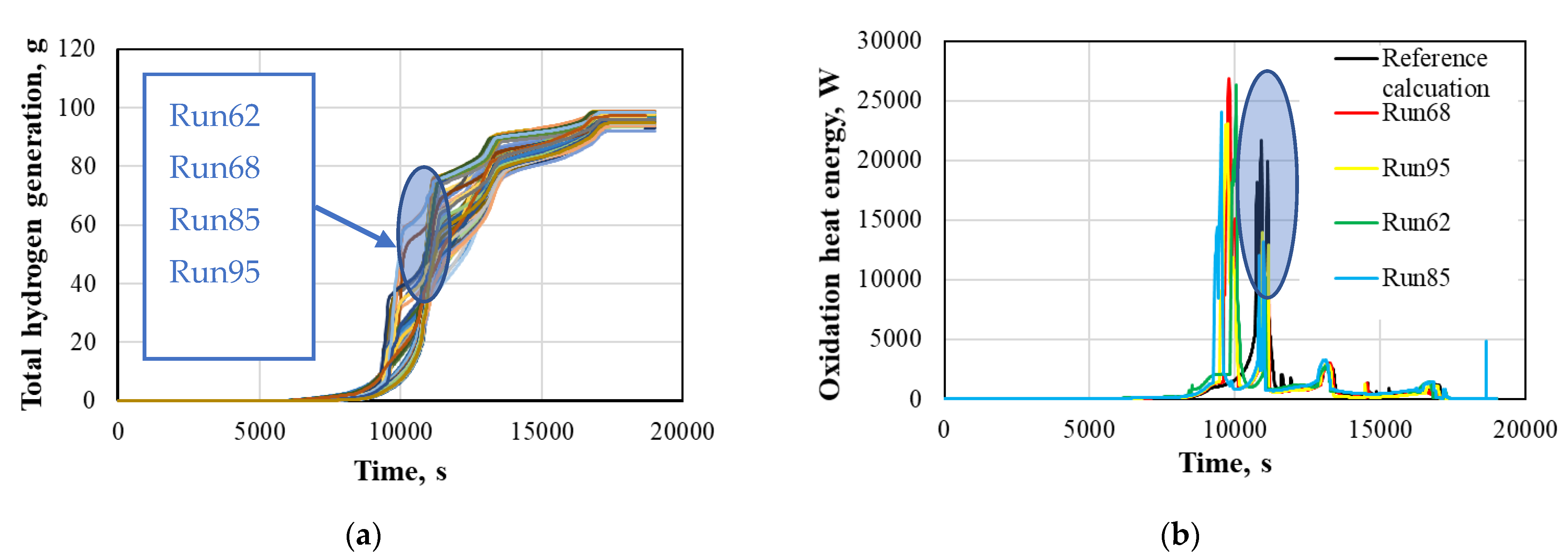
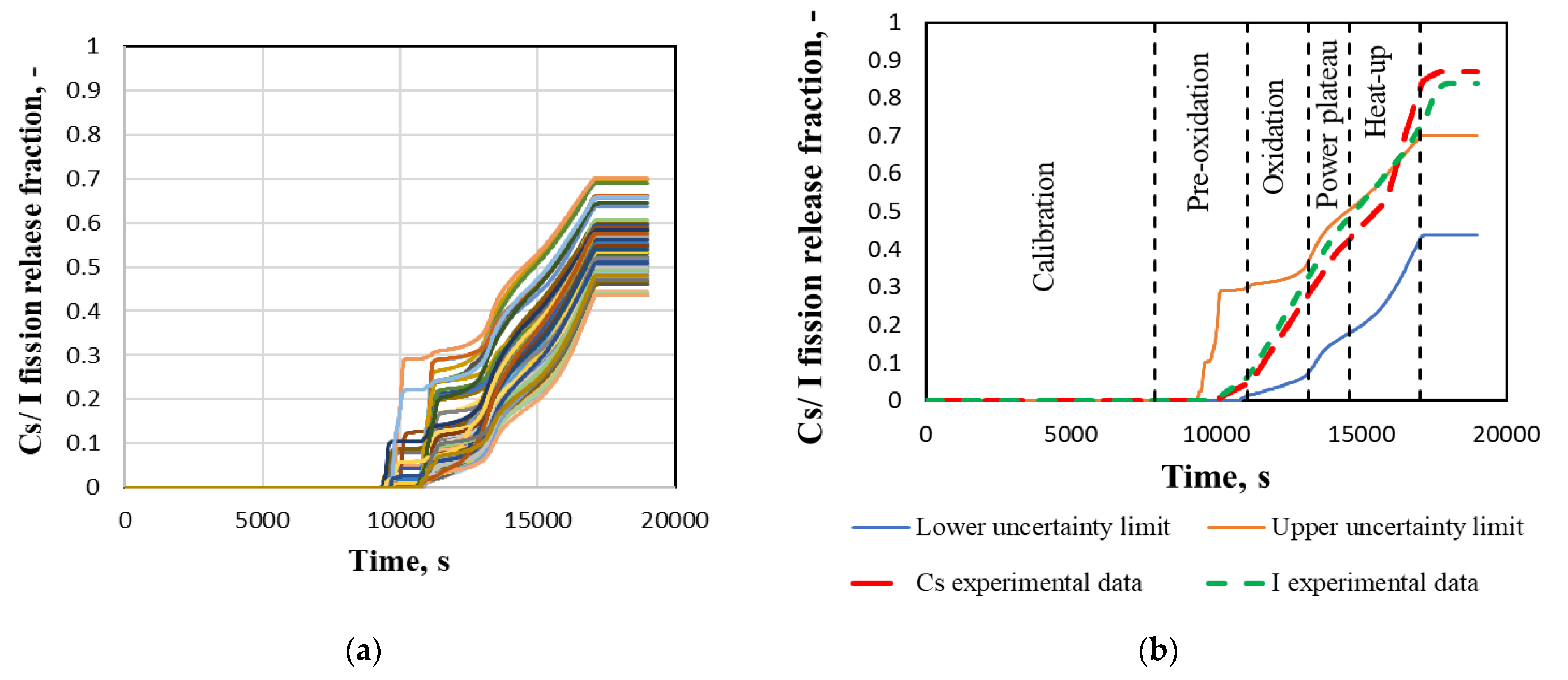
3.2. Results of Uncertainty Analysis

In Figure 10a, calculation results of total hydrogen generation for 100 calculations (runs) are presented. All 100 RELAP/SCDAPSIM calculations reached heat-up phase and bundle cool-down conditions. Some calculations were terminated before the given end of the time of calculation, but this does not affect the results that are analysed in this work. Thus, all 100 calculation results were considered for the uncertainty as well as sensitivity analysis. Analysing the calculation results, different behaviours were noted from four runs (samples of parameters). In these four runs, earlier oxidation in the pre-oxidation phase (Figure 10b) was observed. Such results were achieved due to a sample of the parameters which caused earlier oxidation. For three runs (runs 62, 68, and 95) of four, it was noticed that the parameters P22 (temperature for the failure of oxide shell on an outer surface of fuel and cladding) and P23 (fraction of oxidation of fuel rod cladding for stable oxide shell) had maximum values and P24 (hoop strain threshold for double-sided oxidation) had its minimum values according to reference values. Parameters P22–P24 are related to the oxidation process, and in the current situation, a combination of these parameters caused earlier oxidation phenomena even during the relatively low power region. Another run (run 85) which had earlier oxidation was due to the values of parameters P12 (ZrO2 thermal conductivity) and P31 (gamma heat fraction.). In this run, P12 had values near the minimum range of this parameter and P31 had values near the maximum range of this parameter. P12 affects the heat transfer from the bundle—lower values of ZrO2 thermal conductivity give more heat to the bundle. Gamma heat fraction (P31) means the fraction of power used to directly heat the coolant by gamma heating. The combination of these parameters caused earlier oxidation, by comparison to the reference case and other runs (Figure 10b).
The upper and lower uncertainty limits for the total hydrogen generation are provided in Figure 8. The upper and lower uncertainty limits are bounding the experimental data of total hydrogen generation almost in the whole-time interval. Some overestimation appears is in the oxidation phase. However, when comparing the values of total generated hydrogen at the end of the calculation, experimental uncertainties are higher than the upper and lower uncertainty limits.
In Figure 11a 100 calculation results of Cs/I release fraction are presented. The spread of the results between the lowest and the highest value at the end of calculations is about ~30%. Four calculation results (the same as in the case of hydrogen generation) give the early oxidation. The reason for this is explained above for hydrogen generation. This increasing temperature in the bundle causes a high early release of fission products. In Figure 11b, the uncertainty upper and lower limits with 95% of probability and 95% of confidence level for Cs/I release fraction are presented. Upper and lower uncertainty limits are bounding experimental data until the middle of the heat-up phase. However, at the end of the experiment, the calculated upper uncertainty limit is ~20% lower than the experimental data. Possible reasons are discussed in Section 3.1 for reference calculation results.

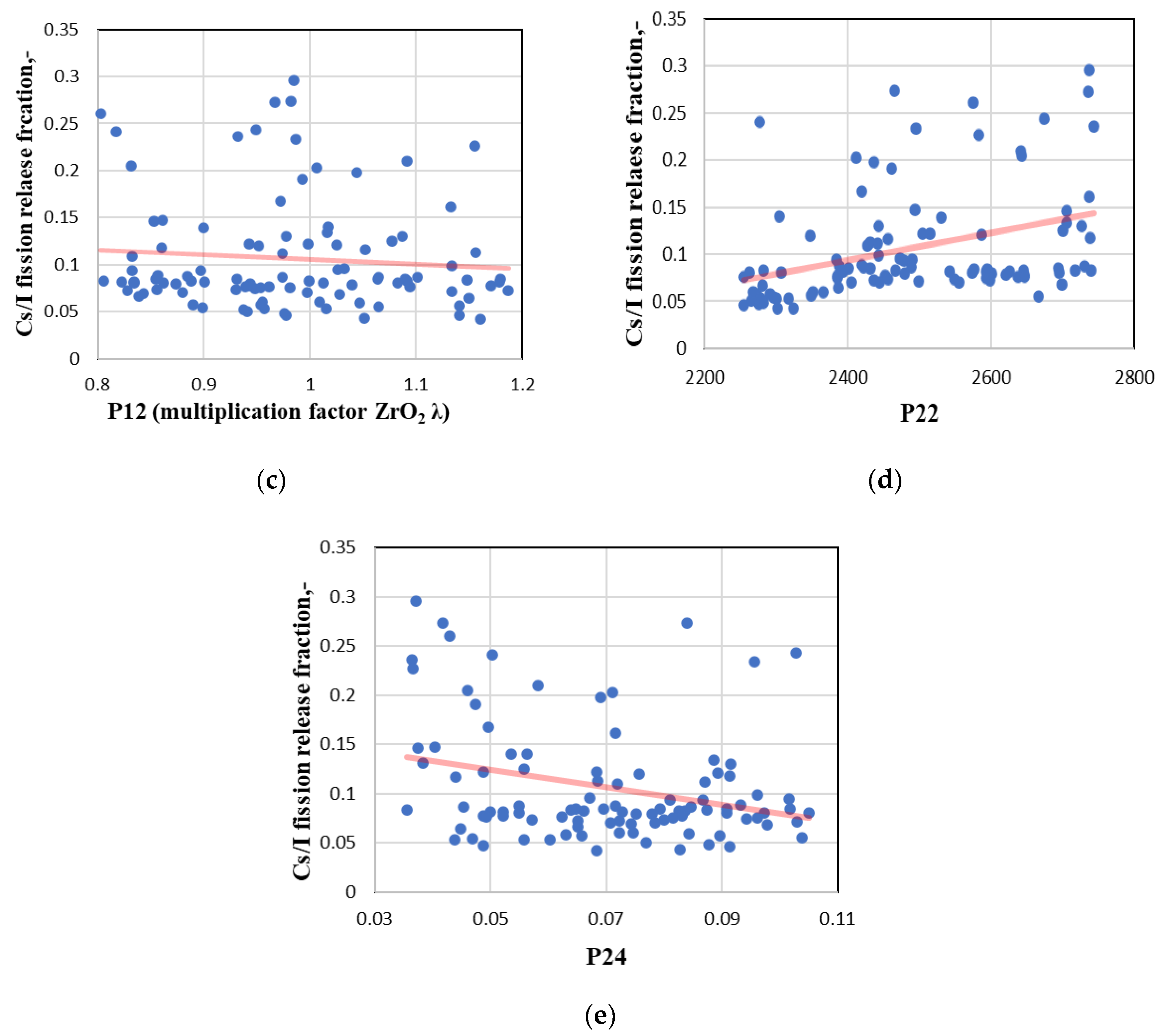
3.3. Results of Sensitivity Analysis

Sensitivity analysis started from the evaluation of R2 at different correlations. In Figure 12 the R2 for different correlations of total hydrogen generation and Cs/ I release fraction are presented. All analysed correlations give very similar behaviour of R2 during the test. Pearson and Spearman correlations give R2 values higher than 0.6 during all calculation time, except for a small period of time at the end of the pre-oxidation phase for hydrogen generation and the second half of the oxidation phase for Cs/I release fraction. Spearman’s rank correlation had higher values of R2 coefficient during all test phases. This is especially important when the R2 coefficient is decreasing due to the complex and transient modelling processes (exclusively for pre-oxidation, oxidation, and power-plateau phases). For this reason, it was decided to use Spearman’s rank correlation coefficient to evaluate the influence of uncertain parameters.
Sensitivity analysis using Spearman’s rank correlation was provided for the whole calculation period. The influence of the parameters on the calculation results changed at different experimental phases over time. Thus, for the simplification, it was decided to present the influence of the uncertain parameters on the calculation results at the current time at each experimental phase (Table 3). The most influenced (dominant) parameter through the test with negative influence (increasing value of the parameter—result value is decreasing) is ZrO2 layer thermal conductivity of shroud (parameter P12). The importance of other parameters changes at the different experimental phases with the application of different physical processes. In the calibration and pre-oxidation phases, the parameter which corresponds to the gamma heat fraction (P28) has a significant influence. During the oxidation phase, the SCDAP parameters related to the fuel cladding rupture (P22 and P24) have great influence to calculation results. For the power-plateau and heat-up phases, the parameters related to the geometrical date of grid spacers (P29 and P30) have the biggest influence on the calculation results.
The results of the sensitivity analysis of Cs/I release fraction calculation showed sudden changes in influential parameters, especially in the pre-oxidation and oxidation phases). Thus, it was decided to make scatter plots for the most influenced uncertain parameters for the calculation results of Cs/I release fraction at these phases. For the pre-oxidation phase, at a time 9000 s, scatter plots and regression lines were prepared for zirconium dioxide thermal conductivity (P12) and gamma heat fraction (P28). For the oxidation phase, at a time 12,500 s, scatter plots and regression lines were prepared for zirconium dioxide thermal conductivity (P12), temperature for the failure of oxide shell on an outer surface of fuel (P22), and cladding hoop strain threshold for double-sided oxidation (P24) (Figure 13).
Figure 13 confirms the influence of the analysed parameters on the calculation results. However, in some scatter plots, significant dispersion of the results may be seen (Figure 13b,c). The reason for this (as discussed in the results of the uncertainty analysis) could be a combination of different parameters which could give scattered results. It could also be related to the chosen wide ranges of parameters. Such dispersion of the results reduces the total influence of the analysed parameters.

4. Conclusions and Recommendations

This article concentrates on the application of the BE methodology for the experiment, which imitates severe accident conditions at LWR. The main attention is focused on hydrogen generation and fission product release from the bundle. Numerical analysis of the PHEBUS—FPT1 test was provided using the RELAP/SCDAPSIM severe accident code. Due to the limitations of the RELAP/SCDAPSIM code version used in the LEI, the CORSOR-M model was included into PHEBUS—FPT1 model to evaluate fission product release from the fuel. Calculation results of the reference case presented an adequate agreement with experimental data, except for calculation results of Cs/I release fraction at the heat-up phase (calculation results are below the experimental data for ~30%).
Uncertainty quantification of the PHEBUS FPT-1 test modelling results was fulfilled using SUSA statistical tool by providing uncertainty and sensitivity analysis. Upper and lower uncertainty limits of total hydrogen generation calculation results are bounding the experimental data in all phases except the heat-up phase, where experimental uncertainties are even wider. Calculated Cs/I release fraction upper and lower uncertainty limits are bounding the experimental data in all phases except the heat-up phase, where the upper uncertainty limit is ~ 20% lower than the experimental data. This result indicates that the coefficients used in the current CORSOR-M model version should be revised, and great attention should be paid to the SCDAP parameters and models which have a significant influence on the modelling of the late bundle degradation phases.
For the sensitivity analysis, the Spearman rank correlation was chosen. Results showed that the thermal conductivity of the ZrO2 layer of the shroud has the dominant influence on calculation results. Other important parameters are different at different experimental phases. The parameter corresponding to the gamma heat fraction is important at the calibration and pre-oxidation phases, the SCDAP parameters are important at the fuel cladding rupture, and parameters related to the geometrical date of grid spacers are important at power-plateau and heat-up phases. The remaining parameters have an insignificant influence. Scatter plots provided for the most influencing parameters at the pre-oxidation and oxidation phases confirm the influence of the analysed parameters on the calculation results.
Recommendations:
  • Results of this work indicate that it is necessary to revise coefficients used in the current CORSOR-M model version or use other modelling codes or methods which take into account more parameters (not only temperature) for the propagation of fission product release.
  • Material properties (especially thermal conductivity) of the shroud of the PHEBUS facility have a significant impact on calculation results. This should be evaluated in the model development.
  • SCDAP parameters should be selected according to the code developer recommendations (these are recommendations for PWR or BWR plant application). However, for the experimental facility, the values and range of some parameters are not clear. Results of the provided sensitivity analysis showed parameter influence on the calculation results. This simplifies the selection of parameter values for further analysis. Special attention should be paid to SCDAP parameters related to the fuel cladding rupture at the oxidation phase.

Author Contributions

Methodology, T.K.; validation, N.E. and T.K.; formal analysis, N.E. and T.K.; writing—original draft preparation, N.E.; writing—review and editing, T.K.; visualisation, N.E.; supervision T.K.; T.K.; project administration. All authors have read and agreed to the published version of the manuscript.

Funding

This project has received funding from the Euratom research and training program 2014–2018 under grant agreement No. 847441.

Institutional Review Board Statement

Not applicable.

Informed Consent Statement

Not applicable.

Data Availability Statement

Open access to the MUSA research data is regulated by Article 29.3 of grant agreement No. 847441 between EURATOM and the MUSA participants. The project deliverable “Data Management Plan” describes the data management life cycle for the data to be collected, processed, and/or generated during this Horizon 2020 project.

Conflicts of Interest

The authors declare no conflict of interest.

References

  1. IAEA. Energy, Electricity and Nuclear Power Estimates for the Period up to 2050; Reference Data Series No. 1; International Atomic Energy Agency: Vienna, Austria, 2018; p. 7. [Google Scholar]
  2. IAEA. IAEA Report, Climate Change and Nuclear Power; International Atomic Energy Agency: Vienna, Austria, 2020; pp. 16–19. [Google Scholar]
  3. OECD. Status Report, Long-Term Management and Actions for a Severe Accident in a Nuclear Power Plant; OECD: Paris, France, 2021. [Google Scholar]
  4. IAEA. Safety glossary. In Terminology Used in Nuclear Safety and Radiation Protection; International Atomic Energy Agency: Vienna, Austria, 2007. [Google Scholar]
  5. Zhang, Y.P.; Niu, S.P.; Zhang, L.T.; Qiu, S.Z.; Su, G.H.; Tian, W.X. A Review on Analysis of LWR Severe Accident. J. Nucl. Eng. Radiat. Sci. 2015, 1, 041018. [Google Scholar] [CrossRef]
  6. Ministry of Chernobyl. Ten Years after the Accident at the Chernobyl NPP; National Report of the Ukraine; Ministry of Chernobyl: Kiev, Ukraine, 1996. (In Russian)
  7. Povinec, P.P.; Hirose, K.; Aoyama, M. Fukushima Accident: Radioactivity Impact on the Environment; Elsevier: New York, NY, USA, 2013. [Google Scholar]
  8. IAEA. IAEA Report. Hydrogen Phenomena during Severe Accidents in Water Cooled Reactors; International Atomic Energy Agency: Vienna, Austria, 2021. [Google Scholar]
  9. IAEA. IAEA Safety Report Series, Accident Analysis for Nuclear Power Plant Series No 23; Vienna, International Atomic Energy Agency: Vienna, Austria, 2002. [Google Scholar]
  10. IAEA. IAEA Safety Report Series, Best Estimate Safety Analysis for Nuclear Power Plants: Uncertainty Evaluation No. 52; International Atomic Energy Agency: Vienna, Austria, 2008. [Google Scholar]
  11. IPSN. Final Report FPT1, IPSN/CRS/SEA/PEPF Report SEA1/00, IP/00/479; Institut de Protection et de Surete Nucleaire (IPSN): Cadarache, France, 2000. [Google Scholar]
  12. Herranz, L.; Beck, S.; Sánchez-Espinoza, V.; Mascari, F.; Brumm, S.; Coindreau, O.; Paci, S. The EC MUSA Project on Management and Uncertainty of Severe Accidents: Main Pillars and Status. Energies 2021, 14, 4473. [Google Scholar] [CrossRef]
  13. Allison, C.M.; Hohorst, J.K. Role of RELAP/SCDAPSIM in Nuclear Safety. Sci. Technol. Nucl. Install. 2010, 2010, 425658. [Google Scholar] [CrossRef]
  14. Glaeser, H. GRS Method for Uncertainty and Sensitivity Evaluation of Code Results and Applications. Sci. Technol. Nucl. Install. 2008, 2008, 798901. [Google Scholar] [CrossRef] [Green Version]
  15. Kloos, M.; Hofer, E. SUSA Version 3.5, User’s Guide and Tutorial; Gesellschaft für Anlagen- und Reaktorsicherheit (GRS) gGmbH: Köln, Germany, 2002. [Google Scholar]
  16. Kuhlman, M.R.; Lehmicke, D.J.; Meyer, R.O. CORSOR User’s Manual; NUREG/CR-4173; Battelle Columbus Labs: Columbus, OH, USA, 1985. [Google Scholar]
  17. Kaliatka, T.; Ušpuras, E.; Vileiniškis, V. Best Estimate analysis of PHEBUS FPT-1 test using RELAP/SCDAPSIM. In Proceedings of the 20th International Conference on Nuclear Engineering ICONE 20, Anaheim, CA, USA, 30 July–3 August 2012. [Google Scholar] [CrossRef]
  18. Vileiniskis, V.; Kaliatka, A. Best estimate analysis of PHEBUS FPT1 experiment bundle phase using ASTEC code ICARE module. Kerntechnik 2011, 76, 254–260. [Google Scholar] [CrossRef]
  19. Gauntt, R.O. Synthesis of VERCORS and Phebus Data in Severe Accident Codes and Applications, SAND2010-1633; Sandia National Laboratories (SNL), Albuquerque, NM, and Livermore: Livermore, CA, USA, 2010. [Google Scholar] [CrossRef] [Green Version]
  20. Darnowski, P.; Włostowski, M.; Stępień, M.; Niewiński, G. Study of the material release during PHÉBUS FPT-1 bundle phase with MELCOR 2.2. Ann. Nucl. Energy 2020, 148, 107700. [Google Scholar] [CrossRef]
  21. Lovasz, L.; Bals, C.; Hollands, T.; Köllein, C.; Aust-regesilo, H.; Pandazis, P.; Tiborcz, L.; Weber, S. ATHLET-CD Mod 3.2 Models and Methods Draft, GRS - P4 Vol. 2; Gesellschaft für Anlagen- und Reaktorsicherheit (GRS) gGmbH: Köln, Germany, 2019. [Google Scholar]
  22. RELAP5/MOD3.3 CODE MANUAL, Volume I: Code Structure, System Models, and Solution Methods, NUREG/CR-5535/Rev.1-Vol.I. December 2001. Available online: https://www.nrc.gov/docs/ML1103/ML110330200.pdf (accessed on 3 October 2021).
  23. Wilks, S.S. Statistical Prediction with Special Reference to the Problem of Tolerance Limits. Ann. Math. Stat. 1942, 13, 400–409. [Google Scholar] [CrossRef]
  24. Kaliatka, A.; Uspuras, E.; Vaisnoras, M.; Mochizuki, H.; Van Rooijen, W.F.G. Best estimate approach for the evaluation of critical heat flux phenomenon in the boiling water reactors. Kerntechnik 2017, 82, 148–160. [Google Scholar] [CrossRef]
  25. Haste, T. Specification of International Standard Problem ISP-46 (PHEBUS FPT1); Note Technique SEMAR 2002/5, Rev. 1; Institut de Protection et de Surete Nucleaire (IPSN): Cadarache, France, 2002. [Google Scholar]
  26. Puth, M.-T.; Neuhäuser, M.; Ruxton, G.D. Effective use of Spearman’s and Kendall’s correlation coefficients for association between two measured traits. Anim. Behav. 2015, 102, 77–84. [Google Scholar] [CrossRef] [Green Version]
  27. Szmidt, E.; Kacprzyk, J. The Spearman and Kendall Rank Correlation Coefficients between Intuitionistic Fuzzy Sets; Systems Research Institute Polish Academy of Sciences: Warsaw, Poland, 2011. [Google Scholar] [CrossRef] [Green Version]
  28. Spearman, C. Demonstration of formula for true measurement of correlation. Am. J. Psychol. 1907, 18, 161. [Google Scholar] [CrossRef]
  29. Kendall, M.G. A New Measure of Rank Correlation. Biometrika 1938, 30, 81. [Google Scholar] [CrossRef]
  30. Kloos, M.; Berner, N. SUSA, Software for Uncertainty and Sensitivity Analyses Classical Methods; Gesellschaft für Anlagen- und Reaktorsicherheit (GRS) gGmbH: Köln, Germany, 2021. [Google Scholar]
  31. Schwarz, M.; Clément, B.; Jones, A. Applicability of Phebus FP results to severe accident safety evaluations and management measures. Nucl. Eng. Des. 2001, 209, 173–181. [Google Scholar] [CrossRef]
  32. Dubourg, R.; Faure-Geors, H.; Nicaise, G.; Barrachin, M. Fission product release in the first two PHEBUS tests FPT0 and FPT1. Nucl. Eng. Des. 2005, 235, 2183–2208. [Google Scholar] [CrossRef]
Figure 1. Schematic view of the PHEBUS facility [11].
Energies 14 07320 g001
Figure 2. Radial cross-section of the FPT-1 test bundle [11].
Energies 14 07320 g002
Figure 3. Power of the bundle and steam flow rate through the bundle, experimental data.
Energies 14 07320 g003
Figure 4. Schematic view of axial nodalization of RELAP model for PHEBUS facility.
Energies 14 07320 g004
Figure 5. Schematic view of radial nodalization of SCDAP part which models PHEBUS FPT-1 test bundle.
Energies 14 07320 g005
Figure 6. Radial nodalization of SCDAP shroud component, which corresponds to PHEBUS FPT-1 test shroud layers.
Energies 14 07320 g006
Figure 7. Comparison of the calculated temperature of fuel rod claddings with experimental data at the different elevations: (a) 300 mm elevation from the bottom of active fuel; (b) 700 mm elevation from the bottom of active fuel.
Energies 14 07320 g007
Figure 8. Experimental data with uncertainty bound of total hydrogen generation, reference case calculation, Upper and Lower uncertainty limits.
Energies 14 07320 g008
Figure 9. Comparison of calculated Cs/I release fraction with experimental data.
Energies 14 07320 g009
Figure 10. Calculation results: (a) 100 calculation results of total hydrogen generation, (b) oxidation heat energy for runs 68, 95, 62, and 85 compared with the reference case.
Energies 14 07320 g010
Figure 11. Cs and I release fraction: (a) 100 calculation results; (b) upper and lower uncertainty limits compared with experimental data.
Energies 14 07320 g011
Figure 12. Determination coefficient. (a) Total hydrogen generation; (b) Cs/I release fraction.
Energies 14 07320 g012
Figure 13. Scatter plots for Cs/I fraction. (a) P12 at pre-oxidation phase (9000 s); (b) P28 at pre-oxidation phase (9000 s); (c) P12 at oxidation phase (12,500 s), (d) P22 at oxidation phase at (12,500 s); (e) P24 at oxidation phase (12,500 s).
Energies 14 07320 g013aEnergies 14 07320 g013b
Table 1. Uncertainty characterization of thermal properties of materials used for RELAP/SCDAPSIM modelling of PHEBUS FPT 1 test.
Thermal Properties of MaterialsName of ParameterReference ValuePDF
Specific heat, (J/kgK)Zircaloy-4P1Reference value according to ISP-46 [25] ±20% [17,18]Normal
[17,18]
GapP4
ThO2P7
ZrO2P10
Gap in a shroud (inner and outer)P13
Spray coatingP16
Inconel625P19
Density, (kg/m3)Zircaloy-4P2
GapP5
ThO2P8
ZrO2P11
Gap in a shroud (inner and outer)P14
Spray coatingP17
Inconel625P20
Thermal conductivity, (W/mK)Zircaloy-4P3
GapP6
ThO2P9
ZrO2P12
Gap in a shroud (inner and outer)P15
Spray coatingP18
Inconel625P21
Table 2. Uncertainty characterization of SCDAP parameters.
SCDAP ParametersName of ParameterReference ValuePDF
Temperature for the failure of oxide shell on the outer surface of fuel and cladding, (K)P222500 ± 10%Uniform
Fraction of the oxidation of the fuel rod cladding for stable oxide shellP230.6 ± 50%Uniform
The Hoop strain threshold for the double-sided oxidationP240.07 ± 50%Uniform
Pressure drops caused by ballooningP25Modelled;
0 = Modelled
1 = Not modelled
Discrete:
0–0.5 prob.
1–0.5 prob.
The surfaces’ area fraction covered with drops that result in blockage that stops the local oxidationP260.2 ± 50%Uniform
The velocity of drops of cladding material slumping down outside fuel rod surface, (m/s)P270.5 ± 50%Uniform
Gamma heat fraction. P280.026 ± 50%Uniform
Grid spacerMass, (kg)P290.0037 ± 20%Normal
Height, (m)P300.043 ± 20%
Plate thickness, (m)P310.004 ± 20%
Core slumping model definitionP32Latest possible;
0 = latest possible,
1 = earliest possible.
Discrete.
50% prob.
The minimum flow area per fuel rod in cohesive debris in core region, (m2)P334.4 × 10−5 ± 50%Normal
Cladding rupture, transition, limit strains * P25aReference value ± 20%Normal
* Cladding stains have some dependencies and proportions against each other. It was decided to take reference values indicated by the code manual and proportionately change according to the given uncertainties range. Reference values: rupture strain—0.18; transition strain—0.2; limit strain—0.245.
Table 3. Parameters with the biggest influence on the calculation results at the different experimental phases. Name of the parameter (influence value).
FOMsExperimental Phases
Calibration
(6000 s)
Pre-Oxidation
(9000 s)
Oxidation
(12,500 s)
Power Plateau
(14,000 s)
Heat up
(16,000 s)
Total hydrogen generationP12 (−0.98),
P28 (−0.4).
P12 (−0.98),
P28 (−0.4).
P22 (−0.37),
P12 (0.26),
P24 (−0.35).
P12 (−0.4),
P30 (−0.36),
P29 (+0.41).
P12 (−0.6),
P29 (+0.4),
P30 (−0.3).
I and Cs release fractionP12 (−0.98),
P28 (−0.36).
P12 (−0.98),
P28 (−0.33).
P22 (−0.37),
P12 (0.26),
P24 (−0.35).
P12 (−0.7),
P30 (−0.37),
P29 (+0.37).
P12 (−0.8),
P29 (+0.33),
P30 (−0.32).
Publisher’s Note: MDPI stays neutral with regard to jurisdictional claims in published maps and institutional affiliations.

