Article

Multi-Virtual-Vector Model Predictive Current Control for Dual Three-Phase PMSM

1
China Academy of Launch Vehicle Technology, Beijing 100076, China
2
School of Electrical and Information Engineering, Tianjin University, Tianjin 300072, China
3
Jiangxi Water Resources Institute, Nanchang 330044, China
4
School of Electrical Engineering, Nantong University, Nantong 226019, China
5
School of Energy and Environment, City University of Hong Kong, Hong Kong, China
*
Author to whom correspondence should be addressed.
Energies 2021, 14(21), 7292; https://doi.org/10.3390/en14217292
Submission received: 22 September 2021 / Revised: 18 October 2021 / Accepted: 2 November 2021 / Published: 3 November 2021
(This article belongs to the Special Issue Advanced Technologies for Electrified Transportation)

Abstract

:
This paper proposes a multi-virtual-vector model predictive control (MPC) for a dual three-phase permanent magnet synchronous machine (DTP-PMSM), which aims to regulate the currents in both fundamental and harmonic subspace. Apart from the fundamental α-β subspace, the harmonic subspace termed x-y is decoupled in multiphase PMSM according to vector space decomposition (VSD). Hence, the regulation of x-y currents is of paramount importance to improve control performance. In order to take into account both fundamental and harmonic subspaces, this paper presents a multi-virtual-vector model predictive control (MVV-MPC) scheme to significantly improve the steady performance without affecting the dynamic response. In this way, virtual vectors are pre-synthesized to eliminate the components in the x-y subspace and then a vector with adjustable phase and amplitude is composed of two effective virtual vectors and a zero vector. As a result, an enhanced current tracking ability is acquired due to the expanded output range of the voltage vector. Lastly, both simulation and experimental results are given to confirm the feasibility of the proposed MVV-MPC for DTP-PMSM.

1. Introduction

Due to the advantages of high efficiency, high power density, and high reliability, permanent magnet synchronous machines (PMSM) have attracted more and more attention in electrical drives, such as electric ship propulsions, electric vehicles, electric aircraft, etc. [1,2,3]. Among the various control strategies in PMSM drives, model predictive control (MPC) is commonly regarded as a more competitive approach because of its simple implementation and quick response [4,5]. Different from the traditional methods such as field-oriented control (FOC) and direct torque control (DTC) [6,7], MPC is a model-based method and the switching states could be output directly. In particular, finite control set model predictive control (FCS-MPC) is more widely used in PMSM drives because it can be fully combined with the discrete switching characteristics of inverters and the nonlinearity of the motor system can also be considered in the cost function [8]. However, it is worth noting that a relatively high current ripple occurs in FCS-MPC because only one voltage vector is acted in the whole control period. Thus, the improvement of steady-state control performance is important in such drive systems.
In order to improve the steady-state performance of traditional FCS-MPC, some strategies to increase the numbers of voltage vectors have been proposed. In [9,10,11], a concept of duty cycle optimization is introduced in FCS-MPC, where a zero vector is added to act with the optimal voltage vector during one control period. As a result, the torque ripple is effectively suppressed. Unfortunately, the second vector is fixed to the zero vector, which makes the performance worse at high speed. Hence, better performance will be achieved if the vector combination is relaxed to two arbitrary vectors [12,13,14]. In this way, a vector with adjustable phase angle or amplitude is synthesized to improve the control degrees of freedom. Furthermore, the idea of a three vector is also introduced to significantly improve the control accuracy. The vector whose phase angle and amplitude can be both adjusted freely is acquired by two active vectors and a null zero [15]. Although the aforementioned methods can effectively enhance the performance of a three-phase machine or rectifier, there are new challenges when these methods are applied for a multiphase drive. Taking a six-phase machine as an exemplification, additional harmonic x-y subspace is decoupled according to vector space decomposition (VSD) [16]. It is necessary to regulate the currents in the x-y subspace for the purpose of better current quality. The basic way to solve this problem is to introduce harmonic currents into the cost function [17,18]. However, the extra predictive functions and weighting factors trouble the method. To solve this issue, a virtual-vector-based MPC (VV-MPC) is investigated to eliminate the harmonics without extra burden [19,20,21]. The virtual vector is composed of two vectors in a fixed proportion. To a certain extent, it can still be seen as a single vector. Consequently, the scheme of the virtual vector lacks the regulation of currents in fundamental subspace, which leads to the degradation of steady-state performance. To sum up, how to how to regulate the currents in both fundamental and harmonic subspaces is the key to further improving the steady-state performance of MPC for multiphase electric drive systems.
Accordingly, this paper proposes a multi-virtual-vector MPC (MVV-MPC) scheme which effectively suppresses the components in the x-y subspace and provides a more accurate current tracking in α-β subspace. In particular, the virtual vectors are pre-synthesized to eliminate harmonic components in the x-y subspace by using 12 large vectors and 12 medium-large vectors. The definition of a virtual vector is to ensure that any combination of virtual vectors provides a null x-y generation on average. Besides, two effective virtual vectors and a zero vector are selected to act together in a period. This is different from the two-virtual-vector method in [22], wherein the action time of the second vector is traversed from 0.5 to 0.9. In this paper, the action time of each vector is calculated according to the principle of deadbeat. Hence, an optimal action time could be achieved in every period and the combined vector provides a wider range of amplitudes and phase angles. Finally, a VV-MPC is implemented as a comparison to verify the feasibility of the proposed MVV-MPC for DTP-PMSM by simulation and experimental results. This paper is organized as follows. Firstly, a virtual vector MPC scheme is presented in Section 2 which includes the mathematical model of DTP-PMSM, the pre-synthetization of virtual vectors, and implementation of MPC based on a virtual vector. Then, the proposed MVV-MPC scheme is elaborated in Section 3. After that, the simulated and experimental results are given in Section 4. Finally, the conclusions are drawn in Section 5.

2. VV-MPC for DTP-PMSM

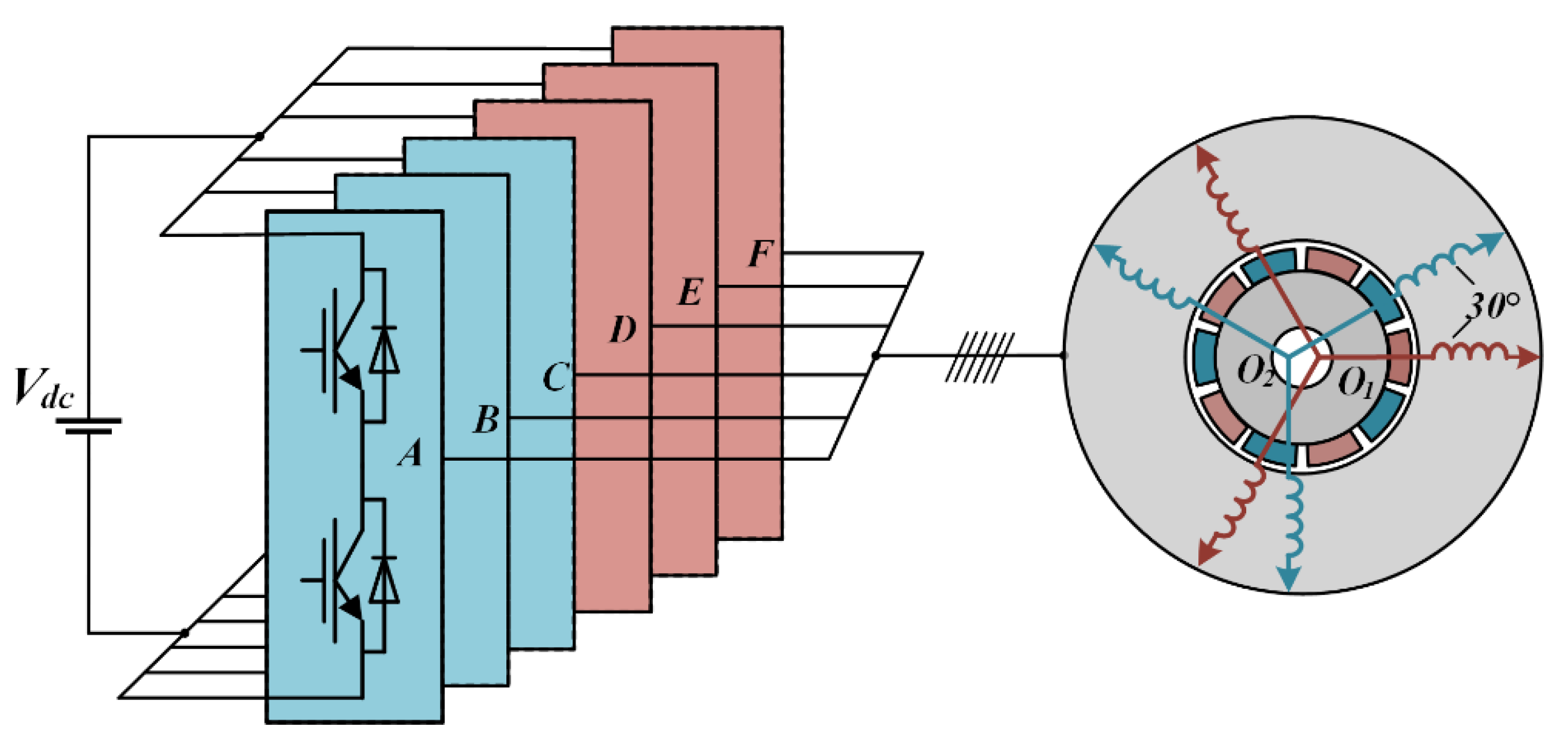
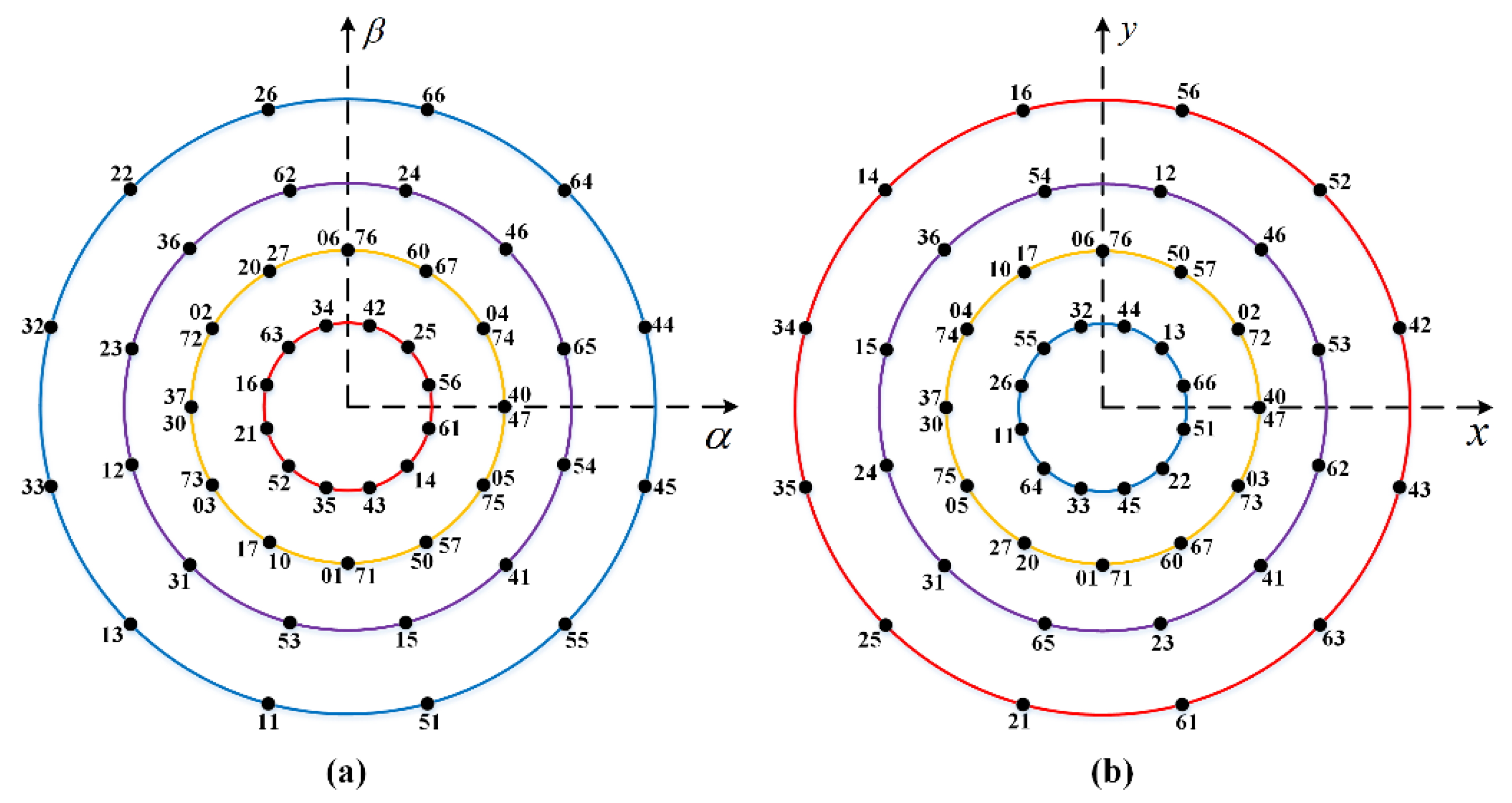
2.1. Dual Three-Phase PMSM Drive

The structure of asymmetrical dual three-phase PMSM studied in this paper is depicted in Figure 1, which has two sets of windings spatially shifted by 30 electrical degrees with two isolated neutral points. A six-phase two-level VSI is applied to power the DTP-PMSM. Considering the nonlinearity and strong coupling characteristics of the motor model, VSD is widely used to decouple the model of DTP-PMSM [18]. As a result, the components in stationary frames are mapped into three decoupled subspaces, namely α-β, x-y, and o1-o2 subspaces. The fundamental and harmonic components in the order of 12k + 1 (k = 1,2,3…) are mapped into the α-β subspace, which takes part in electromechanical energy conversion and generates torque. The harmonics in the order of 6k + 1 (k = 1,3,5…) are mapped into the x-y subspace, which increases copper losses. The o1-o2 subspace represents the zero-sequence harmonic components in the order of 3k (k = 1,3,5…), which are ignored due to the isolation of the neutral point.
Based on the amplitude invariance criterion, the transformation matrix can be expressed as:
[ α β x y o 1 o 2 ] = 1 3 [ 1 1 / 2 1 / 2 3 / 2 3 / 2 0 0 3 / 2 3 / 2 1 / 2 1 / 2 1 1 1 / 2 1 / 2 3 / 2 3 / 2 0 0 3 / 2 3 / 2 1 / 2 1 / 2 1 1 1 1 0 0 0 0 0 0 1 1 1 ] [ A B C D E F ]
Then, the components in the α-β subspace could be transformed into the synchronous frame while the x-y and the o1-o2 subspaces remain in the stationary frame. The transformation matrix from the α-β to d-q subspace is given by:
T = [ cos θ sin θ 0 sin θ cos θ 0 0 0 I 4 ]
By using the coordinate transformation, the model of the DPT-PMSMs in the synchronous frame can be described in (3) and (4), where Rs is the stator resistance, Ld, Lq are inductances of d-axis and q-axis, Lz is the leakage inductance, φf is the permanent magnet flux, and ωe is the rotor angular speed. In addition, denote ud, uq, ux, and uy as the voltages in d-q and x-y subspaces, and id, iq, ix, and iy as the currents in d-q and x-y subspaces.
[ u d u q ] = A [ i d i q ] + B d d t [ i d i q ]   + H [ u x u y ] = R s [ i x i y ] + L z d d t [ i x i y ]
T e = 3 n p ( φ f i q + ( L d L q ) i d i q )
where
A = [ R s ω e L q ω e L d R s ] , B = [ L d 0 0 L q ] , H = [ 0 ω e φ f ] .

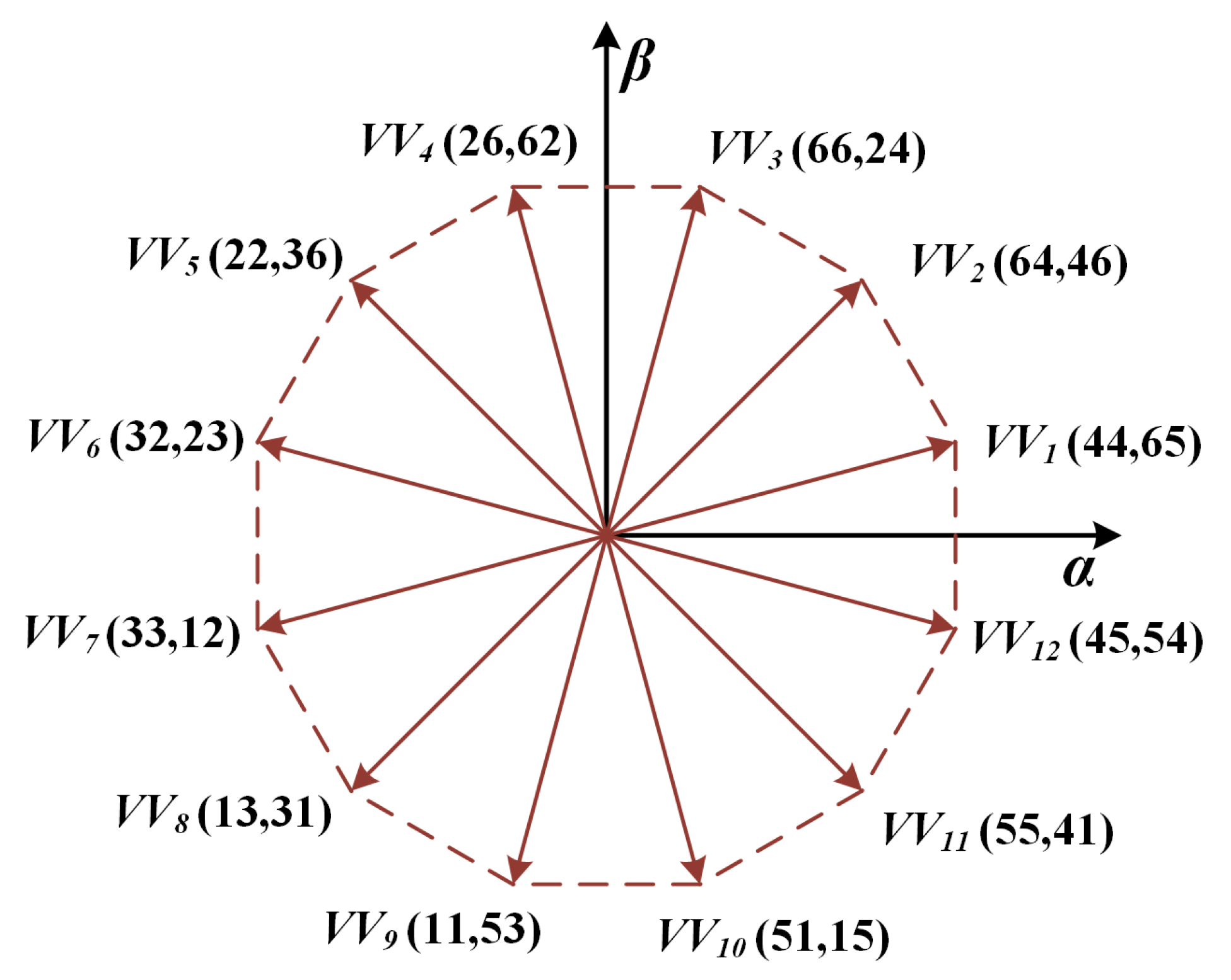
2.2. Virtual Voltage Vector

This motor is powered by a six-phase two-level VSI, which has a total of 26 = 64 different switching states. Each switching state corresponds to a voltage vector in the α-β and the x-y subspaces. Actually, there are a total of 48 vectors in both subspaces due to the redundancy of switch states, just as shown in Figure 2. All vectors could be classified into four groups according to their amplitude, namely the large vectors, the medium-large vectors, the medium vectors, and the small vectors.
The basic idea of the virtual vector is to structure a vector that is active in α-β subspace but the component in x-y subspace is zero. According to Figure 2, it can be observed that the large vectors and medium-large have the same direction in the α-β subspace but opposite in the x-y subspace. Consequently, it is possible to eliminate the current harmonics in the x-y subspace by reasonably distributing the proportion of two vectors. Assuming the control period is Ts, the duration time, T1 and T2, of the large vector and medium-large vector can be calculated by:
{ T 1 × | v l | x y = T 2 × | v m | x y T 1 + T 2 = T s
where the amplitude of large vector and medium-large in the x-y subspace is 0.173 Vdc and 0.471 Vdc, respectively. The results are T1 = 0.732∙Ts and T2 = 0.268∙Ts. Therefore, the virtual vectors can be expressed as:
V V i = 0.732 V l + 0.268 V m
In this way, the virtual vectors without harmonic components are composed of two groups of vectors, just as shown in Figure 3.

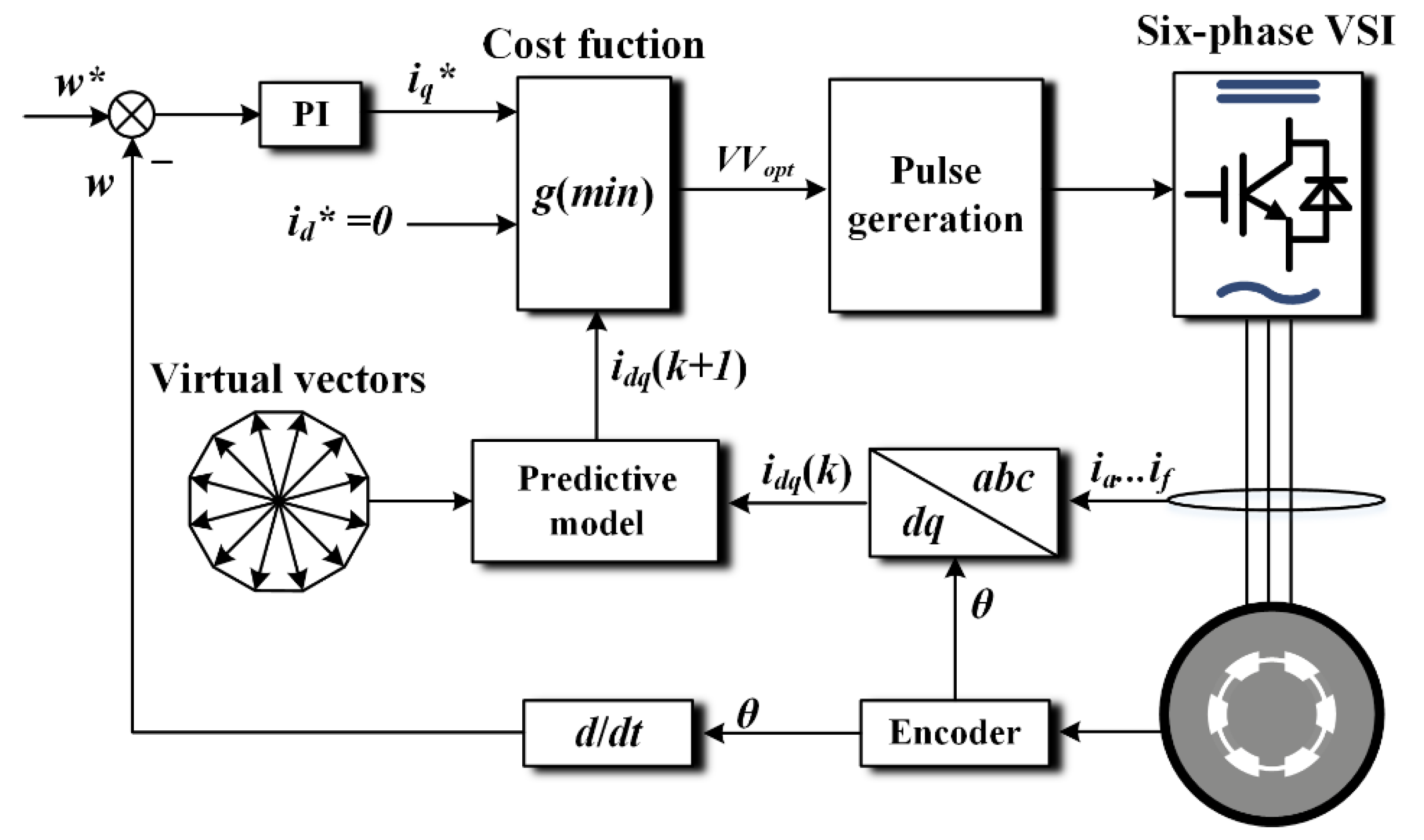
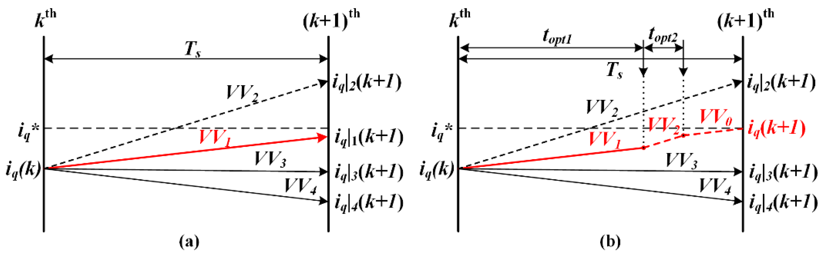
2.3. MPC Based on Virtual Vectors

In model predictive current control, the currents in instant k + 1 can be predicted according to the discretization of (3). Meanwhile, the virtual vectors synthesized above are chosen as alternative vectors. Notably, the prediction of harmonics is no longer needed because the harmonic contents of the x-y subspace are eliminated effectively. Therefore, the current predictive model is expressed by:
{ i d ( k + 1 ) = ( 1 R s L d T s ) i d ( k ) + T s ω e L q L d i q ( k ) + T s L d ( 0.732 u l d + 0.268 u m d ) i q ( k + 1 ) = ( 1 R s L q T s ) i q ( k ) + T s ω e L d L q i d ( k ) T s ω e φ f L q + T s L q ( 0.732 u l q + 0.268 u m q )
where uLd, uLq represent the components of large vectors in the d-axis and q-axis, and uMd, uMq represent the components of medium-large vectors in the d-axis and q-axis. The total control scheme of VV-MPC is described in Figure 4.
Since the harmonic current is eliminated by virtual vectors, the cost function can be simplified so that only dq-axis currents are considered:
g = ( i d * i d ( k + 1 ) ) 2 + ( i q * i q ( k + 1 ) ) 2
After selecting the optimal virtual vector by the cost function, pulse signals are generated by modulation with a fixed duty cycle.

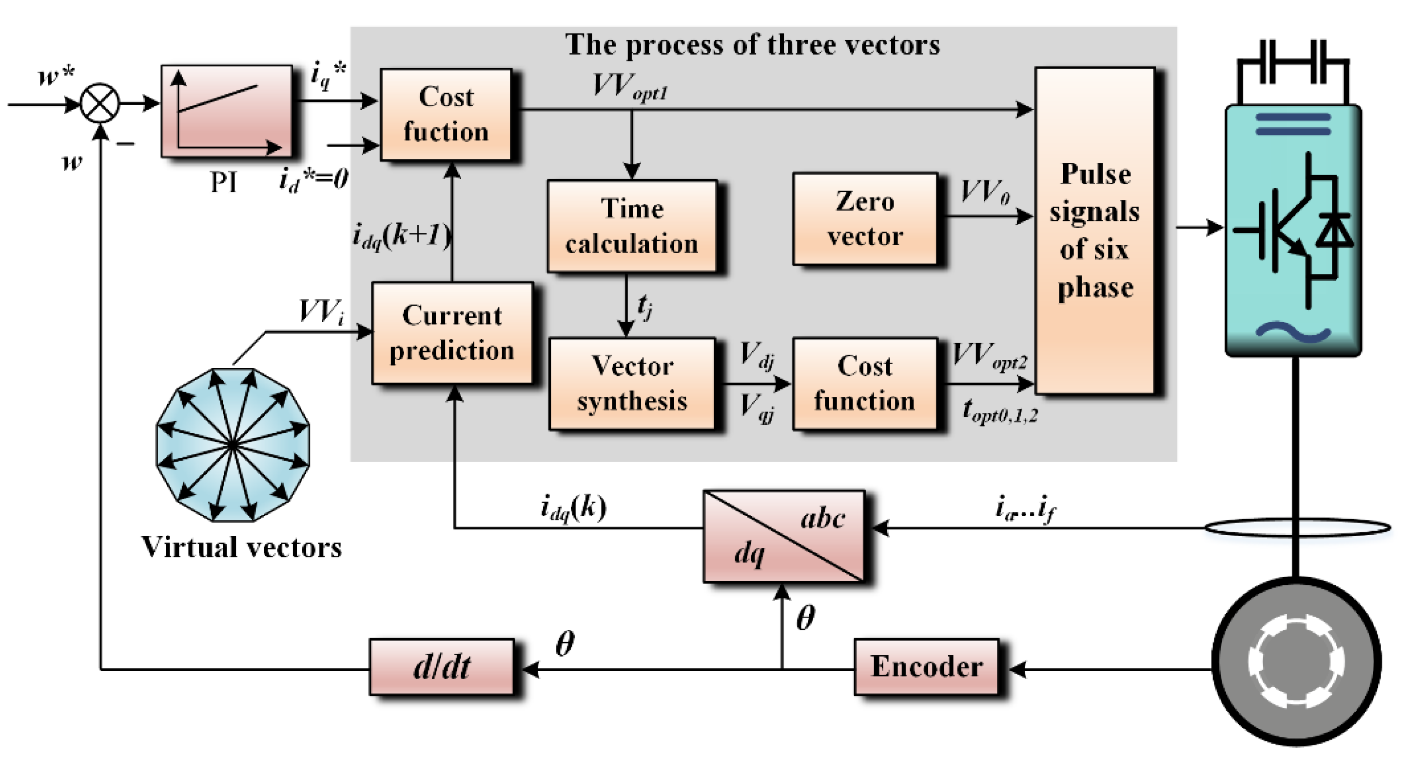
3. Proposed MVV-MPC Scheme

Although the virtual vectors have a good inhibitory effect on harmonic currents, the regulation of current in fundamental subspace is still limited to the cost function. It is this deficiency that affects the accuracy of current tracking. In order to solve this problem, the proposed MVV-MPC adopts two active virtual vectors and a zero vector in one control period. On this basis, the error-free tracking of dq-axis currents could be realized by proper time allocation. In this section, the details of MVV-MPC and its advantages compared with a single virtual vector will be introduced. Figure 5 shows the overall control diagram of the proposed MVV-MPC method.

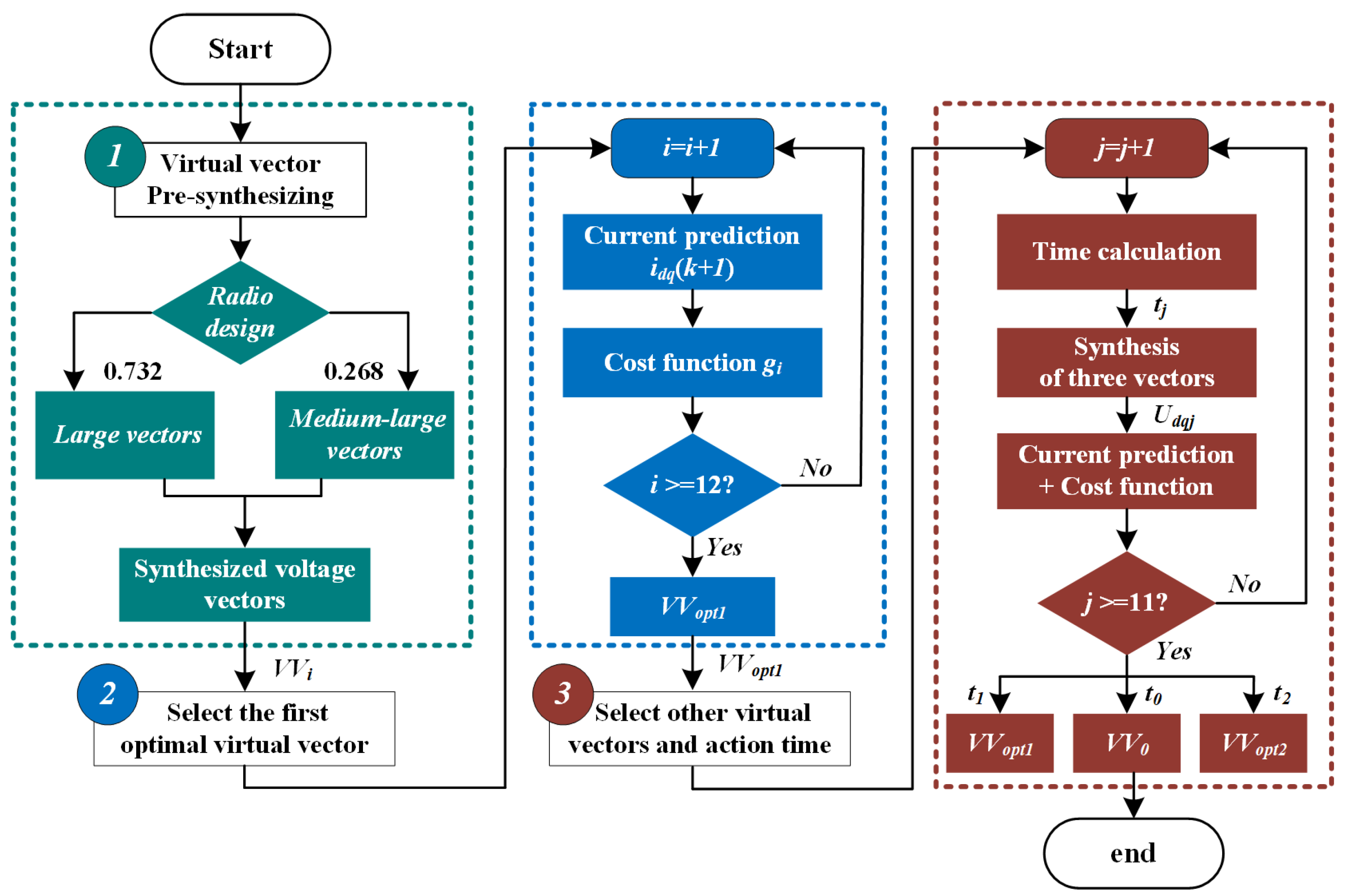
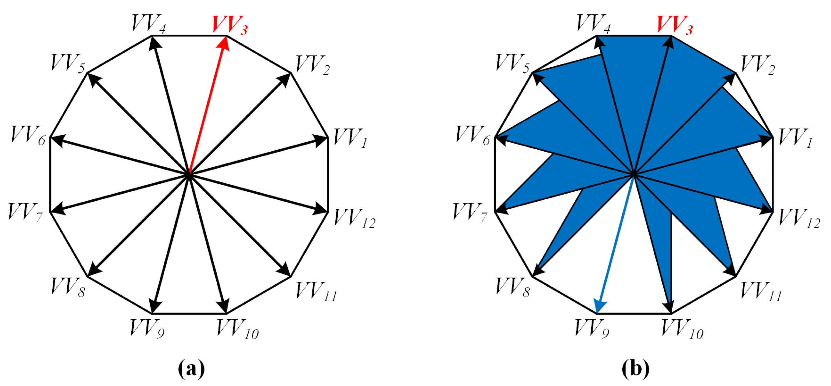
3.1. The Selection of Virtual Vector

In the proposed MVV-MPC scheme, there are three vectors to be selected, including two active virtual vectors and a zero vector. Firstly, an optimal vector VVopt1 is selected as the first virtual vector according to the predictive model (7) and cost function (8), which is the same as with the conventional VV-MPC scheme. On this basis, a second virtual vector VVopt2 should be selected in order to improve the ability of current tracking. For this purpose, the first virtual vector needs to be combined with all the other 11 virtual vectors except itself. The duration time of the two vectors is calculated by deadbeat criteria which will be explained in the next part. Subsequently, the remaining time of a period is supplemented by a zero vector. As a result, a total of 11 combinations can be obtained, and then the optimal combination will be chosen to generate pulse signals.
For a better understanding, the schematic diagram of vector selection is shown in Figure 6. In Figure 6a, the virtual vector that makes the predictive control closer to the given value is chosen as the benchmark. According to appropriate time allocation, the predictive current can reach the given current accurately. Meanwhile, the second virtual vector that causes minimum current ripples is ensured to be selected, which is also the greatest advantage of traversing all combinations.

3.2. The Calculation of Virtual Vector Duration Time

In order to improve the ability of current tracking, the duration time of three vectors is calculated by the deadbeat of dq-axis currents, which can be expressed as:
{ i d ( k + 1 ) = i d ( k ) + k d 0 t 0 + k d 1 t 1 + k d 2 t 2 = i d * i q ( k + 1 ) = i q ( k ) + k q 0 t 0 + k q 1 t 1 + k q 2 t 2 = i q *
where kd0, kq0 represent the current slope of the d-axis and q-axis under zero vector, kd1 and kd2 represent the current slope of the d-axis and q-axis under the first virtual vector, kd2 and kq2 represent the current slope of the d-axis and q-axis under the second virtual vector. In addition, t0, t1, and t2 are the duration time of the three vectors respectively, id* and iq* are the given values of current in the dq-axis.
According to (7), the current slope under different voltage vectors can be expressed as:
{ k d 0 = d i d d t | V V d = 0 = 1 L d ( R s i d + L q ω e i q ) k q 0 = d i q d t | V V q = 0 = 1 L q ( R s i q L d ω e i d ω e φ f )
{ k d 1 = d i d d t | V V d = V V d 1 = k d 0 + V V d 1 L d k q 1 = d i q d t | V V q = V V q 1 = k q 0 + V V q 1 L q
{ k d 2 = d i d d t | V V d = V V d 2 = k d 0 + V V d 2 L d k q 2 = d i q d t | V V q = V V q 2 = k q 0 + V V q 2 L q
where VVd1, VVq1 represent the components of the first virtual vector in the d-axis and q-axis. VVd2 and VVq2 represent the components of the second virtual vector in the d-axis and q-axis. Through (9)–(12), the duration time of vectors could be calculated as:
{ t 1 = 1 N [ ( i q * i q ( k ) ) ( k d 0 k d 2 ) + ( i d * i d ) ( k q 2 k q 0 )      + T s ( k d 2 k q 0 k q 2 k d 0 ) ] t 2 = 1 N [ ( i q * i q ( k ) ) ( k d 1 k d 0 ) + ( i d * i d ) ( k q 0 k q 1 )      + T s ( k q 1 k d 0 k q 0 k d 1 ) ] t 0 = T s T 1 T 2
where N = ( k d 2 k d 1 ) k q 0 + ( k d 0 k d 2 ) k q 1 + ( k d 1 k d 0 ) k q 2 .
It should be noted that the duration time t1 and t2 may not be in the range of 0-Ts. At this moment, it can be divided into two cases:
(1)
When t1 < 0 or t2 < 0, this vector combination will not be adopted.
(2)
When t1 + t2 > Ts, the duration time will be reallocated as:
{ t 1 = t 1 t 1 + t 2 T s t 2 = t 2 t 1 + t 2 T s t 0 = 0
Finally, the components of the synthesized vector on the dq-axis could be acquired by:
{ V V d g = t 1 T s V V d 1 + t 2 T s V V d 2 V V q g = t 1 T s V V q 1 + t 2 T s V V q 2

3.3. The Strategy Analysis of MVV-MPC
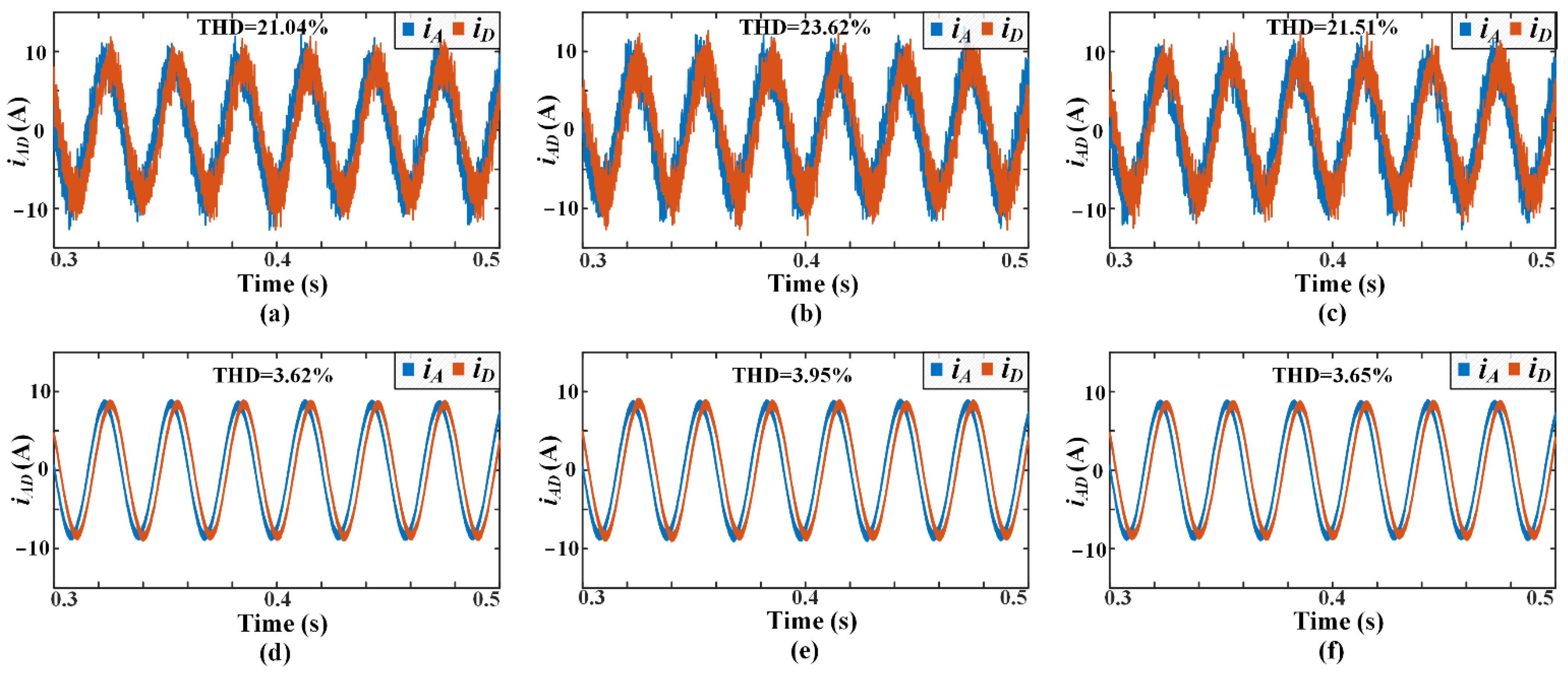
The flowchart of the proposed MVV-MPC is shown in Figure 7, which can be summarized into the following three steps.
Step 1: In this part, a total of 12 alternative virtual vectors are firstly synthesized according to the combination of large vectors and medium-large vectors. In this way, the harmonic component in the x-y subspace is eliminated effectively. Furthermore, any combination of virtual vectors has no influence on the x-y subspace, which is also the foundation of the proposed MVV-MPC.
Step 2: The predictive currents of 12 virtual vectors are calculated and brought into the cost function. The virtual vector which minimizes the cost function will be chosen as the first virtual vector.
Step 3: The other 11 virtual vectors are combined with the first virtual vector, respectively. The duration time of two active virtual vectors is obtained by the principle of deadbeat and the rest time is filled by a zero vector. Subsequently, the optimal vector combination and the corresponding duration time are achieved by traversing the cost function.
Figure 7. Flowchart of proposed MVV-MPC.
Energies 14 07292 g007
It can be seen that the proposed scheme has a total of 23 current predictions in a control period. Compared with conventional VV-MPC, although the number of predictions has increased, enhanced dq-axis current tracking is obtained because the amplitude and phase angle of the output voltage vector are adjustable.
Assuming the VV3 is the first virtual vector, the coverage of the output voltage vector is shown in Figure 8b. Compared with the traditional VV-MPC where both amplitude and phase angle are fixed, the coverage in the proposed MVV-MPC has significant improvement. Therefore, the current ripple is effectively reduced so that a better control performance is acquired in the proposed method.

4. Results

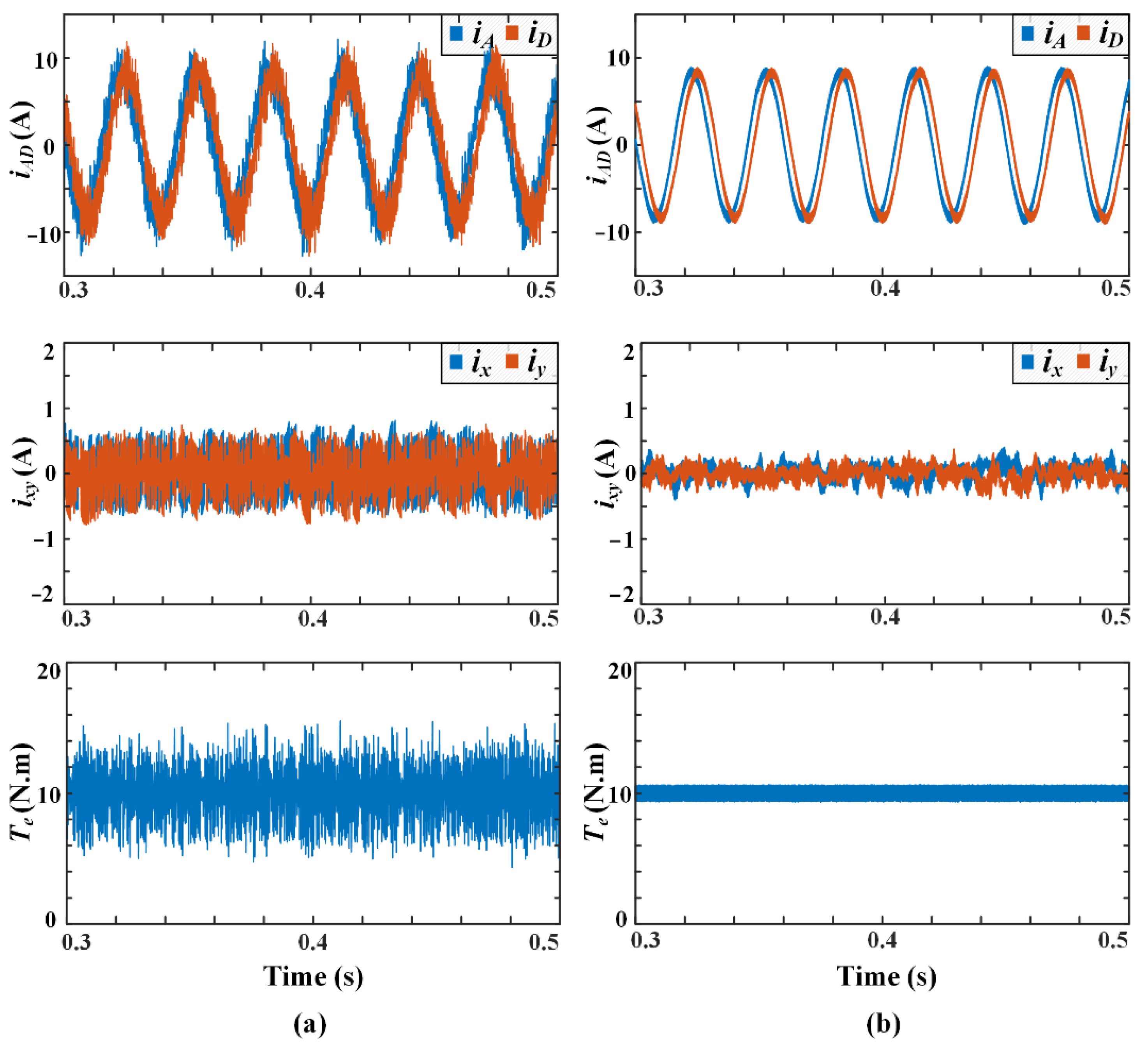
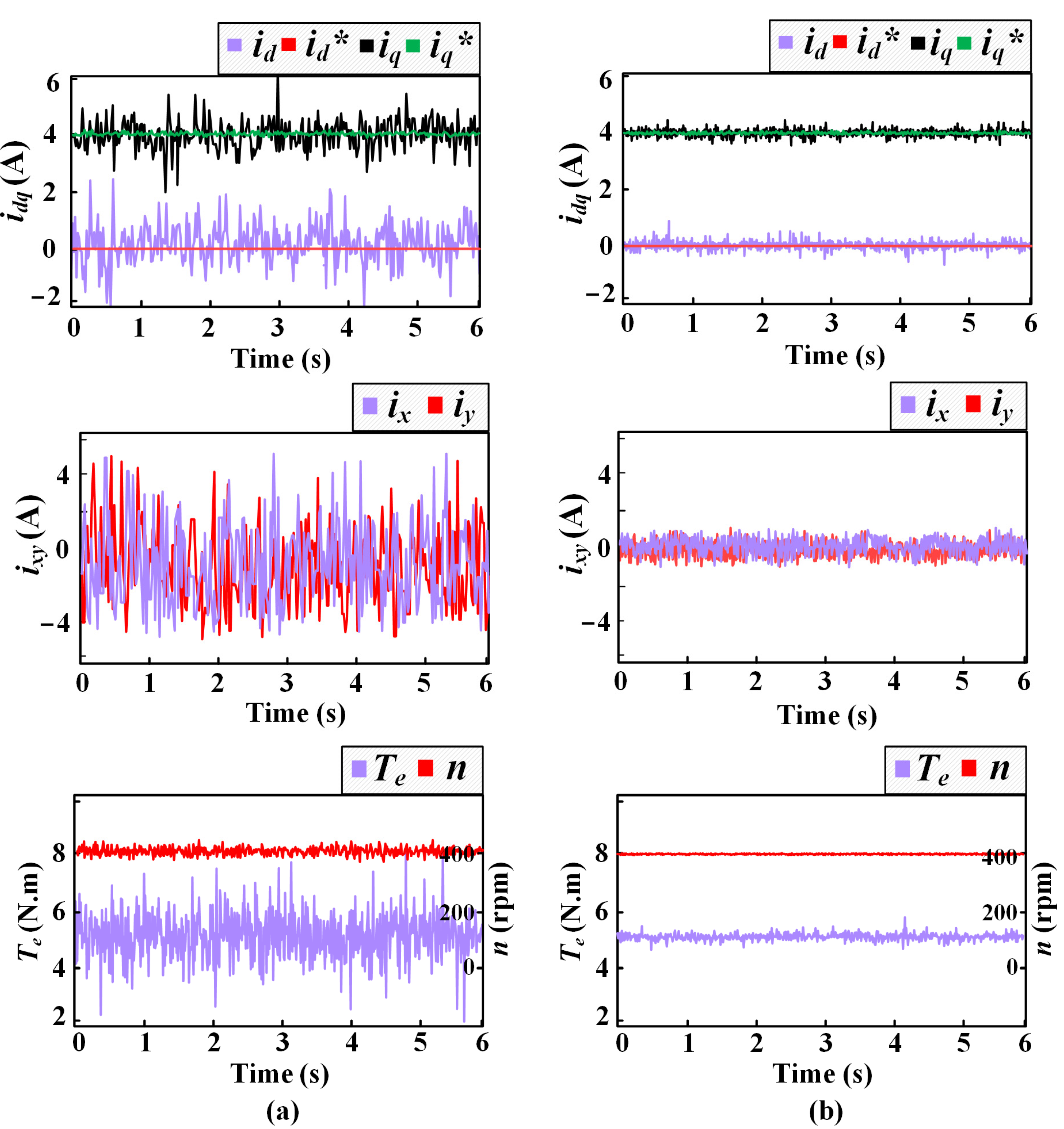
4.1. Simulated Results

In this section, the simulated results are carried out to verify the feasibility of the proposed MVV-MPC scheme in the environment of MATLAB/SIMULINK. Additionally, conventional virtual-vector-based MPC is also implemented as a benchmark method. The virtual vectors applied in two methods are both synthesized by large vectors and medium-large vectors. The key parameters of DTP-PMSM are listed in Table 1. The given speed is set as 400 rpm for both methods in the simulation.
Firstly, the steady-state performance of DTP-PMSM is investigated at 400 rpm with a 10 N.m load. An intuitive comparison between conventional VV-MPC and proposed MVV-MPC is shown in Figure 9. It can be seen from Figure 9a that the current quality in conventional VV-MPC is much poorer than that in the proposed method. This can be explained by the fact that conventional VV-MPC is lacking the regulation of current in fundamental subspace. In contrast, a deadbeat prediction is realized in the proposed method, which is also reflected in phase current quality. In terms of the current in the x-y subspace, a relatively smaller amplitude is acquired in the proposed MVV-MPC although both methods have a good harmonic suppression effect due to the application of virtual vector. In the meantime, the enhancement of steady-state performance is more directly embodied in electromagnetic torque. The torque ripple of the proposed MVV-MPC is limited within the range of ± 0.5 N.m while the ripple is increased to 5 N.m in conventional VV-MPC. Thus, the proposed method has an apparent improvement in steady-state performance. The waveform comparison of phase current and torque is presented in Figure 10.
Secondly, a test with a sudden load change is also investigated to illustrate the dynamic response. The machine is initially operated under 5 N.m load and then the load is changed to 10 N.m at t = 0.3 s. It can be seen that both current and torque are tracked quickly and smoothly. Meanwhile, the performance of current quality and torque ripple are consistent with that in a steady-state test. To sum up, the proposed MVV-MPC offers a significant improvement of steady-state performance without affecting its dynamic characteristics.
Figure 9. Steady-state performance with a load of 10 N.m. (a) Conventional VV-MPC; (b) proposed MVV-MPC.
Energies 14 07292 g009
Figure 10. Steady-state performance with a load of 10 N.m. (a) Conventional VV-MPC; (b) proposed MVV-MPC.
Energies 14 07292 g010
In order to verify the parameter dependence of the proposed MVV-MPC scheme, a comparison of both methods with parameter mismatch is presented in Figure 11. Two different cases are included in this test, namely the motor inductance is 10% lower than MPC implementation and motor resistance is 10% higher. The simulated results show that the current harmonic is increased slightly with the mismatch of parameters, while the change of waveform is not significant. Compared with the two parameters, the resistance value presents little impact on the performance for both methods. It can be explained that the value of RsTs in Equation (7) is too small so that the change of resistance could be ignored. Besides, a smaller variation of THD indicates that the proposed MVV-MPC is less parameter-dependent than the VV-MPC. Finally, it can be concluded that MVV-MPC provides better parameter robustness although the influence of parameter mismatch is not obvious for the two methods.

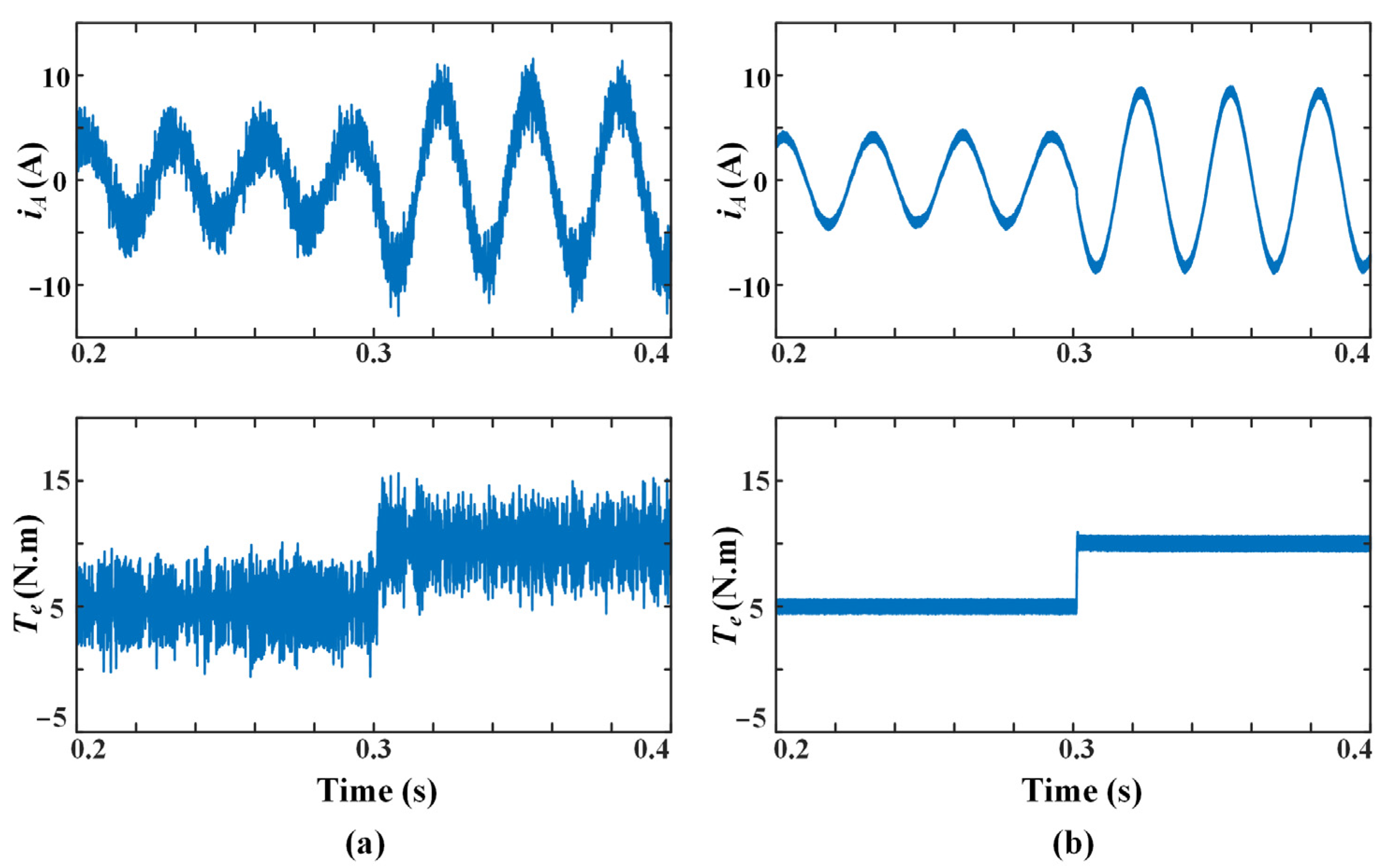
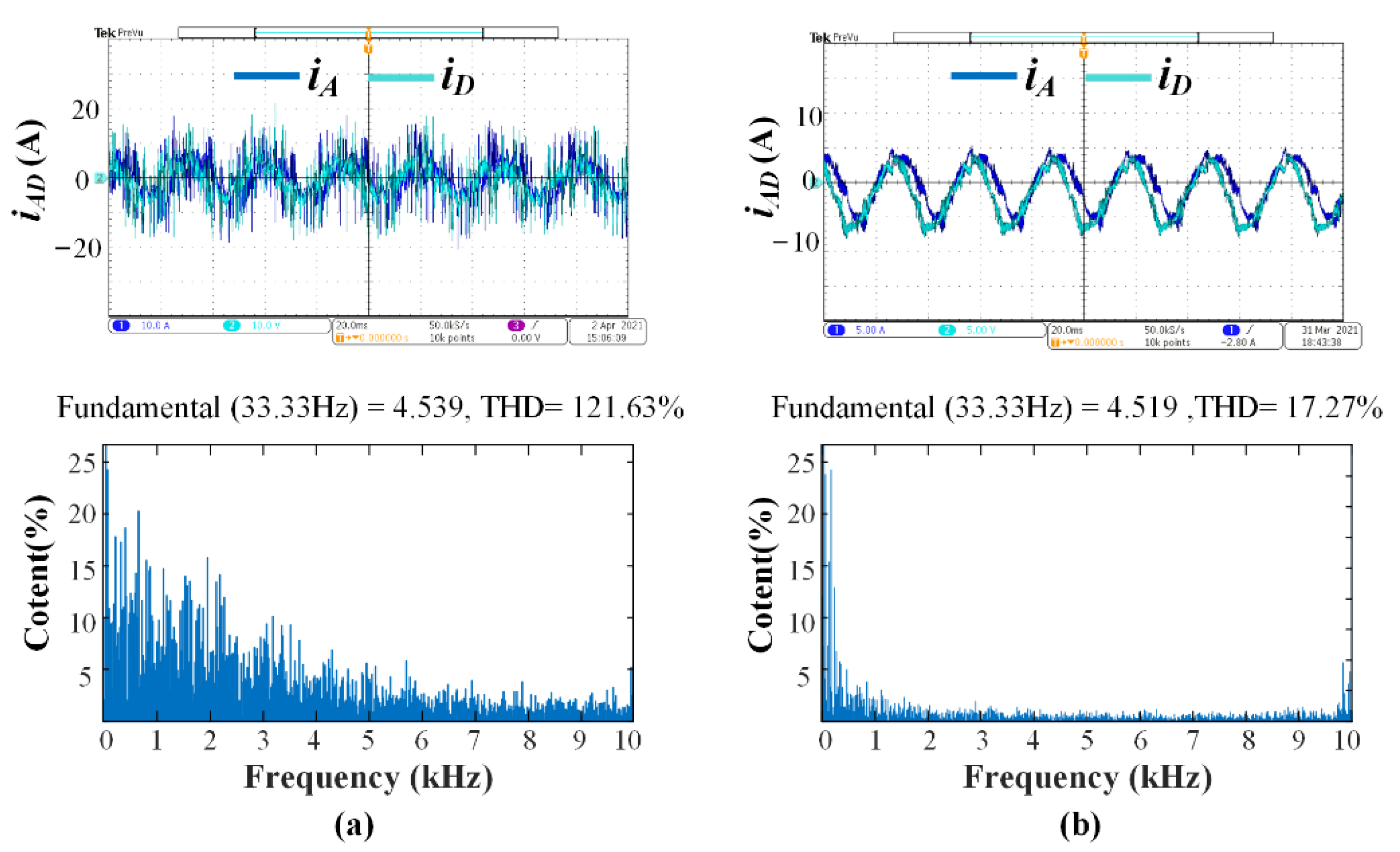
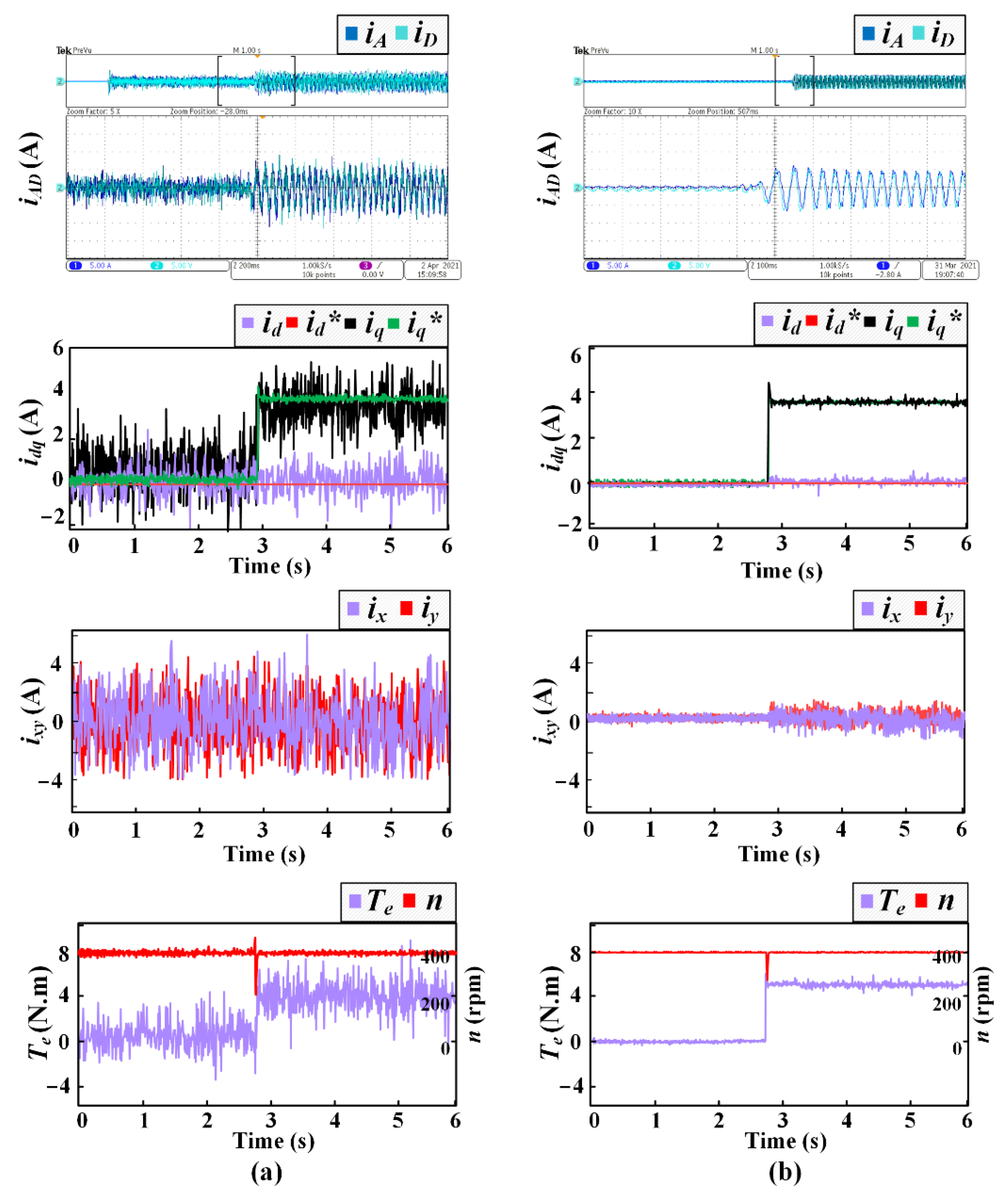
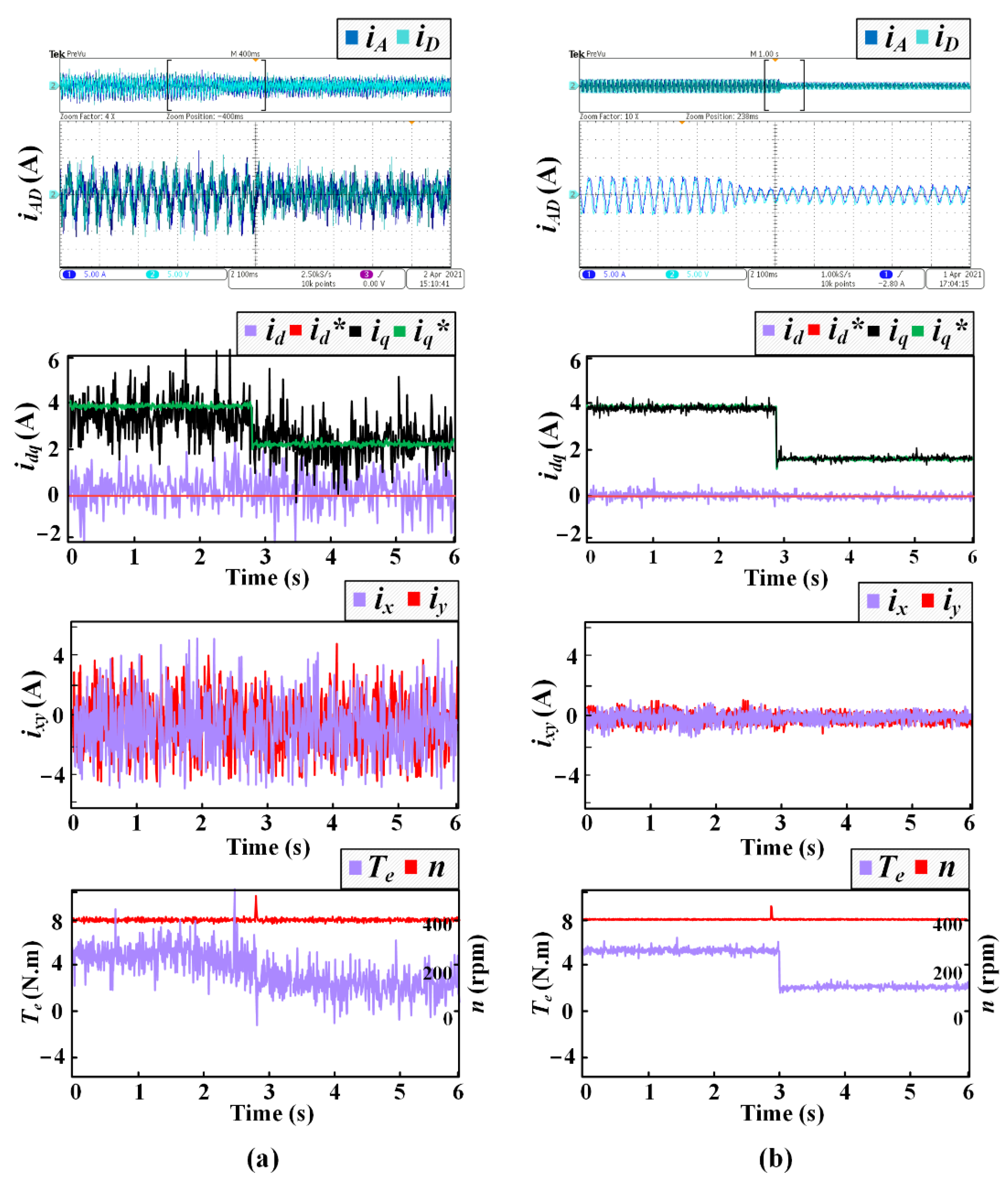
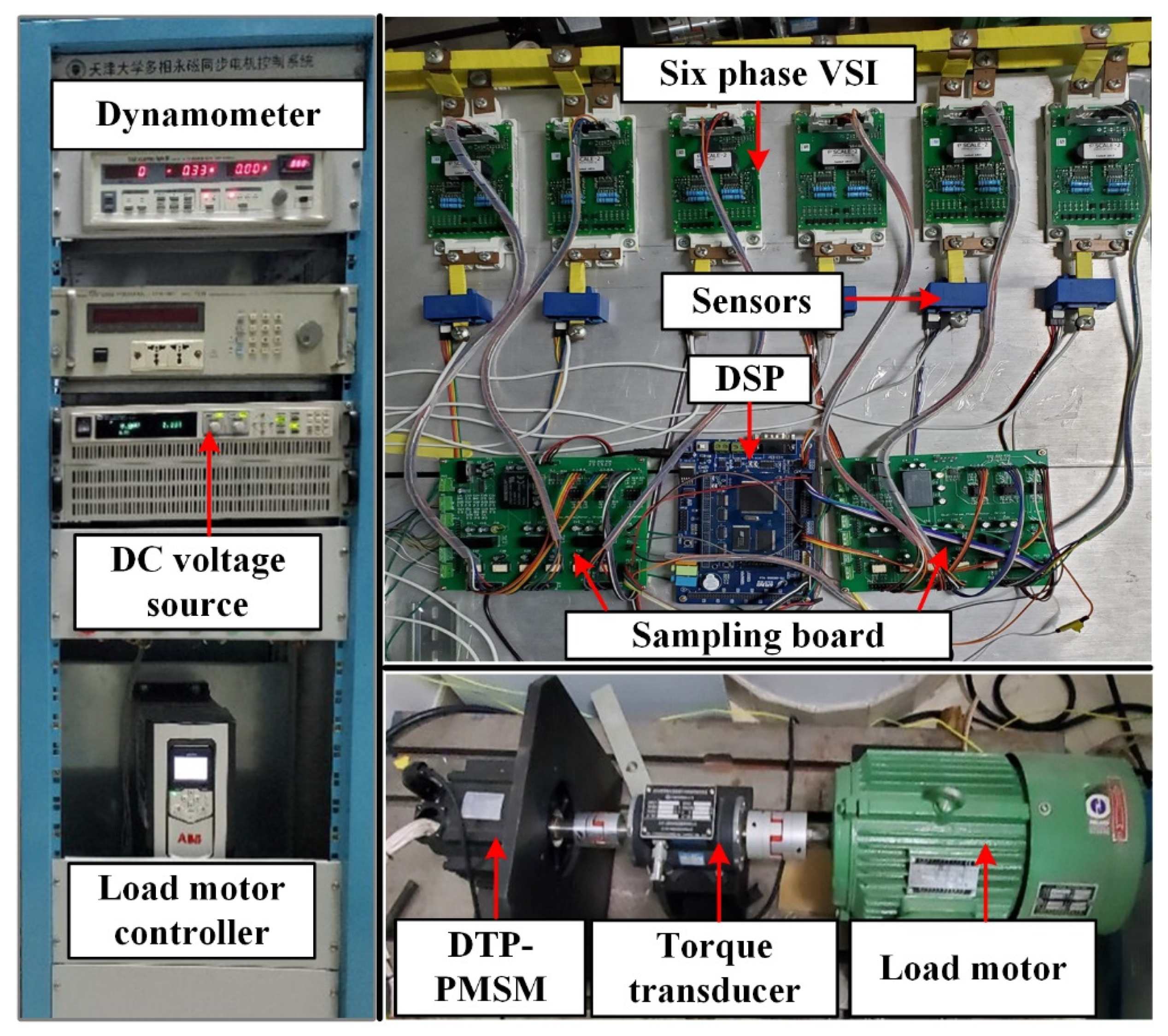
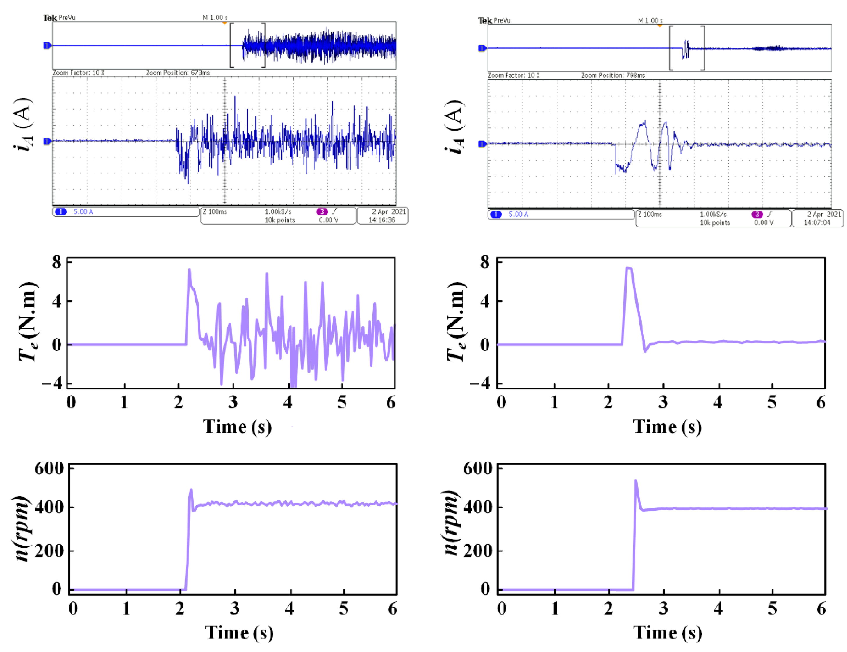
4.2. Experimental Results

In order to experimentally verify the feasibility of the proposed MVV-MPC scheme for the machine drive system, a prototype is established based on a DTP-PMSM as shown in Figure 12 and their models are listed in Table 2. The corresponding parameters are the same as those for the simulation listed in Table 1. The exemplified DTP-PMSM is driven by a six-phase two-level voltage source inverter and the control signals are generated by a digital signal processor (TMS320F28335). A three-phase induction motor controlled by an ABB servo is utilized as a load motor. The bus voltage is provided by a DC voltage source. The six phase currents are measured by current sensors. All waveforms are measured by using the oscilloscope (Tektronix/MDO3024) and LABVIEW. In the experimental verification, this paper carries out four independent tests from the perspective of the steady-state, transient-state, and acceleration state. The reference speed and sampling frequency are set as 400 rpm and 10 kHz for all tests. Moreover, the velocity PI controller parameters are set as kp = 0.02 and ki = 0.002.
A comparison between VV-MPC and MVV-MPC is shown in Figure 13 to investigate the steady-state performance with the load of 5 N.m. The contrast waveforms include d-q currents, x-y currents, torque, and speed. It can be noted that the d-q currents ripple in the proposed MVV-MPC is evidently reduced although they can be stable near the reference value in both methods. One of the reasons for poor d-q current tracking ability in conventional VV-MPC is that the d-q currents are regulated only by the cost function. Certainly, a relatively larger prediction error emerges in this method. Another reason could be that the low inductance (Ld, Lq) affects the current quality to a great extent. In terms of DTP-PMSM with low inductance, the current suppression ability is so poor that a small voltage acting on the inductance will generate a large current variation. Accordingly, the large current ripple is inevitable when a single virtual vector is applied to the whole control period. By comparison, the two issues mentioned above are well addressed in the proposed MVV-MPC by means of the interaction of multiple virtual vectors, just as shown in Figure 13b. Furthermore, the reduction of d-q current ripple means a better torque performance, which directly influences the performance of the motor drive system. Thus, a more stable speed is obtained in the proposed method through the suppression of torque ripple. In addition, the MVV-MPC scheme is also helpful to reduce x-y currents. Finally, the collective improvement in α-β and x-y subspace brings out a much better phase current. In Figure 14, the frequency spectrum of phase current is conducted within the range from 0 to 10 kHz. It can be noticed that the total harmonic distortion (THD) in conventional VV-MPC is 121.63%, while it is sharply decreased to 17.27% in MVV-MPC. As a result, a phase current with a smooth sinuous curve is received in MVV-MPC. In the meantime, the rms values of the two methods at fundamental frequency are 4.539 A and 4.519 A, respectively. This also implies that the copper losses can be effectively reduced in the proposed MVV-MPC.
Additionally, the dynamic response is also carried out to investigate the control performance of the proposed MVV-MPC. The waveforms of dynamic response are plotted in Figure 15, including phase currents, d-q currents, x-y currents, torque, and speed. In the beginning, the motor is performing at 400 rpm without load and then a 5 N.m load is added suddenly. A quick dynamic response could be observed for both methods. However, the current ripple is large in conventional VV-MPC, which also leads to a worsening torque response. In contrast, a smooth transition and short tracking time can be offered by using the proposed MVV-MPC. What is more, the speed owes a smaller fluctuation and can quickly return to the reference value after a load increased. It should be highlighted that the x-y currents will increase with the sudden increase of load. Fortunately, the amplitude of x-y currents in MVV-MPC is still far less than that in conventional VV-MPC. Additionally, a test of dynamic response under the load from 5 N to 2 N is also given in Figure 16. It illustrates that the proposed scheme has a satisfying dynamic tracking performance in the case of a sudden load drop. Tests in both cases indicate that the proposed MVV-MPC can improve the steady-state performance without affecting the dynamic response.
Figure 13. Test 1 for both methods in steady-state with 5 N.m load. (a) Conventional VV-MPC; (b) proposed MVV-MPC.
Energies 14 07292 g013
Figure 14. FFT analysis of phase current for both methods with 5N.m load. (a) Conventional VV-MPC; (b) proposed MVV-MPC.
Energies 14 07292 g014
Figure 15. Test 2 for both methods with a sudden load increase. (a) Conventional VV-MPC; (b) proposed MVV-MPC.
Energies 14 07292 g015
Figure 16. Test 3 for both methods with a sudden load decrease. (a) Conventional VV-MPC; (b) proposed MVV-MPC.
Energies 14 07292 g016
Moreover, a test that examines the acceleration performance is investigated in Figure 17, where the motor accelerates from standstill to 400 rpm without load. The waveforms of phase current, torque, and speed are given in this test. In the proposed MVV-MPC, the reference speed is quickly reached after an overshoot, the phase current and torque reach a steady state at the end of the acceleration process. In addition, the quality of current, torque, and speed in MVV-MPC provides a significant improvement, which is constant with the test in steady-state performance.
To sum up, the deficiency of regulation in fundamental subspace results in poorer control performance, which will be further aggravated due to the influence of low inductance. However, the proposed MVV-MPV shows a much better performance in both steady-state and dynamic processes. Therefore, the feasibility of MVV-MPC is verified through the test in various situations.

5. Conclusions

The traditional MPC scheme suffers from a high current and torque ripple. Meanwhile, the characteristic of DTP-PMSM introduces additional x-y currents which need to be suppressed. In order to deal with the aforementioned issues, the main contributions of this paper are as follows:
(1)
The virtual vectors are pre-synthesized by large vectors and medium-large vectors, which aim to eliminate the components in harmonic subspace.
(2)
Two active virtual vectors and a zero vector are applied in this method according to the principle of deadbeat, thus the currents in fundamental subspace are also well regulated.
(3)
Through two traversals of the virtual vector, the optimal combination that ensures a minimum cost function could be selected.
Therefore, the multi-virtual-vector model predictive control is proposed in this paper based on the above work. The proposed MVV-MPC scheme provides better steady-state performance while ensuring dynamic performance.
Although the effectiveness of MVV-MPC is verified by simulated and experimental results, there are still aspects that need to be improved in future work. For example, the MVV-MPC scheme results in higher computational complexity due to the increase of the number of voltage vectors and the number of loops. Therefore, a future study will concentrate on the simplification of calculation.

Author Contributions

Conceptualization, Z.W. and Z.Z. (Zhen Zhang); methodology, Z.W.; software, Z.W. and Q.L.; validation, Z.W. and Z.Z. (Zhen Zhang); writing—original draft preparation, Z.W. and T.L.; writing—review and editing, Z.Z. (Zhihao Zhu), Y.L. and C.L. All authors have read and agreed to the published version of the manuscript.

Funding

This work was supported by the National Natural Science Foundation of China under Project 51977138.

Institutional Review Board Statement

Not applicable.

Informed Consent Statement

Not applicable.

Data Availability Statement

Not applicable.

Conflicts of Interest

The authors declare no conflict of interest.

References

  1. Tu, W.; Luo, G.; Chen, Z.; Cui, L.; Kennel, R. Predictive cascaded speed and current control for PMSM drives with multi-timescale Optimization. IEEE Trans. Power Electron. 2019, 34, 11046–11061. [Google Scholar] [CrossRef]
  2. Kakosimos, P.; Abu-Rub, H. Predictive speed control with short prediction horizon for permanent magnet synchronous motor drives. IEEE Trans. Power Electron. 2018, 33, 2740–2750. [Google Scholar] [CrossRef]
  3. Luo, G.; Zhang, R.; Chen, Z.; Tu, W.; Zhang, S.; Kennel, R. A novel nonlinear modeling method for permanent-magnet synchronous motors. IEEE Trans. Ind. Electron. 2016, 63, 6490–6498. [Google Scholar] [CrossRef]
  4. Zhang, X.; Zhang, L.; Zhang, Y. Model predictive current control for PMSM drives with parameter robustness improvement. IEEE Trans. Power Electron. 2019, 34, 1645–1657. [Google Scholar] [CrossRef]
  5. Mariethoz, S.; Morari, M. Explicit model-predictive control of a PWM inverter with an LCL filter. IEEE Trans. Ind. Electron. 2009, 56, 389–399. [Google Scholar] [CrossRef]
  6. Casadei, D.; Profumo, F.; Serra, G.; Tani, A. FOC and DTC: Two viable schemes for induction motors torque control. IEEE Trans. Power Electron. 2002, 17, 779–787. [Google Scholar] [CrossRef] [Green Version]
  7. Holtz, J. Advanced PWM and predictive control—An overview. IEEE Trans. Ind. Electron. 2016, 63, 3837–3844. [Google Scholar] [CrossRef]
  8. Nguyen, H.T.; Jung, J. Finite control set model predictive control to guarantee stability and robustness for surface-mounted PM synchronous motors. IEEE Trans. Ind. Electron. 2018, 65, 8510–8519. [Google Scholar] [CrossRef]
  9. Zhang, Y.; Yang, H. Model predictive torque control of induction motor drives with optimal duty cycle control. IEEE Trans. Power Electron. 2014, 29, 6593–6603. [Google Scholar] [CrossRef]
  10. Davari, S.A.; Khaburi, D.A.; Kennel, R. An improved FCS–MPC algorithm for an induction motor with an imposed optimized weighting factor. IEEE Trans. Power Electron. 2012, 27, 1540–1551. [Google Scholar] [CrossRef]
  11. Zhang, Y.; Yang, H. Torque ripple reduction of model predictive torque control of induction motor drives. In Proceedings of the IEEE Energy Conversion Congress and Exposition, Denver, CO, USA, 15–19 September 2013; pp. 1176–1183. [Google Scholar]
  12. Zhang, Y.; Yang, H. Generalized two-vector-based model-predictive torque control of induction motor drives. IEEE Trans. Power Electron. 2015, 30, 3818–3829. [Google Scholar] [CrossRef]
  13. Zhang, Y.; Yang, H. Two-vector-based model predictive torque control without weighting factors for induction motor drives. IEEE Trans. Power Electron. 2016, 31, 1381–1390. [Google Scholar] [CrossRef]
  14. Zhang, Y.; Peng, Y.; Yang, H. Performance improvement of two-vectors-based model predictive control of PWM rectifier. IEEE Trans. Power Electron. 2016, 31, 6016–6030. [Google Scholar] [CrossRef]
  15. Kang, S.; Soh, J.; Kim, R. Symmetrical three-vector-based model predictive control with deadbeat solution for IPMSM in rotating reference frame. IEEE Trans. Ind. Electron. 2020, 67, 159–168. [Google Scholar] [CrossRef]
  16. Zhao, Y.; Lipo, T. Space vector PWM control of dual three-phase induction machine using vector space decomposition. IEEE Trans. Ind. Appl. 1995, 31, 1100–1109. [Google Scholar] [CrossRef]
  17. Xu, Z.; Wang, Z.; Wang, X.; Cheng, M. Predictive current control method for dual three-phase PMSM drives with reduced switching frequency and low-computation burden. IET Electr. Power Appl. 2020, 14, 668–677. [Google Scholar] [CrossRef]
  18. Duran, M.J.; Prieto, J.; Barrero, F.; Toral, S. Predictive current control of dual three-phase drives using restrained search techniques. IEEE Trans. Ind. Electron. 2011, 58, 3253–3263. [Google Scholar] [CrossRef]
  19. Xue, C.; Song, W.; Feng, X. Finite control-set model predictive current control of five-phase permanent-magnet synchronous machine based on virtual voltage vectors. IET Electr. Power Appl. 2017, 11, 836–846. [Google Scholar] [CrossRef]
  20. Gonzalez-Prieto, I.; Duran, M.J.; Aciego, J.J.; Martin, C.; Barrero, F. Model predictive control of six-phase induction motor drives using virtual voltage vectors. IEEE Trans. Ind. Electron. 2018, 65, 27–37. [Google Scholar] [CrossRef]
  21. Luo, Y.; Liu, C. Elimination of harmonic currents using a reference voltage vector based-model predictive control for a six-phase PMSM motor. IEEE Trans. Power Electron. 2019, 34, 6960–6972. [Google Scholar] [CrossRef]
  22. Aciego, J.J.; Prieto, I.G.; Duran, M.J. Model predictive control of six-phase induction motor drives using two virtual voltage vectors. IEEE J. Emerg. Sel. Top. Power Electron. 2019, 7, 321–330. [Google Scholar] [CrossRef]
Figure 1. Scheme of the dual three-phase PMSM drive.
Energies 14 07292 g001
Figure 2. Voltage vectors in two subspaces. (a) α-β; (b) x-y.
Energies 14 07292 g002
Figure 3. Virtual voltage vectors in the α-β subspace.
Energies 14 07292 g003
Figure 4. Control scheme of VV-MPC.
Energies 14 07292 g004
Figure 5. Control scheme of VV-MPC.
Energies 14 07292 g005
Figure 6. Virtual vector selection of MVV-MPC. (a) The selection of the first virtual vector; (b) the selection of the second vector and zero vector.
Energies 14 07292 g006
Figure 8. The range of output voltage vector for two methods. (a) VV-MPC, (b) proposed MVV-MPC.
Energies 14 07292 g008
Figure 11. Simulation results of both methods with parameter mismatch. (a) VV-MPC without mismatch; (b) VV-MPC with 10% inductance mismatch; (c) VV-MPC with 10% resistance mismatch; (d) MVV-MPC without mismatch; (e) MVV-MPC with 10% inductance mismatch; (f) MVV-MPC with 10% resistance mismatch.
Energies 14 07292 g011
Figure 12. Experimental prototype.
Energies 14 07292 g012
Figure 17. Test 4 for both methods at acceleration state without load. (a) Conventional VV-MPC; (b) proposed MVV-MPC.
Energies 14 07292 g017
Table 1. Key parameters of the experimental prototype.
ItemValue
Stator resistance (R)0.45 Ω
Inductance of d-axis (Ld)1.4 mH
Inductance of q-axis (Lq)1.4 mH
Leakage inductance (Lxy)1.1 mH
Permanent magnet flux (ψ)0.08 wb
Numbers of pole pairs (P)5
Rotational inertia (J)0.0023 kg·m2
DC bus voltage (Vdc)100 V
Rated speed (n)2000 rpm
Rated torque (T)10 N.m
Sample frequency (f)10 kHz
Table 2. Experimental configurations.
EquipmentType
Current sensorsHAS-50S
DC powerIT6535C
VSIFF300R12ME4
Drive board of VSI2SP0115T2C0-12
Publisher’s Note: MDPI stays neutral with regard to jurisdictional claims in published maps and institutional affiliations.

