
Artificial Negative Polarity Thunderstorm Cell Modeling of Nearby Incomplete Upward Discharges’ Influence on Elements of Monitoring Systems for Air Transmission Lines

 ,
,
Abstract
:1. Introduction
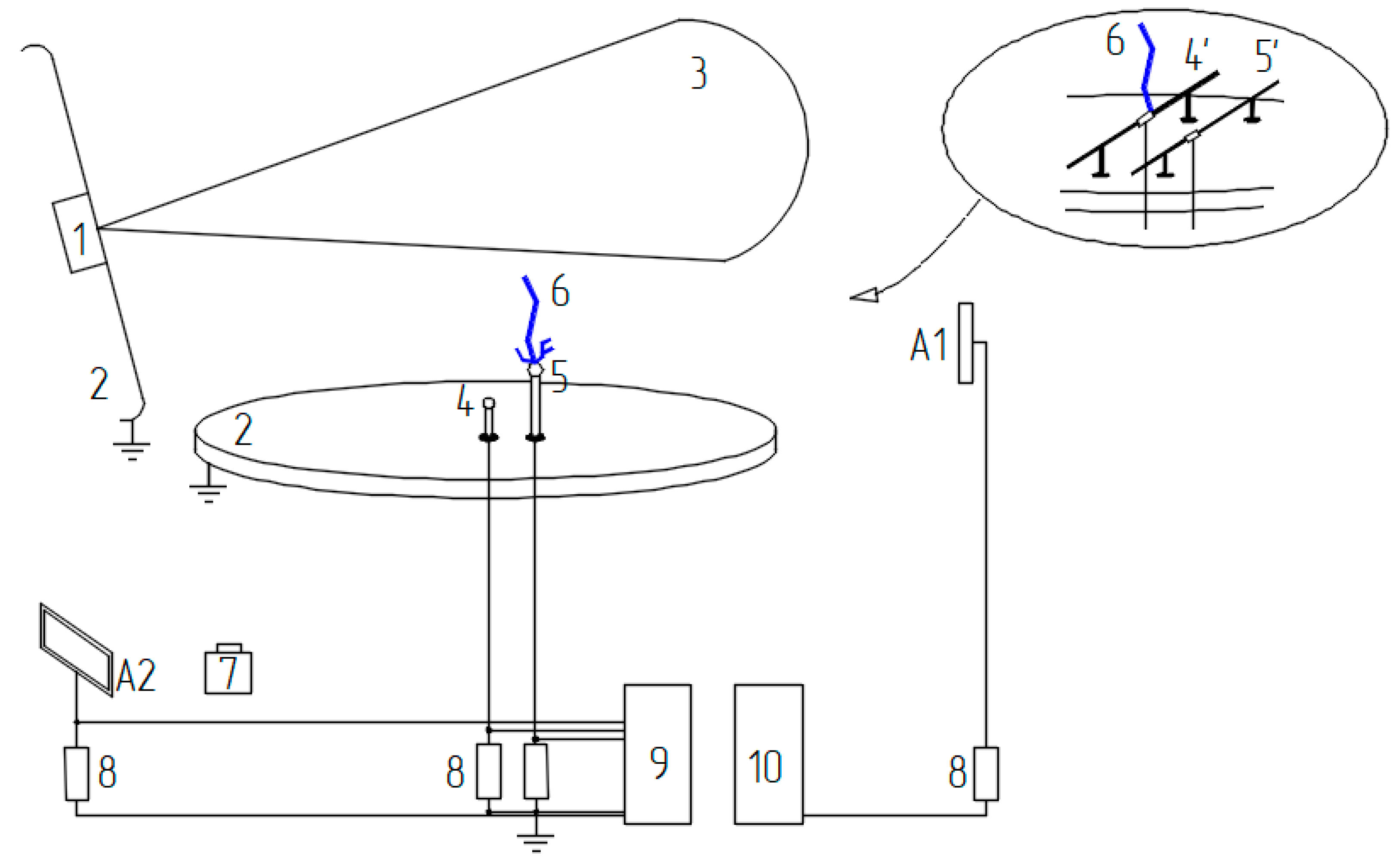
2. Experimental Complex and Experiment Schemes
- (1)
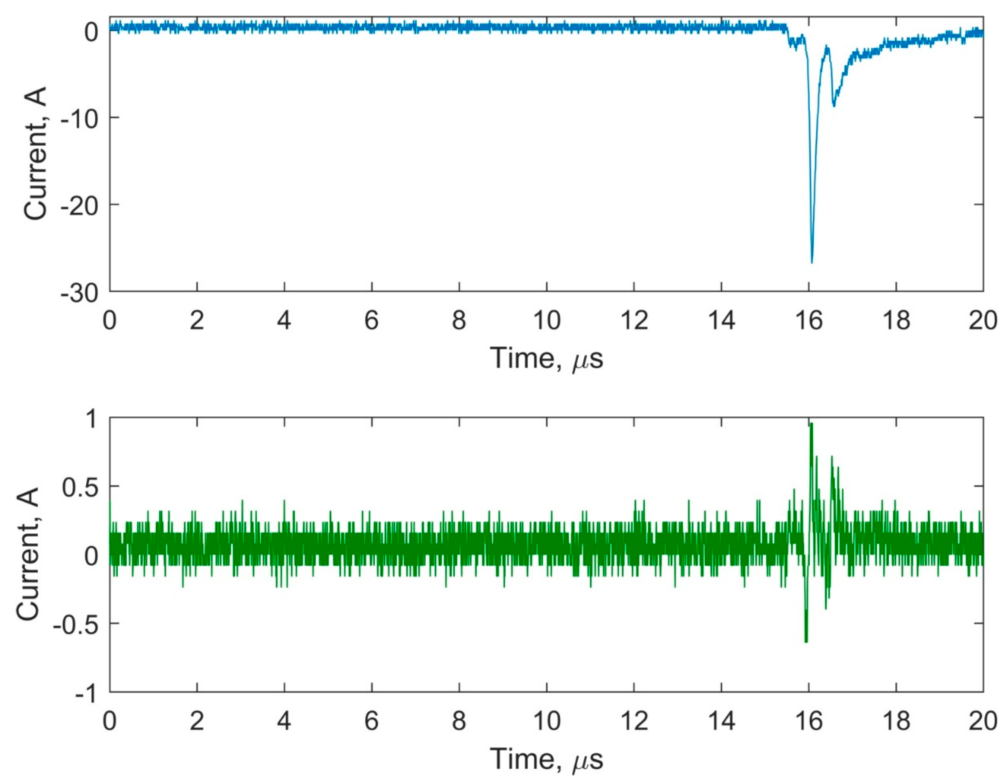
- Discharge current initiated at the ground model elements,
- (2)
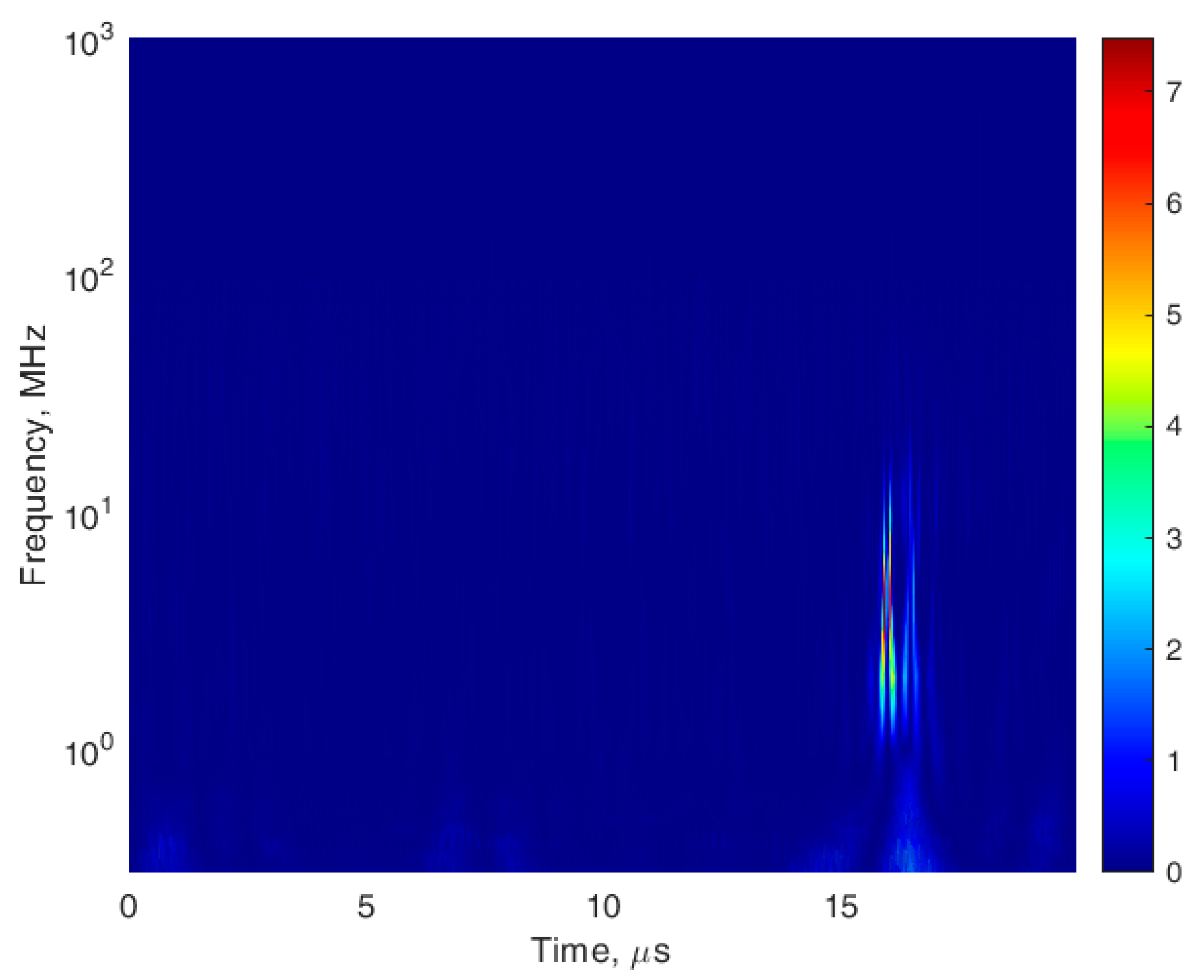
- Electric induction current inflicted by discharge phenomena on the nearest models of digital objects and systems (sensors and antennas).
- -
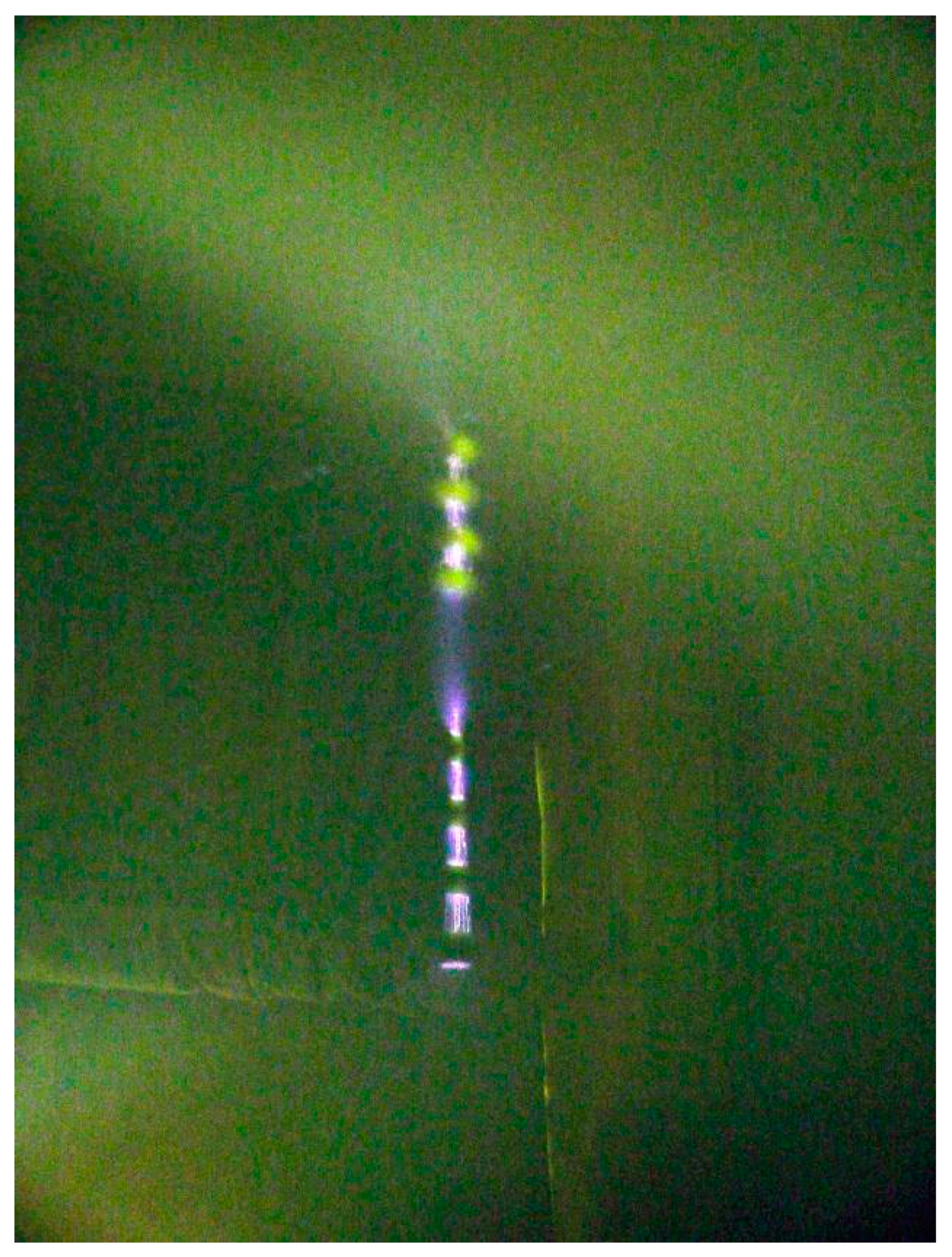
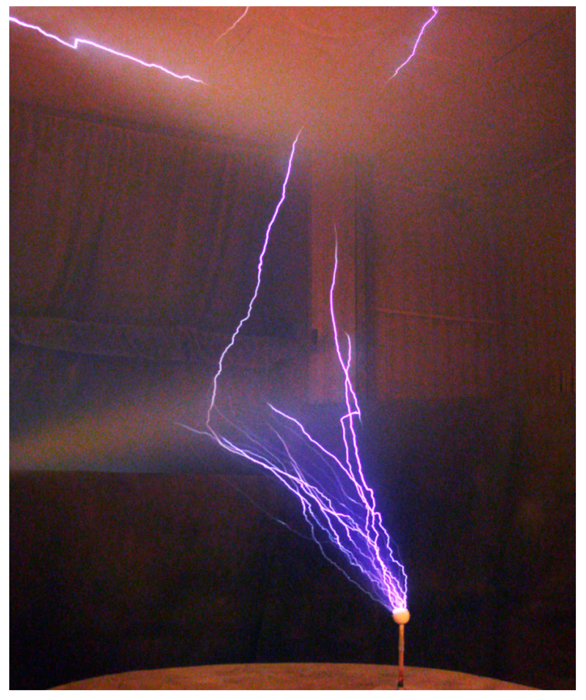
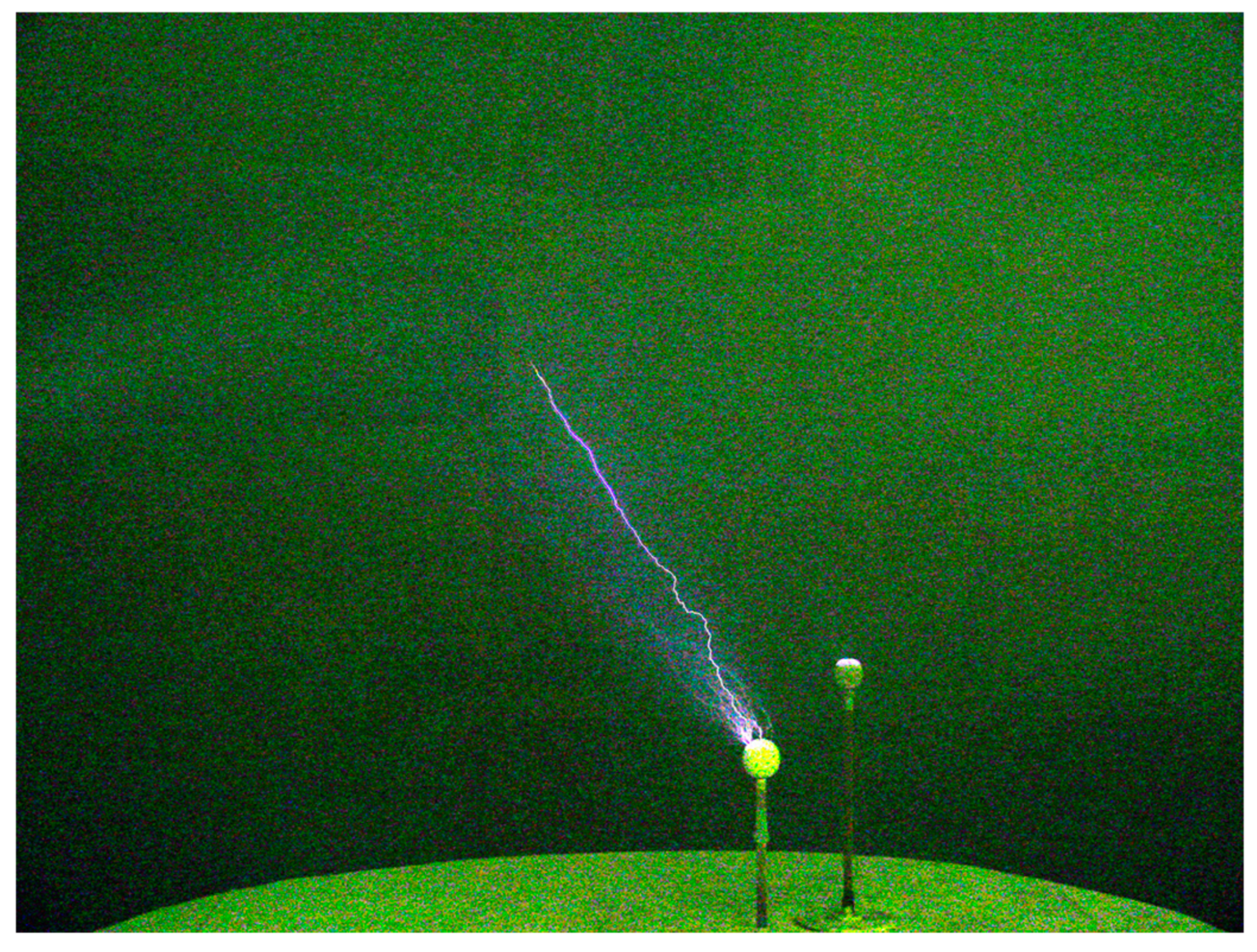
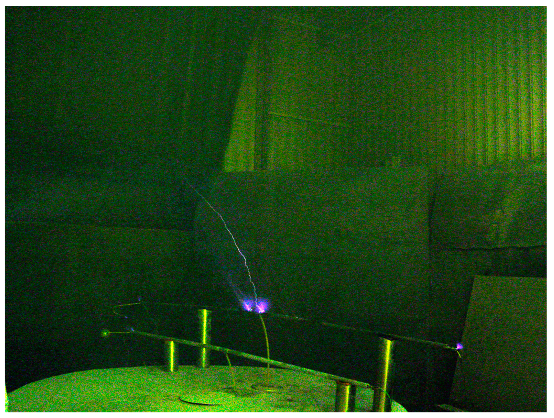
- Streamer corona and upward leader discharge form under the influence of a thundercloud’s electromagnetic field on a grounded object (e.g., transmission tower). Electromagnetic radiation from the upward discharge affects the functioning of the sensors and antennas located on or close to the tower (Figure 5a),
- -
- Streamer corona and upward leader discharge form under the influence of a thundercloud’s electromagnetic field on a middle segment of a lightning protection wire. This affects the functioning of the sensors and antennas located in the middle segment of the phase wire (Figure 5b).
3. Results
4. Discussion
- -
- Transmission systems working from sensors with frequency of 915 MHz, located on air transmission lines [1];
- -
- Systems, transmitting data on relatively small distances, e.g., using frequencies 434 MHz, 868 MHz for autonomous monitoring systems;
- -
5. Conclusions
Author Contributions
Funding
Institutional Review Board Statement
Informed Consent Statement
Data Availability Statement
Conflicts of Interest
References
- McCall, J.C.; Spillane, P.; Lindsey, K. Determining Crossing Conductor Clearance Using Line-Mounted LiDAR. In Proceedings of the CIGRE US National Committee 2015 Grid of the Future Symposium, Paris, France, 11–13 October 2015. Lindsey Publication Number 11T-001 CROSSING CONDUCTOR TLM. [Google Scholar]
- Liu, Y.; Yin, H.; Wu, T. Transmission Line on-line Monitoring System Based on Ethernet and McWiLL. In Proceedings of the International Conference on Logistics Engineering, Management and Computer Science, Shenyang, China, 29–31 July 2015; pp. 680–683. [Google Scholar]
- Working Group on Monitoring & Rating of Subcommittee 15.11 on Overhead Lines. Real-Time Overhead Transmission-Line Monitoring for Dynamic Rating. IEEE Trans. Power Deliv. 2016, 31, 921–927. [Google Scholar] [CrossRef]
- Zhirui, L.; Shengsuo, N.; Nan, J. Current Status and Development Trend of AC Transmission Line Parameter Measurement. Autom. Electr. Power Syst. 2017, 41, 181–191. [Google Scholar]
- Hu, Y.; Liu, K. Inspection and Monitoring Technologies of Transmission Lines with Remote Sensing; Academic Press: Cambridge, MA, USA, 2017. [Google Scholar]
- Li, S.; Li, J. Condition monitoring and diagnosis of power equipment: Review and prospective. High Volt. 2017, 2, 82–91. [Google Scholar] [CrossRef]
- Singh, R.; Choudhury, S.; Gehlot, A. Intelligent Communication, Control and Devices: Proceedings of the ICICCD 2017; Springer Nature Singapore Pte Ltd.: Singapore, 2018. [Google Scholar]
- Deng, C.-J. Challenges and Prospects of Power Transmission Line Intelligent Monitoring Technology. Am. Res. J. Comput. Sci. Inf. Technol. 2019, 4, 1–11. [Google Scholar]
- Wydra, M.; Kubaczynski, P.; Mazur, K.; Ksiezopolski, B. Time-Aware Monitoring of Overhead Transmission Line Sag and Temperature with LoRa Communication. Energies 2019, 12, 505. [Google Scholar] [CrossRef] [Green Version]
- Xing, Z.; Cui, W.; Liu, R.; Zheng, Z. Design and Application of Transmission Line Intelligent Monitoring System. E3S Web Conf. 2020, 185, 01063. [Google Scholar] [CrossRef]
- Chen, H.; Qian, Z.; Liu, C.; Wu, J.; Li, W.; He, X. Time-Multiplexed Self-Powered Wireless Current Sensor for Power Transmission Lines. Energies 2021, 14, 1561. [Google Scholar] [CrossRef]
- Ahmad, M.R.; Esa, M.R.M.; Cooray, V.; Dutkiewicz, E. Interference from cloud-to-ground and cloud flashes in wireless communication system. Electr. Power Syst. Res. 2014, 113, 237–246. [Google Scholar] [CrossRef]
- Hoole, P.R.P.; Sharip, M.R.M.; Fisher, J.; Pirapaharan, K.; Othman, A.K.H.; Julai, N.; Rufus, S.A.; Sahrani, S.; Hoole, S.R.H. Lightning Protection of Aircraft, Power Systems and Houses Containing IT Network Electronics. J. Telecommun. Electron. Comput. Eng. 2017, 9, 3–10. [Google Scholar]
- Borisov, R.K.; Zhulikov, S.S.; Koshelev, M.A.; Maksimov, B.K.; Mirzabekyan, G.Z.; Turchaninova, Y.S.; Khrenov, S.I. A Computer-Aided Design System for Protecting Substations and Overhead Power Lines from Lightning. Russ. Electr. Eng. 2019, 90, 86–91. [Google Scholar] [CrossRef]
- Lysov, N.; Temnikov, A.; Chernensky, L.; Orlov, A.; Belova, O.; Kivshar, T.; Kovalev, D.; Voevodin, V. Physical Simulation of the Spectrum of Possible Electromagnetic Effects of Upward Streamer Discharges on Model Elements of Transmission Line Monitoring Systems Using Artificial Thunderstorm Cell. Appl. Sci. 2021, 11, 8723. [Google Scholar] [CrossRef]
- Temnikov, A.G. Using of artificial clouds of charged water aerosol for investigations of physics of lightning and lightning protection. Processing of the 2012 International Conference on Lightning Protection (ICLP), Vienna, Austria, 2–7 September 2012. [Google Scholar] [CrossRef]
- Makalsky, L.M.; Orlov, A.V.; Temnikov, A.G. Possible mechanism of lightning strokes to extra-high-voltage power transmission lines. J. Electrost. 1996, 37, 249–260. [Google Scholar] [CrossRef]
- Vasilyak, L.M.; Vereshchagin, I.P.; Glazkov, V.V.; Kononov, I.G.; Orlov, A.V.; Polyakov, D.N.; Sinkevich, O.A.; Sokolova, M.V.; Temnikov, A.G.; Firsov, K.N. Investigation of electric discharges in the vicinity of a charged aerosol cloud and their interaction with a laser-induced spark. High Temp. 2003, 41, 166–175. [Google Scholar] [CrossRef]
- Temnikov, A.G.; Orlov, A.V.; Bolotov, V.N.; Tkach, Y.V. Studies of the parameters of a spark discharge between an artificial charged water-aerosol cloud and the ground. Tech. Phys. 2005, 50, 868–875. [Google Scholar] [CrossRef]
- Temnikov, A.G.; Orlov, A.V.; Chernensky, L.L.; Bolotov, V.N.; Pisarev, V.P. Influence of model hydrometeors on the final stage of a discharge from an artificial charged water aerosol cloud. Tech. Phys. 2009, 35, 1437–1445. [Google Scholar] [CrossRef]
- Temnikov, A.G.; Chernensky, L.L.; Orlov, A.V.; Lysov, N.Y.; Zhuravkova, D.S.; Belova, O.S.; Gerastenok, T.K. Application of Artificial Thunderstorm Cells for the Investigation of Lightning Initiation Problems between a Thundercloud and the Ground. Therm. Eng. 2017, 64, 994–1006. [Google Scholar] [CrossRef]
- Temnikov, A.G. Investigation of peculiarities of discharge formation from the system of artificial charged aerosol clouds of negative polarity. Electr. Power Syst. Res. 2014, 113, 3–9. [Google Scholar] [CrossRef]
- Temnikov, A.G.; Zhuravkova, D.S.; Orlov, A.V.; Lysov, N.Y. Outlook Research of Application of Model Hydrometeor Arrays for Artificial Initiation of Lightning and Thundercloud Charge Reduction. IOP Conf. Ser. Mater. Sci. Eng. 2019, 698, 044039. [Google Scholar] [CrossRef]
- Temnikov, A.G.; Orlov, A.V. Determination of the electric field of a submerged turbulent jet of charged aerosol. Electr. Technol. 1996, 3, 49–62. [Google Scholar]
- Vereshchagin, I.P.; Temnikov, A.G.; Orlov, A.V.; Stepanyanz, V.G. Computation of mean trajectories of charged aerosol particles in turbulent jets. J. Electrost. 1997, 40–41, 503–508. [Google Scholar] [CrossRef]
- Temnikov, A.G. Dynamics of electric field formation inside the artificially charged aerosol cloud and in a space near its boundaries. In Proceedings of the 12th International Conference on Atmospheric Electricity, Versal, France, 9–13 June 2003. ThC3-017-196. [Google Scholar]
- Temnikov, A.G.; Chernensky, L.L.; Orlov, A.V.; Kivshar, T.K.; Lysov, N.Y.; Belova, O.S.; Zhuravkova, D.S. Peculiarities of the electric field calculation of the artificial thunderstorm cells. Int. J. Circuits Syst. Signal Process. 2018, 12, 305–311. [Google Scholar]
- Rakov, V.A.; Uman, M.A. Lightning: Physics and Effects; Cambridge University Press: Boca Raton, FL, USA, 2003. [Google Scholar]
- Syssoev, V.S.; Kostinskiy, A.Y.; Makalskiy, L.M.; Rakov, A.V.; Andreev, M.G.; Bulatov, M.U.; Sukharevsky, D.I.; Naumova, M.U. A Study of Parameters of the Counterpropagating Leader and its Influence on the Lightning Protection of Objects Using Large-Scale Laboratory Modeling. Radiophys. Quantum Electron. 2014, 56, 839–845. [Google Scholar] [CrossRef]
- Kostinskiy, A.Y.; Syssoev, V.S.; Mareev, E.; Rakov, V.; Andreev, M.G.; Bogatov, N.; Makal’Sky, L.M.; Sukharevsky, D.I.; Aleshchenko, A.; Kuznetsov, V.; et al. Electric discharges produced by clouds of charged water droplets in the presence of moving conducting object. J. Atmos. Sol. Terr. Phys. 2015, 135, 36–41. [Google Scholar] [CrossRef]
- Kostinskiy, A.Y.; Syssoev, V.S.; Bogatov, N.A.; Mareev, E.A.; Andreev, M.G.; Makalsky, L.M.; Sukharevsky, D.I.; Rakov, V.A. Infrared images of bidirectional leaders produced by the cloud of charged water droplets. J. Geophys. Res. Atmos. 2015, 120, 10,728–10,735. [Google Scholar] [CrossRef] [Green Version]
- Kostinskiy, A.Y.; Syssoev, V.S.; Bogatov, N.A.; Mareev, E.A.; Andreev, M.G.; Makalsky, L.M.; Sukharevsky, D.I.; Rakov, V.A. Observation of a new class of electric discharges within artificial clouds of charged water droplets and its implication for lightning initiation within thunderclouds. Geophys. Res. Lett. 2015, 42, 8165–8171. [Google Scholar] [CrossRef] [Green Version]
- Kostinskiy, A.Y.; Syssoev, V.S.; Bogatov, N.; Mareev, E.; Andreev, M.G.; Bulatov, M.U.; Makal’Sky, L.M.; Sukharevsky, D.I.; Rakov, V.A. Observations of the connection of positive and negative leaders in meter-scale electric discharges generated by clouds of negatively charged water droplets. J. Geophys. Res. Atmos. 2016, 121, 9756–9766. [Google Scholar] [CrossRef]
- Rakov, V.A.; Mareev, E.A.; Tran, M.D.; Zhu, Y.; Bogatov, N.A.; Kostinskiy, A.Y.; Syssoev, V.S.; Lyu, W. High-Speed Optical Imaging of Lightning and Sparks: Some Recent Results. IEEJ Trans. Power Energy. 2018, 138, 321–326. [Google Scholar] [CrossRef]
- Mazur, V.A. Principles of Lightning Physics; IoP Publishing: Bristol, UK; New York, NY, USA, 2016. [Google Scholar]
- Sharma, S.R.; Cooray, V.; Fernando, M.; Miranda, F.J. Temporal features of different lightning events revealed from wavelet transform. J. Atmos. Sol. Terr. Phys. 2011, 73, 507–515. [Google Scholar] [CrossRef]
- Esa, M.R.M.; Ahmad, M.R.; Cooray, V. Wavelet analysis of the first electric field pulse of lightning flashes in Sweden. Atmos. Res. 2014, 138, 253–267. [Google Scholar] [CrossRef]
- Temnikov, A.G.; Chernensky, L.L.; Belova, O.S.; Orlov, A.V.; Zimin, A.S. Spectral characteristics of discharges from artificial charged aerosol cloud. In Proceedings of the IEEE Conference Publications: Lightning Protection (ICLP), Proceedings of the 2012 International Conference on Lightning Protection, Shanghai, China, 11–18 October 2014. Article number 6973333. [Google Scholar]
- Cooray, V. Lightning Electromagnetics; IET Publishing: London, UK, 2012. [Google Scholar]
- Cooray, V.; Cooray, G. Electromagnetic fields of accelerating charges: Applications in lightning protection. Electr. Power Syst. Res. 2017, 145, 234–247. [Google Scholar] [CrossRef]
- Cooray, V.; Cooray, G. The Electromagnetic Fields of an Accelerating Charge: Applications in Lightning Return-Stroke Models. IEEE Trans. Electromagn. Compat. 2010, 52, 944–955. [Google Scholar] [CrossRef]
- Cooray, V.; Cooray, G. Electromagnetic radiation field of an electron avalanche. Atmos. Res. 2012, 117, 18–27. [Google Scholar] [CrossRef]
- Shi, F.; Liu, N.; Dwyer, J.R.; Ihaddadene, K.M.A. VHF and UHF Electromagnetic Radiation Produced by Streamers in Lightning. Geophys. Res. Lett. 2019, 46, 443–451. [Google Scholar] [CrossRef] [Green Version]
- Gushchin, M.E.; Korobkov, S.V.; Zudin, I.Y.; Nikolenko, A.S.; Mikryukov, P.A.; Syssoev, V.S.; Sukharevsky, D.I.; Orlov, A.I.; Naumova, M.Y.; Kuznetsov, Y.A.; et al. Nanosecond electromagnetic pulses generated by electric discharges: Observation with clouds of charged water droplets and implications for lightning. Geophys. Res. Lett. 2021, 48, e2020GL092108. [Google Scholar] [CrossRef]
- Rochelle, P. ORBCOMM Announces Commercial Service for Its Final 11 OG2 Satellites. 1 March 2016. Available online: https://www.orbcomm.com/en/company-investors/news/2016/orbcomm-announcescommercial-service-for-its-final-11-og2-satellites (accessed on 30 August 2021).
- Our Mission Is Space Communication. Available online: http://www.gonets.ru/eng/company/mission/ (accessed on 30 August 2021).


| Source of Effect | Upward Discharge (Rod) | Upward Discharge (Elongated) | ||
|---|---|---|---|---|
| Amplification Coefficient | ΔT, µs | |Imax|, A | ΔT, µs | |Imax|, A |
| Group I | 1.2 | 0.9 | 1.1 | 1.2 |
| Group II | 0.3 | 1.6 | 0.5 | 1.3 |
| Group III | 0.7 | 1.0 | 1.0 | 1.2 |
| Antenna | A1 | A2 | ||
|---|---|---|---|---|
| Parameters | ΔT, ms | |Imax|, A | ΔT, µs | |Imax|, A |
| Average | 1.1 | 1.1 | 1.8 | 1.8 |
| Maximum | 4.5 | 3.1 | 9.8 | 3.3 |
| Source of Effect | Rod Elements | Elongated Elements | Antennas | |||||
|---|---|---|---|---|---|---|---|---|
| AQ | Group I | Group II | Group III | Group I | Group II | Group III | A1 | A2 |
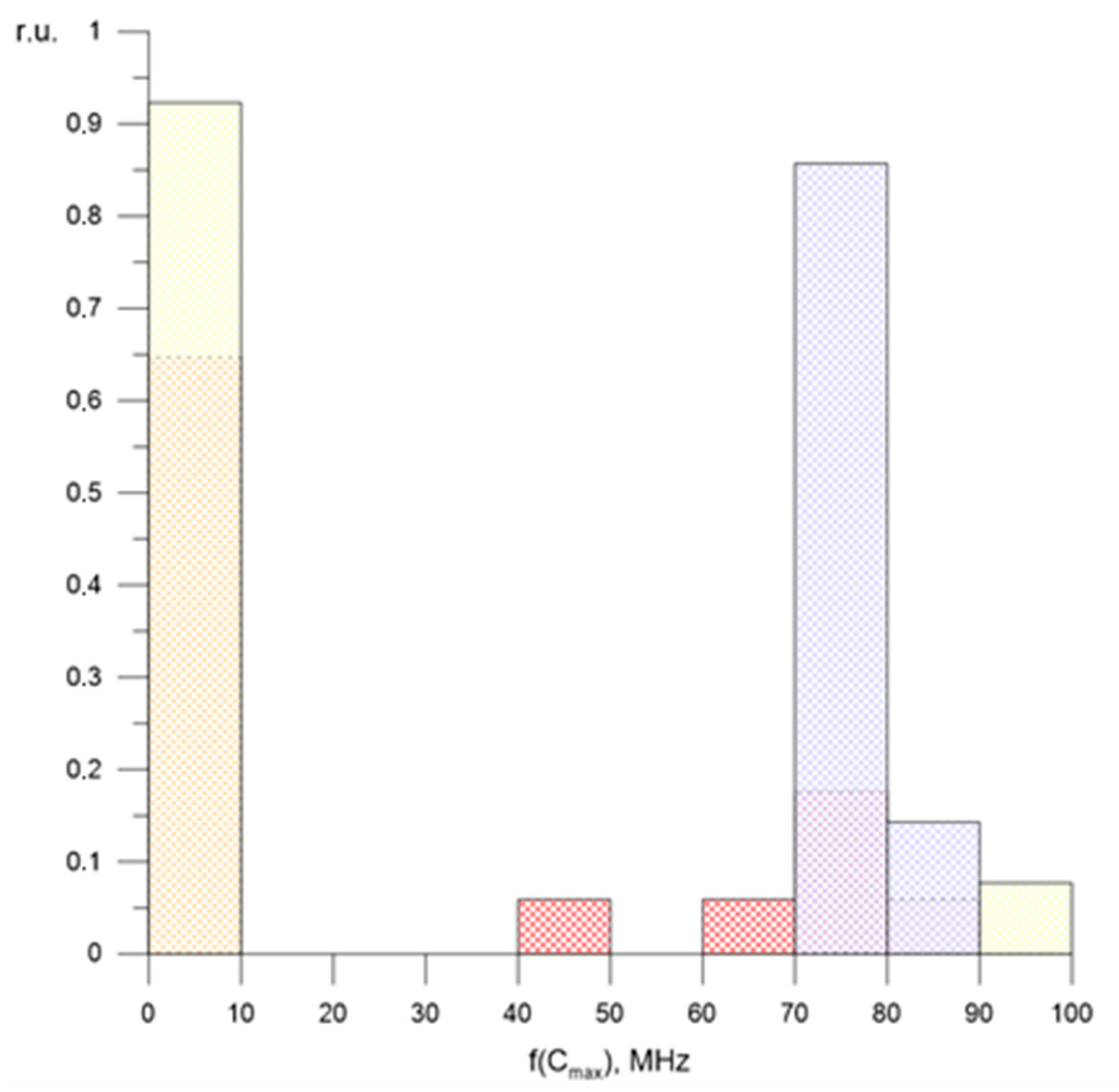
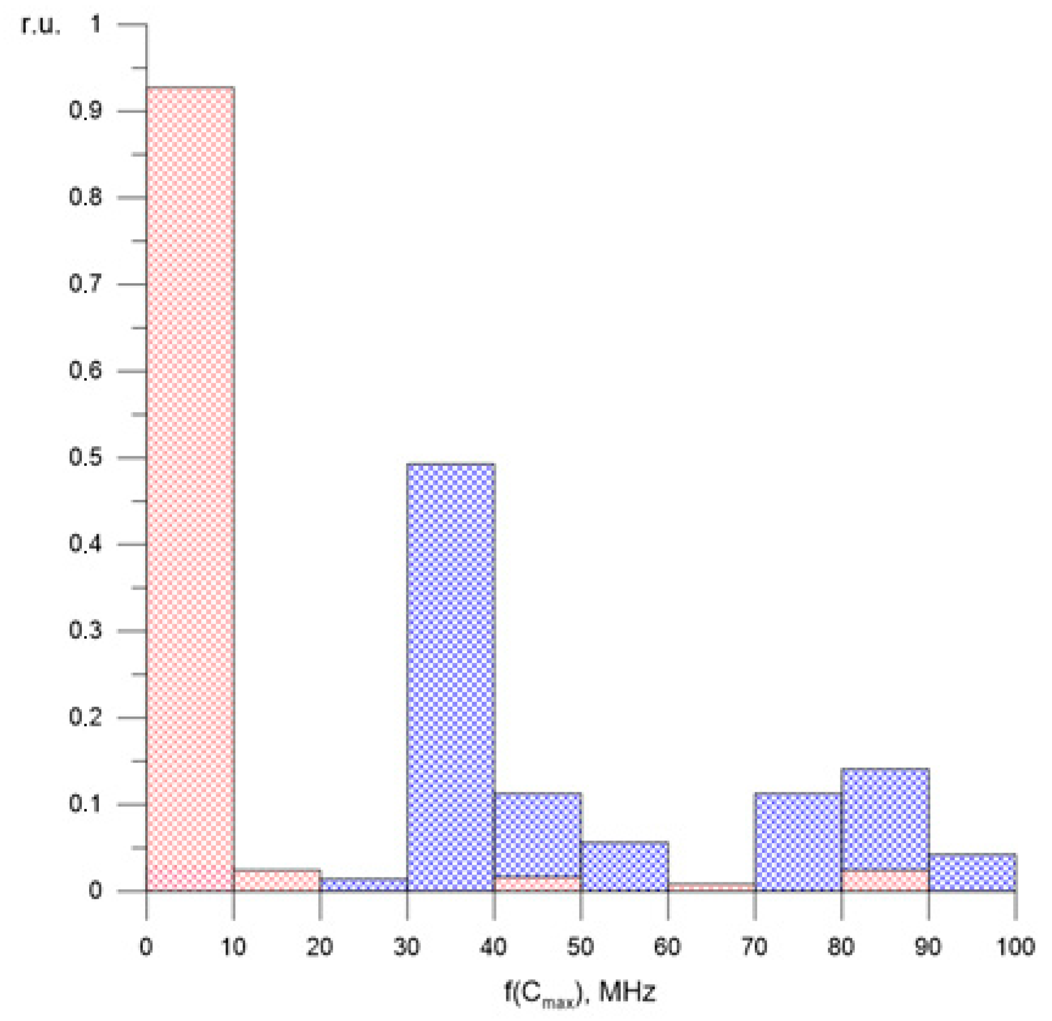
| fmax, MHz | 122 | 756 | 391 | 119 | 785 | 467 | 602.3 | 144.4 |
| f(Cmax), MHz | 11.1 | 77 | 14.7 | 9.6 | 73 | 12.3 | 51.6 | 10.5 |
Publisher’s Note: MDPI stays neutral with regard to jurisdictional claims in published maps and institutional affiliations. |
© 2021 by the authors. Licensee MDPI, Basel, Switzerland. This article is an open access article distributed under the terms and conditions of the Creative Commons Attribution (CC BY) license (https://creativecommons.org/licenses/by/4.0/).
Share and Cite
Lysov, N.; Temnikov, A.; Chernensky, L.; Orlov, A.; Belova, O.; Kivshar, T.; Kovalev, D.; Voevodin, V. Artificial Negative Polarity Thunderstorm Cell Modeling of Nearby Incomplete Upward Discharges’ Influence on Elements of Monitoring Systems for Air Transmission Lines. Energies 2021, 14, 7100. https://doi.org/10.3390/en14217100
Lysov N, Temnikov A, Chernensky L, Orlov A, Belova O, Kivshar T, Kovalev D, Voevodin V. Artificial Negative Polarity Thunderstorm Cell Modeling of Nearby Incomplete Upward Discharges’ Influence on Elements of Monitoring Systems for Air Transmission Lines. Energies. 2021; 14(21):7100. https://doi.org/10.3390/en14217100
Chicago/Turabian StyleLysov, Nikolay, Alexander Temnikov, Leonid Chernensky, Alexander Orlov, Olga Belova, Tatiana Kivshar, Dmitry Kovalev, and Vadim Voevodin. 2021. "Artificial Negative Polarity Thunderstorm Cell Modeling of Nearby Incomplete Upward Discharges’ Influence on Elements of Monitoring Systems for Air Transmission Lines" Energies 14, no. 21: 7100. https://doi.org/10.3390/en14217100
APA StyleLysov, N., Temnikov, A., Chernensky, L., Orlov, A., Belova, O., Kivshar, T., Kovalev, D., & Voevodin, V. (2021). Artificial Negative Polarity Thunderstorm Cell Modeling of Nearby Incomplete Upward Discharges’ Influence on Elements of Monitoring Systems for Air Transmission Lines. Energies, 14(21), 7100. https://doi.org/10.3390/en14217100