Article

3D Unsteady Simulation of a Scale-Up Methanation Reactor with Interconnected Cooling Unit

1
Institut de Mécanique des Fluides de Toulouse, 31400 Toulouse, France
2
State Key Laboratory of Clean Energy Utilization, Zhejiang University, Hangzhou 310058, China
*
Author to whom correspondence should be addressed.
Energies 2021, 14(21), 7095; https://doi.org/10.3390/en14217095
Submission received: 17 September 2021 / Revised: 17 October 2021 / Accepted: 20 October 2021 / Published: 30 October 2021
(This article belongs to the Special Issue Advances in Thermophysics of Multiphase Flow)

Abstract

:
The production of synthetic natural gas (SNG) via methanation has been demonstrated by experiments in bench scale bubbling fluidized bed reactors. In the current work, we focus on the scale-up of the methanation reactor, and a circulating fluidized bed (CFB) is designed with variable diameter according to the characteristic of methanation. The critical issue is the removal of reaction heat during the strongly exothermic process of the methanation. As a result, an interconnected bubbling fluidized bed (BFB) is utilized and connected with the reactor in order to cool the particles and to maintain system temperature. A 3D model is built, and the influences of operating temperature on H2, CO conversion and CH4 yield are evaluated by numerical simulations. The instantaneous and time-averaged flow behaviors are obtained and analyzed. It turns out that the products with high concentrations of CH4 are received at the CFB reactor outlet. The temperature of the system is kept under control by using a cooling unit, and the steady state of thermal behavior is achieved under the cooling effect of BFB reactor. The circulating rate of particles and the cooling power of the BFB reactor significantly affect the performance of reactor. This investigation provides insight into the design and operation of a scale-up methanation reactor, and the feasibility of the CFB reactor for the methanation process is confirmed.

1. Introduction

The production of synthetic natural gas from fossil or renewable sources via methanation technology is beneficial for energy supplements and a reduction in emissions [1]. The reactions occur on the surface of catalysts for which the practical component is the metal oxides of Ni, Co, Ru and Fe [2]. The main reactions in the methanation reactor are CO methanation and water-gas shift reaction (WGS).
CO + 3 H 2 CH 4 + H 2 O Δ H 298 K = 206.28 kJ / mol
CO + H 2 O CO 2 + H 2 Δ H 298 K = 41.16 kJ / mol
The reactions are strongly exothermic, and the favorable temperature is lower than 400 degrees considering both thermodynamics and kinetics. Heat removal is essential for the methanation reactor, and the hotspot temperature will result in carbon deposition, the migration and agglomeration of catalysts [3]. Researchers are continuing on the study of producing methane via methanation [4,5]. In the past 50 years, methanation has been verified and investigated in different types of reactors, such as fixed-bed, fluidized reactors and tube-wall reactors [6,7]. For the fixed bed reactor, one can find the hotspot temperature. Compared with the fixed bed reactor, the fluidized bed reactor is simple in construction, and it is easy in terms of operation. Moreover, the fluidized bed reactor is nearly isothermal due to good heat and mass transfers. A summary of the fluidized bed methanation reactors can be found in the work of Kopyscinski [8]. The experiments have been successfully carried out, and technical feasibility has been validated [9,10]. The most important principle is the effective removal of heat released by the reaction and temperature control in order to maintain catalyst life. However, the complexity of flow behavior and the strongly exothermic effect render it hard to design and scale-up the reactors [11,12]. During the experiments, a bench-scale oil-cooled reactor was used to control the temperature, and the reaction heat was negligible for very low reaction intensities [13,14,15]. In the numerical work of Liu et al. [16], the methanation process was simulated numerically by using the open source package OpenFOAM. The isothermal flow assumption was adopted, and the energy equation was not included in their work. Although the products were predicted, the isothermal assumption was not suitable for the exothermic process. Li et al. [15] simulated the bubbling fluidized with a mandatory assumption that the system was cooled by media with temperatures at 390 °C in order to guarantee that the outlet temperature was 400 °C. In the work of Chein [17], the constant cooling temperature was utilized for calculating heat transfer.
The literature review shows that there are no publications about the scale-up of a methanation reactor. Moreover, temperature control in the methanation reactor during the highly exothermic process has not been investigated. By focusing on these topics, the primary motivation of this work is to build the scale-up methanation reactor and to study reaction characteristics. The removal of reaction heat will be analysed for steady operation. A circulating fluidized bed reactor with variable diameter is designed for guaranteeing the production of methane. Temperature control in the reactor is the critical content for the methanation process. A bubbling fluidized bed reactor is used for cooling the particles and to remove reaction heat. The entire work is organized as follow. The mathematical model adopted in this work is shown in Section 2. In Section 3, the model is validated, and the simulated results are compared with the experimental measurements. In Section 4.1, the original intention of the design of the scale-up reactor is explained. Then, the performance of the reactor with the cooling unit is analyzed. Finally, we conclude Section 5 for the scale-up reactor.

2. Mathematical Models

A Eulerian–Eulerian two-fluid model has been adopted to describe the evolution of phases and the continuity equations, which are described as follows:
( α g ρ g ) t + · ( α g ρ g u g ) = 0
( α s ρ s ) t + · ( α s ρ s u s ) = 0
where α , u and ρ denote volume fraction, velocity and density, respectively. The source terms for the mass transfer are zero because only the homogeneous reactions are considered in the current investigation and no mass transfer between phases.
The momentum conservation equations for gas phase and solid phase are as follows,
α g ρ g u g t + · ( α g ρ g u g u g ) = α g p + · ( α g τ g ) + α g ρ g g + β ( u s u g )
α s ρ s u s t + · ( α s ρ s u s u s ) = α s p + · ( α s τ s ) + α s ρ s g + β ( u g u s )
τ g and τ s are the stress tensors for the gas phase and solid phase, shown in Table 1. β is the momentum interphase transfer coefficient and can be simulated as the combination between the Wen and Yu model and Ergun model [18].
β = 3 4 C D α g α s ρ g | u g u s | d s α s 2.65 α s < 0.2 150 μ g α s 2 α s d s 2 + 1.75 α s ρ g d s | u g u s | α s 0.2
C D = 24 R e α g 1 + 0.15 ( R e α g ) 0.687 R e < 1000 0.44 R e 1000
R e = ρ g d s | u g u s | μ g
The standard k ε model is adopted in current work:
t α g ρ g k + · α g ρ g u g k = · α g μ t σ k k + α g G k α g ρ g ε
t α g ρ g ε + · α g ρ g u g ε = · α g μ t σ ε ε + α g ε k ( C 1 G K C 2 ρ g ε ) α g ρ g ε
where k and ε are the turbulent kinetic energy and dissipation rate of turbulent energy, respectively. The constants involved in the k ε model are C 1 = 1.44 and C 2 = 1.92 and the turbulent Prandtl number includes σ k = 1.0 , σ ε = 1.3 and C μ = 0.09 .
The kinetic theory of granular flow (KTGF) is adopted in this work and the transport equation of granular temperature is written as follows: [19]
3 2 t ( α s ρ s θ ) + · ( α s ρ s θ ) u s = ( p s I + τ s ) : u s + · ( k s θ ) γ s 3 β θ + D g s
where p s is the solid pressure, and k s is the conductivity of fluctuating energy. γ s is the dissipation of fluctuation kinetic energy. D g s is the energy dissipation rate per unit volume.
The energy conservation equations for gas and solid phases are written as follows:
t α g ρ g H g + · α g ρ g u g H g = κ g T g + h T g T s + S g
t α s ρ s H s + · α s ρ s u s H s = κ s T s + h T s T g + S s
where H, T and S are the specific enthalpy, temperature and source terms due to reaction, respectively. κ represents thermal conductivity. h is the interfacial heat transfer coefficient.
The species transport equation is solved, and it can be written as follows:
α g ρ g Y g , i t + · ( α g ρ g u g Y g , i ) = · ( α g J g , i ) + ψ g , i
where Y g , i represents the mass fraction gas species i. J g , i is diffusion flux of species i. ψ g , i represents the production rate. ψ g , C O = Φ r 1 , C O + Φ r 2 , C O , ψ g , C H 4 = W C H 4 W C O Φ r 1 , C O , ψ g , H 2 = 3 W H 2 W C O Φ r 1 , C O W H 2 W C O Φ r 2 , C O , ψ g , H 2 O = W H 2 O W C O Φ r 1 , C O + W H 2 O W C O Φ r 2 , C O and ψ g , C O 2 = W C O 2 W C O Φ r 2 , C O . Moreover, Φ r 1 and Φ r 2 are the reaction rates of methanation and WGS reaction shown in Section 1, which are written as follows [9,17]:
R M E T H = k 1 P H 2 2.5 P C H 4 P H 2 O P H 2 3 P C O K e q 1 / D E N 2
R W G S = k 2 P H 2 P C O P H 2 O P C O 2 P H 2 K e q 2 / D E N 2
D E N = 1 + K C H 4 P C H 4 + K C O P C O + K H 2 P H 2 + K H 2 O P H 2 O P H 2
where R M E T H and R W G S are in the units mol · s 1 · kg c a t 1 . The partial pressure of gas species is measured by the unit Pa. R is the ideal gas constant, R = 8.314 J · mol 1 · K 1 . The constants used in Equations (14)–(16) are calculated based on an Arrhenius-type dependency, and the parameters are listed in Table 2.
The reaction degree of CO methanation and WGS reaction can be evaluated by the conversion rate of reactants and the selectivity of products. Moreover, they can be used for characterizing the performance of a reactor. The definitions of the conversion rates of CO and H2 are as follows:
X C O = n C O , i n n C O , o u t n C O , i n × 100
X H 2 = n H 2 , i n n H 2 , o u t n H 2 , i n × 100
The selectivities of the CH4 and CO2 are defined as:
S C H 4 = n C H 4 , o u t n C O , i n n C O , o u t × 100
S C O 2 = n C O 2 , o u t n C O , i n n C O , o u t × 100
where n is the molar flow rate of gaseous components.

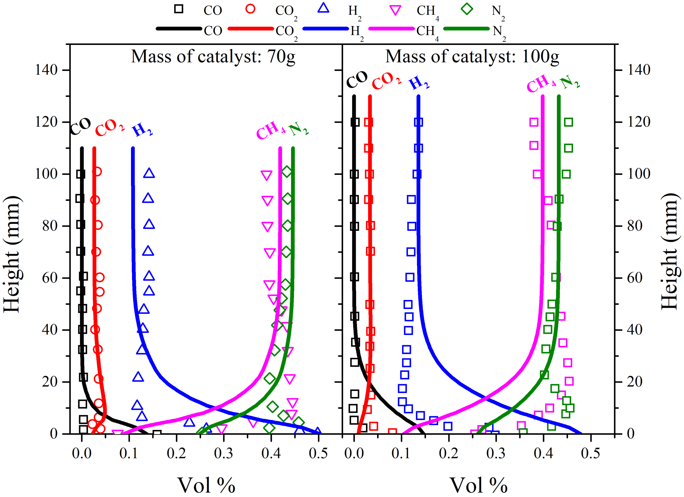
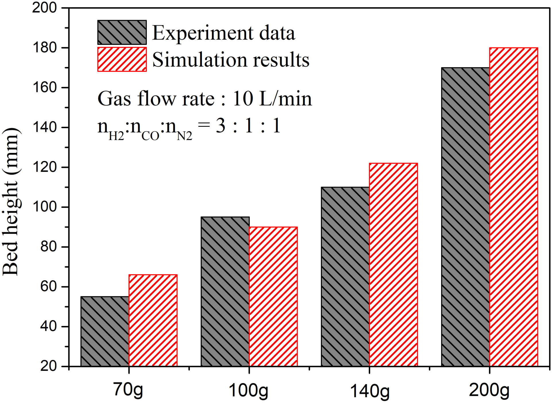
3. Validation of the Model

The validation of the model is carried out in this section. Kopyscinski et al. [9] investigated experimentally the behavior of the methanation process in bench-scale fluidized bed reactors. Currently, it is the one of the rare published experimental works to the best of the authors’ knowledge. The height and diameter of reactor used in the work of Kopyscinski are 0.2 m and 0.052 m, respectively. The catalyst used in experiments is a commercial Ni/Al2O3 particle. The diameter and density of particles are 0.1 mm and 2000 kg/m3, respectively. The 3D simulations are built and set according to the experiments. The mass inventory ranges from 70 g to 200 g. The inlet rate of fluidizing gas is 10 LN/min, and the mole ratio between CO and H2 is 1:3. The N2 is used as the balance gas. A no-slip wall boundary condition is adopted for solid phase at the wall. Each case is carried out for 30 s, and the data during the last 10 s are used for time-averaged results.
The simulated gas species concentrations with different masses of catalysts are shown in Figure 1. For the case with 70 g catalyst, the concentration of H2 decreases rapidly from the initial value at inlet (60 vol%) to 10.9 vol%. The concentration of CH4 increases to approximately 41.8 vol% simultaneously. CO diminishes at the beginning of the bed. The concentration of N2 increases due to the volume contraction during the methanation process. CO2 is also detected in the reactor, and the constant value for the concentration at the top part is approximately 2.6 vol%. The experimental values from Reference [9] are also plotted in the figure as scatters. There is a slight difference between the simulation data and the experimental data. For example, the concentration of CH4 from the experiment first increases and then decreases slightly, and then it finally remains constant at the end of the bed materials. Furthermore, when it exceeds the bed, it decreases again. For this phenomenon, the explanation given by Kopyscinski et al. [9] is the mass transfer between the dense phase and bubbles, and they believe that the measured data by the probe are the concentrations of the dense phase. Near the gas inlet, CH4 is produced in the dense phase, resulting in a higher concentration of CH4 than the bubble phase. However, in the upper part, the mass transfer rate is higher than the production rate; thus, the concentration decreases. For the simulation, we obtain the gas species concentration while missing this micro phenomenon. Nevertheless, the final results are very close to the experimental data. For the case with 100 g catalysts, similar characteristics are obtained. The difference is that the bed becomes deeper with more particles and more time for the interaction between phases. The height that the curve needs to reach a constant value is higher. A possible reason for this is that heat is more brutal when transferred to the free bed. Globally, the simulated results are in good agreement with experiment’s measurements. The instantaneous snapshots of dry gas species concentration are presented in the Figure 2, corresponding to the case with 100 g catalysts at time 30 s. We can obtain an intuitive view of the distribution of the gaseous species. The reactants, CO and H2, decrease sharply near the inlet. The products are generated in the first few millimeters and then remain constant relative to the end of the bed.
The expanded bed heights with the different weights of the catalysts are estimated and shown in Figure 3. Kopyscinski et al. [9] measured the height of particles during the experiments as shown in the black column. For the simulation, we obtained the results quickly based on the time-averaged results of the solid volume fraction. The bed height increases with the raising total mass in the reactor. Furthermore, the simulation results agree well with the experiment’s data. Globally, both the flow behavior and reaction characteristics have been validated in this section and are in reasonable agreement with measurements. The validated model will be further used for investigating the performance of reactors.

4. Simulation of 3D Circulating Fluidized Bed Reactor

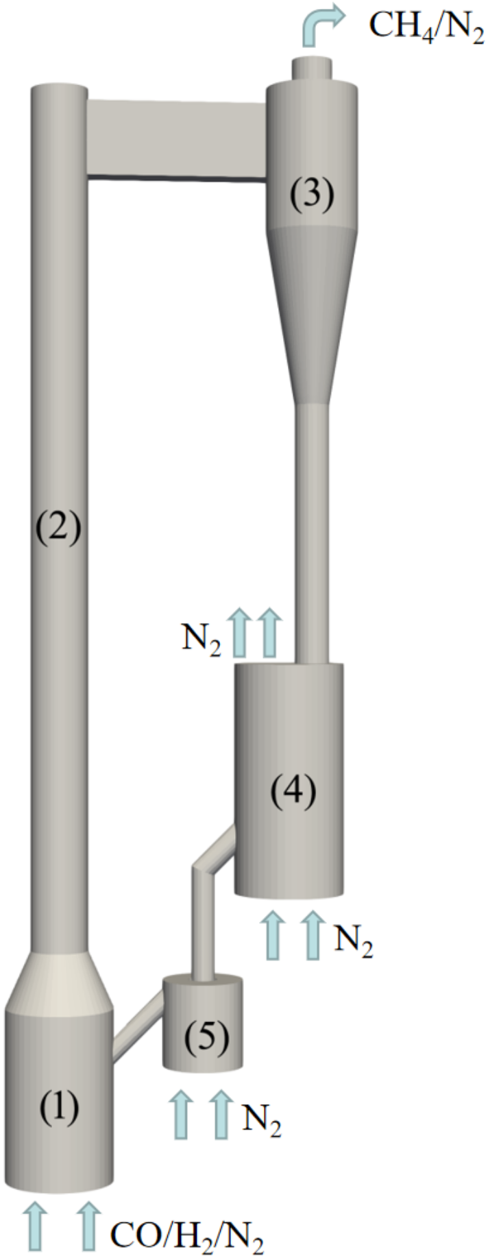
4.1. Design and Setup of Simulations

Up until this point, most works on methanation focus on the bench-scale bubbling fluidized bed or fixed bed reactors [16,17,20]. Only a few publications are published concerning the scale-up reactor, which is close to pilot/industry scale, to the authors’ best knowledge. In this section, a circulating fluidized bed reactor with an interconnected bubbling fluidized bed reactor is designed for the CO methanation process, and the configuration is shown in Figure 4. It comprises a circulating fluidized bed as the main reactor, a cyclone, a bubbling fluidized bed and a loop seal. The total height of the reactor is 1.9 m. According to the experimental measurement and our previous simulated results [9,21], the methanation reaction is a fast process, and it finishes in the region near the inlet. Considering this feature, the main reactor is redesigned with a lager diameter (0.19 m) at the bottom and a small diameter (0.1 m) at the top region. The variation of the diameter can be used to guarantee the bottom region with high solid volume fraction where methanation mainly occurs. When particles enter the riser part, they are accelerated to leave the reactor. The advantage of this improvement is to ensure that there are enough particles that can catalyze the reaction near the inlet, and it also shortens particle residence time in riser in order to avoid suffering from high temperature. A simplified cyclone connected with the riser is used to separate particles. A bubbling fluidized bed (BFB) is joined with cyclone in order to cool particles and to control the system’s temperature with a strongly exothermic process in the reactor, which is another motivation for our new design. The ‘hot’ particles are sent to the bubbling fluidized bed reactor, which is fluidized by the nitrogen gas because N2 will not participate in any reaction and does not affect the reations. The fluidization agent exchanges heat with particles, and it realizes the cooling of particles. The gas temperature and inlet rate for BFB are the decisive factors in controlling the catalyst’s temperature. A loop seal is used to send particles back into the reactor and to prevent gas leakage between reactors. It also works by controlling the flow rate of catalyst, which will influence the residence time of particles in BFB. Under the combined effect of BFB and loop seal, we realize the removal of heat and the control of system temperature.
The model validated in Section 3 is adopted to study the behavior of the scale-up reactor. The simulations are carried out by the code developed in the frame of two-fluid model, and the cell-center finite volume with the first order scheme is used. Runge–Kutta methods were adopted for handling the instability of numerical simulation. Adiabatic conditions are set for the wall. The inlet’s mole ratio between C O and H 2 is 1:3, and nitrogen is used as balance gas. For the simulations, k ε model is utilized for modeling gas turbulence. Non-slip and free slip boundary conditions are set for the solid phase at the wall and discussed in the next section. An outflow condition is set for the outlet of the reactor. The reactor works with atmosphere pressure. The catalyst is a Ni/Al2O3 particle, which is the same as that used in the experiment of Kopyscinski [9], and the solid inventory is 17.9 kg.

4.2. Results and Discussion

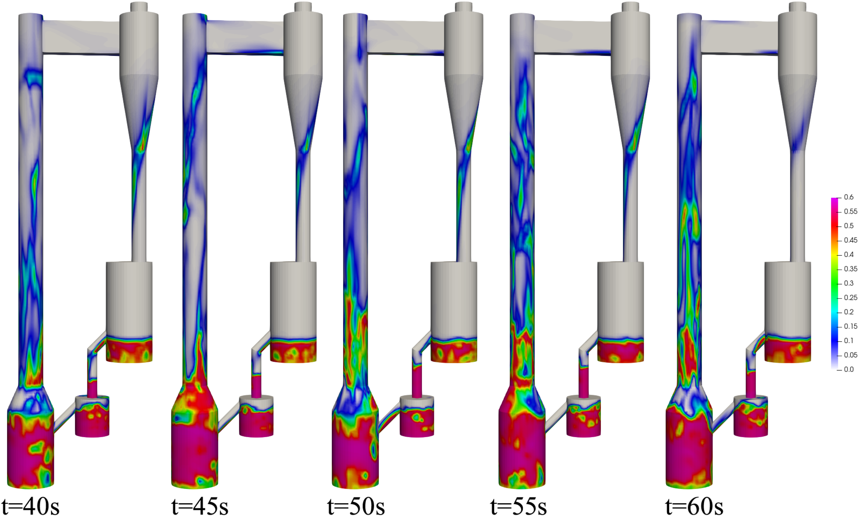
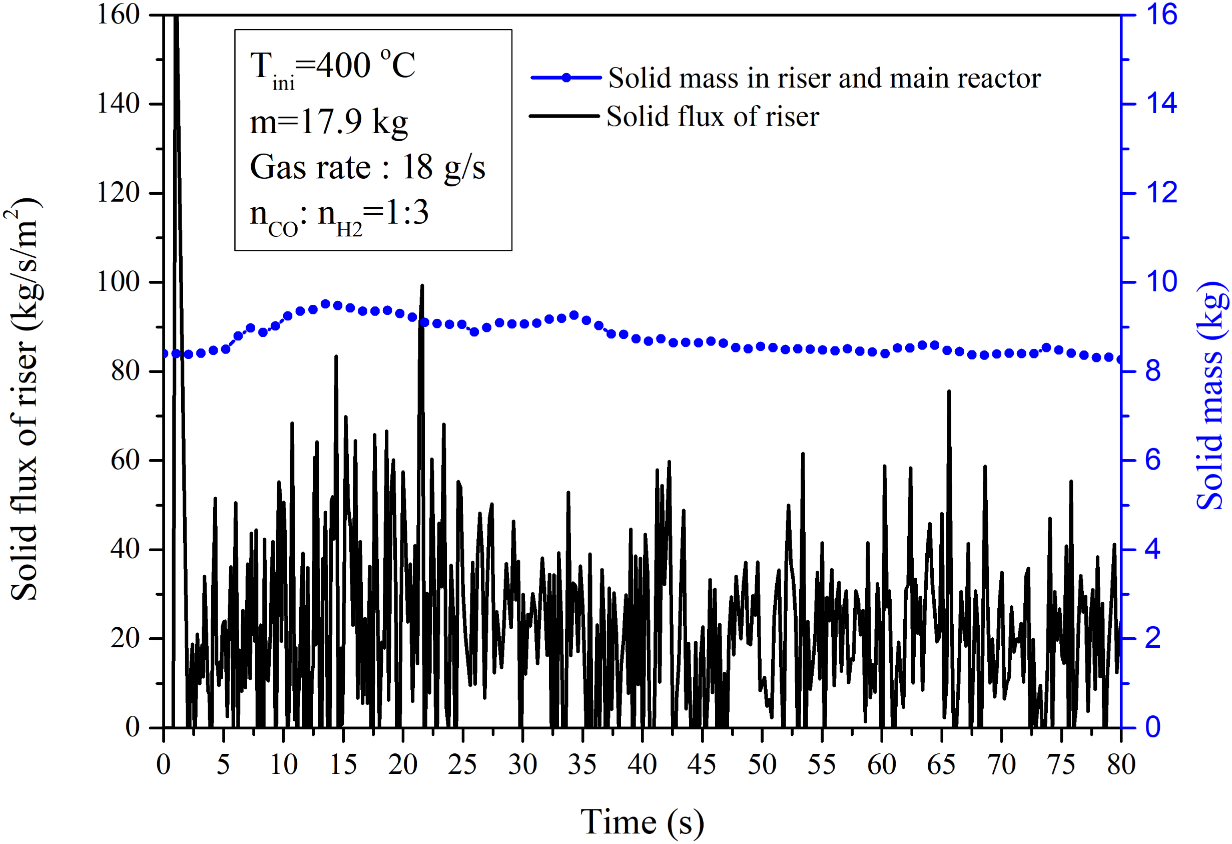
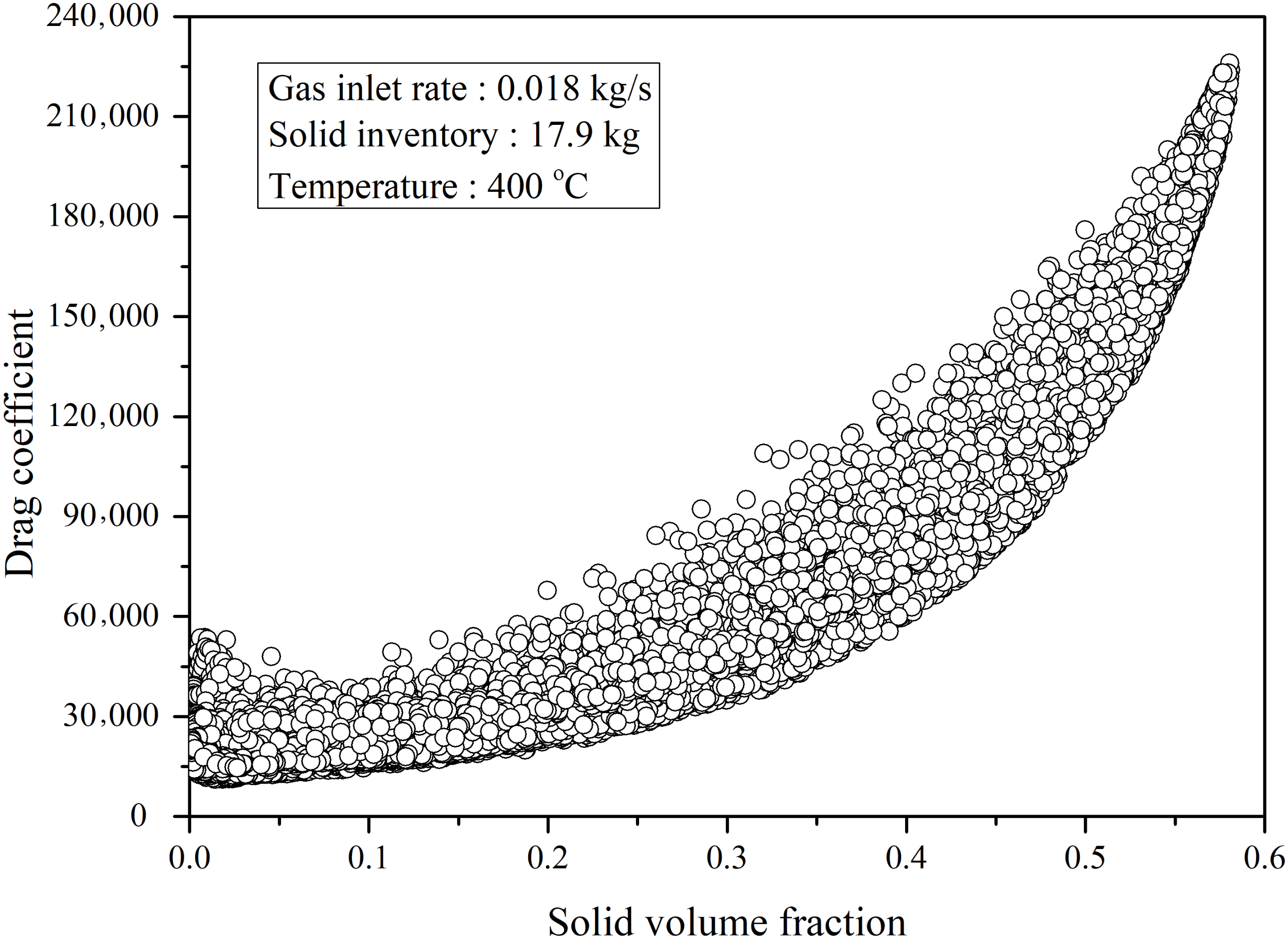
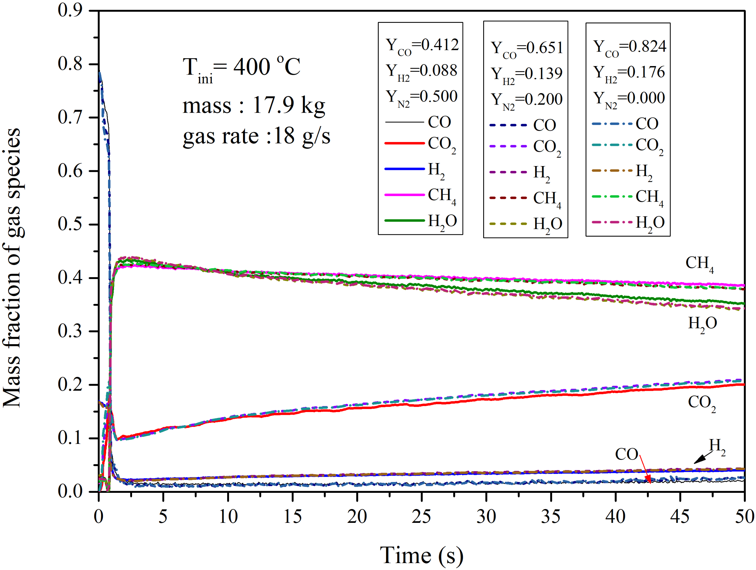
4.2.1. Performance of the Circulating Fluidized Bed Reactor

The instantaneous distribution of solid volume fraction is shown in Figure 5. The gas inlet rate is 0.018 kg/s, which is hundreds of times the inlet rate in the bench scale reactor. At initial times, the particles are located in the reactor with a volume fraction of 0.5. When the fludization gas enters the reactor, particles are fluidized, and they flow upward together with the gas phase. Due to the change of the cross section area of the reactor, two different flow patterns are formed: at the bottom, it is dense region, and it is a diluted region in the riser area. This design produces a result where, near the inlet region, the reactant concentration is high, and the solid volume fraction is also high in order to ensure the completion of methanation. In the riser, the reactant concentration is low and fewer particles are needed, and they leave the system quickly for avoid suffering from high temperatures. The particles will be separated by a cyclone, and the entrainment of particles is achieved. Then, the materials enter the bubbling fluidized bed, which is used for maintaining the system’s temperature. The particles will be sent back to the riser through the pot-seal, and circulation is realised. The asymmetric distribution of solids can be found at the bottom part due to the effect of the inlet connecting with the loop seal.
The time-averaged relative pressure for reference case is shown in Figure 6. The pressure value corresponds to the solid mass above the measurement point. Relative pressure decreases with the height of the reactor. The gradient of pressure at the bottom part is larger than that in the riser. The result reveals that most particles concentrate at the bottom of reactor, and it operates more similarly to a bubbling fluidized bed. In the riser, the relative pressure change is smaller than that at the bottom part, and the distribution of particles is nearly uniform. Several fluidization regimes exist in the reactor for the current reactor, such as the bubbling fluidized regime in the bubbling fluidized bed (the cooling unit) and the bottom part of the main reactor and the fast fluidization regime in the riser. The difference in terms of solid volume fraction is evident, as shown in Figure 5. The effect of the boundary condition on the hydrodynamic is analyzed in this section. The results predicted by free slip BC are lower than that predicted by non-slip BC. Globally, the difference is small.
The time-evolution of the mass fraction of gas species at the reactor outlet is shown in Figure 7. The initial solid inventory is 17.9 kg with a temperature of 400 °C. The gas inlet rate of the main reactor is 0.018 kg/s with 50% N2 as the balance gas. The mole ratio between CO and H2 is 1:3. This case is set as reference, and the other results will be compared with this one fin order to understand operating behavior in the following sections. From the figure, it is clear that both mass fractions of CO and H2 are very low at the outlet of the reactor. The main components at the outlet are CH4 and H2O. CO2 is also detected, which is a product of the water-gas shift reaction. The mass fraction of CH4 decreases with time, and it has not reached a steady value at the end of this case (80 s). As we are aware, both the CO methanation and water-gas shift reaction are reversible reactions. The change of temperature in the reactor influences the reaction’s direction or the competition relations. The corresponding temperature of the reference case is shown in Figure 8. The temperature increases with time due to the exothermic reaction. High temperatures will accelerate both CO methanation and water-gas shift reaction according to reaction kinetics; this is the reason for the increase in CO2 fraction, as shown in Figure 7. The mass fraction of CH4 decreases due to the enhancement of the backward reaction. Two aspects cause the decrease in H2O mass fraction: The first reason is the decrease in production from CO methanation, and the second reason is the consumption of H2O by water-gas shift reactions, which increases with temperature. From Figure 8, we can ascertain that the temperature should be well controlled, and this is the motivation for designing a bubbling fluidized bed as interconnected with a cooling reactor, and the performance will be discussed in the following section. The corresponding conversion rate of CO and H2 are 0.976 and 0.776, respectively. The selectivity of CH4 and CO2 are 0.843 and 0.156, respectively. The conversion of CO is relatively high, while the conversion of H2 is low due to the water-gas shift reaction.
Figure 9 shows the contours of mass fraction of gas species. The mass fraction of CO decreases from 0.412 at the inlet to 0.04 immediately closer to the inlet, which illustrates that CO methanation is completed very quickly at this region. The mass fraction of CH4 increases simultaneously with the maximum value. By comparing the distribution of CO2 and H2O, we can find the position where the water-gas shift reaction mainly occurs. Because we adopted a simplified cyclone, some gas products mix with the solid flow when moving into the bubbling fluidized bed reactor through the downcomer. When we compute the conversion rate or selectivity, these gas are also taken into consideration.
The time evolution of solid flux is shown in Figure 10. From 25 s, the system reaches a steady state in terms of hydrodynamics, and the time averaged solid flux at the outlet of riser (with diameter 0.1 m) is 21.65 kg/s/m2. The solid mass in the riser and main reactor is also calculated and shown in the figure, and the average value is about 8.5 kg. The residence time of solids can be calculated and it is about 50 s. In addition, we can estimate the relation between CO and catalyst particles, which can be used to design the reactor. For the reference case, 1 mole CO is under the catalysis effect of a 6.81 kg catalyst.
The profile of gas and solid vertical velocity is shown at left side of Figure 11. Velocity is positive in the center and negative near the wall. The particles flow upward in the center, and some particles flow back under the effect of wall. Two measurement heights are chosen: one is at the bottom part, and the another is in the riser. Both gas and solid increase largely when entering the riser due to the change of the cross section area. The solid volume fraction is shown at the right side of Figure 11. The solid volume fraction is high near the wall and low at the center. The bottom part is a dense region with more particles, and the solid volume fraction decreases with the increase in height. Both the lower velocity and high solid volume fraction in the bottom part are beneficial for the full conversion of reactants, and this is the advantage of the current reactor.
Figure 12 illustrates the distribution of drag coefficient with solid volume fractions. The gas inlet rate is 0.018 kg/s. The drag coefficient increases with the solid volume fraction as shown in the figure. At the region with low solid volume fraction, the value is small, and the interaction between gas phase and solid phase is weak. With the increase in the solid volume fraction, the drag coefficient becomes larger, and the interaction between phases becomes stronger.

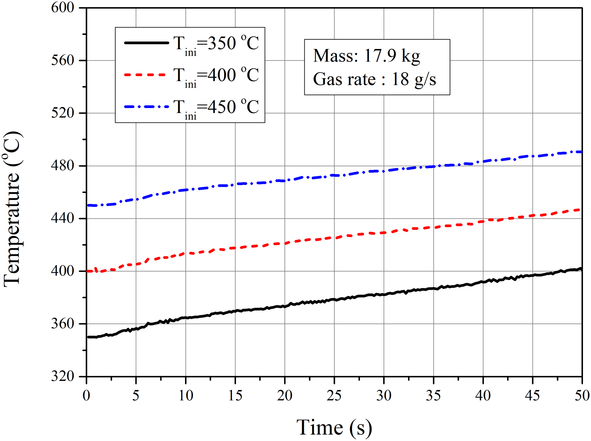
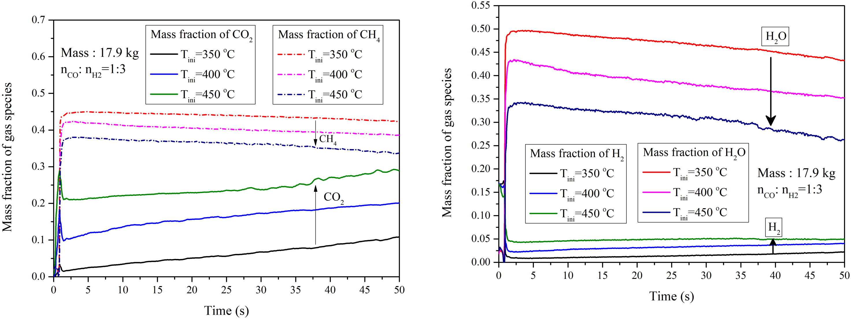
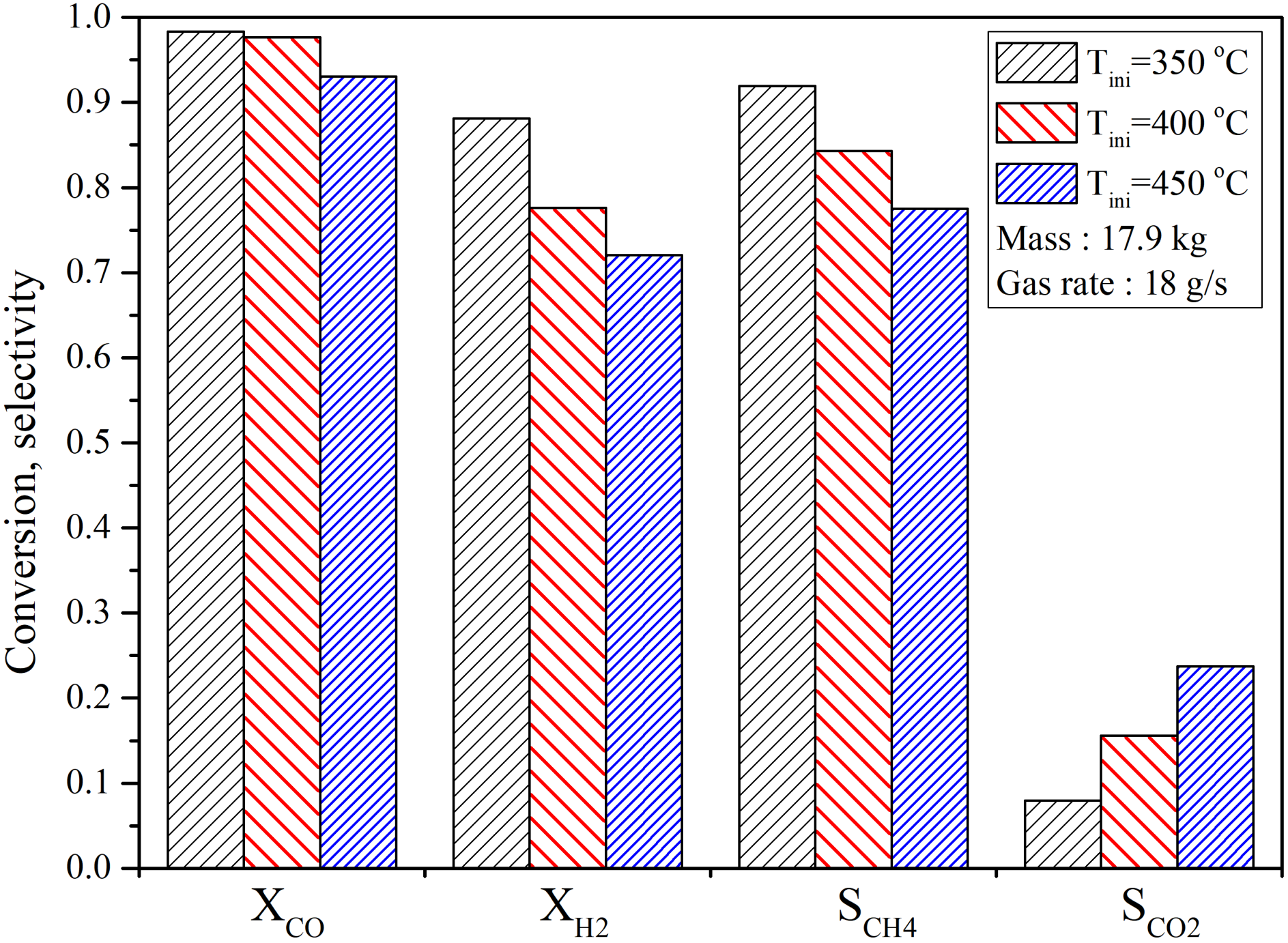
4.2.2. Influence of Initial Temperature

Temperature is the most sensitive parameter for the methanation process, and the influences of the initial temperature are analyzed in this section. Three cases with different initial temperatures, 350 °C, 400 °C and 450 °C, are carried out and compared. The mass inventory and gas inlet rates are 17.9 kg and 0.018 kg/s, respectively. The evolution of temperature at the outlet is shown in Figure 13. For all three cases, the curves of temperature increase with time linearly under the current operating conditions. The case with initial temperature of 350 °C generates the largest temperature increase, 49 °C, while the temperature increase for the case with initial temperature 450 °C is 40 °C. The possible reason is that it is beneficial for improving CO methanation with low temperature, so more CO is consumed for the case with initial temperature 350 °C, and more heat is released.
Figure 14 illustrates the evolution of the mass fraction of gas species at the outlet under different initial temperatures. The arrows in the figures represent the direction of increasing the temperature. It is clear that the increasing of initial temperature leads to the decrease in the products of methane and H2O, but leads to the increase of H2 and CO2. As we know the methanation is the exothermic process. Increasing the temperature will inhibit the forward reaction. Also, raising the temperature increases the reaction rate, while the effect is more effective for the reverse reaction.
The conversion rates and selectivity of gas species are presented in Figure 15. For the current temperature range of temperature, from 350 °C to 450 °C, the conversion rate of CO and H2 decreases with temperature. The methanation reaction is reversed and exothermic. With the increase in temperature, it approaches thermal equilibrium. The reaction proceeds to the reverse reaction, which resultes in the decrease in the conversion of reactants. It illustrates that the reversible reaction is enhanced with increasing temperature. The selectivity of CH4 decreases with temperature, while the selectivity of CO2 increases simultaneously. More reactants are converted into CO2, and we obtain lesser productions of CH4. The temperature should be well controlled in order to guarantee both kinetic rate and production rate. From the simulations and References [9,16,22], the optional temperature should be between 350 °C and 400 °C.

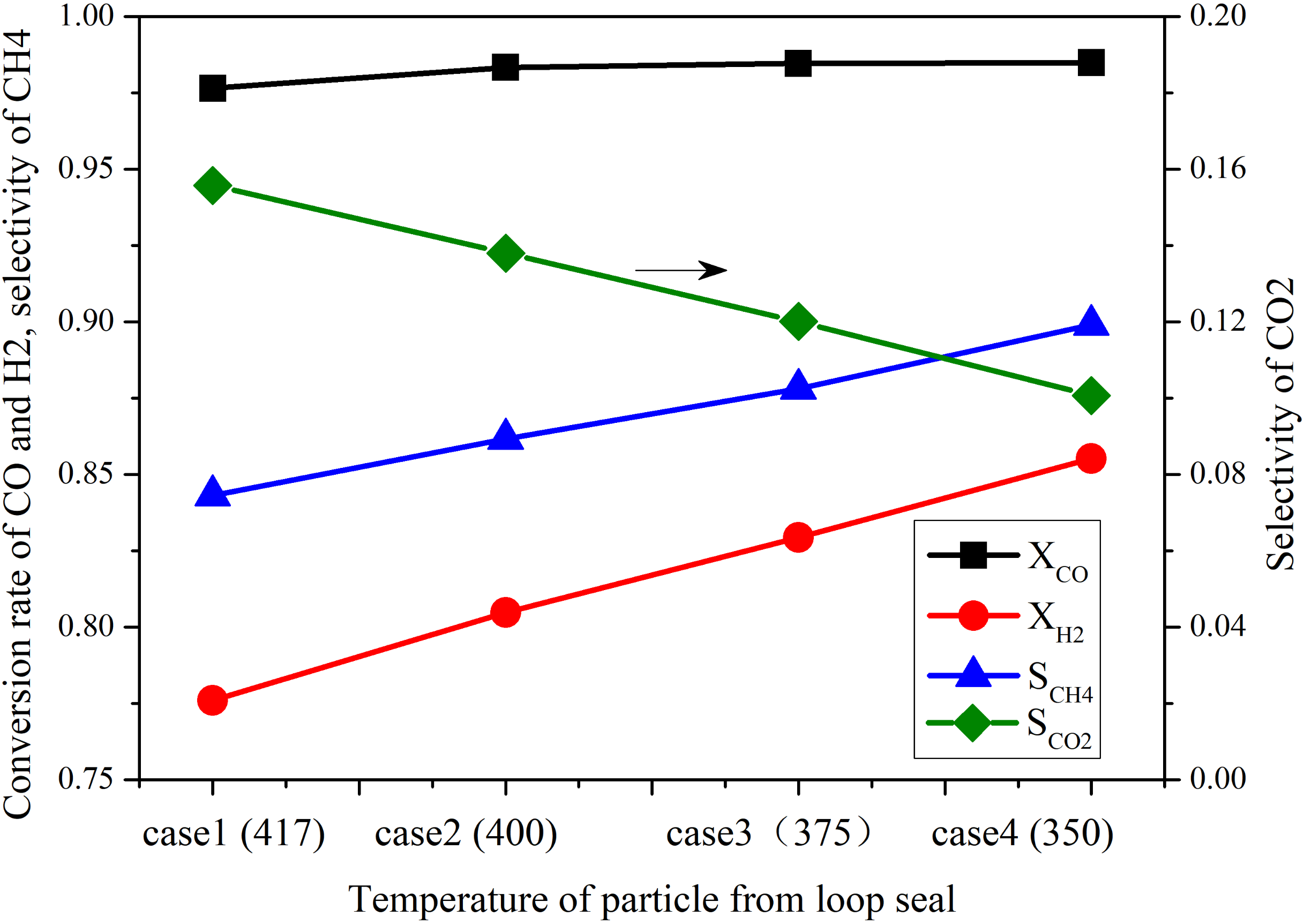
4.2.3. Influence of Cooling Reactor

During fluidization, the particles are separated by the cyclone, and then they enter the bubbling fluidized bed. In this unit, the particles are cooled and then sent back to the reactor via pot seal. The particle flow rate can be controlled by the bubbling fluidized bed and pot seal. The influence of particle flow rate on the evolution of temperature at the outlet is shown in Figure 16. The solid flow rate of ’cold’ particle ranges from 0.17 kg/s to 0.44 kg/s. With the increase in solid flow rate, the temperature at the outlet decreases. In our cases, we have not reached the turning point of the temperature curves. In order to further reduce temperature, the solid flow rate should be continually increased.
By adjusting the cooling efficiency, we can control the temperature of particles in the bubbling fluidized bed. The influence of temperature of particles from the bubbling fluidized bed on the outlet temperature of system is shown in Figure 17. The outlet temperature decreases with the temperature of particles from the bubbling fluidized bed. For the case with T s = 375 °C, we obtain the steady state for thermal conditions, and the outlet temperature remains constant for this case. Due to the fact that the cooling effect counteracts the exothermic effect in the reactor, the system approaches thermodynamic equilibrium. The corresponding evolution of gas species is shown in Figure 18. The mass fraction of each component remains constant, which is quite different from the reference results shown in Figure 7. The performance of the reactor is improved due to the cooling effect of the internal bubbling fluidized bed. The temperature is under control for this case.
The comparison between the conversion rate and selectivity between different cooling effects is shown in Figure 19. Under current operating conditions, the conversion rates of CO and H2 increase with the enhancement of cooling effect. The selectivity of CH4 decreases, and it illustrates that more CH4 are generated. The selectivity of CO2 decreases with the cooling effect, and the water-gas shift reaction is weakened.

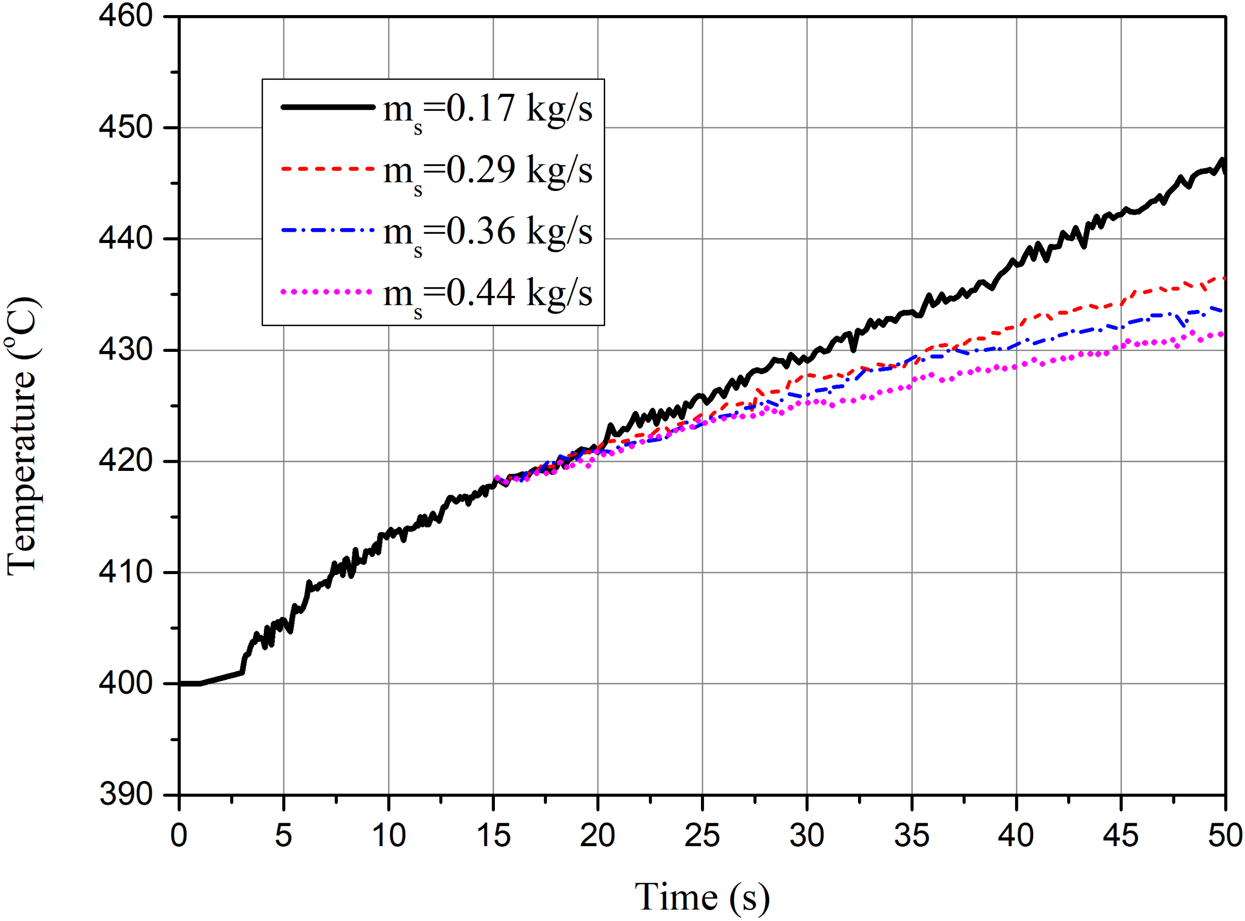
4.2.4. Influence of the Inlet Rate

The mass fractions of gas species at outlet with different inlet rates of CO and H2 are shown in Figure 20. The total gas inlet rate and the ratio between CO and H2 are kept constant and guarantee a similar particle flow behavior. N2, used as balance gas, decreases from 50% to 0, representing the different methane production rates or the different reaction intensities. From the figure, the curves for different cases are nearly identical. In the current operating condition, the inlet rate of CO and H2 has less effect on the performance of the circulating fluidized bed reactor.

5. Conclusions

Three-dimensional numerical simulations of scale-up methanation reactor are carried out using Euler–Euler two-fluid model for better understanding of the methanation process. The production rate of methane increased several times compared with the bench scale reactor. Considering the strong exothermic behavior of methanation process, a circulating fluidized bed reactor was adopted and an inter-connected bubbling fluidized reactor was designed for cooling particles. The flow behavior and reaction characteristics in the scale-up reactor are predicted and studied in this investigation.
The main reactor with variable diameter is designed for guaranteeing the conversion of the reactants and preventing the sinter of catalysts. Reactions finish in the first 15 cm from the inlet, and the residence time of particle is approximately 5 s. The temperature is the essential parameter for methanation reaction, which significantly influences the production of CH4. The simulated results show that the conversion of reactants and the product rate of methane decrease with temperature. The simulated results show that the system with cooling unit reaches the steady state when the temperature of particle from BFB is 375 °C. The results prove the feasibility of scale-up CFB methanation reactor with BFB as the cooling unit, which improves the production rate of methane vastly compared to the bench scale reactor.

Author Contributions

Conceptualization, L.S. and K.L.; methodology, L.S. and K.L.; software, L.S., K.L. and J.F.; validation, L.S., K.L. and J.F.; writing—review and editing, L.S., K.L. and J.F.; supervision, J.F. All authors have read and agreed to the published version of the manuscript.

Funding

This research was funded by National Natural Science Foundation of China (No. 51806192, 51925603) and National Key Research and Development Plan (No. 2017YFE0112500).

Conflicts of Interest

The authors declare no conflict of interest.

Nomenclature

C D Drag coefficient
d s Particle diameter
D s , i j Particle shear tensor
D g s Energy dissipation rate
e c Normal restitution coefficient
gGravity
g 0 Radial distribution function
G k Generation of turbulence kinetic energy
hHeat transfer coefficient
HEnthalpy
IInterphase momentum transfer
J g , i Diffusion flux of species
kTurbulent kinetic energy
k s Conductivity of fluctuating energy
N u Nusselt number
PPressure
P r Prandtl Number
R i j Turbulent-Reynolds stress tensor
R e p Particle Reynolds number
R s , i j Particle kinetic stress tensor
SSource term for enthalpy
TTemperature
u Fluctuating velocity
uVelocity
WMole mass
YMass fraction
Greek letters
α Volume fraction
β Interphase momentum transfer coefficient
ρ Density
μ g Laminar dynamic viscosity
μ s f r Frictional viscosity
Θ g , i j Viscous stress tensor
Θ s , i j Collisional stress tensor
ν g t Turbulent kinematic viscosity
ε Kinetic energy dissipation rate
τ g Stress tensor of gas phase
τ s Stress tensor of gas phase
γ s Dissipation of fluctuation kinetic energy
τ s c Particle collision time
ξ s Solid bulk viscosity
κ Thermal conductivity
ψ g , i Production rate of gas species

References

  1. Seemann, M.C.; Schildhauer, T.J.; Biollaz, S.M.A. Fluidized Bed Methanation of Wood-Derived Producer Gas for the Production of Synthetic Natural Gas. Ind. Eng. Chem. Res. 2010, 49, 7034–7038. [Google Scholar] [CrossRef]
  2. Li, X.; Han, Y.; Huang, Y.; Lin, J.; Pan, X.; Zhao, Z.; Zhou, Y.; Wang, H.; Yang, X.; Wang, A.; et al. Hydrogenated TiO2 supported Ru for selective methanation of CO in practical conditions. Appl. Catal. B Environ. 2021, 298, 120597. [Google Scholar] [CrossRef]
  3. Qin, S.; Li, J.; Long, J.; Yang, X.; Miao, P. Promotion Effect of Cerium on Mo/Al2O3 Catalyst for Methanation. Appl. Catal. A Gen. 2020, 598, 117559. [Google Scholar] [CrossRef]
  4. Gao, W.; Meng, X.; Jin, D.; Xu, B.; Dai, W.; Zhao, R.; Xin, Z. Polyol-pretreated SBA-16 supported Ni-Fe bimetallic catalyst applied in CO methanation at low temperature. Mol. Catal. 2021, 512, 111769. [Google Scholar] [CrossRef]
  5. Xiao, Y.S.; Song, Y.H.; Luo, Q.X.; Shi, X.Y.; Li, J.; Hao, Q.Q.; Liu, Z.T.; Liu, Z.W. Kinetics behavior of Co/Ni-ordered mesoporous alumina for the CO methanation. Chem. Eng. Sci. X 2021, 10, 100094. [Google Scholar]
  6. Mohanty, U.S.; Ali, M.; Azhar, M.R.; Al-Yaseri, A.; Keshavarz, A.; Iglauer, S. Current advances in syngas (CO + H2) production through bi-reforming of methane using various catalysts: A review. Int. J. Hydrogen Energy 2021, 46, 32809–32845. [Google Scholar] [CrossRef]
  7. Zhang, Q.; Guo, X.; Yao, X.; Cao, Z.; Sha, Y.; Chen, B.; Zhou, H. Modeling, simulation, and systematic analysis of high-temperature adiabatic fixed-bed process of CO methanation with novel catalysts. Appl. Energy 2020, 279, 115822. [Google Scholar] [CrossRef]
  8. Kopyscinski, J.; Schildhauer, T.J.; Biollaz, S.M. Methanation in a fluidized bed reactor with high initial CO partial pressure: Part II—Modeling and sensitivity study. Chem. Eng. Sci. 2011, 66, 1612–1621. [Google Scholar] [CrossRef]
  9. Kopyscinski, J.; Schildhauer, T.J.; Biollaz, S.M. Methanation in a fluidized bed reactor with high initial CO partial pressure: Part I—Experimental investigation of hydrodynamics, mass transfer effects, and carbon deposition. Chem. Eng. Sci. 2011, 66, 924–934. [Google Scholar] [CrossRef]
  10. Kopyscinski, J.; Schildhauer, T.J.; Biollaz, S.M.A. Fluidized-Bed Methanation: Interaction between Kinetics and Mass Transfer. Ind. Eng. Chem. Res. 2011, 50, 2781–2790. [Google Scholar] [CrossRef]
  11. Li, J.; Yang, B. A Multi-scale Model for the Simulation of Bubbling Fluidized Bed Methanation. In Proceedings of the 25th International Symposium on Chemical Reaction Engineering, Florence, Italy, 20–23 May 2018. [Google Scholar]
  12. Yu, H.; Zhang, H.; Buahom, P.; Liu, J.; Xia, X.; Park, C.B. Prediction of thermal conductivity of micro/nano porous dielectric materials: Theoretical model and impact factors. Energy 2021, 233, 121140. [Google Scholar] [CrossRef]
  13. Kopyscinski, J.; Schildhauer, T.J.; Vogel, F.; Biollaz, S.M.; Wokaun, A. Applying spatially resolved concentration and temperature measurements in a catalytic plate reactor for the kinetic study of CO methanation. J. Catal. 2010, 271, 262–279. [Google Scholar] [CrossRef]
  14. Kopyscinski, J.; Schildhauer, T.J.; Biollaz, S.M.A. Employing Catalyst Fluidization to Enable Carbon Management in the Synthetic Natural Gas Production from Biomass. Chem. Eng. Technol. 2009, 32, 343–347. [Google Scholar] [CrossRef]
  15. Li, J.; Yang, B. Bubbling fluidized bed methanation study with resolving the mesoscale structure effects. AIChE J. 2019, 65, 16561. [Google Scholar] [CrossRef]
  16. Liu, Y.; Hinrichsen, O. CFD Simulation of Hydrodynamics and Methanation Reactions in a Fluidized-Bed Reactor for the Production of Synthetic Natural Gas. Ind. Eng. Chem. Res. 2014, 53, 9348–9356. [Google Scholar] [CrossRef]
  17. Chein, R.Y.; Yu, C.T.; Wang, C.C. Numerical simulation on the effect of operating conditions and syngas compositions for synthetic natural gas production via methanation reaction. Fuel 2016, 185, 394–409. [Google Scholar] [CrossRef]
  18. Gidaspow, D. Multiphase Flow and Fluidization: Continuum and Kinetic Theory Descriptions; Academic Press: Cambridge, MA, USA, 1994. [Google Scholar]
  19. Wang, S.; Wang, Q.; Chen, J.; Liu, G.; Lu, H.; Sun, L. Extension of cluster-structure dependent drag model to simulation of riser with Geldart B particles. Adv. Powder Technol. 2016, 27, 57–63. [Google Scholar] [CrossRef]
  20. Liu, J.; Shen, W.; Cui, D.; Yu, J.; Su, F.; Xu, G. Syngas methanation for substitute natural gas over Ni–Mg/Al2O3 catalyst in fixed and fluidized bed reactors. Catal. Commun. 2013, 38, 35–39. [Google Scholar] [CrossRef]
  21. Sun, L.; Luo, K.; Fan, J. Production of synthetic natural gas by CO methanation over Ni/Al2O3 catalyst in fluidized bed reactor. Catal. Commun. 2018, 105, 37–42. [Google Scholar] [CrossRef]
  22. Sun, L.; Luo, K.; Fan, J. Numerical Simulation of CO Methanation for the Production of Synthetic Natural Gas in a Fluidized Bed Reactor. Energy Fuels 2017, 31, 10267–10273. [Google Scholar] [CrossRef]
Figure 1. Profile of gas species concentration along height with 70 g and 100 g catalyst. Line: simulated results; scatter: experimental measurement.
Energies 14 07095 g001
Figure 2. Numerical results of instantaneous distribution of gas species mass fraction. N2 is used as a balance gas. The mass of catalyst is 70 g.
Energies 14 07095 g002
Figure 3. Expanded bed height of the solid phase under different solid inventory.
Energies 14 07095 g003
Figure 4. Geometry of the circulated fluidized bed reactor: (1) main reactor; (2) riser; (3) cyclone; (4) bubbling fluidized bed; and (5) pot-seal.
Energies 14 07095 g004
Figure 5. Instantaneous solid volume fraction at different time.
Energies 14 07095 g005
Figure 6. Distribution of time-averaged relative pressure along with height.
Energies 14 07095 g006
Figure 7. Time-evolution of mass fraction of gas species at outlet. Initial temperature is 400 °C. Gas inlet rate is 0.018 kg/s. Solid inventory is 17.9 kg.
Energies 14 07095 g007
Figure 8. Time evolution of temperature at the outlet of reactor. Initial temperature is 400 °C. Gas inlet rate is 0.018 kg/s. Solid inventory is 17.9 kg.
Energies 14 07095 g008
Figure 9. Contours of mass fraction of gas species. N2 is used as balance gas. Temperature is 400 °C.
Energies 14 07095 g009
Figure 10. Time-evolution of solid flux of riser. Initial temperature is 400 °C. Gas inlet rate is 1.8 g/s. Solid inventory is 17.9 kg.
Energies 14 07095 g010
Figure 11. Left: The distribution of time-averaged axial velocity of gas and solid phases. Right: The distribution of time-averaged solid volume fraction.
Energies 14 07095 g011
Figure 12. Profile of drag coefficient versus solid volume fraction.
Energies 14 07095 g012
Figure 13. Profile of time evolution of gas temperature with different initial condition.
Energies 14 07095 g013
Figure 14. Time-evolution of gas species mass fraction under different temperatures. Gas inlet rate is 0.018 kg/s. Solid inventory is 17.9 kg.
Energies 14 07095 g014
Figure 15. Profile of conversion and selectivity under different initial temperature.
Energies 14 07095 g015
Figure 16. Profile of time-averaged gas and solid vertical velocity.
Energies 14 07095 g016
Figure 17. Profile of time evolution of temperature under different cooling effect of internal bubbling fluidized bed reactor.
Energies 14 07095 g017
Figure 18. Profile of time-averaged gas species mass fraction with mass flow rate 0.44 kg/s. Temperature of bulling fluidized bed is 375 °C. N2 is used as balance gas.
Energies 14 07095 g018
Figure 19. Conversion rate and selectivity under different cooling effect.
Energies 14 07095 g019
Figure 20. Time evolution of gas species mass fraction under different temperatures. Gas inlet rate is 0.018 kg/s. Solid inventory is 17.9 kg. N2 is used as balance gas.
Energies 14 07095 g020
Table 1. Conservation equations.
Stress tensors
τ g = μ g [ u g + ( u g ) T ] 2 3 μ g ( · u g ) I
τ s = μ s [ u s + ( u s ) T ] ( λ s 2 3 μ s ) ( · u s ) I
Solid pressure for KTGF
p s = α s ρ s θ + 2 ρ s ( 1 + e ) α s 2 g 0 θ
Conductivity of fluctuating energy
k s = 25 ρ s d s π θ 64 ( 1 + e ) g 0 1 + 6 5 ( 1 + e ) g s α s 2 + 2 α s 2 ρ s d s g 0 ( 1 + e ) ( θ π ) 1 / 2
Radial distribution function
g 0 = 1 α s α s , m a x 1 / 3 1
Dissipation of fluctuation kinetic energy
γ s = 1 3 ( 1 e 2 ) 3 2 θ τ s c
Particle collision time
τ s c = 6 α s g 0 d s 16 π θ
Energy dissipation rate
D g s = d s ρ s 4 π θ g 0 18 μ g d s 2 ρ s 2 | u g u s | 2
Solid shear viscosity
μ s = 4 5 α s 2 ρ s d s g 0 ( 1 + e ) θ π + 10 ρ s d s π θ 96 ( 1 + e ) α s g 0 1 + 4 5 g 0 α s ( 1 + e ) 2
Solid bulk viscosity
ξ s = 4 3 α s 2 ρ s d s g 0 ( 1 + e ) θ π 1 / 2
Heat transfer coefficient
h = 6 α s α g λ g N u d p 2
Nusselt number
N u = ( 7 10 α g + 5 α g 2 ) ( 1 + 0.7 R e 0.2 P r 1 / 3 ) + ( 1.33 2.4 α g + 1.2 α g 2 ) R e 0.7 P r 1 / 3
Prandtl Number
P r = μ g C g λ g
Generation of turbulence kinetic energy
G k = μ t u g · [ u g + u g T ] 2 3 u g ( μ t u g + ρ g k )
Gas phase shear viscosity
μ g = C μ k 2 ε
Table 2. Kinetic parameter for the calculation of reaction rate [9,17].
ParameterAUnitEUnit
k 1 3.711 × 10 17 mol · s 1 kg c a t 1 Pa 0.5 240,100J/mol
k 2 5.431mol · s 1 kg c a t 1 Pa 0.5 67,130J/mol
K e q , 1 1.198 × 10²³Pa226,830J/mol
K e q , 2 1.767 × 10 2 −4400J/mol
K C H 4 6.65 × 10 9 Pa 1 −38,280J/mol
K C O 8.23 × 10 10 Pa 1 −70,650J/mol
K H 2 6.12 × 10 14 Pa 1 −82,900J/mol
K H 2 O 1.77 × 10 5 88,680J/mol
Publisher’s Note: MDPI stays neutral with regard to jurisdictional claims in published maps and institutional affiliations.

