Article

Experimental Study of the Air Side Performance of Fin-and-Tube Heat Exchanger with Different Fin Material in Dehumidifying Conditions

1
School of Environmental and Municipal Engineering, Lanzhou Jiaotong University, Lanzhou 730070, China
2
Key Laboratory of Railway Vehicle Thermal Engineering, Lanzhou Jiaotong University, Ministry of Education of China, Lanzhou 730070, China
3
Key Laboratory of Yellow River Water Environment in Gansu Province, Lanzhou 730070, China
*
Author to whom correspondence should be addressed.
Energies 2021, 14(21), 7030; https://doi.org/10.3390/en14217030
Submission received: 10 October 2021 / Revised: 24 October 2021 / Accepted: 26 October 2021 / Published: 27 October 2021
(This article belongs to the Section J: Thermal Management)

Abstract

:
Under dehumidifying conditions, the condensed water will directly affect the heat transfer and resistance characteristics of a fin-and-tube heat exchanger. The geometrical form of condensed water on fin surfaces of three different fin materials (i.e., copper fin, aluminum fin, and aluminum fin with hydrophilic layer) in a fin-and-circular-tube heat exchanger was experimentally studied in this paper. The effect of the three different fin materials on heat transfer and friction performance of the heat exchanger was researched, too. The results show that the condensation state on the surface of copper fin and aluminum fin are dropwise condensation. The condensation state on the surface of the aluminum fin with the hydrophilic layer is film condensation. For the three different material fins, increasing the air velocity (ua,in) and relative humidity (RHin) of the inlet air can enhance the heat transfer of the heat exchanger. Friction factor (f) of the three different material fins decreases with the increase of ua,in, however, increases with the increase of RHin. At the same ua,in or RHin, Nusselt number (Nu) of the copper fin heat exchanger is the largest and Nu of the aluminum fin with hydrophilic layer is the smallest, f of the aluminum fin heat exchanger is the largest and f of the aluminum fin with hydrophilic layer is the smallest. Under the identical pumping power constrain, the comprehensive heat transfer performance of the copper fin heat exchanger is the best for the studied cases.

1. Introduction

Fin-and-tube heat exchanger (FTHE) is a common structural form of a heat exchanger. The heat transfer between the cold and hot fluid is carried out, the refrigerant is in the tube, and the air is outside the tube. This type of heat exchanger has the characteristics of simple structure, easy processing, and assembly and is widely used in the petrochemical industry, aviation, vehicle, power machinery, air conditioning, refrigeration, etc. [1,2,3,4]. When the fin surface temperature of the FTHE is lower than the dew point temperature of the airflow through the heat exchanger, the moisture in the air will be condensed on the fin surface. Thus, heat and mass transfer occur simultaneously during the process of dehumidification [5].
The condensed water will not only directly affect the characteristics of heat transfer and pressure drop of the FTHE but also provide a humid environment for the growth of bacteria and microorganisms, which will cause corrosion to the heat exchanger and bring a series of health problems. Therefore, it is necessary to study the heat transfer and resistance performances of the FTHE under the conditions of dehumidification, as well as the condensation and movement characteristics of the condensed water.
Many pieces of research have been carried out on the characteristics of pressure drop and heat transfer of the FTHE under dehumidifying conditions. Wang et al. [6,7] studied the heat and mass transfer characteristics of plate FTHEs in dry and wet conditions. Jang et al. [8] experimentally analyzed the heat transfer and fluid flow characteristics of a four-row circle FTHE under wet and dry conditions. Ma et al. [9,10] carried out a large number of experimental studies on heat exchangers with various enhanced fin structures, such as slit fin, corrugated fin, and louver fin with a hydrophilic layer. They analyzed the air-side heat mass transfer characteristics and pressure drop characteristics of FTHE with a hydrophilic layer under dehumidification conditions. Phan et al. [11] investigated the effect of fin pitch, tube row, and inlet air humidity on air-side heat mass transfer performance of louvered FTHEs under wet conditions. Heat transfer and friction characteristics of the louver-finned heat exchangers and radial slit-finned heat exchangers under wet conditions were experimentally investigated by Kim [12]. Howongsakun et al. [13] demonstrated the effects of highly moist inlet air conditions on the value of the Lewis number in a fin-and-tube cooling coil. Pirompugd and Wongwises [14] presented the equivalent dry-bulb temperature method and actual dry-bulb temperature method to estimate the characteristics of wavy FTHEs under partly and fully wet conditions. Li et al. [15] numerically analyzed the heat mass transfer of a five-row FTHE under wet conditions. The distributions of vapor condensation mass rate for both fin and tube surfaces were obtained. Zhang et al. [16] reviewed the experimental investigations from articles conducted over the last few decades on the heat transfer performances of FTHEs under partially and fully wet conditions. Hazarika et al. [17] designed a novel fork-shaped fin array attached to a circular tube and studied the thermo-heightened performance under fully wet conditions. Liu et al. [18] investigated experimentally the influence of operating parameters on the heat transfer performance of a minichannel heat exchanger used as evaporators under wet conditions. Zhan et al. [19] developed a numerical model for analyzing the dusty particle deposition on wet fin-surfaces in practical working processes. Zhang et al. [20] established a 3D model taking gas-liquid interfacial friction force into consideration to study counter-current and co-current gas-liquid falling film flow characteristics on the air side of the FTHE with a typical large fin pitch. Nguyen and Nguyen [21] investigated the effects of the air velocity, water temperature, and water flow rate on the cooling load and air pressure drop of a dehumidifying air coil with a continuous plate fin-and-tube. An experimental study for air-side thermal-hydraulic performance of a louvered FTHE under wet conditions was performed by Ayad et al. [22].
Although many research about the air side performances of FTHE under dehumidification conditions were investigated by domestic and foreign scholars, there are few experimental studies on the performance of heat exchanger based on different fin materials. The geometrical form of condensed water on the fin surfaces of fin-and-circular-tube heat exchanger with three different fin materials and the influence of fin materials on heat transfer and resistance are studied by experimental test in this paper. The experimental results can not only improve the understanding of the heat transfer and resistance performance mechanism of heat exchangers but also provide the basis for the optimal design of FTHEs under dehumidifying conditions.

2. Materials and Methods

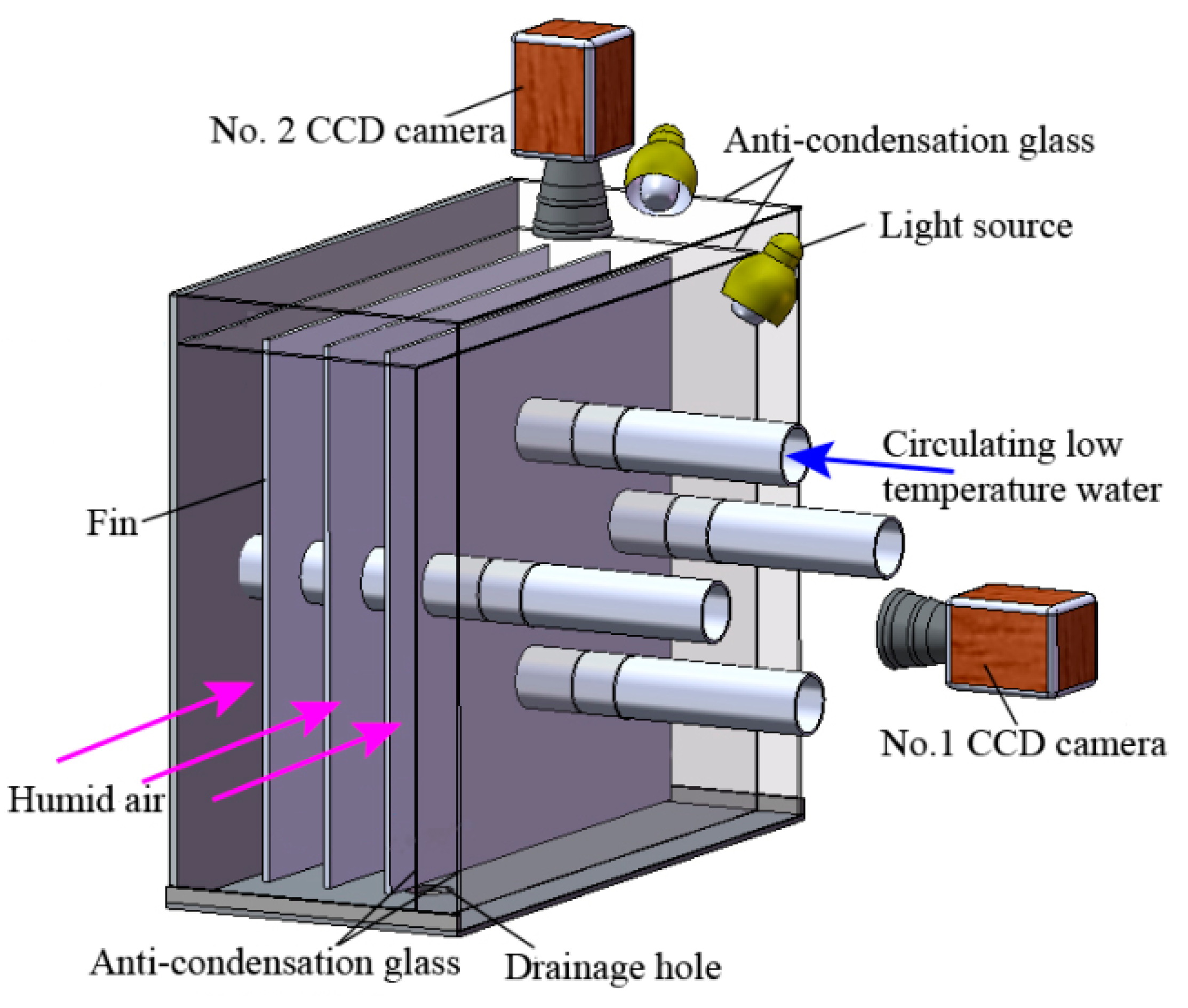
2.1. Experimental Apparatus

The experimental system used in this paper is shown in Figure 1. The experimental system mainly includes a moist air handling system, low temperature circulating water system, and visual data acquisition system.
The moist air handling system is a closed-circuit type wind tunnel that circulates the moist air. The stable and uniform airflow can be provided to flow through the FTHE under the given conditions of relative humidity, inlet temperature, and inlet air velocity. The moist air handling system comprises 7 parts: variable speed centrifugal fan, flow equalization board, grading ring, mixer, nozzles, electrode humidifier, and electric heater. The variable speed centrifugal fan can provide the circulating air for the experimental test system. The electrode humidifier was used to control the relative humidity of the inlet air. The temperature of the inlet air was monitored using a dry-bulb thermometer and the air was heated by an electric heater. The nozzles chamber based on ASHRAE41.2 standard [23] was used to measure the airflow rate. Two pressure difference transducers with a ±3.0 Pa precision were used to measure the pressure differences across the nozzles and the heat exchangers, respectively. The grading ring, which connects the four static pressure holes of the same section through an organic plastic tube and plays a role in stabilizing the pressure of the test section, was connected with the corresponding pressure difference transducer. The precisions of the dry and wet bulb temperature transducer and humidity transducer were ±0.2 °C and ±2%, respectively.
The test section was the core of the whole experimental system. In order to ensure the uniformity and stability of the airflow, a flow equalization board, a grading ring, and a mixer were, respectively, installed at the inlet and outlet of the test section. The test heat exchangers were made of copper tubes and 3 fin materials (copper fin, aluminum fin, and aluminum fin with hydrophilic layer). The photos of test specimens with 3 different fin materials are given in Figure 2. Their detailed configurations are tabulated in Table 1.
The visual data acquisition system is the brain of the whole experimental test system, collecting all kinds of experimental data. In order to observe the geometry, condensation position, formation, growth, and movement characteristics of condensation water on the fin surface, 2 cameras were, respectively, placed on the side and top of the heat exchanger, as shown in Figure 3. Two T-type thermocouples were used to measure the water temperature difference between the inlet and outlet of the heat exchanger. A total of 9 T-type thermocouples were arranged on the fin surface of the heat exchanger to measure the fin surface temperature. All the thermocouples were calibrated with an accuracy of ±0.2 °C.
The low temperature circulating water system was used to control the inlet temperature of circulating water into the test heat exchangers.

2.2. Data Processing Method

The data processing method used in this paper was the Threlkeld method [24] and ASHRAE41.2 standard [23].
Heat   transfer   of   air   side :   Q a = m a ( i a , in i a , out )
Heat   transfer   of   water   side :   Q w = m w c p , w ( T w , out T w , in )
The   average   heat   transfer   rate :   Q ave = ( Q a + Q w ) / 2
The   overall   surface   efficiency :   η 0 = ( A tc + A af η f , wet ) / A 0
where A tc is the outside surface area of tubes, A af is the fin surface area, η f , wet is the wet fin efficiency obtained according to the method from Liang et al. [25], A 0 is the total air side surface area.
Thus, the air side sensible heat transfer coefficient is
h s = Q ave / { η 0 A 0 [ ( T a T fb ) + i fg c p , a L e 2 / 3 ( d a d fb ) ] }
The   overall   average   N u   is   defined   by :   N u = h s d e / λ
The   equivalent   diameter   of   the   air   side   is   defined   by :   d e = 4 A min L x / A 0
where de is the equivalent diameter of the air side, A min is the minimum free flow area of the heat exchanger, Lx is the fin length along the air flow direction.
The friction factor of the air side, according to Kays and London [26], is defined as:
f = ( A min A 0 ) ( ρ m ρ in ) [ 2 Δ P ρ in G 2 ( 1 + σ 2 ) ( ρ in ρ out 1 ) ]
where σ = A min / A fr , G = m a / A min , A fr is the frontal area of the heat exchanger, G is the mass flow of air at the minimum free flow area.
Under identical pumping power constrain, JF (i.e., thermal performance factor) is used to evaluate comprehensive heat transfer performance of the three different fin material cases, which is defined as:
J F = ( N u / N u Al , f ) / ( f / f Al , f ) 1 / 3

3. Results

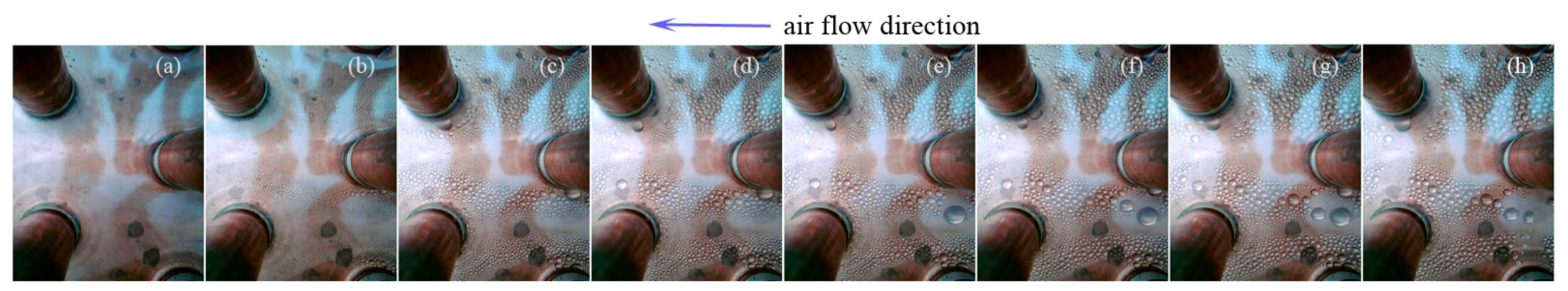
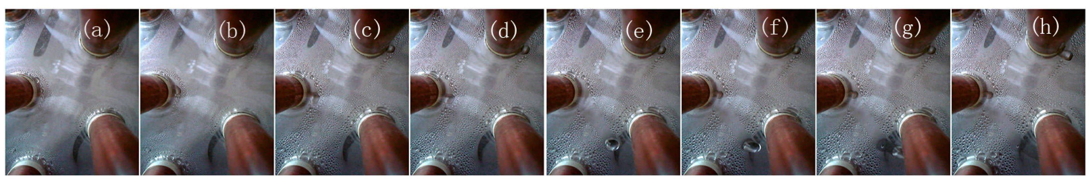
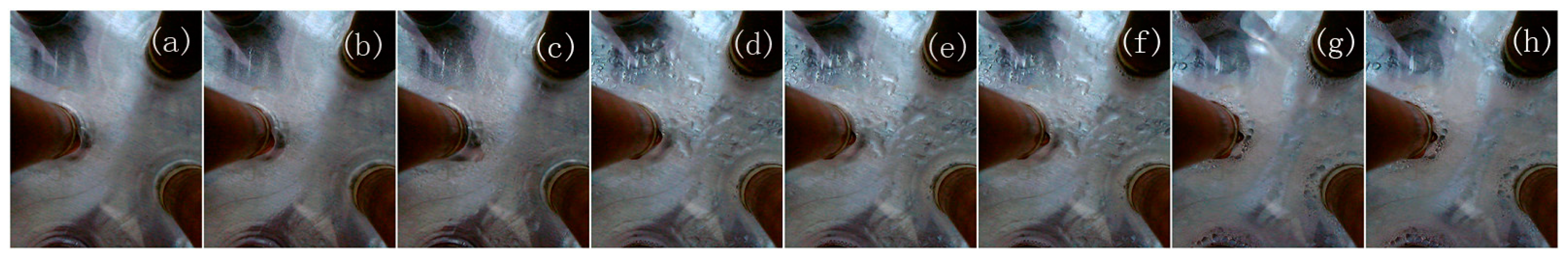
3.1. Geometry Form and Movement Characteristics of Condensate Water on the Fin Surface

Figure 4, Figure 5 and Figure 6 show the geometry form and movement characteristics of condensed water on the fin surfaces of three FTHEs with different fin material at τ = 0–300 s under the conditions of RHin = 50%, Ta,in = 27 °C, Tw,in = 12 °C, ua,in = 2.0 m/s. The geometry form and movement characteristics of condensate droplets on the copper fin surface are given in Figure 4. It can be seen that with the start-up of the fan, the air flows through the heat exchanger, the vapor in the air gradually condenses into tiny droplets on the fin surface near the circular tubes (as shown in Figure 4a,b). With the increase of ventilation time, the size and quantity of condensed droplets increase gradually (as shown in Figure 4c). Moreover, with the increase of the volume of condensation droplets, some adjacent droplets gradually merge into large droplets (as shown in Figure 4d). With the continuous condensation, the volume of the condensed droplets increases further. If the adhesion force of the condensate droplet to the fins is larger than the resultant force of the drag force produced by the airflow and the gravity of the condensate droplet, the condensed droplet will still adhere to the fin surface perfectly and gradually form a flat hemispherical shape. When the adhesion force of the condensate droplet to the fins is smaller than the resultant force of the drag force produced by the airflow and the gravity of the condensate droplet, the condensate droplet will slide on the fin surface. In the process of sliding, the condensate will merge with some other condensate droplets and discharge from the fin together (as shown in Figure 4e–h). The condensate water will continue to condense on the fin surface, then merge and discharge.
The geometry form and movement characteristics of condensate droplets on the aluminum fin surfaces are shown in Figure 5. Comparing Figure 4 with Figure 5, we can see that the condensation process of condensate droplets on the copper fin surface and aluminum fin surface is similar. They are all dropwise condensation, and they all experience the process of nucleation, growth, coalescence, and discharge from the fin surface. The difference is that the size of condensate droplets on the copper fin surface is generally larger than that on the aluminum fin surface.
Figure 6 shows the geometry form and movement characteristics of condensed water on the surface of the aluminum fin with a hydrophilic layer. It can be seen from Figure 6a–c that with the air flowing through the heat exchanger, the condensate water on the surface of the aluminum fin with hydrophilic layer firstly appears near the circular tubes and presents film condensation. With the increase of ventilation time, the size of tiny condensate film gradually increases and merges with the adjacent condensate film (as shown in Figure 6d,e). Moreover, the thickness of condensate film increases gradually. When the resultant force of the drag force produced by the airflow and the gravity of the condensate film is larger than the adhesion force of the condensate film to the fins, the condensate film will slide down the fin surface. In the process of sliding down, it will gradually merge with other condensation films and discharge the fin together (as shown in Figure 6f–h). Then, the next cycle of the condensation process will be carried out.

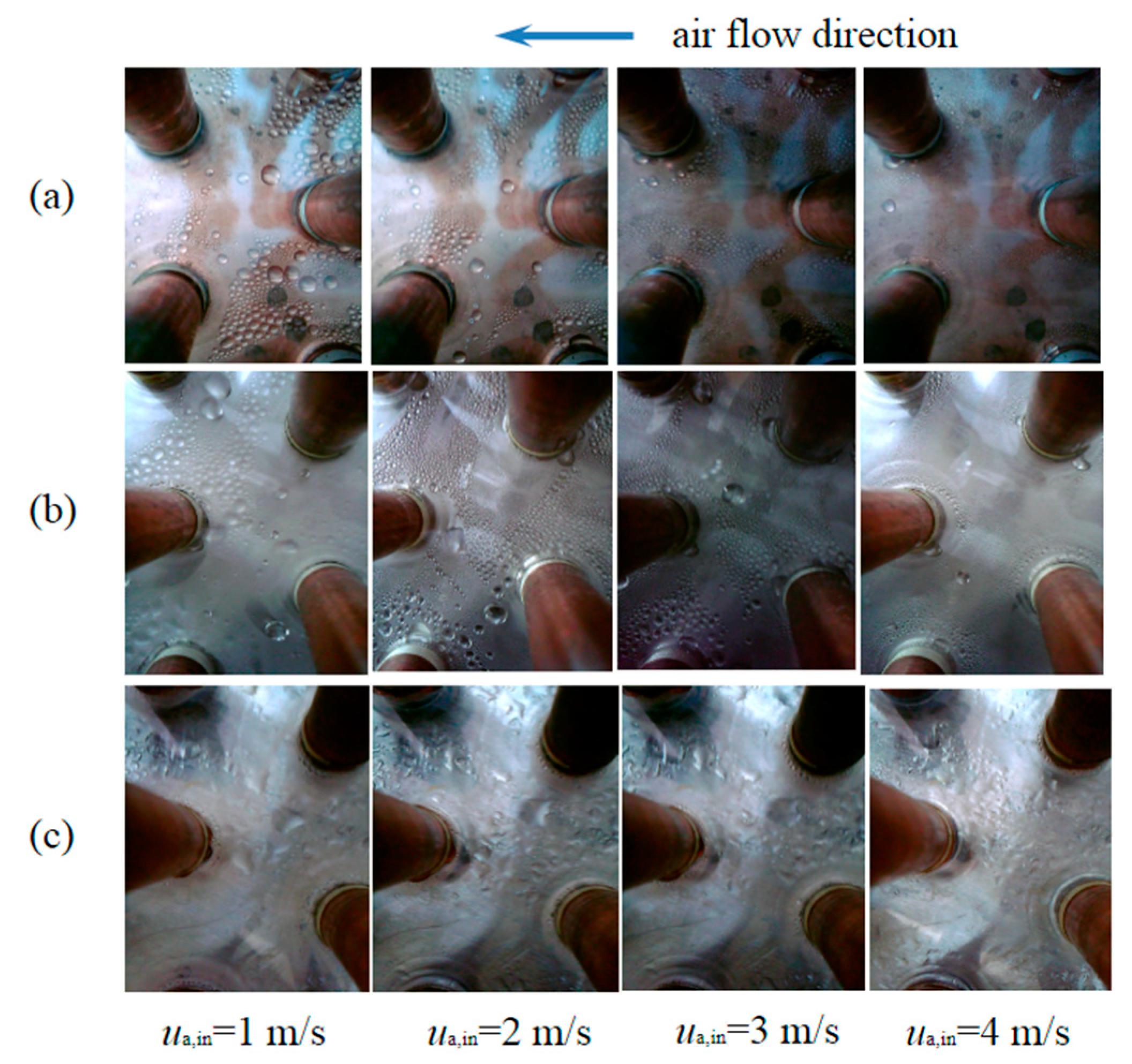
3.2. The Effect of ua,in and RHin on the Geometry Form of Condensate Water on the Fin Surfaces

Figure 7 shows the geometry form of condensate water on the fin surfaces of three different materials under different air inlet velocities (ua,in) at τ = 300 s, RHin = 50%, Ta,in = 27 °C, Tw,in = 12 °C. It can be found that the condensate droplets on the copper fin surface and aluminum fin surface are dropwise condensation. However, the condensate water on the aluminum fin with the hydrophilic layer is film condensation. In addition, we can see that with increasing of ua,in, the diameter of condensate water distributed on the fin surfaces of three different materials all gradually decrease. Especially when the air inlet velocity reaches 4 m/s, there is almost no large-diameter condensate water on the fin surfaces. This is because, with the increase of ua,in, the drag force acting on the surface of the condensate water increases, the combined force of drag force and gravity will increase, the condensate water with a larger diameter will be quickly discharged from the fin surface.
The effect of air inlet relative humidity (RHin) on the geometry form of condensate water on the fin surfaces of three different materials at τ = 300 s, ua,in = 2 m/s, Ta,in = 27 °C, Tw,in = 12 °C is given in Figure 8. It can be seen from Figure 8a,b that with the changing of RHin, the condensation and movement characteristics of the condensation droplets on the surfaces of copper fin and aluminum fin are similar. When RHin = 40%, there are many condensate droplets on the surfaces of copper fin and aluminum fin, and they are evenly distributed on the fin surfaces. When RHin increases from 50% to 70%, the number of condensate droplets on the surfaces of copper fin and aluminum fin all decrease. Moreover, when RHin reaches 80%, there are almost no condensate droplets on the surfaces of copper fin and aluminum fin. This is because when RHin is very large, the condensation rate is very fast, the condensate droplets will be quickly discharged from the fin surfaces. For the aluminum fin with a hydrophilic layer, as shown in Figure 8c, with the increase of RHin, the thickness of condensation film becomes thinner, and the distribution of condensate film on the fin surface is more uniform. This also shows that with the increase of RHin, the condensation rate is accelerated. The thicker condensate film will be quickly discharged from the surface of the aluminum fin with a hydrophilic layer.

3.3. The Effect of Ta,in on Nu and f of Heat Exchanger

Figure 9 shows the effect of air inlet temperature Ta,in on Nu and f of three different fin materials at RHin = 50%, Tw,in = 12 °C and ua,in = 0.5 m/s–4.0 m/s. For the copper fin heat exchanger, it can be found in Figure 9a that Nu of the three different Ta,in (20 °C, 27 °C, and 35 °C) all increase with increasing ua,in. Under the same air inlet velocity, Nu of Ta,in = 35 °C is the largest, and then gradually decreases with the decrease of Ta,in. The differences of Nu between Ta,in = 35 °C and 27 °C is larger than that between Ta,in = 27 °C and 20 °C. When ua,in ranges from 0.5 m/s to 4.0 m/s, comparing with the case of Ta,in = 20 °C, Nu of Ta,in = 27 °C increases about 0.06–0.15 times, however Nu of Ta,in = 35 °C increases about 0.30~0.73 times compared with that of Ta,in = 27 °C. As shown in Figure 9b, f decreases with the increase of ua,in. At the same ua,in, f of Ta,in = 20 °C is the smallest and f increases with increasing Ta,in. The differences of f between Ta,in = 35 °C and 27 °C is larger than that between Ta,in = 27 °C and 20 °C. When ua,in ranges from 0.5 m/s to 4.0 m/s, comparing with the case of Ta,in = 20 °C, f of Ta,in = 27 °C increases about 0.02–0.05 times, f of Ta,in = 35 °C increases about 0.34–0.54 times compared with that of Ta,in = 27 °C. This shows that increasing the air inlet temperature will not only improve the heat transfer performance of the heat exchanger but also increase the flow resistance.
For the aluminum fin case, as shown in Figure 9c,d and aluminum fin with hydrophilic layer case as shown in Figure 9e,f, the similar trends of the effect of Ta,in on Nu and f can be observed. Just the differences of Nu and f of the aluminum fin with a hydrophilic layer between Ta,in = 27 °C and 20 °C is not obvious.

3.4. The Effect of Tw,in on Nu and f of Heat Exchanger

The effect of water inlet temperature Tw,in on Nu and f of three different fin materials at RHin = 50%, Ta,in = 27 °C and ua,in = 0.5 m/s–4.0 m/s are shown in Figure 10. It can be seen from Figure 10a,b that Nu of the three different Tw,in (12 °C, 15 °C, and 18 °C) all increase with increasing ua,in, however, f all decrease with increasing ua,in. Under the same air inlet velocity, Nu of Tw,in = 18 °C is the largest, and then gradually decreases with decreasing of Tw,in. The differences of Nu between Tw,in = 15 °C and 12 °C is larger than that between Tw,in = 15 °C and 18 °C. When ua,in ranges from 0.5 m/s to 4.0 m/s, comparing with the case of Tw,in = 12 °C, Nu of Tw,in = 15 °C increases about 0.16–0.75 times, however Nu of Tw,in = 18 °C increases about 0.01–0.1 times compared with that of Tw,in = 15 °C. At the same ua,in, f of Tw,in = 12 °C is the largest and f decreases with increasing Tw,in, however, the differences of the three different Tw,in are not obvious. This shows that the heat transfer performance of the copper fin heat exchanger can be improved by increasing the water inlet temperature. The reason is that when the water inlet temperature is low, the quantity of condensate generated on the fin surface will increase; at the same inlet air velocity, the thickness of condensate will increase. The purpose of destroying the airflow boundary layer cannot be achieved thus that the heat transfer capacity is weakened, and the pressure drop is increased.
For the aluminum fin and aluminum fin with hydrophilic layer cases, similar trends of the effect of Tw,in on Nu and f are observed in Figure 10c–f.

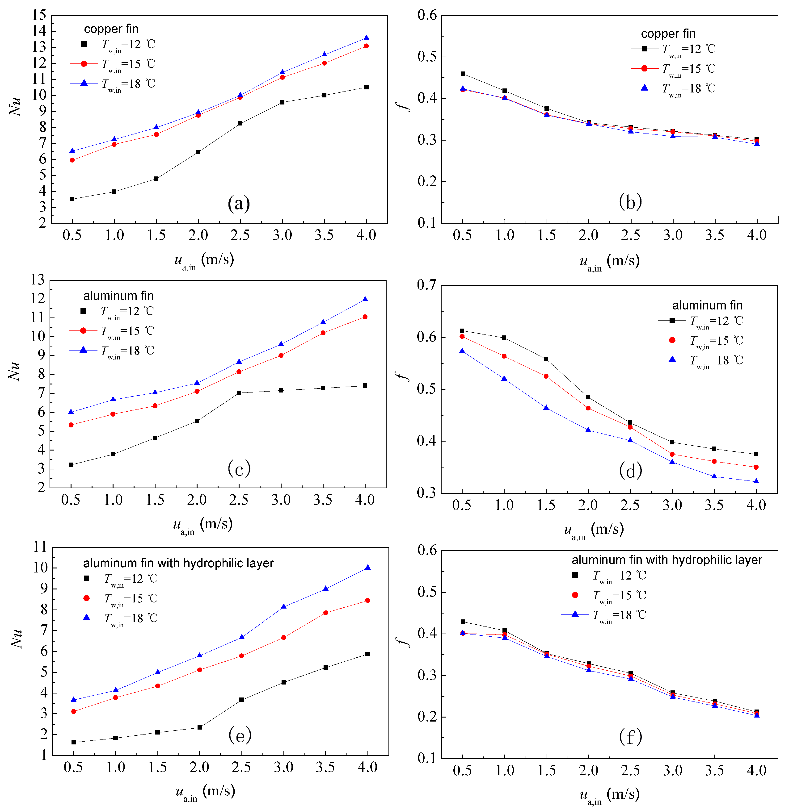
3.5. The Effect of ua,in on Nu and f of Heat Exchanger

Figure 11 shows the effect of ua,in on Nu and f of the three different fin materials at RHin = 50%, Ta,in = 27 °C, Tw,in = 12 °C. It can be found in Figure 11a that Nu of the three different fin materials all increase with the increase of ua,in. This is because the boundary layer becomes thinner with the increase of ua,in. The discharged speed of condensate water from the fin surface is accelerated, which further enhances the disturbance of the fluid, thus the heat transfer capacity is enhanced. Compared with 0.5 m/s, Nu of copper fin, aluminum fin, and aluminum fin with hydrophilic layer increase about 1.99, 1.30, and 2.62 times, respectively, at 4.0 m/s. Under the same air inlet velocity, Nu of the copper fins is larger than aluminum fins, and Nu of the aluminum fins is larger than that of aluminum fins with a hydrophilic layer.
As shown in Figure 11b, f decreases with increasing ua,in for all three fin materials. The reason is that with the increase of ua,in, the velocity of airflow increases, and the increase of kinetic energy of airflow is greater than that of pressure drop, and the condensate water can be discharged from the fin surface faster, which makes the air passage smoother and pressure drop decreases. Compared with 0.5 m/s, f of copper fin, aluminum fin, and aluminum fin with hydrophilic layer decrease about 34.46%, 38.81%, and 50.55%, respectively, at 4.0 m/s. At the same air inlet velocity, f of the aluminum fin is the largest, and f of the aluminum fin with hydrophilic layer is the smallest. This is because the condensation water produced on the fin surface will not gather on the fin surface after the hydrophilic layer is attached to the fin surfaces; the discharged speed of condensate water from the fin surface is accelerated, which will reduce the pressure loss of the air side channel.

3.6. The Effect of RHin on Nu and f of Heat Exchanger

The effect of RHin on Nu and f of three different fin materials at ua,in= 2 m/s, Ta,in = 27 °C, Tw,in = 12 °C is given in Figure 12. It can be seen from Figure 12a that the Nu of the three different fin materials all increases with the increase of RHin. It shows that increasing RHin can enhance the convective heat transfer intensity of the heat exchanger. This is because with the increase of RHin, the condensation rate on the low-temperature fin surface will accelerate, thus the proportion of latent heat transfer in the heat and mass transfer process will gradually increase. Moreover, with the increase of RHin, the discharge process is accelerated, which increases the disturbance of the air stream, thus the heat transfer performance of heat transfer is enhanced. Compared with RHin = 40%, Nu of the copper fin, aluminum fin, and aluminum fin with hydrophilic layer increased about 0.93, 1.23, and 3.12 times, respectively, at RHin = 80%. Under the same RHin, Nu of the copper fins is higher than that of aluminum fins, and Nu of the aluminum fins is higher than that of aluminum fins with a hydrophilic layer.
As shown in Figure 12b, f increases with the increase of RHin for all three fin materials. The main reason is that with the increase of RHin, the condensation and discharge process is accelerated, which enhances the disturbance of the air stream. Thus, the pressure drop of the air side increases. Compared with RHin = 40%, f of the copper fin, aluminum fin and aluminum fin with hydrophilic layer increases about 1.21, 1.38, and 1.03 respectively at RHin = 80%. At the same RHin, f of the aluminum fin is largest, and f of the aluminum fin with hydrophilic layer is smallest.

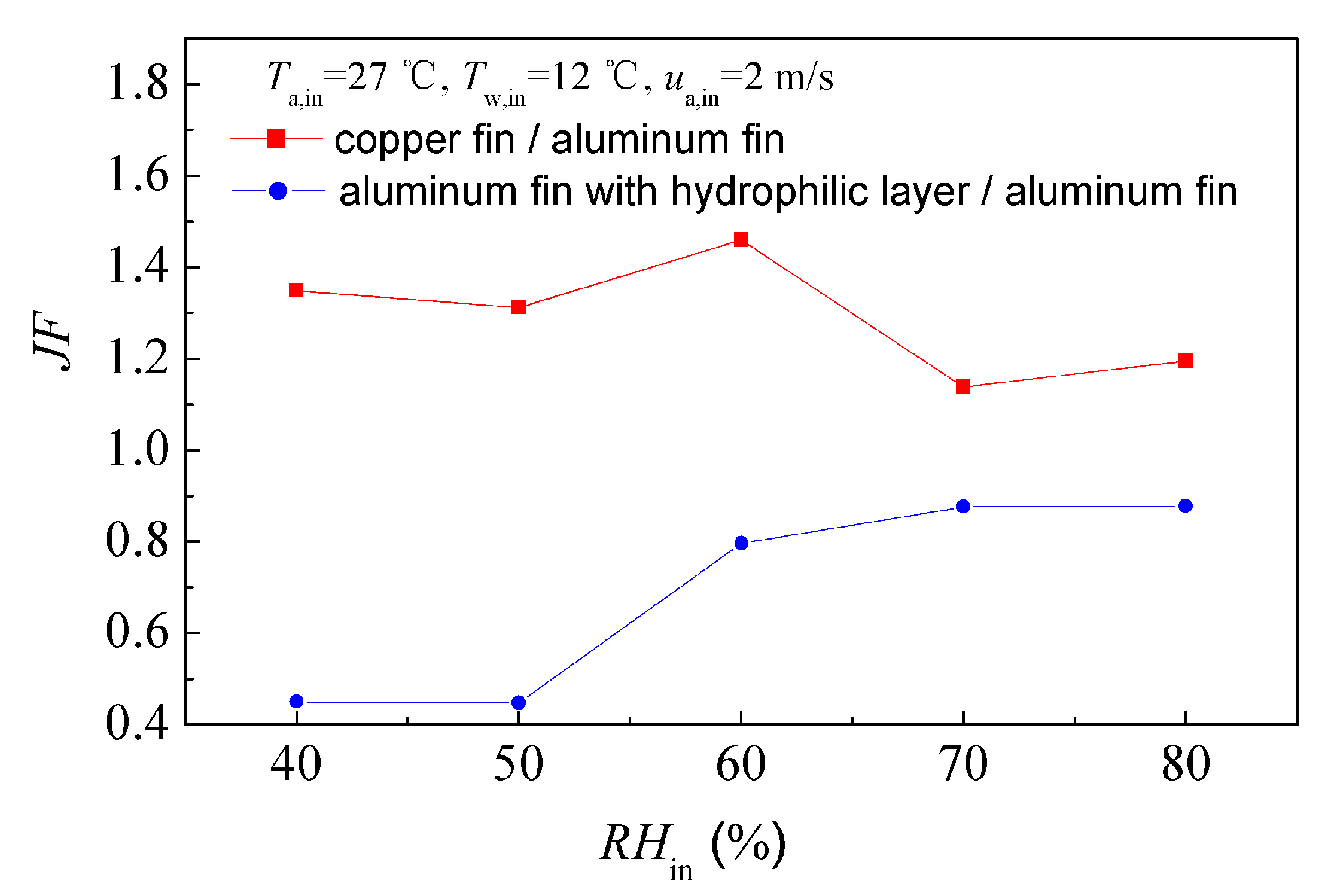
3.7. The Effect of the Fin Material on JF

In order to comprehensively evaluate the heat transfer and resistance characteristics of the three different fin materials cases under dehumidifying conditions, the thermal performance factor JF shown in Equation (9) is used as the evaluation criterion. As given in Equation (9), Nu and f of the aluminum fin are used as reference values.
Figure 13 shows the effect of ua,in on JF at RHin = 50%, Ta,in = 27 °C, Tw,in = 12 °C. As shown in Figure 13, the range of JFC,f/Al,f was 1.24–1.53 at ua,in = 0.5 m/s–4 m/s, they were all larger than 1.0. This shows that the comprehensive heat transfer performance of copper-fin-and-circular-tube heat exchanger is better than that of the aluminum fin heat exchanger. Moreover, with the increase of ua,in, the comprehensive heat transfer advantages of the copper fin heat exchanger are more obvious than that of the aluminum fin heat exchanger. However, the range of JFAl,f,h,l/Al,f was 0.48–0.96 at ua,in = 0.5 m/s–4 m/s, they were all smaller than 1.0. That is to say that the comprehensive heat transfer performance of the aluminum fin with hydrophilic layer heat exchanger was worse than that of the aluminum fin heat exchanger. With the increase of ua,in, the difference of comprehensive heat transfer capacity between aluminum fin with hydrophilic layer heat exchanger and aluminum fin heat exchanger becomes smaller.
The effect of RHin on JF at ua,in = 2 m/s, Ta,in = 27 °C, Tw,in = 12 °C is given in Figure 14. From Figure 14, we can see that the range of JFC,f/Al,f was 1.14–1.46 when RHin increased from 40% to 80%. JFC,f/Al,f were all larger than 1.0. Moreover, with the increase of RHin, JFC,f/Al,f gradually approached 1.0. The range of JFAl,f,h,l/Al,f was 0.45~0.88 at RHin = 40–80%. JFAl,f,h,l/Al,f was smaller than 1.0. Moreover, with the increase of RHin, JFAl,f,h,l/Al,f increased gradually and tended to be stable. This shows that with increasing of RHin, the differences in comprehensive heat transfer performance of the three heat exchangers with different fin materials become smaller and smaller.
For the three heat exchangers with different fin material, the above research show that the comprehensive heat transfer performance of the copper fin heat exchanger was the best, and the comprehensive heat transfer performance of aluminum fin with hydrophilic layer was the worst under dehumidifying conditions.

4. Conclusions

For a fin-and-circular-tube heat exchanger, we experimentally studied the effect of three different fin materials: copper fin, aluminum fin, and aluminum fin with hydrophilic layer on heat transfer and resistance performance, and the geometry form and movement characteristics of condensate water on the three fin surfaces were studied, too. JF was used to screen the optimum fin material at different ua,in and RHin. The main conclusions can be summarized as follows:
(1)
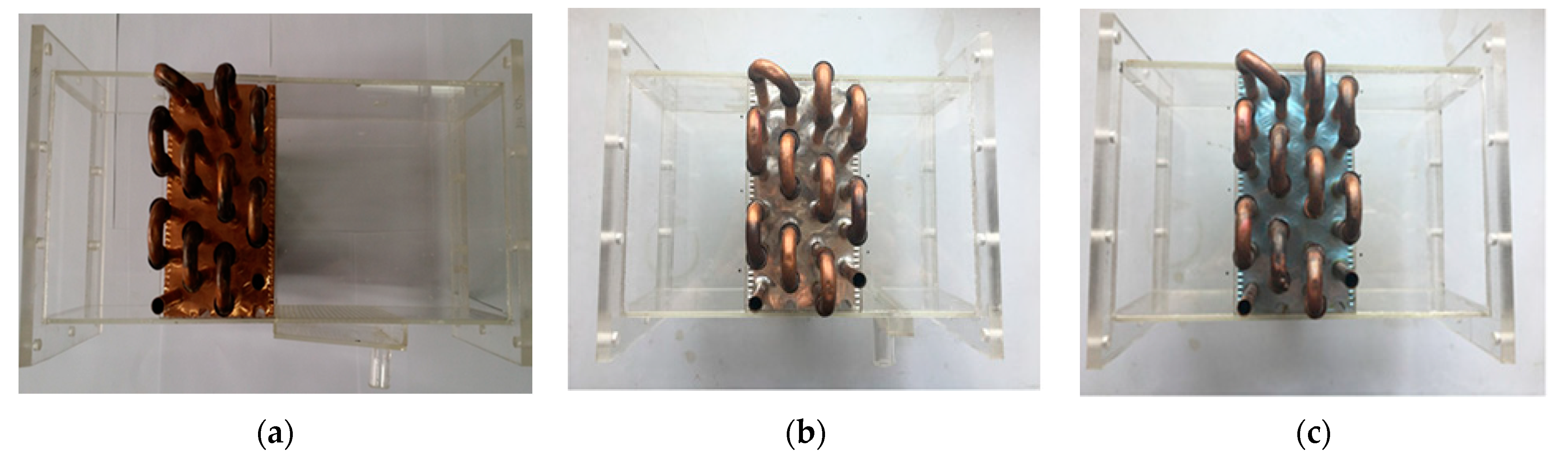
The condensation state on the surface of copper fin and aluminum fin is dropwise condensation. They all experience the process of nucleation, growth, coalescence, and discharge from the fin surface. The condensation state on the surface of the aluminum fin with the hydrophilic layer is film condensation.
(2)
Under the same air inlet velocity, Nu and f of Ta,in = 35 °C is largest, and then gradually decreases with the decrease of Ta,in. Nu decreases and f increases with the decrease of Tw,in.
(3)
At the same ua,in or RHin, for the three different material fins, the heat transfer performance of copper fin heat exchanger is the best, and heat transfer performance of aluminum fin with hydrophilic layer is the worst. f of the aluminum fin is the largest, and f of the aluminum fin with hydrophilic layer is the smallest.
(4)
Under identical pumping power conditions, the comprehensive heat transfer performance of the copper fin heat exchanger is the best for the studied three different fin materials.

Author Contributions

Conceptualization, W.-L.H. and Y.G.; methodology, W.-L.H.; software, Y.-B.Z.; validation, W.-L.H. and A.-J.M.; investigation, W.-L.H., Y.G. and J.W.; resources, W.-L.H.; writing—original draft preparation, W.-L.H. and A.-J.M.; writing—review and editing, W.-L.H., Z.-J.C., Y.G. and J.W.; visualization, W.-L.H. and Y.-B.Z.; supervision, Y.G.; project administration, W.-L.H.; funding acquisition, W.-L.H. and Y.G. All authors have read and agreed to the published version of the manuscript.

Funding

This research was funded by the National Natural Science Foundation of China, grant number 51868035; 51866006; 51468028, Foundation of A Hundred Youth Talents Training Program of Lanzhou Jiaotong University, and the Science and Technology Plan of Gansu Province, grant number 18JR3RA121.

Institutional Review Board Statement

Not applicable.

Informed Consent Statement

Not applicable.

Data Availability Statement

Not applicable.

Conflicts of Interest

The authors declare no conflict of interest.

Nomenclature

AArea (m2)
A0Total heat transfer area of air side surface (m2)
AtcOutside surface area of tubes (m2)
AafFin surface area (m2)
AminMinimum free flow area of heat exchanger (m2)
AfrFrontal area of heat exchanger (m2)
cpSpecific heat (J/kg·K)
cp,wSpecific heat of water (J/kg·K)
cp,aSpecific heat of air (J/kg·K)
daHumidity ratio of moist air (kg/kg)
dfbHumidity ratio of moist air at fin base (kg/kg)
deEquivalent diameter (m)
fFriction factor
GMass flow of air at the minimum free flow area (kg/m2·s)
hsAir side sensible heat transfer coefficient (W/m2· K)
iAir enthalpy (kJ/kg)
ifgSaturated water vapor enthalpy (kJ/kg)
ia,inInlet air enthalpy of heat exchanger (kJ/kg)
ia,outOutlet air enthalpy of heat exchanger (kJ/kg)
LxFin length along air flow direction (m)
mMass flow rate (kg/s)
maMass flow rate of air (kg/s)
mwMass flow rate of water (kg/s)
LeLewis number
NuNusselt number
JFThermal performance factor
pPressure (Pa)
QHeat transfer rate (W)
QaHeat transfer rate of air side (W)
QwHeat transfer rate of water side (W)
QaveAverage heat transfer rate (W)
RHRelative humidity of air (%)
TTemperature (°C)
TaAir temperature (°C)
TfbAverage temperature of fin base (°C)
Tw,outTemperature of outlet water (°C)
Tw,inTemperature of inlet water (°C)
uAir velocity (m/s)
ua,inInlet air velocity of heat exchanger (m/s)
ΔpPressure drop (Pa)
Greeks
λThermal conductivity (W/m·k)
ηf,wetWet fin efficiency
ηoSurface efficiency
ρDensity (kg/m3)
ρinDensity of inlet air of heat exchanger (kg/m3)
ρoutDensity of outlet air of heat exchanger (kg/m3)
ρmAverage density of air (kg/m3)
τTime (s)
σRatio of the minimum free flow area and the frontal area of heat exchanger
Subscripts
AAir
aveAverage value
fbFin base
frFrontal
inInlet parameters
mMean
outOutlet parameters
minMinimum value
wWater
C,fCopper fin
Al,fAluminum fin
Al,f,h,lAluminum fin with hydropholic layer

References

  1. He, Y.L.; Han, H.; Chu, P.; Tao, W.Q.; Zhang, Y.W.; Xie, T. Analysis of heat transfer and pressure drop for fin-and-tube heat exchangers with rectangular winglet-type vortex generators. Appl. Therm. Eng. 2013, 61, 770–783. [Google Scholar] [CrossRef]
  2. Hu, W.L.; Wang, L.B.; Guan, Y.; Hu, W.J. The effect of shape of winglet vortex generator on the thermal hydrodynamic performance of a circular tube bank fin heat exchanger. Heat Mass Transf. 2017, 53, 2961–2973. [Google Scholar] [CrossRef]
  3. Sadeghianjahromi, A.; Kheradmand, S.; Nemati, H.; Liaw, J.-S.; Wang, C.-C. Compound heat transfer enhancement of wavy fin-and-tube heat exchangers through boundary layer restarting and swirled flow. Energies 2018, 11, 1959. [Google Scholar] [CrossRef] [Green Version]
  4. Łęcki, M.; Andrzejewski, D.; Gutkowski, A.N.; Górecki, G. Study of the influence of the lack of contact in plate and fin and tube heat exchanger on heat transfer efficiency under periodic flow conditions. Energies 2021, 14, 3779. [Google Scholar] [CrossRef]
  5. Wang, C.-C.; Lin, Y.-T.; Lee, C.-J. An airside correlation for plain fin-and-tube heat exchangers in wet conditions. Int. J. Heat Mass Transf. 2000, 43, 1869–1872. [Google Scholar] [CrossRef]
  6. Wang, C.-C.; Hsieh, Y.-C.; Lin, Y.-T. Performance of plate finned tube heat exchangers under dehumidifying conditions. J. Heat Transf. 1997, 119, 109–117. [Google Scholar] [CrossRef]
  7. Wang, C.-C.; Chang, C.-T. Heat and mass transfer for plate fin-and-tube heat exchangers with and without hydrophilic coating. Int. J. Heat Mass Transf. 1998, 41, 3109–3120. [Google Scholar] [CrossRef]
  8. Jang, J.Y.; Lai, J.T.; Liu, L.C. The thermal-hydraulic characteristics of staggered circular finned-tube heat exchangers under dry and dehumidifying conditions. Int. J. Heat Mass Transf. 1998, 41, 3321–3337. [Google Scholar] [CrossRef]
  9. Ma, X.K.; Ding, G.L.; Zhang, Y.M.; Wang, K.J. Airside heat transfer and friction characteristics for enhanced fin-and-tube heat exchanger with hydrophilic coating under wet conditions. Int. J. Refrig. 2007, 30, 1153–1167. [Google Scholar] [CrossRef]
  10. Ma, X.K.; Ding, G.L.; Zhang, Y.M.; Wang, K.J. Effects of hydrophilic coating on air side heat transfer and friction characteristics of wavy fin and tube heat exchangers under dehumidifying conditions. Energy Convers. Manag. 2007, 48, 2525–2532. [Google Scholar] [CrossRef]
  11. Phan, T.-L.; Chang, K.S.; Kwon, Y.C.; Kwon, J.-T. Experimental study on heat and mass transfer characteristics of louvered fin-tube heat exchangers under wet condition. Int. Commun. Heat Mass Transf. 2011, 38, 893–899. [Google Scholar] [CrossRef]
  12. Kim, N.-H. An experimental investigation on the airside performance of fin-and-tube heat exchangers having radial slit fins under wet condition. J. Therm. Sci. Technol. 2016, 11, JTST0005. [Google Scholar] [CrossRef] [Green Version]
  13. Howongsakun, T.; Theerakulpisut, S.; Sujumnongtokul, P.; Palasan, P. The behavior of lewis number in finned tube cooling coils under highly moist inlet air conditions. Int. J. Technol. 2016, 7, 1253–1259. [Google Scholar] [CrossRef] [Green Version]
  14. Pirompugd, W.; Wongwises, S. Actual dry-bulb temperature and equivalent dry-bulb temperature methods for wavy fin-and-tube heat exchangers with dehumidification. Int. J. Heat Mass Transf. 2017, 106, 675–685. [Google Scholar] [CrossRef]
  15. Li, M.; Zhou, W.; Wei, J.; Tao, W.Q. 3D numerical simulation of heat and mass transfer of fin-and-tube heat exchanger under dehumidifying conditions. Int. J. Heat Mass Transf. 2018, 127, 597–610. [Google Scholar] [CrossRef]
  16. Zhang, G.H.; Wang, B.L.; Li, X.T.; Shi, W.X.; Cao, Y. Review of experimentation and modeling of heat and mass transfer performance of fin-and-tube heat exchangers with dehumidification. Appl. Therm. Eng. 2019, 146, 701–717. [Google Scholar] [CrossRef]
  17. Hazarika, S.A.; Bhanja, D.; Nath, S. A novel optimal constructal fork-shaped fin array design to ascertain thermo-heightened performance under dehumidifying conditions. Int. J. Therm. Sci. 2019, 144, 67–78. [Google Scholar] [CrossRef]
  18. Liu, X.; Chen, H.; Wang, X.; Kefayati, G. Study on surface condensate water removal and heat transfer performance of a minichannel heat exchanger. Energies 2020, 13, 1065. [Google Scholar] [CrossRef] [Green Version]
  19. Zhan, F.; Ding, G.; Zhuang, D. Numerical model of particle deposition on wet fin surfaces of heat exchanger under dehumidifying conditions. Int. J. Heat Mass Transf. 2020, 149, 119258. [Google Scholar] [CrossRef]
  20. Zhang, Y.; Zhang, G.; Qu, X.; Tian, M. Three-dimensional numerical simulation of gas-liquid falling film flow characteristics on the airside of finned-tube heat exchanger with a typical large fin pitch. Int. J. Heat Mass Transf. 2020, 162, 120347. [Google Scholar] [CrossRef]
  21. Nguyen, M.P.; Nguyen, V.H. Influence of inlet water temperature on heat transfer and pressure drop of dehumidifying air coil using analytical and experimental methods. Case Stud. Therm. Eng. 2020, 18, 100581. [Google Scholar] [CrossRef]
  22. Ayad, F.; Benelmir, R.; Idris, M. Thermal-hydraulic experimental study of louvered fin-and-flat-tube heat exchanger under wet conditions with variation of inlet humidity ratio. Appl. Therm. Eng. 2021, 183, 116218. [Google Scholar] [CrossRef]
  23. ASHRAE. ASHRAE Standard 41.2-1987: Standard Methods for Laboratory Air-Flow Measurement; American Society of Heating, Refrigerating and Air-Conditioning Engineers, Inc.: Atlanta, GA, USA, 1987; Available online: https://webstore.ansi.org/Standards/ASHRAE/ANSIASHRAE411987RA92?source=preview (accessed on 8 October 2021).
  24. Threlkeld, L. Thermal Environment Engineering; Prentice-Hall: New York, NY, USA, 1970. [Google Scholar]
  25. Liang, S.Y.; Wong, T.N.; Nathan, G.K. Comparison of one-dimensional and two-dimensional models for wet surface fin efficiency of a plate fin-tube heat exchanger. Appl. Therm. Eng. 2000, 20, 941–962. [Google Scholar] [CrossRef]
  26. Kays, W.M.; London, A.L. Compact Heat Exchanger, 3rd ed.; Mc Graw-Hill: New York, NY, USA, 1984. [Google Scholar]
Figure 1. Schematic diagram of the experimental system.
Energies 14 07030 g001
Figure 2. Test specimens: (a) copper fin, (b) aluminum fin, (c) aluminum fin with a hydrophilic layer.
Energies 14 07030 g002
Figure 3. Schematic diagram of CCD cameras arrangement.
Energies 14 07030 g003
Figure 4. Condensate droplets on the copper fin surface: (a) τ = 10 s, (b) τ = 60 s, (c) τ = 120 s, (d) τ = 160 s, (e) τ = 200 s, (f) τ = 230 s, (g) τ = 260 s, (h) τ = 290 s.
Energies 14 07030 g004
Figure 5. Condensate droplets on the aluminum fin surface: (a) τ = 10 s, (b) τ = 60 s, (c) τ = 120 s, (d) τ = 160 s, (e) τ = 200 s, (f) τ = 230 s, (g) τ = 260 s, (h) τ = 290 s.
Energies 14 07030 g005
Figure 6. Condensate water on the surface of the aluminum fin with a hydrophilic layer: (a) τ = 10 s, (b) τ = 60 s, (c) τ = 120 s, (d) τ = 160 s, (e) τ = 200 s, (f) τ = 230 s, (g) τ = 260 s, (h) τ = 290 s.
Energies 14 07030 g006
Figure 7. Effect of ua,in on geometry form of condensate water on the fin surfaces of three different materials: (a) copper fin, (b) aluminum fin, (c) aluminum fin with a hydrophilic layer.
Energies 14 07030 g007
Figure 8. Effect of RHin on geometry form of condensate water on the fin surfaces of three different materials: (a) copper fin, (b) aluminum fin, (c) aluminum fin with a hydrophilic layer.
Energies 14 07030 g008
Figure 9. Effect of Ta,in on Nu and f of three different fin materials: (a,c,e) Nu, (b,d,f) f.
Energies 14 07030 g009
Figure 10. Effect of Tw,in on Nu and f of three different fin materials: (a,c,e) Nu, (b,d,f) f.
Energies 14 07030 g010
Figure 11. Effect of ua,in on Nu and f: (a) Nu, (b) f.
Energies 14 07030 g011
Figure 12. Effect of RHin on Nu and f: (a) Nu, (b) f.
Energies 14 07030 g012
Figure 13. Effect of ua,in on JF.
Energies 14 07030 g013
Figure 14. Effect of RHin on JF.
Energies 14 07030 g014
Table 1. Structural parameters of the three test specimens.
Transverse Tube PitchLongitudinal Tube PitchOutside Diameter of TubeFin
Thickness
Net Fin SpacingFin Length along Air Flow DirectionNumber of Tube Row
25.3 mm22.0 mm10.0 mm0.12 mm2.0 mm88 mm4
Publisher’s Note: MDPI stays neutral with regard to jurisdictional claims in published maps and institutional affiliations.

