Article

Three-Dimensional Thermal Simulations of 18650 Lithium-Ion Batteries Cooled by Different Schemes under High Rate Discharging and External Shorting Conditions †

1
Key Laboratory of Ocean Energy Utilization and Energy Conservation of Ministry of Education, Dalian University of Technology, Dalian 116024, China
2
State Key Laboratory of Multiphase Flow in Power Engineering, Xi’an Jiaotong University, Xi’an 710049, China
3
Department of Mechanical and Mechatronics Engineering, University of Waterloo, 200 University Avenue West, Waterloo, ON N2L 3G1, Canada
*
Authors to whom correspondence should be addressed.
Part of this work has been published as conference paper at 27th CAHE Engineering Thermophysics Annual Conference, Xiangtan, China, 21–22 May 2021, as paper B-2021079.
Energies 2021, 14(21), 6986; https://doi.org/10.3390/en14216986
Submission received: 6 October 2021 / Revised: 19 October 2021 / Accepted: 20 October 2021 / Published: 25 October 2021

Abstract

:
In this work, three-dimensional thermal simulations of single 18650 lithium-ion battery cell and 75 V lithium-ion battery pack composed of 21 18650 battery cells are performed based on a multi-scale multi-domain (MSMD) battery modeling approach. Different cooling approaches’ effects on 18650 lithium-ion battery and battery pack thermal management under fast discharging and external shorting conditions are investigated and compared. It is found that for the natural convection, forced air cooling, and/or mini-channel liquid cooling approaches, the temperature of battery cell easily exceeds 40 °C under 3C rate discharging condition. While under external shorting condition, the temperature of cell rises sharply and reaches the 80 °C in a short period of time, which can trigger thermal runaway and may even lead to catastrophic battery fire. On the other hand, when the cooling method is single-phase direct cooling with FC-72 as coolant or two-phase immersed cooling by HFE-7000, the cell temperature is effectively limited to a tolerable level under both high C rate discharging and external shorting conditions. In addition, two-phase immersed cooling scheme is found to lead to better temperature uniformity according to the 75 V battery pack simulations.

1. Introduction

Lithium-ion batteries are regarded as one of the most promising power sources in the worldwide trend of vehicle electrification. The wide application of lithium-ion batteries in electric vehicles (EV) and hybrid electric vehicles (HEVs) draws urgent need for developing propriate lithium-ion batteries thermal management systems [1,2], as the performance, durability, as well as safety of lithium-ion batteries are highly dependent on cell temperature [3]. While, cooling is an important aspect of the lithium-ion battery thermal management due to two major reasons. First, under normal operating conditions, the lithium-ion battery generates heat. The heat needs to be dissipated to keep the battery temperature lower than a certain level (about 40 °C) to prevent capacity loss of the lithium-ion battery cell [4]. Meanwhile, temperature uniformity is wanted inside every single battery cell and between battery cells in battery pack. As the non-uniformity of temperature in cells may lead to non-uniformity of cell aging, even may cause inconsistency of cell state-of-charge (SOC) [5]. Second, if cell temperature reaches 80–100 °C, there is risk that the thermal runaway process will be triggered and catastrophic battery fire may even happen [4]. The thermal runaway can be caused due to various reasons [6], while internal shorting [7] and external shorting [8] are possible triggers for the thermal runaway. Ceasing the thermal runaway under internal shorting condition via cooling approach is hard [9]. However, under external shorting condition, there is a possibility that the temperature of lithium-ion battery cell can be limited. The difference of the internal shorting and the external shorting from the heat transfer aspect is that the heat generated from internal shorting is confined at a small volume. The internal shorting causes the local temperature to rise at a very short time period, while most of the cell area may still remain cool at such short time period. The temperature rise during the small period of time is basically governed by heat generation, cell heat capacity, and heat conduction inside the battery cell. The cooling method, which can provide heat transfer coefficient at the battery surface, has little effectiveness for such a process. On the other hand, under certain external shorting conditions, for example the cell is shorted by a resistance not so large as discussed in this study, the cell temperature will have a relatively uniform temperature rise. As most of the cell surface experiences temperature rises, the cooling method can remove a lot of heat. When the heat transfer coefficient is high enough, then, the cell temperature will not reach 80 °C. Thus, the goal of lithium-ion battery cooling is maintaining lithium-ion battery temperature to be lower than a certain level (about 40 °C) and to get uniform temperature distributions both inside a single cell and inside a battery pack under battery operating condition, even under very aggressive operating conditions like very fast discharging condition. The goal of lithium-ion battery cooling also contains suppressing the temperature or delaying the fast temperature rise of a battery under extreme conditions, like external shorting, to prevent the thermal runaway.
The most common lithium battery cooling approaches include air cooling [10,11] and mini-channel plate liquid cooling [12,13]. Other cooling approaches include phase change materials (PCM) cooling [14], heat pipe cooling [15], direct liquid cooling (single-phase) [16], and direct liquid cooling (two-phase) [17]. The direct liquid cooling means that the dielectric cooling fluid directly contacts the surface of the lithium-ion batteries to cool the cell. The advantage of direct liquid cooling is that the thermal resistance can be shortened compared with indirect cooling. Immersed cooling is a possible method for direct liquid cooling of lithium-ion batteries with pool boiling heat transfer as its mechanism. The dielectric fluid immersed cooling has been developed as an effective method for electronics cooling [18,19], and adoption of immersed cooling for chips or devices is growing fast in electronic industries. Thus, whether the emerging immersed cooling method is suitable with lithium-ion batteries cooling is worth investigating. Van Gils et al. [20] proposed to immerse lithium-ion battery cell into 3M HFE-7000, which is dielectric cooling fluid with a boiling point of around 34 °C, to cool the battery. It was found that the pool boiling process improves the temperature uniformity of the battery and the pressure in the boiling chamber affects the intensity of the boiling process. Du et al. [21] developed a cooling method with hybrid heat pipe and immersed cooling method. Through immersing a full battery pack into 3M Novec 649, the thermal runaway propagation between cells was successfully suppressed. Although there were tests for exploring immersed cooling of lithium-ion battery, the immersed cooling of batteries still needs more study regarding more operating relevant conditions compared to other cooling methods.
Modeling is a powerful approach for lithium-ion battery cooling design [22]. Karimi and Li [23] developed a two-dimensional model to study the temperature distributions in a lithium-ion battery pack. The heat generation from the entropy change and electrochemical reactions is calculated from a mathematical equation, while the critical parameters of resistance in the equation were well taken from experimental measurement. Then, by supplying a uniform heat generation term into the battery cell domain, the model was established. Temperature distributions under natural convection cooling and forced air cooling were carefully discussed. Kalkan et al. [24] performed numerical simulations of a LiFePO4 pouch type lithium-ion battery with multi-scale multi-domain (MSMD) modeling approach [25]. At the electrochemical reaction scale, the so called NTGK model [26] was used for calculating the volumetric current transfer density and heat source terms. Then, at the regular scale, the transport equations of phase potentials and temperature were solved. The natural convection was directly simulated by assigning air domain near the cell wall and conducting the conjugate heat transfer modeling. For the forced air cooling, Xie et al. [27] performed structural optimization of lithium-ion battery pack by modeling different modeling configurations. Three factors of the air inlet angle, the air outlet angle, and the widths of air flow channel were considered in their work. Yang et al. [28] assessed the forced air cooling performance of a cylindrical battery pack with a modeling method coupling a 2D conjugate heat transfer model coupled with a 1D electrochemical model. Specific comparisons between aligned and staggered battery cell arrangements were made. Other recent works on optimizing the forced air cooling for lithium-ion battery packs include studies from Saw et al. [29], Wang et al. [30], Zhou et al. [31], and Li et al. [32].
There were also simulation studies to investigate methods of mini-channel cold plate cooling or direct liquid single-phase cooling on the lithium-ion batteries thermal management. Huo et al. [33] conducted three-dimensional thermal simulations for mini-channel cold plate cooling of lithium-ion batteries by assigning a heat source to cell domain and solving the conjugate heat transfer problem. The effects of channel number, flow direction, and inlet mass flow rate under 5C discharging condition were discussed. In a following study, Wu et al. [34] simulated a battery pack cooled by baffled cold plate. The influence of baffled cold plate geometrical parameters on the heat transfer enhancement was discussed. Panchal et al. [35] modeled a large format lithium-ion battery cooled by liquid cold plate with similar method under different cell operating temperatures. Li et al. [36] simulated a 50 V lithium-ion battery pack composed of 14 20 Ah battery cells under fast discharging condition with MSMD modeling method. In a recent study, Cao et al. [37] established thermal modeling of full-size-scale cylindrical battery pack cooled by wavy mini-channel cold plate. Their work demonstrated the battery thermal modeling approach’s capability can be pushed forward to industrial scale battery pack simulations. As for the direct liquid single-phase cooling for lithium-ion batteries, not many previous simulation works have been undertaken on it. Tan et al. [38] performed three-dimensional thermal simulations to investigate the direct liquid cooling of a fast-charging lithium-ion battery pack with HFE-6120 as coolant. Effects of the flow velocity, the channel height, the multilayer structure, and the cross-flowing configuration were elucidated. Patil et al. [39] modeled a 50 V lithium-ion battery pack cooled by direct single-phase liquid cooling. An MSMD approach with NTGK submodel was used in their research, and it was found that the dielectric fluid direct cooling facilitated in maintaining the pack temperature under 40 °C under 3C discharge condition with a moderate pumping power, which means the direct cooling is a promising cooling method for lithium-ion batteries.
The motivation of this study comes in two major ways. First, although there are many modeling studies on lithium-ion battery cooing designs, a systematic comparison of different cooling methods under extreme working conditions, say fast discharging and external shorting condition, is lacking. Thus, with a MSMD modeling framework [25] with equivalent circuit model (ECM) [40] as a submodel, this study directly compared the cooling methods of natural convection cooling, forced air cooling, mini-channel cold plate cooling, single-phase direct cooling, and immersed pool boiling cooling with single battery thermal simulations. Second, the simulations of immersed pool boiling cooling of lithium-ion batteries remains unexplored. In this study, a simplified approach is used to estimate the thermal responses of batteries under immersed cooling. The simulations aim to point out the potential advantage of immersed cooling in lithium-ion battery temperature regulation. It is found that the immersed cooling has the potential advantage of suppressing highest temperature, reducing the cell temperature variations under dynamic load, and improving the temperature uniformity in single cell and in battery pack under extreme battery operating conditions. More delicate model development for describing immersed pool boiling heat transfer will be done in the future.

2. Modeling Method

2.1. Modeling Domain and Multi-Scale Modeling Schematic

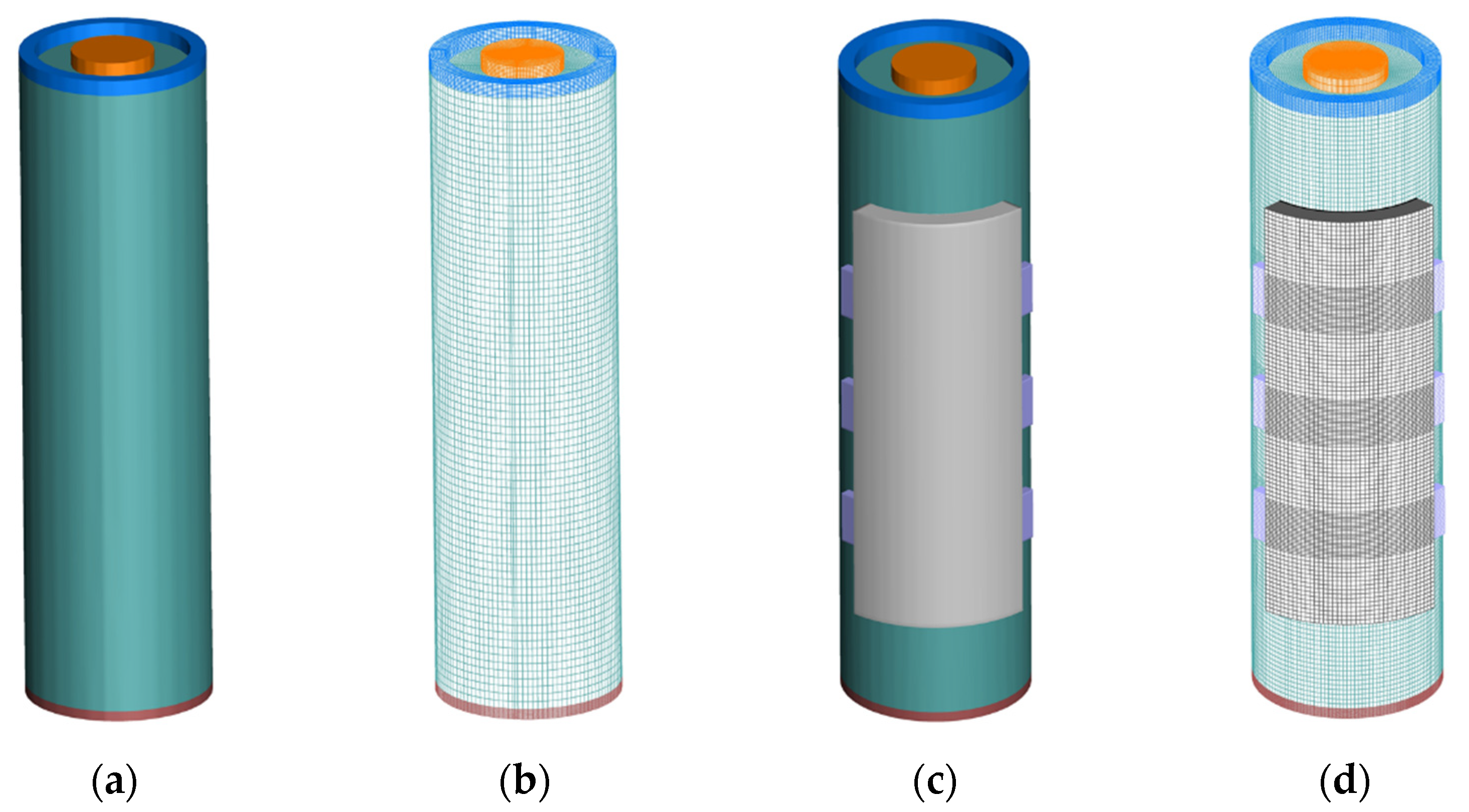
The cylindrical lithium-ion battery named INR18650-25R manufactured by Samsung (Seoul, South Korea). was used in this study. The nominal voltage and nominal capacity of this high energy lithium-ion battery are 3.6 V and 2.5 Ah. In this study, the thermal management of the INR18650-25R battery is specifically investigated, and the cooling performance of the cell under five cooling schemes, including natural convection, forced air cooling, mini-channel liquid cooling, single-phase direct cooling by FC-72, and two-phase immersed cooling by HFE-7000 are studied. The geometric models and mesh for natural convection and two-phase immersed cooling by HFE-7000 are shown in Figure 1a,b. Additionally, the geometric models and mesh for mini-channel liquid cooling are shown in Figure 1c,d. The geometric models and mesh for forced air cooling and single-phase direct cooling by FC-72 are shown in Figure 2. While, the cell characteristics and the specific parameters of the mini-channel plate are listed in Table 1.
For modeling the single battery cell, three domains are considered inside battery cells in the modeling, which are cell domain, negative tab domain, and positive tab domain. The model of two-phase immersed cooling by HFE-7000 is essentially the same as that of natural convection, except that the convective heat transfer coefficient in the case of natural convection is replaced by the pool boiling convective heat transfer coefficient obtained by van Gils et al. [20]. The forced air cooling modeling geometry is basically the same as that of single-phase direct cooling by FC-72, which contains four domains: cell domain, negative tab domain, positive tab domain, and the coolant domain. The coolant enters the coolant domain through the inlet and cools the cylindrical cell by direct contact, then flows out from the outlet. In order to show the model more explicitly, partial transparency is set for the coolant domain in Figure 2. Five domains are considered in the model for mini-channel liquid cooling, which are cell domain, negative tab domain, positive tab domain, cold plate domain, and the coolant domain. The coolant enters the cold plate through the inlet and absorbs the heat generated by the lithium-ion battery during its operation by indirect contact.
After completing the modeling of the single cell cooling, a battery pack of 21 such cylinder cells connected in series with a nominal voltage of 75 V is modeled. The battery packs cooled by FC-72 single-phase forced cooling and HFE-7000 two-phase pool boiling cooling are studied. The cylindrical cell is composed of a variety of materials. Therefore, lithium-ion battery can be regarded as a composite material. Table 2 lists the electrical and thermal parameters assumed in this study. In this paper, the purpose of modeling a lithium-ion battery is to explore the advantages of immersed cooling by HFE-7000 over conventional cooling methods, and at the same time, to provide practical assistance for future thermal design of battery packs using fluorinated liquid immersion cooling.
Lithium-ion battery modeling is difficult accounting to its multi-scale feature. In order to predict the temperature, taking into account the thermal management method, the transport equations of cell scale need to be solved. On the other hand, for capturing the detailed electric and thermal heat source terms, a detailed electrochemical submodel is needed at each computational node inside the battery cell. Thus, usage of multi-scale multi-domain modeling is needed for conducting 3D thermal modeling of lithium-ion battery and lithium-ion battery pack. On the cell scale, the equation governing the current flux is expressed as:
· ( σ + φ + ) = j
· ( σ φ ) = j
where φ + and φ are the positive and negative potentials, while σ + and σ are the effective electrical conductivity. The equations of different scales are bridged by the volume current density j, which can be calculated in the sub-scale electrochemical sub-model. The cell-scale and sub-scale models interact with each other and forecast the electric flux, meanwhile, the source term of the heat transfer equation is generated, and the temperature equation is then solved.
The ECM and Newman models both can be used as subdomain electrochemical models. The Newman model based on the internal reaction principle of cell has high accuracy. However, for Fluent advanced addon module, several important parameters are not available for users’ modification. Therefore, it is hard to accurately simulate the above lithium-ion battery with the Newman model. On the other hand, the ECM model used in this paper is an effective method for modeling lithium-ion batteries. The model uses a voltage source to represent the thermodynamic equilibrium potential of cells and, simultaneously, uses a resistance capacitance (RC) network to describe the kinetic characteristics of the battery. The parameters adjustment for ECM is relatively simple and the numerical solving speed is highly efficient, therefore, the model is useful for various operating conditions of power cell simulations. It is worthwhile to mention that numerical modeling is the major approach used in this study. For the single-phase cooling, the numerical solutions of the heat conduction or conjugate heat transfer problem can basically reflect the physics well with high fidelity. Additionally, for the two-phase cooling, more future experimental work is needed to confirm that the immersion cooling could bring significant advantages for lithium-ion battery thermal management.

2.2. Equivalent Circuit Model and Conjugate Heat Transfer Modeling

The equivalent circuit model uses a circuit network of conventional circuit elements such as resistors, capacitors, and constant voltage sources to describe the external responses of the power cell, and then solves for the evolution of the voltage from the circuit equation.
V ( t ) = V O C V V t r a n , s V t r a n , L R s e r i e s I ( t )
d V t r a n , s d t = 1 R t r a n , s C t r a n , s V t r a n , s 1 C t r a n , s I ( t )
d V t r a n , l d t = 1 R t r a n , l C t r a n , l V t r a n , l 1 C t r a n , l I ( t )
d ( S O C ) d t = I ( t ) 3600 Q r e f
In these equations, V O C V , V t r a n , s , V t r a n , l , and R s e r i e s 
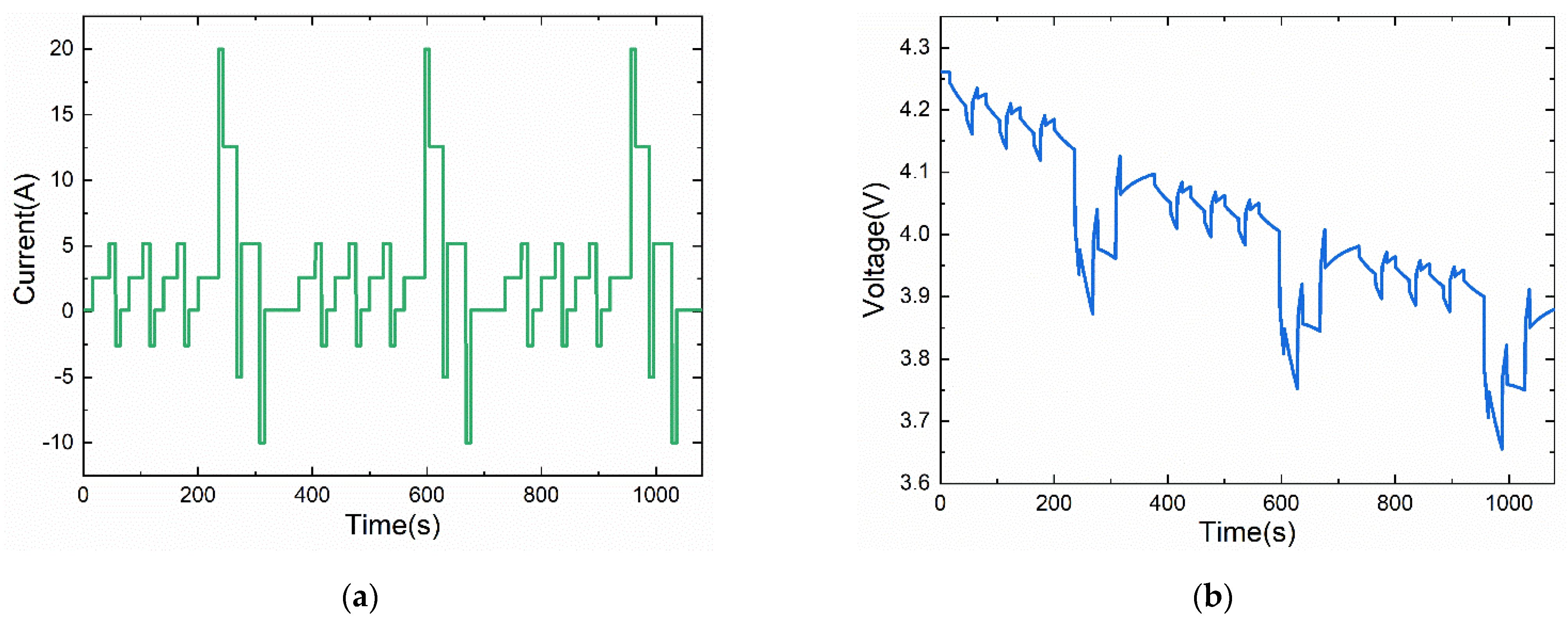
are the functions of SOC. The experimental data of I-V performance of INR18650-25R battery with different discharging rates were fitted by parameters adjustment, and the fitted parameters are listed in the following equation:
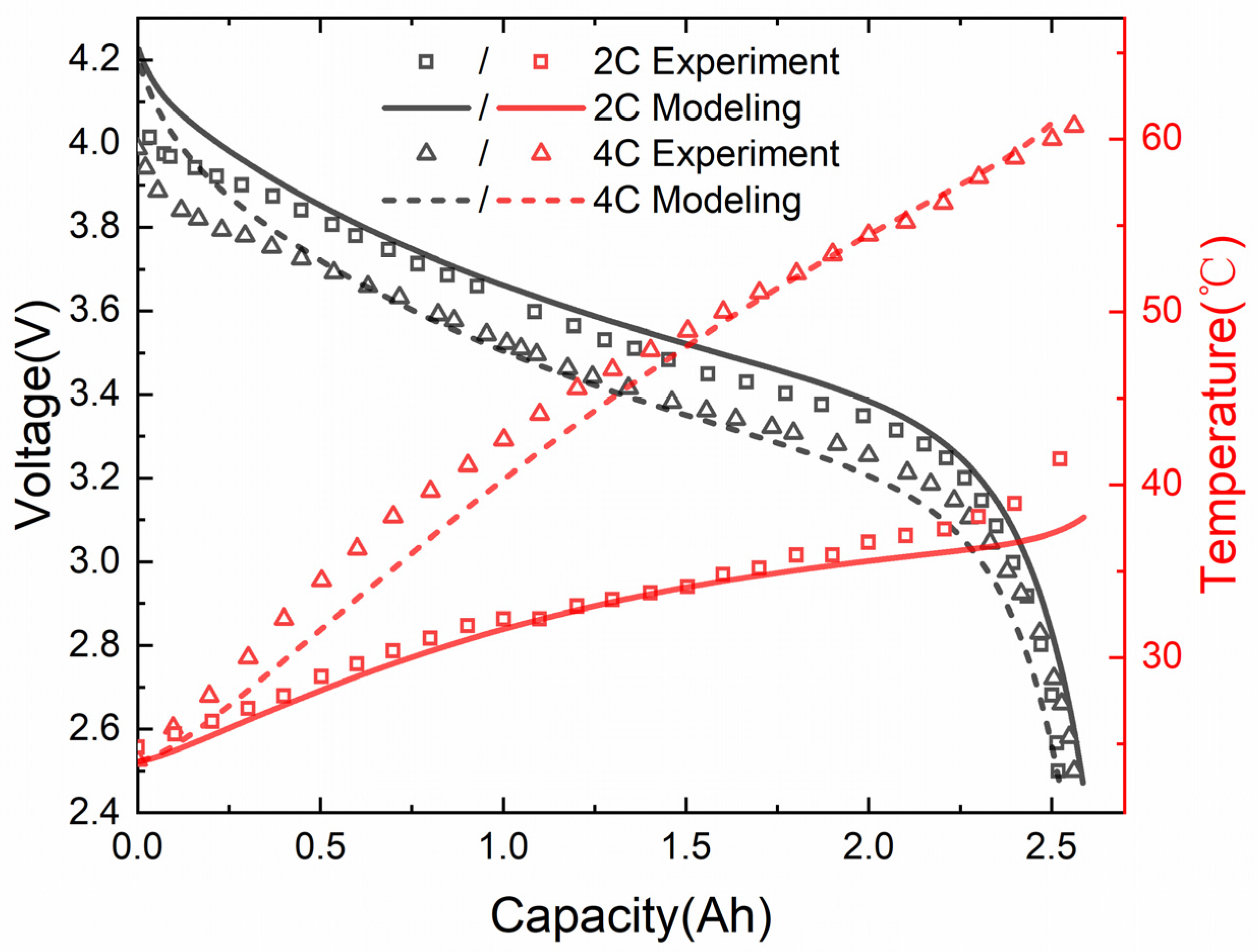
V O C V = 3.5 + 0.48 S O C 0.1178 S O C 2 + 0.4 S O C 3 1.031 e x p ( 13.5 S O C )
R s e r i e s = 0.02 + 0.1562 e x p ( 24.37 S O C )
R t r a n , s = 0.04669 + 0.3208 e x p ( 29.14 S O C )
C t r a n , s = 703.6 752.9 e x p ( 13.51 S O C )
R t r a n , l = 0.04984 + 6.603 e x p ( 155.2 S O C )
C t r a n , l = 4475 6056 e x p ( 27.12 S O C )
As shown in Figure 3, with these parameters, the voltage and temperature curves calculated by the model are in good match with the experimental measurements. After solving the ECM equation, the volumetric transfer current density can be calculated from:
j = I Q t o t a l Q r e f V C V
The electrochemical volumetric heat source term can be divided into a reversible heat source term and an irreversible heat source term, where the irreversible heat source term is: j [ V O C V ( φ + φ ) ] and the reversible source term is: j T d U d T . In addition, it also includes ohmic heating. Therefore, the heat source term can be expressed as q ˙ = j [ V O C V ( φ + φ ) T d U d T ] + σ + φ + · φ + + σ φ · φ .
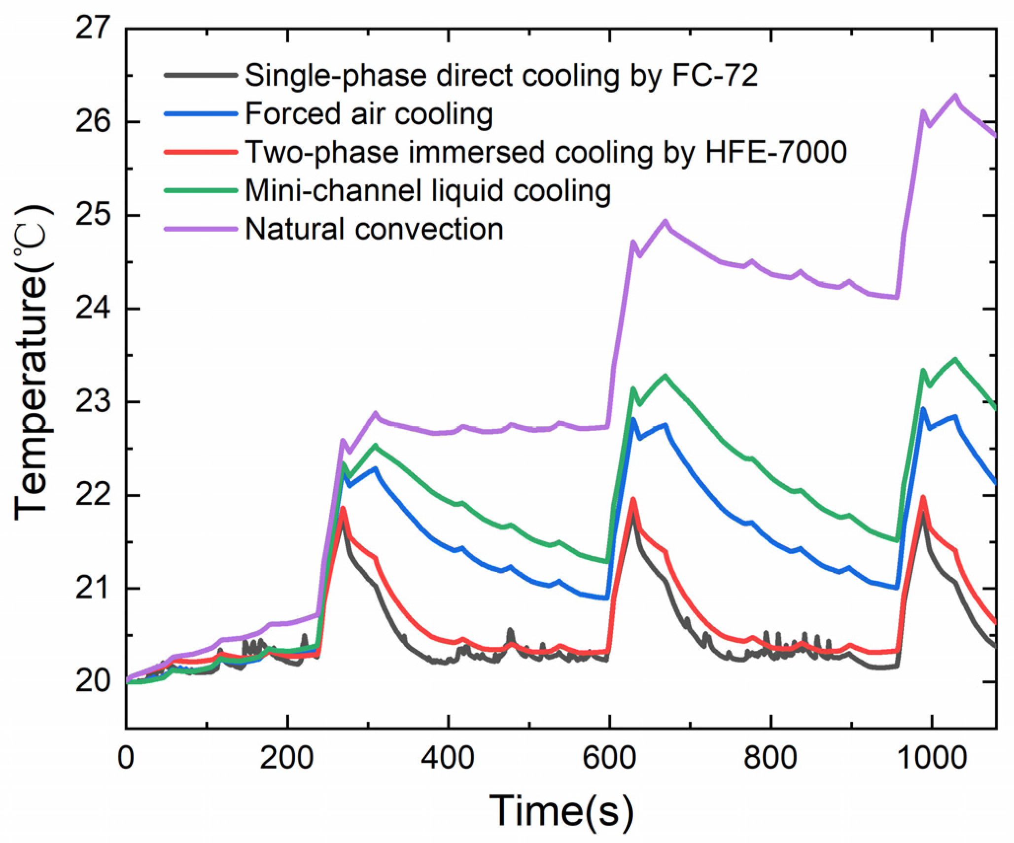
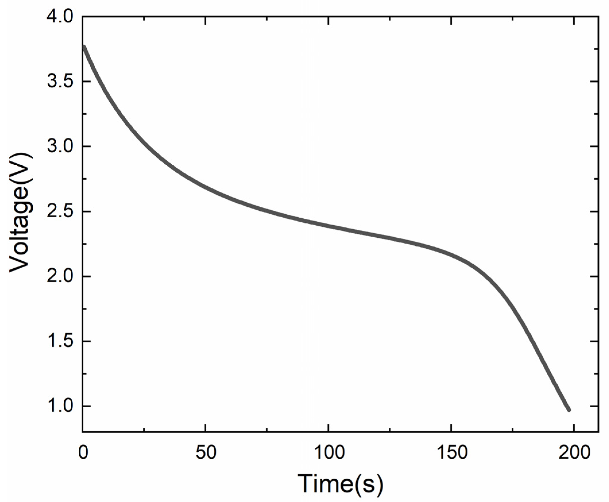
This paper used SolidWorks for 3D modeling and ANSYS FLUENT for 3D thermal simulation. The initial temperature of cell was set to 20 °C for all the above five cooling conditions. For the forced air cooling model, the air temperature was set to 20 °C and the inlet speed was set to 5 m/s. For the model of single-phase direct cooling by FC-72 and the model of mini-channel liquid cooling, the initial temperature of the cooling medium was set to be 20 °C and the inlet velocity of both cooling media was set to be 0.1 m/s. In the calculation of high C rate discharging, the time step used was 2 s and the maximum iteration step was 20. The convective heat transfer coefficient of two-phase immersed cooling by HFE-7000 was assigned with user defined boundary condition function of ANSYS (ANSYS Inc., Pittsburgh, PA, USA) Fluent. Different scenarios of high discharge rate, external short circuit, dynamic loading, and large battery packs were simulated in this study. The different cooling methods generally mean different heat transfer capability, or the heat transfer coefficient on the lithium-ion battery surface. Thus, running one scenario could already provide a lot of helpful information about the comparison for different cooling methods. However, besides the direct comparison of heat transfer coefficient, the studies with other scenarios also have meanings. For example, under the external short-circuit condition, if the cell is shorted by a certain external resistance, whether the cell temperature would reach 80 °C under different cooling methods is unknown. Another circumstance is that the temperature non-uniformity may not be large under low discharge rate, but under high discharge rate, the temperature non-uniformity could be a major problem. Those features may not be identical under different conditions. For the dynamic loading scenario, the good cooling method can suppress the temperature and suppress the temporal variations of the lithium-ion battery cell in the meantime. Thus, with simulations under dynamic loading scenarios, how small the temperature temporal variation is with different cooling method can be quantified. Additionally, the results are meaningful to determine whether a very fast active control system for battery temperature is needed or not. For the battery pack modeling, the temperature non-uniformity in the flow direction between cells can be investigated compared with single battery cell modeling.

3. Results and Discussion

3.1. Single Cell under High C Rate Discharging Condition

The temperature responses of individual lithium-ion cells under 3C and 5C discharging conditions were first explored. Studies indicate that the temperature of a lithium battery will gradually increase during the discharge process, and the rate of temperature rising is relatively stable most of the time, however, the temperature rises dramatically near the end of discharging. This phenomenon is attributed to the fact that the ohmic heat source is constant under constant C rate discharging condition. Accounting for the electrochemical characteristics of lithium-ion batteries, a relatively stable region exists during the discharge, as shown in Figure 3, in which the voltage curve is almost linear. The temperature from Figure 3 is taken from the center of the cell surface to make it comparable with experimental data. As the irreversible heat generated by the electrochemical reaction rises gradually, the temperature of the cell also rises continuously. For lithium-ion batteries, the negative and positive electrode both have equilibrium overpotential corresponding to different lithiation states. For the negative electrode, which is composed of graphite, the state of charge near zero will cause a sharp rise of equilibrium overpotential. For the positive electrode, which is composed of NCM, for example, it will cause a sharp drop of equilibrium overpotential near full lithiation. Additionally, the voltage of positive electrode minus voltage of negative electrode is basically the cell voltage. The fast discharging condition brings additional kinetics loss, but the basic shape of the voltage during discharging is mostly determined by the equilibrium voltage at different states of charge. It explains why the voltage sharply drops at the end of discharge. Then, the reversible heat, which is a large heat source term, basically follows the trend of OCV minus cell voltage. Thus, the lithium-ion battery cell will experience faster temperature rise near the end of discharge.
The maximum temperatures from the lithium-ion battery cell domain were distracted from modeling, and those maximum temperature curves under five cooling methods at 3C rate are compared in Figure 4. It is found that when the battery is under natural convection without sufficient cooling capability, its temperature will exceed 45 °C. The operation of a lithium-ion battery under such conditions will accelerate the generation of SEI film, which hinders the long-term performance of the battery. On the other hand, when the battery discharges at 3C rate under the other four cooling schemes, such as forced air cooling, mini-channel liquid cooling, single-phase direct cooling by FC-72, or two-phase immersed cooling by HFE-7000, the maximum temperature of cell is always below 35 °C, i.e., the battery temperature is always within the optimal operating temperature, which is helpful for extending the lifetime of the lithium-ion battery. The pumping power used for the single battery forced air cooling, mini-channel cold plate cooling, and single-phase direct cooling by FC-72 cases are 0.79 W, 4.87 × 10⁻⁵ W, and 8.86 × 10⁻³ W by estimating the pressure drop and volumetric flow rate. For the schemes of natural convection and two-phase immersed cooling, as the liquid domain has not been drawn in the study, it is hard to estimate the pumping power. The pumping power for cooling the battery surface is zero, but essentially it needs pumping power to take the dissipated heat away from the system. The pumping power for constructing the immersion two-phase lithium-ion battery cooling whole system still needs future study.
The maximum temperature curves under five cooling conditions at 5C discharge are shown in Figure 5, it can be seen that when the battery is cooled by natural convection, the temperature of the lithium-ion battery rises rapidly, and at the end of discharge, the temperature of the cell rises to 69 °C, which is a quite high temperature for normal lithium-ion battery operation. Compared with natural convection, when the battery adopts traditional cooling schemes such as forced air cooling and mini-channel liquid cooling, although the temperature rise rate of cell can be effectively slowed down, the maximum temperature still exceeds 40 °C at the end of 5C rate discharging. The mini-channel cold plate cooling leads to unexpected high temperature non-uniformity in this study. The reasoning is that the plate wall does not cover the entire cell wall of the cylindrical battery cell. Although the 18650 cell is small, the large temperature non-uniformity is still seen under fast discharging conditions for the mini-channel liquid cooling scheme. The natural convection basically cannot withstand those harsh conditions. However, with the forced air cooling, as the air passes and contacts most of the cell surface, more uniform temperature distribution is resulted. Thus, when designing mini-channel cold plates for cylindrical cells, the temperature non-uniformity is a problem to be aware of due to the partial contact of the cold plate to the cell wall. The single-phase direct cooling by FC-72 and two-phase immersed cooling show significant advantages of lowering the highest temperature and temperature non-uniformity under 5C discharging condition as shown in Figure 6a,c. For battery cooling, lowering the highest temperature and controlling temperature non-uniformity are both highly important, rather than keeping the average cell temperature low. The non-uniform temperature distribution can cause the jellyroll to deform in the long-term and eventually lead to safety hazards. However, when the battery uses single-phase direct cooling by FC-72 or two-phase immersed cooling by HFE-7000, the maximum temperature of cell during the entire discharge process does not exceed 30 °C. This suppressed temperature rise provides a benefit to prolong the lifetime of the lithium-ion battery.
The maximum temperature clouds under five cooling conditions at 5C discharge are shown in Figure 6. It is found that the temperature distribution of the cylindrical lithium-ion battery is not uniform, on account of the fact that cylindrical lithium-ion batteries are made of multiple material coils thus contributing to the poor thermal conductivity of the battery in the radial direction and allowing more heat to accumulate at the core location of the cell. However, compared to forced air cooling, mini-channel liquid cooling and single-phase direct cooling by FC-72, the surface temperature of the cell is more uniform when the cell adopts two-phase immersed cooling by HFE-7000. 5C discharge is an extreme condition for batteries, it basically brings the maximum heat flux that needs to be dissipated by battery cooling method under the scope of battery operation. It is found that direct cooling by single-phase or pool boiling heat transfer show stronger heat removal capability than the heat that needs to be dissipated for today’s lithium-ion batteries operation.

3.2. Single Cell under Dynamic Load Conditions

At present, static test methods are frequently used to evaluate the performance of batteries, i.e., constant current conditions are used for charge and discharge tests, however, there are instantaneous high current surges and instantaneous switching between charge and discharge in practical operation. Therefore, it is necessary to explore the temperature response of cell under dynamic loading conditions. At present, the dynamic stress test condition proposed by the United States Advanced Battery Consortium (USABC) is widely adopted in international standards for the performance evaluation of power batteries. This method evaluates the performance of batteries by simulating the power consumption of the electric vehicle during starting, acceleration, coasting, braking, constant speed, and uniform acceleration in actual operation, where the voltage response under dynamic current is shown in Figure 7.
Figure 8 shows the temperature response of a single cell under five cooling methods during the dynamic load cycle. Since the current of charging and discharging fluctuates throughout the dynamic loading test, the heat generated by the battery varies over time. It can be seen that at the end of the test cycle, the temperature of the single cell with natural convection fluctuates widely by about 6 °C. At the same time, the maximum temperature of the battery reached 26 °C during the whole test. When the battery adopts traditional cooling schemes such as forced air cooling or mini-channel liquid cooling, the temperature fluctuation of the cell is small, and the maximum temperature of the battery does not exceed 24 °C during the entire discharge process. Compared with natural convection, forced air cooling and mini-channel liquid cooling, when the battery adopts single-phase direct cooling by FC-72 or two-phase immersed cooling by HFE-7000, the temperature fluctuation of lithium-ion battery is significantly reduced, and the temperature rise of the battery is less than 1 °C at the end of the test cycle. Therefore, it can be seen that both single-phase direct cooling by FC-72 and two-phase immersed cooling by HFE-7000 can decrease the temperature fluctuations during dynamic load condition. Thus, it can assist in reducing the control requirements for active cooling of the battery and keep the temperature of the lithium battery relatively stable even under unpredictable actual dynamic loads.

3.3. Single Battery Cell under External Shorting Condition

In this section, the temperature responses of a single lithium-ion battery under external short-circuit condition are investigated for five cooling schemes, where the short-circuit resistance is assumed to be 0.05 Ω. As shown in Figure 9, the discharge time of this 2.5 Ah power lithium-ion battery is about 200 s under the condition of external short circuit.
The temperature response under the condition of external short circuit is shown in Figure 10. When the battery adopts single-phase direct cooling by FC-72 or two-phase immersed cooling by HFE-7000, the maximum temperature of the battery will not exceed 80 °C. The temperature of lithium-ion battery reaches 80 °C and above may trigger battery thermal runaway. Therefore, it is very valuable to prevent the cell temperature from reaching 80 °C. However, when the battery adopts natural convection, forced air cooling or mini-channel liquid cooling, the temperature of cell will reach 80 °C within 60 s. Lithium-ion batteries can generate a lot of heat under external short circuit condition, and without an effective cooling solution, battery temperatures can rise dramatically and reach dangerous temperatures, which can lead to thermal runaway and even catastrophic battery failure.
Figure 11 shows the temperature clouds of single cells under external short circuit conditions. Non-negligible temperature difference inside the single cell is observed, with a higher temperature in the central region of a cell and a relatively lower temperature on the surface of a cell. This is attributed to the fact that we usually cool the surface of cylindrical lithium-ion batteries, while the heat is generated almost everywhere inside the cell. Therefore, when the battery is under external short-circuit conditions, a large temperature gradient is formed inside the battery.

4. Battery Pack under High C Rate Discharging Condition

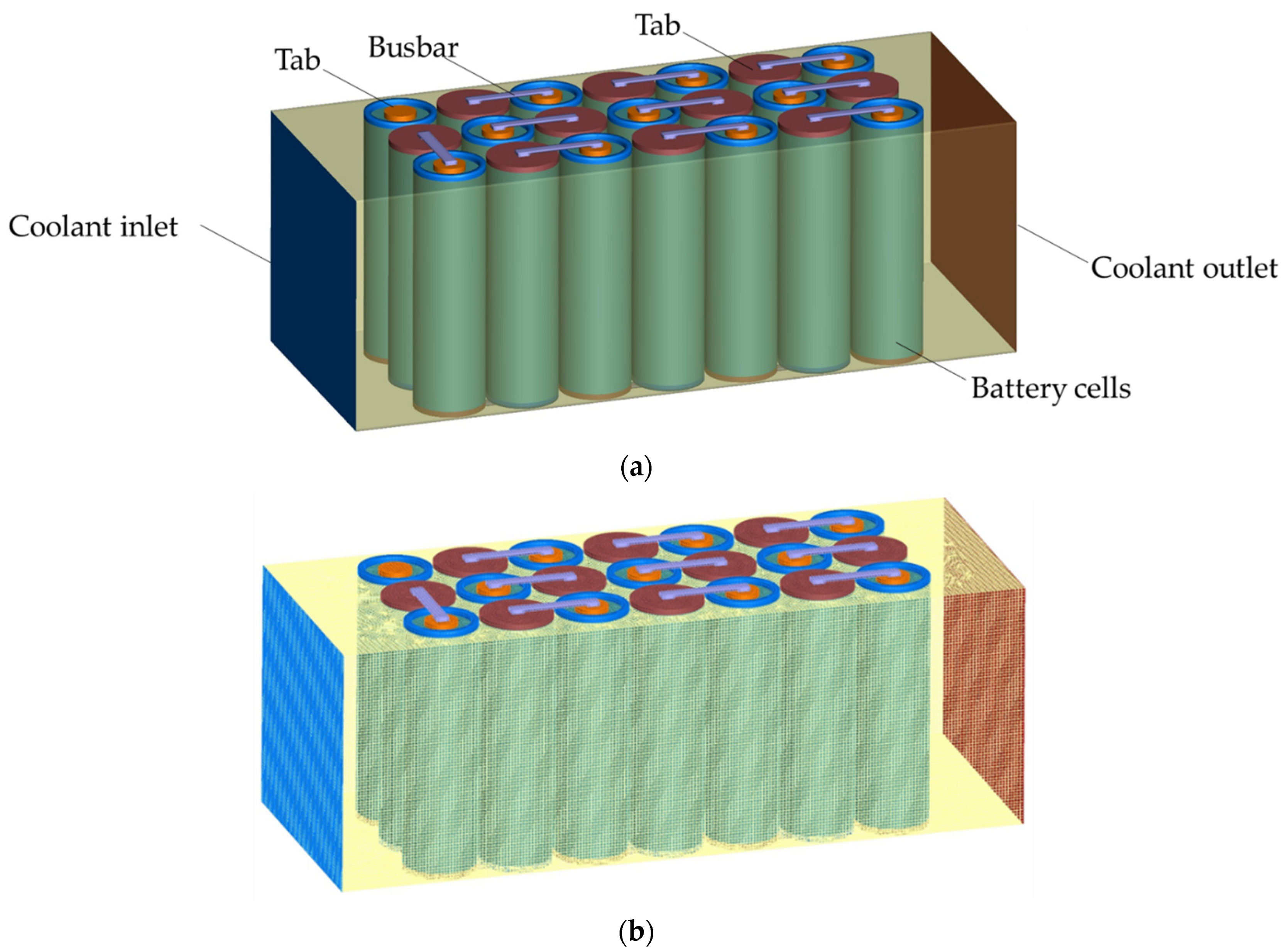
A battery pack consisting of 21 cylindrical lithium-ion cells connected in series was then simulated. The model and mesh of the cell pack is shown in 
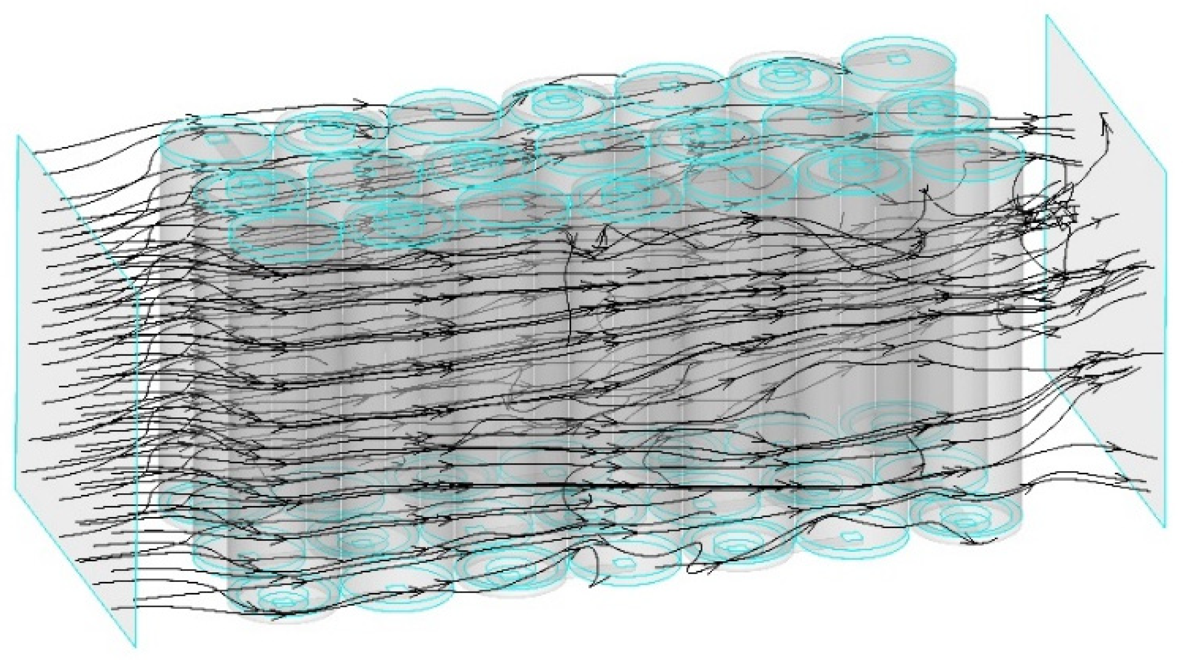
Figure 12. As shown in the figure, each lithium-ion battery has positive and negative electrode tabs, which are connected via busbar. When the battery pack adopts single-phase direct cooling by FC-72, FC-72 enters the flow path through the inlet, cools the battery by directly contacting the cylindrical cell successively, and converges at the outlet and flows out of the flow path. To illustrate the flow direction of the coolant, the flow path can be observed in Figure 13.
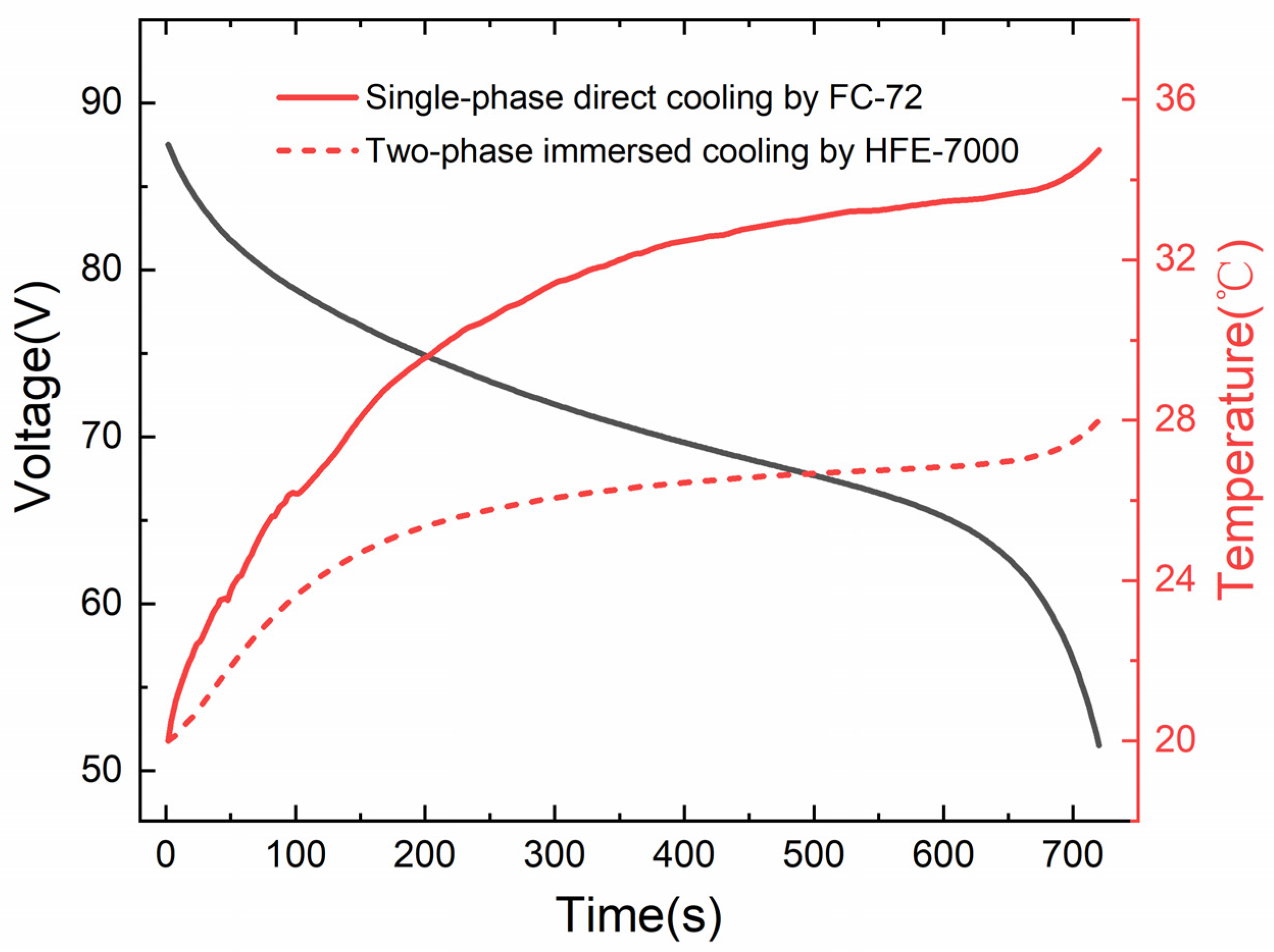
The voltage curve and maximum temperature curve of the lithium-ion battery pack under 5C (12.5 A) discharge are shown in Figure 14. In this model, the inlet velocity of FC-72 is 0.1 m/s and the initial temperature is 20 °C. As can be seen, when the battery adopts single-phase direct cooling by FC-72 or two-phase immersed cooling by HFE-7000, the maximum temperature of a cell pack under 5C rate discharging does not exceed 40 °C. Among them, when using single-phase direct cooling by FC-72, the maximum temperature of the cell pack reached 34.74 °C at the end of discharge, meanwhile, when using two-phase immersed cooling by HFE-7000, the maximum temperature of the cell pack is only 28 °C at the end of discharge. The temperature rise in this case is only 54.27% of that using single-phase direct cooling by FC-72. The pumping power for the FC-72 single-phase battery pack cooling is 0.19 W.
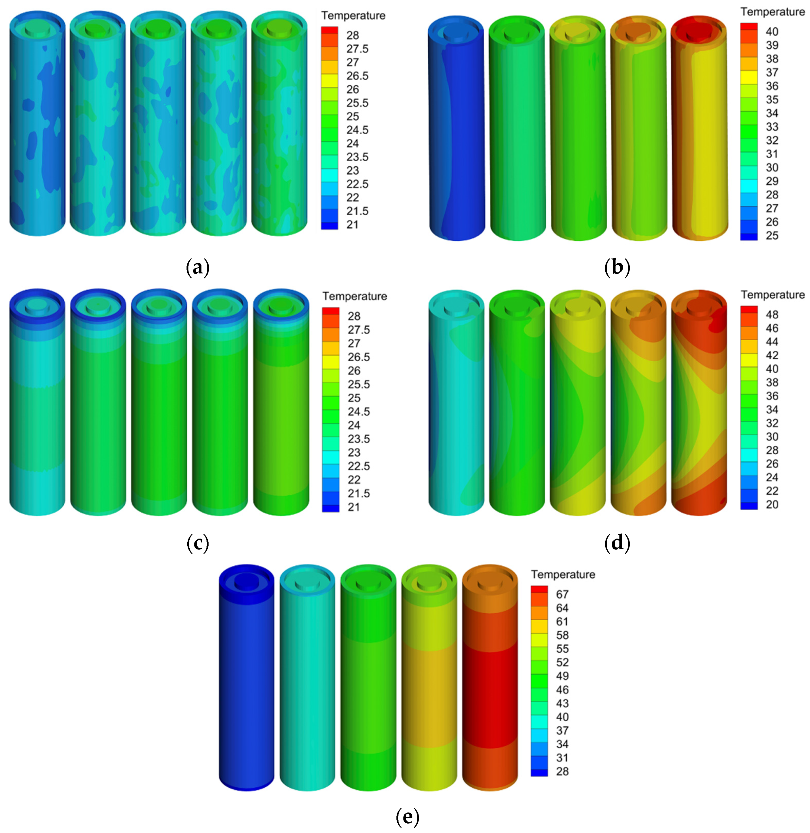
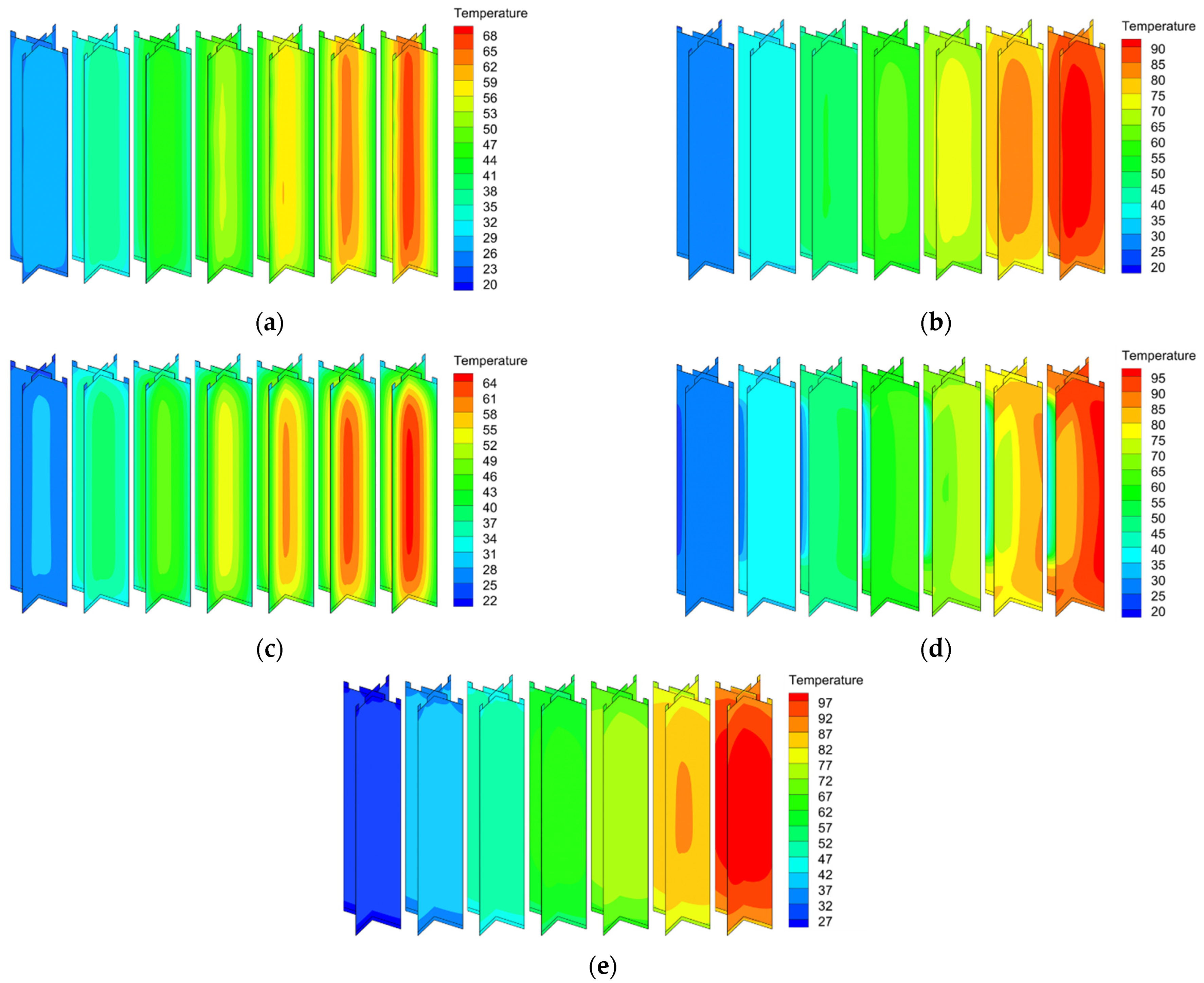
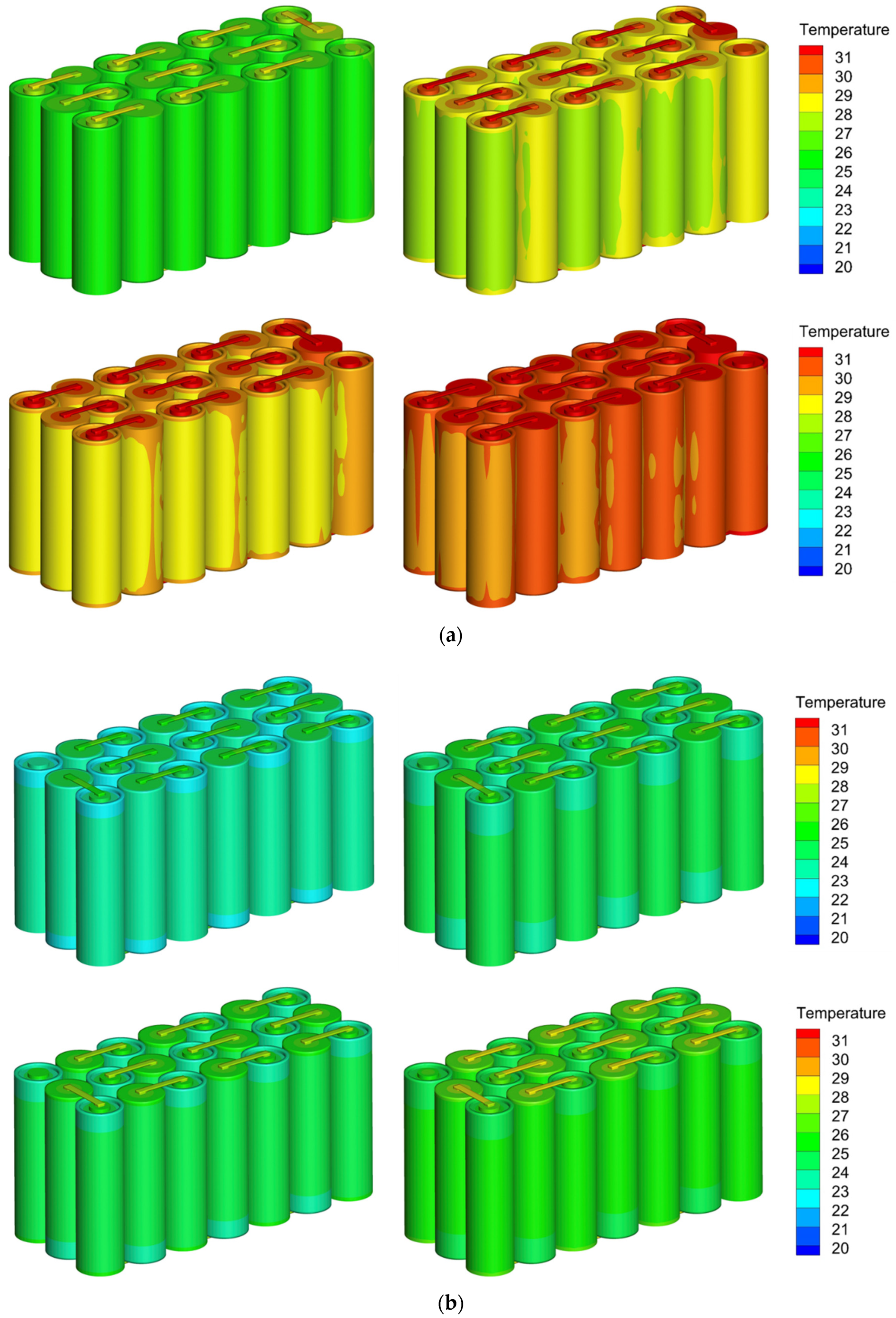
Figure 15 shows the temperature cloud variations of the 75 V lithium-ion battery pack at different depths of discharge under 5C rate discharging. It can be found that although using single-phase direct cooling by FC-72 can limit the maximum temperature of cell pack to less than 40 °C well at high C rate discharging, temperature non-uniformity still exists among different cells in the flow direction of the coolant despite the high flow rate. This is due to the fact that the cooling medium absorbs the heat released by the cell during operation in the process of flowing and then the temperature increases, that is, the temperature of upstream cooling medium is lower, while the temperature of downstream coolant is relatively higher. Therefore, the temperature of cell near the inlet is lower, while the temperature of cell near the outlet is relatively higher. However, as the flow rate in the modeling case is large, this temperature rise seems not significant. When the battery adopts two-phase immersed cooling by HFE-7000, the fluorinated liquid uses its own sensible or latent heat to absorb the heat generated by the battery during the discharge process, thus, the external cooling conditions for each cell within the battery pack are almost consistent and the temperature difference among different cells within the battery pack is almost zero.

5. Conclusions

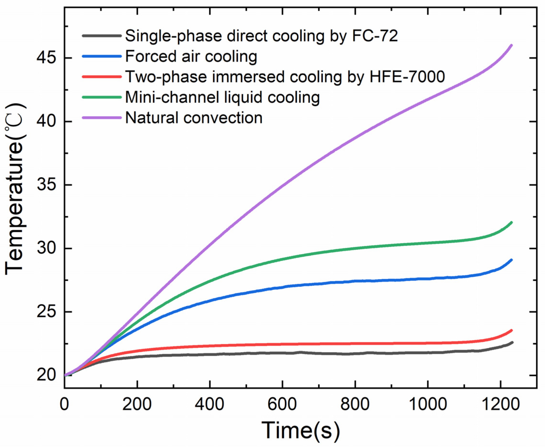
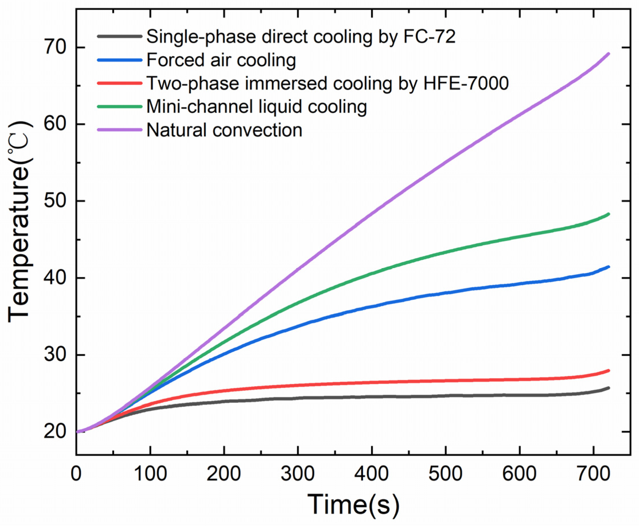
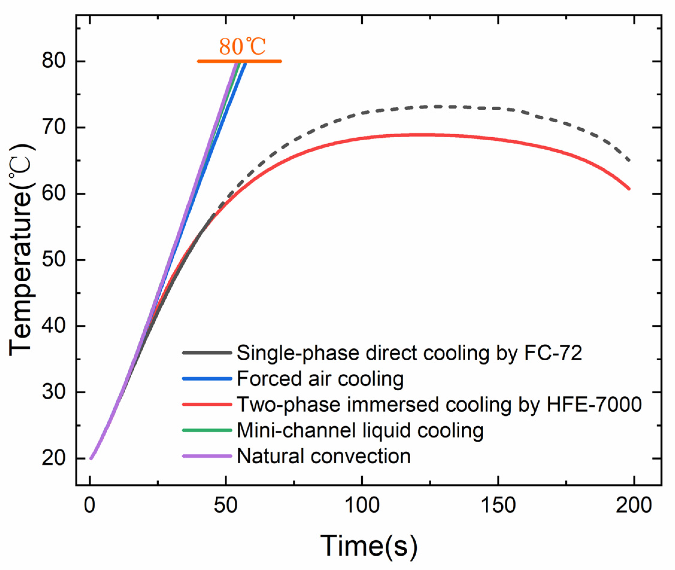
In this paper, a MSMD model was used to perform three-dimensional thermal simulations for a lithium-ion battery and lithium-ion battery pack cooled by different methods. Firstly, the effects of different cooling schemes on the temperature response of individual cell during discharge were studied under high C rate discharging. It was found that, when the battery adopts single-phase direct cooling by FC-72 or two-phase immersed cooling by HFE-7000, the maximum temperature of cell was limited to 30 °C under 5C rate discharging. When the battery uses natural convection, forced air cooling or mini-channel liquid cooling, the maximum temperature of the cell exceeded 40 °C. Then, when the battery was tested under dynamic load conditions, compared with natural convection, forced air cooling or mini-channel liquid cooling, the applications of single-phase direct cooling by FC-72 or two-phase immersed cooling by HFE-7000 can keep the temperature of the lithium battery relatively stable. Thirdly, under the condition of external short circuit of lithium-ion battery, the maximum temperature of the battery did not exceed 80 °C when applying single-phase direct cooling by FC-72 or two-phase immersed cooling by HFE-7000, which is the safe temperature range of lithium-ion batteries. When the battery uses natural convection, forced air cooling or mini-channel liquid cooling, the temperature of cell will reach 80 °C within 60 s, which will trigger battery thermal runaway.
For lithium-ion battery packs, when the battery adopts single-phase direct cooling by FC-72 or two-phase immersed cooling by HFE-7000, the maximum temperature of cell pack under 5C rate discharging can be suppressed to be lower than 40 °C. Compared with single-phase direct cooling by FC-72, using two-phase immersed cooling by HFE-7000 can better limit the maximum temperature rise of cell pack. In addition, for the instance of FC-72 single phase direct cooling, there is certain temperature difference between the cell located upstream and the cell located downstream in the flow direction of the cooling medium. On the other hand, when the battery uses two-phase immersed cooling by HFE-7000, the temperature difference among different cells within the battery pack is almost zero. To sum up, the two-phase immersed cooling of lithium batteries is pointed out to be a promising cooling method for batteries. It can limit the cell temperature rise under extremely fast discharging condition, even certain external shorting condition. Additionally, it can also help reduce the temperature temporal variations, thus, reducing the needs for battery temperature active control under dynamic load condition. The immersed cooling can also bring more uniform temperature in battery packs as indicated in this study. Although the potential advantages of immersed cooling of lithium-ion batteries are pointed out by simplified modeling in this work, more in-depth study of the heat transfer mechanisms and more advanced modeling method development for modeling battery immersed cooling still needs further exploration.

Author Contributions

Formal analysis, J.Z.; investigation, Y.L. (Yang Li); methodology, Z.Z. and M.B.; software, Y.L. (Yulong Li) and X.L.; supervision, Y.L. (Yubai Li) and Y.S.; validation, L.H.; writing—original draft, Y.L. (Yang Li) and Z.Z.; writing—review and editing, J.Z., L.H., M.B., Y.L. (Yulong Li), X.L., Y.L. (Yubai Li) and Y.S. All authors have read and agreed to the published version of the manuscript.

Funding

This research was funded by the National Natural Science Foundation of China (Grant No. 52106226, 51876027, 51806028), and Fundamental Research Funds for the Central Universities (Grant No. DUT20RC(3)095, DUT20JC21).

Institutional Review Board Statement

Not applicable.

Informed Consent Statement

Not applicable.

Data Availability Statement

Not applicable.

Conflicts of Interest

The authors declare no conflict of interest.

References

  1. Liu, H.; Wei, Z.; He, W.; Zhao, J. Thermal issues about Li-ion batteries and recent progress in battery thermal management systems: A review. Energy Convers. Manag. 2017, 150, 304–330. [Google Scholar] [CrossRef]
  2. Kim, J.; Oh, J.; Lee, H. Review on battery thermal management system for electric vehicles. Appl. Therm. Eng. 2019, 149, 192–212. [Google Scholar] [CrossRef]
  3. Wu, W.; Wang, S.; Wu, W.; Chen, K.; Hong, S.; Lai, Y. A critical review of battery thermal performance and liquid based battery thermal management. Energy Convers. Manag. 2019, 182, 262–281. [Google Scholar] [CrossRef]
  4. Bandhauer, T.M.; Garimella, S.; Fuller, T.F. A critical review of thermal issues in lithium-ion batteries. J. Electrochem. Soc. 2011, 158, R1–R25. [Google Scholar] [CrossRef]
  5. Zhou, L.; Zheng, Y.; Ouyang, M.; Lu, L. A study on parameter variation effects on battery packs for electric vehicles. J. Power Sources 2017, 364, 242–252. [Google Scholar] [CrossRef]
  6. Wang, Q.; Ping, P.; Zhao, X.; Chu, G.; Sun, J.; Chen, C. Thermal runaway caused fire and explosion of lithium ion battery. J. Power Sources 2012, 208, 210–224. [Google Scholar] [CrossRef]
  7. Feng, X.; Pan, Y.; He, X.; Wang, L.; Ouyang, M. Detecting the internal short circuit in large-format lithium-ion battery using model-based fault-diagnosis algorithm. J. Energy Storage 2018, 18, 26–39. [Google Scholar] [CrossRef]
  8. Abaza, A.; Ferrari, S.; Wong, H.K.; Lyness, C.; Moore, A.; Weaving, J.; Blanco-Martin, M.; Dashwood, R.; Bhagat, R. Experimental study of internal and external short circuits of commercial automotive pouch lithium-ion cells. J. Energy Storage 2018, 16, 211–217. [Google Scholar] [CrossRef]
  9. Zhao, W.; Luo, G.; Wang, C.Y. Modeling internal shorting process in large-format Li-ion cells. J. Electrochem. Soc. 2015, 162, A1352–A1364. [Google Scholar] [CrossRef] [Green Version]
  10. Park, H. A design of air flow configuration for cooling lithium ion battery in hybrid electric vehicles. J. Power Sources 2013, 239, 30–36. [Google Scholar] [CrossRef]
  11. Yu, X.; Lu, Z.; Zhang, L.; Wei, L.; Cui, X.; Jin, L. Experimental study on transient thermal characteristics of stagger-arranged lithium-ion battery pack with air cooling strategy. Int. J. Heat Mass Transf. 2019, 143, 118576. [Google Scholar] [CrossRef]
  12. Wei, Y.; Agelin-Chaab, M. Experimental investigation of a novel hybrid cooling method for lithium-ion batteries. Appl. Therm. Eng. 2018, 136, 375–387. [Google Scholar] [CrossRef]
  13. Menale, C.; D’Annibale, F.; Mazzarotta, B.; Bubbico, R. Thermal management of lithium-ion batteries: An experimental investigation. Energy 2019, 182, 57–71. [Google Scholar] [CrossRef]
  14. Bai, F.; Chen, M.; Song, W.; Feng, Z.; Li, Y.; Ding, Y. Thermal management performances of PCM/water cooling-plate using for lithium-ion battery module based on non-uniform internal heat source. Appl. Therm. Eng. 2017, 126, 17–27. [Google Scholar] [CrossRef]
  15. Tran, T.; Harmand, S.; Desmet, B.; Filangi, S. Experimental investigation on the feasibility of heat pipe cooling for HEV/EV lithium-ion battery. Appl. Therm. Eng. 2014, 63, 551–558. [Google Scholar] [CrossRef]
  16. Deng, Y.; Feng, C.; Jiaqiang, E.; Zhu, H.; Chen, J.; Wen, M.; Yin, H. Effects of different coolants and cooling strategies on the cooling performance of the power lithium ion battery system: A review. Appl. Therm. Eng. 2018, 142, 10–29. [Google Scholar] [CrossRef]
  17. Wang, Y.-F.; Wu, J.-T. Thermal performance predictions for an HFE-7000 direct flow boiling cooled battery thermal management system for electric vehicles. Energy Convers. Manag. 2020, 207, 112569. [Google Scholar] [CrossRef]
  18. Wroblewski, D.E.; Joshi, Y. Liquid immersion cooling of a substrate-mounted protrusion in a three-dimensional enclosure: The effects of geometry and boundary conditions. J. Heat Transf. 1994, 116, 112–119. [Google Scholar] [CrossRef]
  19. Ei-Genk, M.S. Immersion cooling nucleate boiling of high power computer chips. Energy Convers. Manag. 2012, 53, 205–218. [Google Scholar] [CrossRef]
  20. Van Gils, R.W.; Danilov, D.; Notten, P.H.L.; Speetjens, M.F.M.; Nijmeijer, H. Battery thermal management by boiling heat-transfer. Energy Convers. Manag. 2014, 79, 9–17. [Google Scholar] [CrossRef]
  21. Zhou, H.; Dai, C.; Liu, Y.; Fu, X.; Du, Y. Experimental investigation of battery thermal management and safety with heat pipe and immersion phase change liquid. J. Power Sources 2020, 473, 228545. [Google Scholar] [CrossRef]
  22. Wang, Q.; Jiang, B.; Yan, Y. A critical review of thermal management models and solutions of lithium-ion batteries for the development of pure electric vehicles. Renew. Sustain. Energy Rev. 2016, 64, 106–128. [Google Scholar] [CrossRef]
  23. Karimi, G.; Li, X. Thermal management of lithium-ion batteries for electric vehicles. Int. J. Energy Res. 2013, 37, 13–24. [Google Scholar] [CrossRef]
  24. Kalkan, O.; Celen, A.; Bakirci, K. Experimental and numerical investigation of the LiFePO4 battery cooling by natural convection. J. Energy Storage 2021, 40, 102796. [Google Scholar] [CrossRef]
  25. ANSYS, Inc. Ansys Fluent 18.1 Advanced Add-On Module Guide Documentation; ANSYS, Inc.: Canonsburg, PA, USA, 2017. [Google Scholar]
  26. Kwon, K.H.; Shin, C.B.; Kang, T.H.; Kim, C.S. A two-dimensional modeling of a lithium-polymer battery. J. Power Sources 2016, 163, 151–157. [Google Scholar] [CrossRef]
  27. Xie, J.; Ge, Z.; Zang, M.; Wang, S. Structural optimization of lithium-ion battery pack with forced air cooling system. Appl. Therm. Eng. 2017, 126, 583–593. [Google Scholar] [CrossRef]
  28. Yang, N.; Zhang, X.; Li, G.; Hua, D. Assessment of the forced air-cooling performance for cylindrical lithium-ion battery packs: A comparative analysis between aligned and staggered cell arrangements. Appl. Therm. Eng. 2015, 80, 55–65. [Google Scholar] [CrossRef]
  29. Saw, L.H.; Ye, Y.; Tay, A.A.O.; Chong, W.T.; Kuan, S.H.; Yew, M.C. Computational fluid dynamic and thermal analysis of lithium-ion battery pack with air cooling. Appl. Energy 2016, 177, 783–792. [Google Scholar] [CrossRef]
  30. Wang, T.; Tseng, K.J.; Zhao, J.; Wei, Z. Thermal investigation of lithium-ion battery module with different cell arrangement structures and forced air-cooling strategies. Appl. Energy 2014, 134, 229–238. [Google Scholar] [CrossRef]
  31. Zhou, H.; Zhou, F.; Xu, L.; Kong, J.; Yang, Q. Thermal performance of cylindrical Lithium-ion battery thermal management system based on air distribution pipe. Int. J. Heat Mass Transf. 2019, 131, 984–998. [Google Scholar] [CrossRef]
  32. Li, X.; Zhao, J.; Yuan, J.; Duan, J.; Liang, C. Simulation and analysis of air cooling configurations for a lithium-ion battery pack. J. Energy Storage 2021, 35, 102270. [Google Scholar] [CrossRef]
  33. Huo, Y.; Rao, Z.; Liu, X.; Zhao, J. Investigation of power battery thermal management by using mini-channel cold plate. Energy Convers. Manag. 2015, 89, 387–395. [Google Scholar] [CrossRef]
  34. Wu, C.; Wang, Z.; Bao, Y.; Zhao, J.; Rao, Z. Investigation on the performance enhancement of baffled cold plate based battery thermal management system. J. Energy Storage 2021, 41, 102882. [Google Scholar] [CrossRef]
  35. Panchal, S.; Khasow, R.; Dincer, I.; Agelin-Chaab, M.; Fraser, R.; Fowler, M. Thermal design and simulation of mini-channel cold plate for water cooled large sized prismatic lithium-ion battery. Appl. Therm. Eng. 2017, 122, 80–90. [Google Scholar] [CrossRef]
  36. Li, Y.; Zhou, Z.; Wu, W.-T. Three-dimensional thermal modeling of Li-ion battery cell and 50 V Li-ion battery pack cooled by mini-channel cold plate. Appl. Therm. Eng. 2019, 147, 829–840. [Google Scholar] [CrossRef]
  37. Cao, W.; Zhao, C.; Wang, Y.; Dong, T.; Jiang, F. Thermal modeling of full-size-scale cylindrical battery pack cooled by channeled liquid flow. Int. J. Heat Mass Transf. 2019, 138, 1178–1187. [Google Scholar] [CrossRef]
  38. Tan, X.; Lyu, P.; Fan, Y.; Rao, J.; Ouyang, K. Numerical investigation of the direct liquid cooling of a fast-charging lithium-ion battery pack in hydrofluoroether. Appl. Therm. Eng. 2021, 196, 117279. [Google Scholar] [CrossRef]
  39. Patil, M.S.; Seo, J.-H.; Lee, M.-Y. A novel dielectric fluid immersion cooling technology for Li-ion battery thermal management. Energy Convers. Manag. 2021, 229, 113715. [Google Scholar] [CrossRef]
  40. Liaw, B.Y.; Nagasubramanian, G.; Jungst, R.G.; Doughty, D.H. Modeling of lithium ion cells—A simple equivalent-circuit model approach. Solid State Ion. 2004, 175, 835–839. [Google Scholar]
Figure 1. Schematic of (a) geometry of natural convection and two-phase immersed cooling by HFE-7000; (b) mesh of natural convection and two-phase immersed cooling by HFE-7000; (c) geometry of mini-channel liquid cooling; (d) mesh of mini-channel liquid cooling.
Energies 14 06986 g001
Figure 2. Schematic of (a) geometry of forced air cooling and single-phase direct cooling by FC-72; (b) mesh of forced air cooling and single-phase direct cooling by FC-72.
Energies 14 06986 g002
Figure 3. Comparison of modeling data and experimental data under two C rate discharging condition.
Energies 14 06986 g003
Figure 4. Maximum temperature curves under five cooling conditions at 3C discharge.
Energies 14 06986 g004
Figure 5. Maximum temperature curves under five cooling conditions at 5C discharge.
Energies 14 06986 g005
Figure 6. Maximum temperature clouds under (a) single-phase direct cooling by FC-72; (b) forced air cooling; (c) two-phase immersed cooling by HFE-7000; (d) mini-channel liquid cooling; (e) natural convection.
Energies 14 06986 g006
Figure 7. The (a) current input and (b) voltage response for dynamic load condition.
Energies 14 06986 g007
Figure 8. Temperature response of a single cell under five cooling schemes during the dynamic load cycle.
Energies 14 06986 g008
Figure 9. Voltage response under the condition of external short circuit.
Energies 14 06986 g009
Figure 10. Temperature response under the condition of external short circuit.
Energies 14 06986 g010
Figure 11. Maximum temperature clouds under external short circuit conditions by the cooling scheme of (a) single-phase direct cooling by FC-72; (b) forced air cooling; (c) two-phase immersed cooling by HFE-7000; (d) mini-channel liquid cooling; (e) natural convection.
Energies 14 06986 g011
Figure 12. Schematic of (a) geometry of the cell pack under single-phase direct cooling by FC-72; (b) mesh of the cell pack under single-phase direct cooling by FC-72.
Energies 14 06986 g012
Figure 13. Flow path of FC-72.
Energies 14 06986 g013
Figure 14. The voltage curve and maximum temperature curve of a lithium-ion battery pack under 5C.
Energies 14 06986 g014
Figure 15. The temperature cloud variation of a cell pack under (a) single-phase direct cooling by FC-72; (b) two-phase immersed cooling by HFE-7000.
Energies 14 06986 g015
Table 1. Parameters of the cell characteristics and specific parameters of the five cooling methods.
QuantityValue
Diameter (mm)18.33 ± 0.07
Height (mm)64.85 ± 0.15
Weight (g)43.8
Nominal voltage (V)3.65
Nominal capacity (Ah)2.5
Cold blade thickness (mm)5
Coolant channel thickness (mm)3
Coolant channel width (mm)4
Table 2. Electrical and thermal parameters used in simulation.
Materialρ (kg m−3)c (J kg−1 K−1)k (W m−1 K−1)µ (Pa s)σ+ (S/m)σ (S/m)
Battery270012003 1.19 × 1069.83 × 105
Aluminum2719871202.4
Air1.2251006.430.02421.79 × 10−5
Water998.241820.61.03 × 10−3
FC-72168011000.0663.8 × 10−4
Publisher’s Note: MDPI stays neutral with regard to jurisdictional claims in published maps and institutional affiliations.

