Abstract
Throughout the world, wind energy is widely distributed as one of the most universal energy sources in nature, containing a gigantic reserve of renewable and green energy. At present, the main way to capture wind energy is to use an electromagnetic generator (EMG), but this technology has many limitations; notably, energy conversion efficiency is relatively low in irregular environments or when there is only a gentle breeze. A triboelectric nanogenerator (TENG), which is based on the coupling effect of triboelectrification and electrostatic induction, has obvious advantages for mechanical energy conversion in some specific situations. This review focuses on wind energy harvesting by TENG. First, the basic principles of TENG and existing devices’ working modes are introduced. Second, the latest research into wind energy-related TENG is summarized from the perspectives of structure design, self-power sensors and systems. Then, the potential for large-scale application and hybridization with other energy harvesting technologies is discussed. Finally, future trends and remaining challenges are anticipated and proposed.
1. Introduction
On account of the exponential growth of fossil fuel consumption, energy supplies will continue to face severe challenges for as long as emissions of greenhouse gases contribute to global warming [1,2]. Therefore, looking for a renewable, environmentally friendly and economical source of energy has become the focus of sustainable development. Among all types of renewable energy sources, wind energy has significant advantages in terms of wide distribution, abundance, sustainability and pollution-free methods. Traditionally, the method of converting wind energy into electric energy was based on the principle of electromagnetic induction and turbine structure. However, most of the structures based on this method should be constructed with bulky and heavy magnet components and erected in places where powerful winds are common. To date, these types of wind generators have not been fully utilized in distributed miniature power supply and wind energy resources with low speed. Moreover, due to the uncontrollable speed and direction of wind energy [3,4,5,6], our daily life is concentrated as far away as possible from wind-rich areas, leading to wind power generation equipment being dislocated from its peak consumption areas. In view of the above constraints, new methods are needed to realize efficient wind energy acquisition and local utilization.
In 2012, Professor Z.L. Wang proposed a new energy harvesting method known as a triboelectric nanogenerator (TENG) [7]. It is based on the coupling effect of contact electrification and electrostatic induction [8]. TENG has many unique advantages such as simple manufacturing, low cost, a rich selection of composition materials and structure, a high power density and a high energy conversion efficiency in low frequency ranges [9,10,11]. TENG is universal in mechanical energy harvesting and has been applied to capture energy from a variety of sources, such as human motion [12,13], rotation [14], wind [15,16,17], water waves [18], etc. Moreover, TENG has proven itself to be a sustainable technology for wind energy collection by diversified functional and structural designs. For example, Zaw et al. [19] proposed a wind-driven triboelectric nanogenerator (Wind-TENG) based on the fluttering of a polytetrafluoroethylene (PTFE) belt that could sensitively harvest breeze energy at a wind speed of 1.5 m/s; the maximum output power density of Wind-TENG under a load resistance of 5 MΩ was 0.64 mW/m2. A flexible waterproof dual-mode textile triboelectric nanogenerator (TENG) was reported by Gang et al. for harvesting multiple energies including wind, rain and human motion [20]. Beyond that, TENG is also applied in portable electronic devices, active sensors, wireless sensor networks, implanted biomedical devices and other fields [21,22,23,24,25,26,27,28,29].
In short, TENGs have made great achievements in wind power harvesting. It is therefore necessary to conduct a comprehensive and systematic review of their recent progress. Regarding the structural design of TENGs, this review provides a summary of the latest developments and points out future prospects in the field of TENG as a wind-energy harvester. We first introduce the working principle of TENG and its operating mode. Then, a systematical comparison of the distinction between TENG and EMG devices is undertaken. Additionally, recent innovative progress using TENG for wind energy harvesting is examined from the perspective of material and structure designs. Finally, some remaining challenges and opportunities for the future development of TENG for wind energy harvesting are discussed.
2. Fundamentals of TENG
2.1. Mechanism of TENG
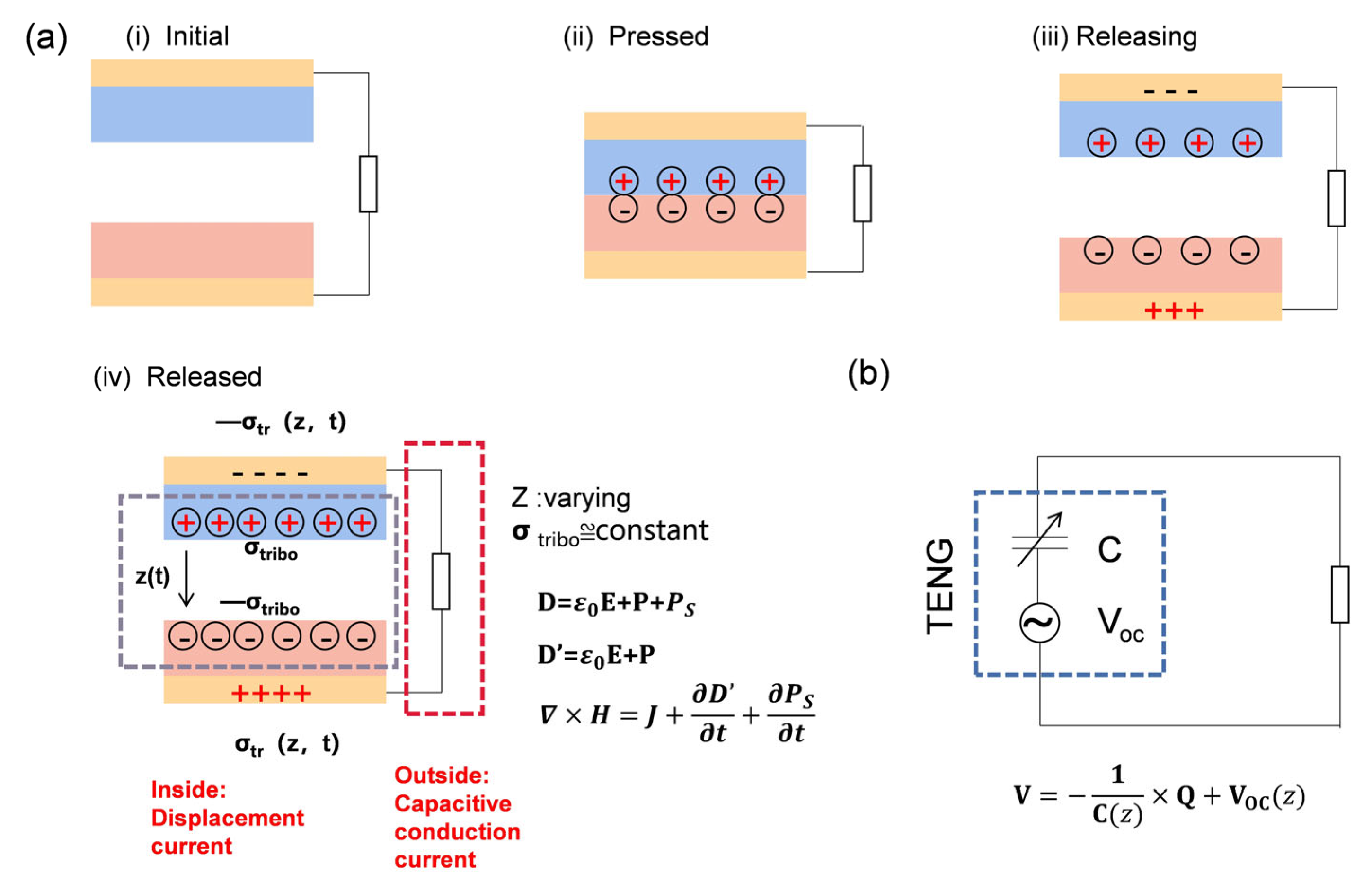
Combining triboelectrification and electrostatic induction, TENG can covert mechanical energy from the ambient environment into electricity. Figure 1a shows the working mechanism of TENG with a vertical contact separation mode. Two different electronegative dielectric films (d1 and d2 are defined as the thicknesses of dielectrics 1 and 2, respectively) are employed as the top and bottom tribo-layers of the assembled device structure. In the initial state (Figure 1a(i)), suppose that no triboelectric charges exist on the surface of the two dielectric layers. When an external force is applied on the device, the gap distance z(t) between the two dielectric layers will decrease until in full contact (Figure 1a(ii)). At this moment, one dielectric layer generates negative static charges, and the other layer produces an equivalent quantity of positive static charges due to the triboelectrification effect. It is assumed that the triboelectric charge is uniformly distributed on the surface of the two dielectric films, and the corresponding surface charge density is σtribo. Once the applied force is removed (Figure 1a(iii)), the gap distance z(t) begins to increase, resulting in a potential difference between the top electrode and the bottom electrode. In order to balance this potential difference caused by triboelectric charge, electrons flow from the bottom electrode to top electrode through an external circuit to generate pulse current. In this process, mechanical energy is converted into electricity, and the accumulated charge density on the two electrodes can be expressed as σtr (z,t) and −σtr (z,t), respectively (Figure 1a(iv)). When the external force is applied to the device again, electrons on the electrodes will flow back to compensate the potential difference. By repeating this operation cycle, a continuous alternating current output can be obtained.
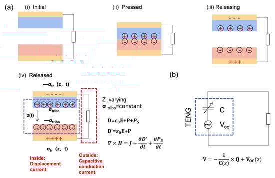
Figure 1.
Theoretical models of TENG: (a) schematic illustration of the first TENG and its operation cycle. (b) The equivalent electrical circuit model of TENG.
The fundamental physics of TENG originate from Maxwell’s basic equations [30]. One of Maxwell’s basic equations is
where H is the magnetizing field, J is the free electric current density, D is the electric displacement vector and . Where P is the polarization field, is the permittivity in vacuum and E is the presence of an electric field.
The Maxwell’s displacement current is introduced as
In a general isotropic medium, ,. Here, is the dielectric constant of a dielectric. The displacement current becomes:
The existence of displacement current not only reveals the connection between electrical and magnetic phenomena, but also gives the birth of electromagnetic wave, laying the physical foundation of wireless communication.
In the case of TENG, the triboelectric charge is generated by the physical contact between two different materials. In order to explain the contribution of electrostatic charges caused by the contact electrification in Maxwell’s equation, an additional term PS is added in D by Wang in 2017 [30,31], which is the polarization of surface charges generated by a mechanical trigger, and different from the dielectric polarization P induced by the electric field, that is
Substituting Equation (4) into Maxwell’s equations, and defining
Then, Equation (1) can be transformed into
Therefore, in a media with the presence of surface polarization charges, such as piezoelectric materials or triboelectric materials, the displacement current should consider the influence of the polarization field generated by the electrostatic charge on the surface of the material. Then, the Maxwell’s displacement current can be represented as
The first term refers to a time-varying electric field in the vacuum, while the second term presents the contribution of surface polarization, which is the first principle theory of TENG.
The basic model of a contact-separation-mode triboelectric nanogenerator is shown in Figure 1a. The displacement current can be calculated as
For TENG, it is referred to as the capacitive conduction. The oppositely charged surface with varying gap distance can be regarded as a capacitor with varying capacitance [31,32]. The current of external the circuit can be written as
where Q is the stored charges in the capacitor.
Equation (8) is equivalent to Equation (7). Based on the capacitor model, the corresponding output voltage of TENG is
where VOC(z) is the open-circuit voltage of TENG (Figure 1b).
2.2. Four Basic Working Modes of TENG
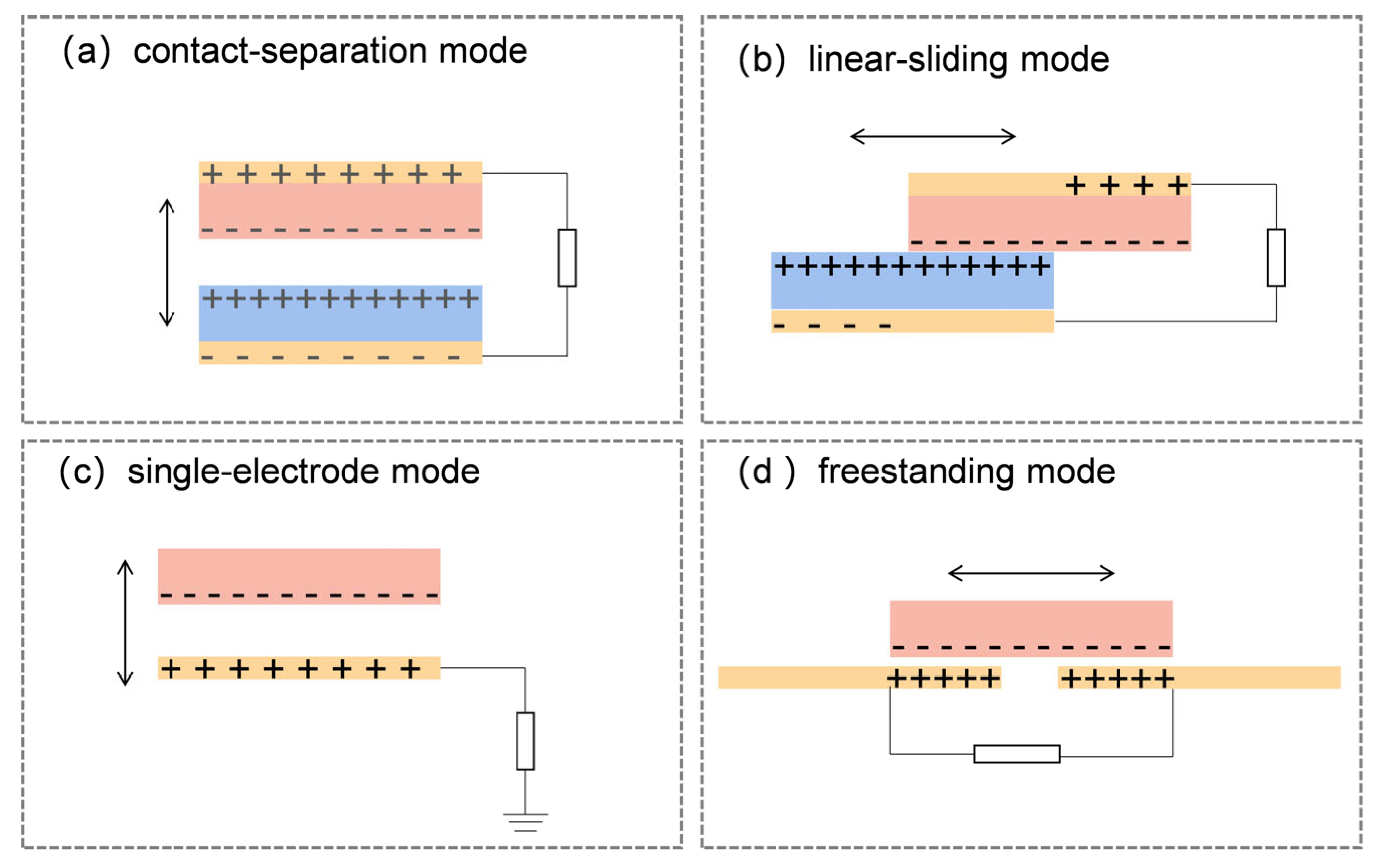
According to the device configuration, four basic working modes of TENG are divided, including vertical contact-separation (CS) mode, linear-sliding (LS) mode, single-electrode (SE) mode and freestanding (FT) mode, as shown in Figure 2 [32]. Among them, the most basic structure is CS mode TENG, which is composed of two different dielectric layers and metal electrodes on the back. Under the action of external force, the two dielectric films contact and separate from each other. Thus, a potential change is generated between the electrodes. However, CS mode TENG has the advantages of a convenient fabrication and a simple structure; it requires room to realize fully vertical separation and contact, leading to packaging difficulties. For LS mode TENG, it is actually evolved from the vertical CS mode TENG, and its structure is very similar to that of the CS mode, as shown in Figure 2b. The only difference is that the two dielectric layers are always in close contact in the case of external force, which makes LS mode TENG more suitable for device integration. However, the unavoidable problem of this mode is material abrasion, directly affecting the durability and energy conversion efficiency of the device. The SE mode TENG (Figure 2c) is often used when two triboelectric films are not easily connected to each other. Compared with CS mode TENG, it has only one electrode, and the electrode is connected to the ground through load. It has the same contact electrification process with the previous two working modes. Although SE mode TENG has better versatility and applicability, the electrical output of this device is half as much as that of TENG with two electrodes. The fourth structure of TENG is depicted in Figure 2d. The FS mode TENG evolves from the SE mode TENG. A pair of symmetrical electrodes are placed under the dielectric layer, and the electrodes are connected with the load. The dielectric layer close to or far from the electrodes produces an asymmetrical charge distribution on the electrode, which causes the electrons flow between the two electrodes to balance the potential distribution and generates an alternating current electrical signal. In such a structural design, the dielectric film does not need to contact the electrodes directly; therefore, material abrasion can be greatly reduced.
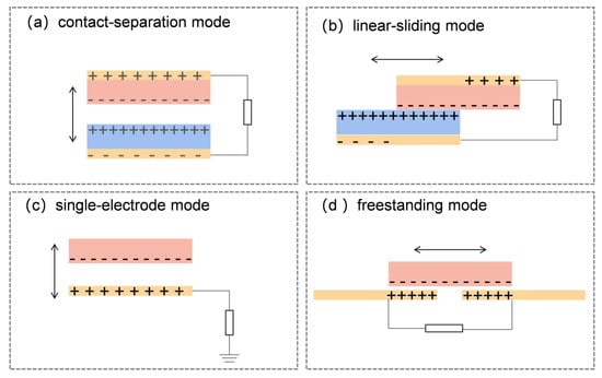
Figure 2.
Four working modes of TENG: (a) vertical CS mode; (b) LS mode; (c) SE mode; (d) FS mode.
2.3. Comparison between TENG and EMG
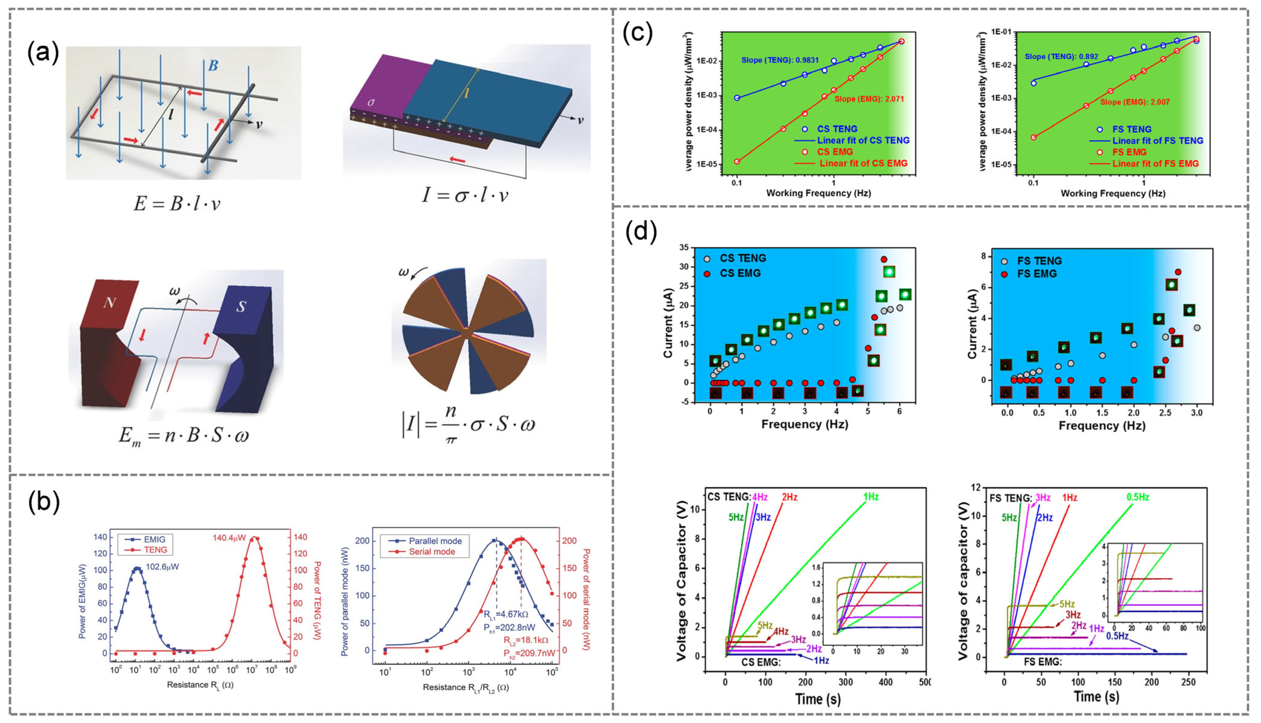
EMG is a traditional energy collection technology, and its principle is based on an electromagnetic induction phenomenon. As presented in Figure 3a, when a conductor moves in the magnetic field in a direction perpendicular to the magnetic induction line, it cuts the magnetic induction line and changes the area enclosed by the circuit. Hence, a motional electromotive force will be generated at both ends of the conductor that are perpendicular to the magnetic field and the direction of motion. Unlike EMG, TENG transforms mechanical energy into electrical energy based on the triboelectrification and electrostatic induction. However, the former depends on magnetic flux density and the latter relies on triboelectric charge density. When the two basic models are rotating EMG and rotating TENG, their governing equations can still be analogous. In Figure 3b, Zhang et al. not only compares the maximum output power of TENG and EMG under different loads, but also investigates the relationship between the output power of TENG and EMG and external load resistance in series and parallel modes. The results in Figure 3c show the correlation between average power density and frequency of EMG and TENG. The output power density of EMG is directly proportional to the square of the working frequency (f2), while the output power density of TENG is directly proportional to the working frequency (f). From Figure 3d, in a low frequency range, the output current of TENG is higher than that of EMG with the same operating mode. To sum up, TENG’s working mechanism has significant advantages in terms of its light weight, small size, low cost and higher energy conversion efficiency in a low working frequency.
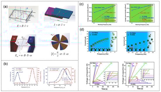
Figure 3.
A comparison between EMG and TENG: (a) theoretical comparison of EMG and TENG (reproduced with permission [33]. Copyright 2014, Advanced Materials). (b) Output power comparison of the rotating EMG and TENG in different cases (reproduced with permission [33]. Copyright 2014, Advanced Materials). (c) The average power densities of the CS mode and FS mode devices at low frequency (reproduced with permission [34]. Copyright 2016, ACS Nano). (d) The current of the CS mode and FS mode devices passing through LED at low frequency and output performance compared to CS mode and FS mode of EMG and TENG at low frequency (reproduced with permission [34]. Copyright 2016, ACS Nano).
3. Wind Energy Harvesting by TENG
3.1. Device Design Based on Wind Wheel Structure
Wind energy is a clean and rich source of renewable energy that plays an important role in power systems. In recent decades, the most common form of wind power technology has been based on a complex wind wheel structure, which requires a high installation height and works with a high starting wind speed [35,36], thus limiting its ability to collect wind energy, especially breeze energy; however, the emerging TENG [37] has the characteristics of a low working frequency, low cost, diverse material selection and small size, and therefore has great potential in the field of wind energy collection. Wind wheel-based TENG (WD-TENG) can be divided into several types in terms of structure [38,39]. These structures are discussed below.
Figure 4a [40] introduces a wind wheel TENG based on a scaly structure with unique advantages at a low rotation speed. When the rotation speed is 120 rpm, it can produce a maximum short-circuit current of 78 μA and an instantaneous power density of 2.54 W/m2. After charging the LiFePO4-Li battery for 30 min, the discharge capacity reaches 0.1 mAh, with the TENG operating at 120 rpm. However, the TENG in Figure 4a can only move in one direction (clockwise or counterclockwise). As such, Xie et al. proposed a bidirectional rotating TENG with blades, as shown in Figure 4b [41]. By mixing the traditional wind cup and rotating structure, the flexible polytetrafluoroethylene (PTFE) thin film on the rotor blade can continuously sweep through the Al plate so as to realize the continuous contact sliding separation between two charged surfaces. Based on this design, the open-circuit voltage is 250 V, the short-circuit current is 0.25 mA and the maximum power output is 62.5 mW when the wind speed is 15 m/s. Then, the direct contact of tribo-materials is usually required for the operation of TENG, which inevitably reduces the wear resistance of the device. In order to solve this problem, Li et al. put forward a design method to improve the stability of TENG by the automatic transition between a contact state and a non-contact working state. In Figure 4c [42], the structure can be divided into two main parts, including a rotating inner bucket connected to the rotor of the TENG disc and a fixed outer bucket connected with the stator of the TENG. In this structure, the contact mode of TENG can be automatically converted to a non-contact mode with an increase in wind speed. This automatic conversion is achieved by generating two opposite forces in the moving part of the TENG. One is the thrust to pull the rotor away from the stator from the connecting plate and the spring at the bottom of the inner cylinder, and the other is the force to push the stator and rotor together. In addition, the tension needs to be positively correlated with the moving speed of the moving parts of the TENG, and the rotor and stator are pushed into contact at a lower moving speed. However, at higher wind speeds, the accelerated rotation of the blade provides a greater driving force for the vertical separation of the rotor and stator. These results show that the TENG can work in a non-contact mode without material wear and can occasionally switch to a contact mode for surface charging. The automatic mode conversion grants TENG significant improvements in terms of robustness and practicability. As shown in Figure 4d [43], the coaxial rotating freestanding triboelectric nanogenerator (CRF-TENG) consists of two parts-one is the stator fixed on the bracket and the other is the hollow tube rotator. At a rotational speed of 900 rpm, CRF-TENG generates an open-circuit voltage of 650 V and a short-circuit current of 50 μA.
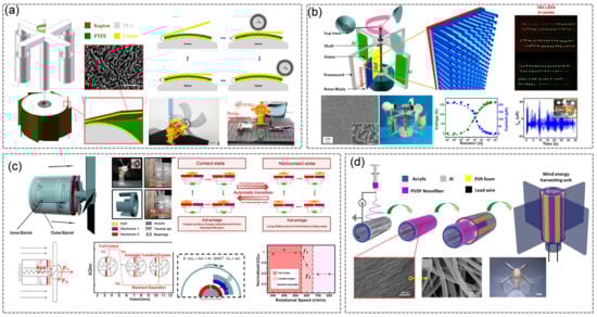
Figure 4.
Rotary-based mechanism: (a) CS-mode TENG with single direction rotation (reproduced with permission [40]. Copyright 2018, Nano Research). (b) CS-mode TENG with double direction rotation (reproduced with permission [41]. Copyright 2013, ACS Nano). (c) FS-mode TENG through automatic transition between contact and noncontact working states (reproduced with permission [42]. Copyright 2015, ACS Nano). (d) Coaxial rotatory FS-mode TENG (reproduced with permission [43]. Copyright 2018, Nano Energy).
3.2. Device Design Based on Wind-Induced Vibration Mode
The wind-induced vibration modes mainly include fluttering [44,45], galloping [46,47] and vortex-induced vibration (VIV) [48], all of which are designed to harvest wind energy. As illustrated in Figure 5a [49], the TENG array is composed of indium tin oxide-coated polyethylene terephthalate thin film with kelp a morphology. Additionally, each TENG unit works independently and is driven by wind from different directions. With a strip size of 10 × 2 cm, two adjacent strips (with rooftop area of 2 × 0.7 cm) can produce an open-circuit voltage up to 98 V and a short-circuit current of 16.3 μA at a speed of 27 m/s. The output power increases when the number of units increases. This kind of TENG array can be easily equipped on a roof or a fence along a rail. Zhao et al. introduced an innovative braided triboelectric nanogenerator flag (WTENG-flag), which can obtain high-altitude wind energy from any direction, as displayed in Figure 5b [50]. The WTENG-flag is woven by conductive belts of Ni-coated polyester textiles (Ni belts) and Kapton film-sealed Cu belts (KSC belts). Both the top and bottom of the polyester textiles are coated with Ni, and all Ni belts are connected as one electrode; the copper foils are covered on both sides with Kapton films and KSC belts are connected as other electrodes. WTENG has no charge transfer without the flowing of wind. However, when the wind blows, the physical contact between Ni belts and KSC belts creates opposite charges on the inner surface of the two dielectric layers. When KSC belts and Ni belts are separated, there is a potential difference between them. In order to balance the potential difference, free-moving electrons will flow from one electrode to the another. When the KSC belts make contact with the Ni belts, the potential difference formed by the triboelectric charge disappears and the electrons flow back to the original electrode. Additionally, great advantages of the WTENG-flag are its independence from wind direction, its flexibility and its light weight (less than 15 g). The results indicate that WTENG has potential in weather, environment sensing and monitoring systems. Figure 5c [51] describes an air-driven TENG with a fluorinated ethylene propylene (FEP) film in an acrylic tube. Its working principle is similar to the CS mode TENG. When the wind moves the FEP film up and down, the TENG acts as an electronic pump to drive electrons back and forth between the Al electrode and the ground, generating alternating currents in the external circuit. The device with a size of 2.5 cm × 2.5 cm × 5 cm produces a power output of 0.16 mW at a loading resistance of 100 MΩ, which can be used to light dozens of commercial LEDs. A wind-actuated triboelectric nanogenerator (WATENG) in Figure 5d [52] exhibits a structure closed by a micro-glass slide on four sides. The venturi system mainly includes inlet (convergent), outlet (divergent) and throat sections. When air passes through the venturi system, the venturi effect [53] can concentrate the air flow in the outlet part (divergent), so as to improve the speed of device movement and create a low-pressure area (throat) behind the outlet and inlet parts with the best gap spacing. With the acceleration of wind speed, the pressure in the throat decreases, resulting in a faster vibration frequency of the device and improving its output. This device can generate an optimal average power of 1.5 mW, a peak power of 4.5 mW and a maximum power density of 2850 mW/m2.
Figure 5.
Flutter-based mechanism: (a) lawn-structured TENG on a rooftop (reproduced with permission [49]. Copyright 2016, Advanced Materials). (b) Schematic and working mechanism of woven triboelectric nanogenerator flag (WTENG-flag) (reproduced with permission [50]. Copyright 2016, ACS Nano). (c) Schematic of the triboelectric nanogenerator (reproduced with permission [51]. Copyright 2013, ACS Nano). (d) TENG based on wind-actuated venturi design system (reproduced with permission [52]. Copyright 2019, Nano Energy).
3.3. Other Device Design
Except for the previous two types of structure, triboelectric generators used for wind energy harvesting are fabricated to special structures, such as the angle-shaped three-wave triboelectric generator (AS-TENG) with a freestanding mode, displayed in Figure 6a [54]. Its structure is that of two layers of Al attached to an acrylic plate, and the floating triboelectric layer in the middle is an FEP film. Furthermore, by stacking back to back, individual AS-TENGs can be connected in parallel to a 360° radial array. In 2018, Kim et al. designed a triboelectric nanogenerator powered by the rolling motion of polymer beads driven by wind to generate electricity (WB-TENG), as shown in Figure 6b [55]. When air is not injected to the cavity, all the beads are stationary and in contact with the upper electrode. As air is injected, the PTFE beads generate negative charges in the process of rolling along the inner wall. Then, the PTFE beads separate from the upper electrode and roll to the bottom electrode. In order to achieve electrostatic equilibrium, electrons flow from the lower electrode to the upper electrode until the beads are fully in contact with the lower electrode. Due to the continuous drive of the wind, the beads will move and break the electrostatic equilibrium again, resulting in the opposite current direction. Finally, the work cycle is repeated to generate an alternating current. Figure 6c [56] reports a pendulum-structure triboelectric nanogenerator (P-TENG), which consists of three parts, including an electrode layer, a pendulum triboelectric layer and thin PTFE stripes. P-TENG is a non-contact freestanding triboelectric-layer mode, which is helpful for improving the stability of the device. PTFE stripes are also creatively used as charge pumps to replenish positive charges to the pendulum copper layer during the process of swinging rightward and leftward. Moreover, this device is very sensitive to the external environment, and a small disturbance can lead to large swing in the pendulum copper layer. After testing, it was found that the output performance of the P-TENG could last 120 s with a working frequency of 2 Hz, and its output energy was 14.2 times of that of the conventional FS mode TENG. In Figure 6d [57], inspired by the movement of hummingbirds’ wings, the hummingbird TENG (H-TENG) was innovatively designed for power acquisition and sensing applications, with the advantages of a low cost and light weight (10 g); it is one of the lightest TENG devices in history. The integrated system with six H-TENG units is capable of achieving a peak power output of 1.5 W/m2 at winds of 7.5 m/s. In addition, there is a tumbler-shaped hybrid TENG (TH-TENG), illustrated in Figure 6e [58]. An external single-electrode liquid TENG and an internal rolling-ball TENG constitute the TH-TENG. The shell is composed of a cone in the upper layer and a semicircle in the lower layer, with hollow polypropylene (PP) balls in the middle. The tilt angle of the TH-TENG increases when the wind speed increases, and the output current is linear with the wind speed.
Figure 6.
Various structures of wind-driven triboelectric nanogenerators (WD-TENG): (a) angle-shaped triboelectric nanogenerator (reproduced with permission [54]. Copyright 2019, Nano Energy). (b) TENG based on rolling motion of beads (reproduced with permission [55]. Copyright 2018, Nano Energy). (c) A pendulum-spired triboelectric nanogenerator (P-TENG) (reproduced with permission [56]. Copyright 2019, Nano Energy). (d) Bioinspired hummingbird-wing-stimulated TENG (reproduced with permission [57]. Copyright 2017, Scientific Reports). (e) Tumbler-shaped hybrid triboelectric nanogenerator (reproduced with permission [58]. Copyright 2020, Nano Energy).
3.4. Hybrid Generator
3.4.1. TENG-EMG Hybrid Generator
In order to scavenge wind energy more efficiently, EMG is employed to construct a hybrid generator. In as early as 2015, Wang et al. reported a hybrid nanogenerator combining two TENG units and two EMG units [59]. As for TENG units, the typical sandwich structure is established with a PTFE film coated with a Cu electrode and a Cu electrode on the Kapton film. The EMG units incorporate a planar coil and a magnet fixed on the Kapton film. Such a hybrid device produces more electricity than a single energy acquisition unit (TENG or EMG). Under an air-flow velocity of 18 m/s, the electric energy generated by the hybrid device is first stored in a 3300 μF capacitor, and then used to continuously power four temperature sensors, as shown in Figure 7a. On the other hand, Fan et al. designed a rational hybrid generator combining the TENG and EMG [60]. As displayed in Figure 7b, the device is formed from a body-frame, a rotating part and a sliding part. The EMG is made up of a rotating disk embedded with magnets and coils fixed in the frame. With the help of the sliding part, the design can create conditions for periodic contact and separation between TENG (triboelectric materials: aluminum foil and silicone rubber). When the wind speed is not less than 4 m/s, the output voltages of the TENG and EMG are 416 V and 63.2 V, respectively. Under the wind speed of 9 m/s, the maximum output power of the TENG and EMG is 0.36 mW and 18.6 mW, respectively. Furthermore, as can be seen from Figure 7c [61], a hybrid generator is designed for broadband wind energy acquisition and self-powered wind speed sensing. The hybrid nanogenerator is mainly composed of three parts: FT-TENG, FB-EMG and FS-TENG. The structure of the whole device is used to harvest wind energy at different levels, with wind speed response ranging from 1.55 to 15 m/s. The FT-TENG, FB-EMG and FS-TENG can produce an average power output of 0.23, 0.52 and 0.07 mW, respectively, at wind speeds of 6.96 m/s. Therefore, this structure not only improves overall energy conversion efficiency, but also expands the operating frequency range of the device.
Figure 7.
WD-TENG hybridized with other generators: (a–c) schematic illustration of the hybrid nanogenerator. (TENGs and EMGs) (reproduced with permission [59]. Copyright 2015, ACS Nano); (reproduced with permission [60]. Copyright 2019, Nano Energy); (reproduced with permission [61]. Copyright 2021, ACS Energy Letters). (d–f) Hybrid TENGs combined with SCs and TENGs for scavenging wind energy (reproduced with permission [62]. Copyright 2020, Nano energy); (reproduced with permission [63]. Copyright 2016, Nature Energy); (reproduced with permission [64]. Copyright 2018, Nano energy).
3.4.2. SC-TENG Hybrid Generator
Roh et al. [62] proposed an innovative unified harvesting module (UHM), and the main framework of this design is shown in Figure 7d. It is formed by a rain-TENG, solar cells (SCs) and a wind-TENG, all of which provide a strategy with which to collect wind energy, rain energy and solar energy in nature. When powering a 0.1 μF capacitor, the UHM can charge up to 14 V in 0.66 s. In addition, it can also be used for a self-powered weather sensor. In addition to the blocky and hard SCs, fiber-based SCs are also employed as basic components for the manufacture of a hybrid generator, as depicted in Figure 7e [63]. This wearable, all-solid, hybrid power textile consists of wire-shaped photoanodes, Cu-coated PTFE stripes and copper electrodes. The thickness of a single layer is 320 μm. Moreover, this power textile is used for deformable, ventilating and energy storage. A hybrid nanogenerator has also been proposed for application in wireless natural disaster detection. The wind-driven hybridized energy harvester (WH-EH) consists of one triboelectric nanogenerator (TENG), two electromagnetic generator (EMG) groups and a commercial waterproof flexible silicon-based solar cell (WS-SC), as illustrated in Figure 7f [64]. A TENG mainly includes a stator and a rotor. The sponge is adhered to the outer surface of the rotor. The copper electrode is distributed on the outside of the sponge as the back conductivity electrode. The aluminum layer is connected to the inner surface of the stator. Then, polytetrafluoroethylene (PTFE) film is arranged on the top of the copper electrode as a negative triboelectric layer. Then, the EMG consists of a turntable structure with disc-type magnets and copper coils. Finally, a commercial WS-SC is placed on the peripheral surface of the device to collect and store solar energy. WH-EH is used to collect wind energy as the power supply of a self-powered natural disaster-monitoring sensor network.
3.5. Applications
Based on the above structural design, WD-TENG has been applied in many fields, such as sustainable micro-power sources, self-powered sensors and direct power sources for high-voltage instruments. Figure 8 shows a collection of diagrams of TENG’s applications. Due to the fact that a TENG can transform mechanical energy into electricity, it is easy for it to provide a power supply to small electronics. As exhibited in Figure 8a [65], examining the poor durability and low efficiency of the flutter-driven TENG, Kim et al. established a new type of TENG with a polydimethylsiloxane-sealed Cu nanowire-modified Cu mesh structure and an integrated dielectric electrode layer. Driven by the wind, the buckled elastic sheet experiences a rapid transition between two opposite phases, which leads to a periodic rapid penetration oscillation and contact with the side wall. Because two ends of the elastic sheet are clamped together, the device can hold a stable and regular oscillation regardless of wind speed, which is beneficial to the energy collection system. The effective area of the electrode is 5 cm × 1 cm. At an optimal wall distance, the maximum output power is 7.3 mW when the air-flow velocity is 9.1 m/s. With the rapid development of distributed nodes in the network, the TENG not only collects mechanical energy for power supply but also contributes to a self-powered sensor. In Figure 8b [66], a self-powered wind speed and direction sensor is proposed. The upper anemometer triboelectric nanogenerator (a-TENG) is used for energy supply and wind speed detection, and the lower wind vane triboelectric nanogenerator (v-TENG) is used to monitor wind direction. a-TENG can provide an open-circuit voltage of 88 V when wind speed is 6.0 m/s. At the same time, v-TENG can detect wind speed from 2.7 to 8.0 m/s and monitor eight conventional wind directions. Furthermore, the WD-TENG can also serve as a sensor to detect speed [67,68], temperature [69], humidity [50], chemical substances [70,71,72], etc. In terms of high-voltage applications of WD-TENG, the schematic diagram in Figure 8c [73] demonstrates a self-powered air cleaning system, which can effectively oxidize sulfur dioxide (SO2) and remove dust particles in the air using the high output power (3.4 mA, 300 V) generated by the TENG, thus providing a new idea for its application.
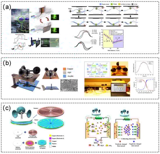
Figure 8.
Applications enabled by WD-TENG: (a) wind energy collection network based on TENGs (reproduced with permission [65]. Copyright 2019, Nano Energy). (b) Self-powered sensor system for detecting wind speed and direction (reproduced with permission [66]. Copyright 2018, ACS Nano). (c) Self-powered air purification system (reproduced with permission [73]. Copyright 2015, Nano Energy).
4. Summary and Perspective
Wind energy is one of the most common energy sources in nature, with unique attributes such as its green, safe and recyclable characteristics. TENG is an emerging renewable energy technology that can convert wind energy into electrical energy. In this review, we systematically summarized the latest developments in WD-TENG considering structural design, output performance and practical applications. Benefiting from their low cost, easy manufacture, and effective work at low frequencies, various wind energy-based devices have been designed. Some common structures are flutter-based structures, rotating structures and bionic structures. Moreover, WD-TENG can be combined with SC and EMG to broaden its application fields. On the one hand, WD-TENG can be used as a power source for portable devices or wearable devices. Not only that, WD-TENG allows for self-powered active sensors that can directly generate electrical signal as a response to applied wind energy. In brief, WD-TENG offers a completely new technology for wind energy harvesting. This review proposes and discusses some possible challenges and priority research directions (Figure 9), hoping to guide future research works. With the development of the Internet of things, the newly developed WD-TENG is expected to make progress in the following fields:
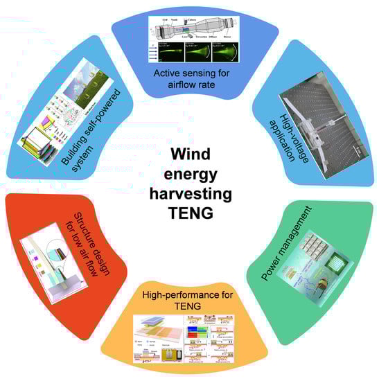
Figure 9.
Schematic diagram of various WD-TENG’s application fields (reproduced with permission [74]. Copyright 2020, Nano Energy); (reproduced with permission [75]. Copyright 2017, Nano Energy); (reproduced with permission [76]. Copyright 2020, Nature Communications); (reproduced with permission [77]. Copyright 2021, Joule); (reproduced with permission [78]. Copyright 2021, Nano Energy); (reproduced with permission [79]. Copyright 2017, Nano Energy).
- High-performance and integrated WD-TENG. A key factor that limits the practical application of TENG is output performance. For a single TENG, its output power is far from industrial applications. Many techniques are used to boost the output of TENG, such as optimizing its structure, developing new materials, reducing the thickness of the dielectric layer and mixing with other technologies (such as SCs and EMGs). However, as a potential substitute for traditional wind power technology, the integration of a large amount of TENG is necessary for large-scale energy collection and supply.
- Traditional large wind power generation struggles in relation to low-speed wind energy that is common in daily life, because the wind cannot reach the wind velocity threshold of current large wind turbines and has not been effectively utilized. At present, a series of WD-TENGs with various novel architectures and materials have been investigated, collection is rare in terms of low wind energy. In order to widen the minimum operating speed thresholds of WD-TENGs, the material and structure of the entire device need to be systematically optimized to acquire multiplied-frequency outputs.
- Energy storage. The output signal of a TENG changes with the ambient environment, which is time dependent, unstable and irregular. However, in practical applications, the power supply for electronics is a definite voltage and current. Therefore, the electricity generated by a TENG needs to be stored in a capacitor or battery first, and then used to power a device in a regulated manner. As such, energy storage is also one of the future research directions.
- Power management. From electricity generation to power storage, a power management circuit is required to maximize efficiency. Due to the high output voltage and low output current of a TENG, lowering the voltage without sacrificing total power needs to be investigated. Furthermore, the integration of TENG is subject to the size of a power management circuit.
- Self-powered sensing system. Introducing a WD-TENG into a self-powered sensing system cuts down the power consumption of the entire system, reduces the system’s complexity and, more importantly, implements a sustainable, independent and maintenance-free operation. Moreover, cooperating with other functional components and realizing self-powered operation for the entire system, including the supporting components, will largely broaden the sensing range and eventually enable the true application of TENGs as self-powered sensors in wireless sensor networks.
- Life span of WD-TENG. The practical application of a WD-TENG requires the device to have a long-term stable output and a long service life, which have long been challenges. Because TENG is based on the contact electrification of two materials, material abrasion is inevitable, except for in the case of the non-contact FS mode TENG. Designing advanced structures or selecting more durable material can extend a certain amount of service life for a WD-TENG. It is foreseeable that further progress in these areas will likely lead to the wide application of TENGs in various fields.
Author Contributions
J.L. and J.C. searched and summarized the related research articles on TENG. J.L. wrote the first draft manuscript. J.C. and H.G. revised the manuscript and supervised this review. All authors have read and agreed to the published version of the manuscript.
Funding
This research was funded by the National Natural Science Foundation of China (62004017, 61773254, 51572040, 51902035, 51772036), the Fundamental Research Funds for the Central Universities (2021CDJQY-019), the Dr. Scientific Research Fund of Chongqing normal university (Grant No. 21XLB006) and the Starting Research Fund of Chongqing University (0233001104468).
Institutional Review Board Statement
Not applicable.
Informed Consent Statement
Not applicable.
Acknowledgments
The research was supported by the National Natural Science Foundation of China (62004017, 61773254, 51572040, 51902035, 51772036), the Fundamental Research Funds for the Central Universities (2021CDJQY-019), the Scientific Research Fund of Chongqing normal university (Grant No. 21XLB006) and the Starting Research Fund of Chongqing University (0233001104468).
Conflicts of Interest
The authors declare no conflict of interest.
References
- Chen, B.; Yang, Y.; Wang, Z.L. Scavenging Wind Energy by Triboelectric Nanogenerators. Adv. Energy Mater. 2018, 8, 13. [Google Scholar] [CrossRef]
- Wu, Y.C.; Zhong, X.D.; Wang, X.; Yang, Y.; Wang, Z.L. Hybrid energy cell for simultaneously harvesting wind, solar, and chemical energies. Nano Res. 2014, 7, 1631–1639. [Google Scholar] [CrossRef]
- Falahi, M.; Lotfifard, S.; Ehsani, M.; Butler-Purry, K. Dynamic Model Predictive-Based Energy Management of DG Integrated Distribution Systems. IEEE Trans. Power Deliv. 2013, 28, 2217–2227. [Google Scholar] [CrossRef]
- Alnaser, S.W.; Ochoa, L.F. Advanced Network Management Systems: A Risk-Based AC OPF Approach. IEEE Trans. Power Syst. 2015, 30, 409–418. [Google Scholar] [CrossRef] [Green Version]
- Wang, C.; Bo, Y.U.; Xiao, J.; Guo, L. Sizing of Energy Storage Systems for Output Smoothing of Renewable Energy Systems. Proc. CSEE 2012, 32, 1–8. [Google Scholar]
- Shan, M.; Li, C.; Liang, T.; Mao, W. A Real-Time Optimal Control Strategy for Battery Energy Storage System to Smooth Active Output Fluctuation of Renewable Energy Sources. Power Syst. Technol. 2014, 38, 469–477. [Google Scholar]
- Fan, F.R.; Tian, Z.Q.; Wang, Z.L. Flexible triboelectric generator! Nano Energy 2012, 1, 328–334. [Google Scholar] [CrossRef]
- Zi, Y.L.; Niu, S.M.; Wang, J.; Wen, Z.; Tang, W.; Wang, Z.L. Standards and figure-of-merits for quantifying the performance of triboelectric nanogenerators. Nat. Commun. 2015, 6, 8. [Google Scholar] [CrossRef]
- Wang, Z.L.; Chen, J.; Lin, L. Progress in triboelectric nanogenerators as a new energy technology and self-powered sensors. Energy Environ. Sci. 2015, 8, 2250–2282. [Google Scholar] [CrossRef]
- Fan, K.; Liu, S.; Liu, H.; Zhu, Y.; Wang, W.; Zhang, D. Scavenging energy from ultra-low frequency mechanical excitations through a bi-directional hybrid energy harvester. Appl. Energy 2018, 216, 8–20. [Google Scholar] [CrossRef]
- Jeon, S.B.; Kim, D.; Yoon, G.W.; Yoon, J.B.; Choi, Y.K. Self-cleaning hybrid energy harvester to generate power from raindrop and sunlight. Nano Energy 2015, 12, 636–645. [Google Scholar] [CrossRef]
- Jung, S.; Lee, J.; Hyeon, T.; Lee, M.; Kim, D.H. Fabric-Based Integrated Energy Devices for Wearable Activity Monitors. Adv. Mater. 2014, 26, 6329–6334. [Google Scholar] [CrossRef]
- Yang, Y.; Zhang, H.L.; Lin, Z.H.; Zhou, Y.S.; Jing, Q.S.; Su, Y.J.; Yang, J.; Chen, J.; Hu, C.G.; Wang, Z.L. Human Skin Based Triboelectric Nanogenerators for Harvesting Biomechanical Energy and as Self-Powered Active Tactile Sensor System. ACS Nano 2013, 7, 9213–9222. [Google Scholar] [CrossRef] [Green Version]
- Bai, P.; Zhu, G.; Liu, Y.; Chen, J.; Jing, Q.S.; Yang, W.Q.; Ma, J.S.; Zhang, G.; Wang, Z.L. Cylindrical Rotating Triboelectric Nanogenerator. ACS Nano 2013, 7, 6361–6366. [Google Scholar] [CrossRef]
- Zhang, H.L.; Yang, Y.; Zhong, X.D.; Su, Y.J.; Zhou, Y.S.; Hu, C.G.; Wang, Z.L. Single-Electrode-Based Rotating Triboelectric Nanogenerator for Harvesting Energy from Tires. ACS Nano 2014, 8, 680–689. [Google Scholar] [CrossRef]
- Khan, F.I.; Hawboldt, K.; Iqbal, M.T. Life Cycle Analysis of wind–fuel cell integrated system. Renew. Energ. 2005, 30, 157–177. [Google Scholar] [CrossRef]
- Bae, J.; Lee, J.; Kim, S.; Ha, J.; Lee, B.S.; Park, Y.; Choong, C.; Kim, J.B.; Wang, Z.L.; Kim, H.Y.; et al. Flutter-driven triboelectrification for harvesting wind energy. Nat. Commun. 2014, 5, 4929. [Google Scholar] [CrossRef] [Green Version]
- Lin, Z.H.; Cheng, G.; Wu, W.; Pradel, K.C.; Wang, Z.L. Dual-Mode Triboelectric Nanogenerator for Harvesting Water Energy and as a Self-Powered Ethanol Nanosensor. ACS Nano 2014, 8, 6440–6448. [Google Scholar] [CrossRef]
- Zaw, N.Y.W.; Roh, H.; Kim, I.; Goh, T.S.; Kim, D. Omnidirectional Triboelectric Nanogenerator Operated by Weak Wind Towards a Self-Powered Anemoscope. Micromachines 2020, 11, 414. [Google Scholar]
- Gang, X.; Guo, Z.H.; Cong, Z.; Wang, J.; Chang, C.; Pan, C.; Pu, X.; Wang, Z.L. Textile Triboelectric Nanogenerators Simultaneously Harvesting Multiple "High-Entropy" Kinetic Energies. ACS Appl. Mater. Interfaces 2021, 13, 20145–20152. [Google Scholar] [CrossRef]
- Cheng, X.L.; Tang, W.; Song, Y.; Chen, H.T.; Zhang, H.X.; Wang, Z.L. Power management and effective energy storage of pulsed output from triboelectric nanogenerator. Nano Energy 2019, 61, 517–532. [Google Scholar] [CrossRef]
- Chen, Y.L.; Liu, D.; Wang, S.; Li, Y.F.; Zhang, X.S. Self-powered smart active RFID tag integrated with wearable hybrid nanogenerator. Nano Energy 2019, 64, 103911. [Google Scholar] [CrossRef]
- Yang, H.; Pang, Y.; Bu, T.; Liu, W.; Luo, J.; Jiang, D.; Zhang, C.; Wang, Z.L. Triboelectric micromotors actuated by ultralow frequency mechanical stimuli. Nat. Commun. 2019, 10, 2309. [Google Scholar] [CrossRef] [Green Version]
- Zheng, Q.; Zou, Y.; Zhang, Y.; Liu, Z.; Shi, B.; Wang, X.; Jin, Y.; Ouyang, H.; Li, Z.; Wang, Z.L. Biodegradable triboelectric nanogenerator as a life-time designed implantable power source. Sci. Adv. 2016, 2, 9. [Google Scholar] [CrossRef] [Green Version]
- Tang, W.; Jiang, T.; Fan, F.R.; Yu, A.F.; Zhang, C.; Cao, X.; Wang, Z.L. Liquid-Metal Electrode for High-Performance Triboelectric Nanogenerator at an Instantaneous Energy Conversion Efficiency of 70.6%. Adv. Funct. Mater. 2015, 25, 3718–3725. [Google Scholar] [CrossRef]
- Tang, Q.; Pu, X.J.; Zeng, Q.X.; Yang, H.M.; Li, J.; Wu, Y.; Guo, H.Y.; Huang, Z.Y.; Hu, C.G. A strategy to promote efficiency and durability for sliding energy harvesting by designing alternating magnetic stripe arrays in triboelectric nanogenerator. Nano Energy 2019, 66, 104087. [Google Scholar] [CrossRef]
- Tang, Q.; Guo, H.; Yan, P.; Hu, C. Recent progresses on paper-based triboelectric nanogenerator for portable self-powered sensing systems. EcoMat 2020, 2, e12060. [Google Scholar] [CrossRef]
- Qin, K.; Chen, C.; Pu, X.; Tang, Q.; He, W.; Liu, Y.; Zeng, Q.; Liu, G.; Guo, H.; Hu, C. Magnetic Array Assisted Triboelectric Nanogenerator Sensor for Real-Time Gesture Interaction. Nano-Micro. Lett. 2021, 13, 51. [Google Scholar] [CrossRef]
- Sun, J.; Zhang, L.; Li, Z.; Tang, Q.; Chen, J.; Huang, Y.; Hu, C.; Guo, H.; Peng, Y.; Wang, Z.L. A Mobile and Self-Powered Micro-Flow Pump Based on Triboelectricity Driven Electroosmosis. Adv. Mater. 2021, 33, 8. [Google Scholar] [CrossRef] [PubMed]
- Wang, Z.L.; Jiang, T.; Xu, L. Toward the blue energy dream by triboelectric nanogenerator networks. Nano Energy 2017, 39, 9–23. [Google Scholar] [CrossRef]
- Wang, Z.L. On Maxwell’s displacement current for energy and sensors: The origin of nanogenerators. Mater. Today 2017, 20, 74–82. [Google Scholar] [CrossRef]
- Wu, C.S.; Wang, A.C.; Ding, W.B.; Guo, H.Y.; Wang, Z.L. Triboelectric Nanogenerator: A Foundation of the Energy for the New Era. Adv. Energy Mater. 2019, 9, 1802906. [Google Scholar] [CrossRef]
- Zhang, C.; Tang, W.; Han, C.; Fan, F.; Wang, Z.L. Theoretical comparison, equivalent transformation, and conjunction operations of electromagnetic induction generator and triboelectric nanogenerator for harvesting mechanical energy. Adv. Mater. 2014, 26, 3580–3591. [Google Scholar] [CrossRef] [PubMed]
- Zi, Y.L.; Guo, H.Y.; Wen, Z.; Yeh, M.H.; Hu, C.G.; Wang, Z.L. Harvesting Low-Frequency (<5 Hz) Irregular Mechanical Energy: A Possible Killer Application of Triboelectric Nanogenerator. ACS Nano 2016, 10, 4797–4805. [Google Scholar] [CrossRef]
- Xue, Y.; Tai, N. Review of contribution to frequency control through variable speed wind turbine. Renew. Energ. 2011, 36, 1671–1677. [Google Scholar]
- Qu, R.; Liu, Y.; Jin, W. Review of Superconducting Generator Topologies for Direct-Drive Wind Turbines. IEEE Trans. Appl. Supercond. 2013, 23, 8. [Google Scholar]
- Zhang, Y.; Zeng, Q.X.; Wu, Y.; Wu, J.; Yuan, S.L.; Tan, D.J.; Hu, C.G.; Wang, X. An Ultra-Durable Windmill-Like Hybrid Nanogenerator for Steady and Efficient Harvesting of Low-Speed Wind Energy. Nano-Micro. Lett. 2020, 12, 11. [Google Scholar] [CrossRef]
- Dudem, B.; Huynh, N.D.; Kim, W.; Kim, D.H.; Hwang, H.J.; Choi, D.; Yu, J.S. Nanopillar-array architectured PDMS-based triboelectric nanogenerator integrated with a windmill model for effective wind energy harvesting. Nano Energy 2017, 42, 269–281. [Google Scholar] [CrossRef]
- Huynh, N.D.; Lin, Z.H.; Choi, D. Dynamic balanced hybridization of TENG and EMG via Tesla turbine for effectively harvesting broadband mechanical pressure. Nano Energy 2021, 85, 12. [Google Scholar] [CrossRef]
- Du, X.Y.; Li, N.W.; Liu, Y.B.; Wang, J.N.; Yuan, Z.Q.; Yin, Y.Y.; Cao, R.; Zhao, S.Y.; Wang, B.; Wang, Z.L.; et al. Ultra-robust triboelectric nanogenerator for harvesting rotary mechanical energy. Nano Res. 2018, 11, 2862–2871. [Google Scholar] [CrossRef]
- Xie, Y.N.; Wang, S.H.; Lin, L.; Jing, Q.S.; Lin, Z.H.; Niu, S.M.; Wu, Z.Y.; Wang, Z.L. Rotary Triboelectric Nanogenerator Based on a Hybridized Mechanism for Harvesting Wind Energy. ACS Nano 2013, 7, 7119–7125. [Google Scholar] [CrossRef]
- Li, S.M.; Wang, S.H.; Zi, Y.L.; Wen, Z.; Lin, L.; Zhang, G.; Wang, Z.L. Largely Improving the Robustness and Lifetime of Triboelectric Nanogenerators through Automatic Transition between Contact and Noncontact Working States. ACS Nano 2015, 9, 7479–7487. [Google Scholar] [CrossRef]
- Ren, X.H.; Fan, H.Q.; Wang, C.; Ma, J.W.; Li, H.; Zhang, M.C.; Lei, S.H.; Wang, W.J. Wind energy harvester based on coaxial rotatory freestanding triboelectric nanogenerators for self-powered water splitting. Nano Energy 2018, 50, 562–570. [Google Scholar] [CrossRef]
- Moon, H.; Chung, J.; Kim, B.; Yong, H.; Kim, T.; Lee, S.; Lee, S. Stack/flutter-driven self-retracting triboelectric nanogenerator for portable electronics. Nano Energy 2017, 31, 525–532. [Google Scholar] [CrossRef]
- Zhang, Y.; Fu, S.C.; Chan, K.C.; Shin, D.M.; Chao, C.Y.H. Boosting power output of flutter-driven triboelectric nanogenerator by flexible flagpole. Nano Energy 2021, 88, 12. [Google Scholar] [CrossRef]
- Wang, J.L.; Gu, S.H.; Zhang, C.Y.; Hu, G.B.; Chen, G.; Yang, K.; Li, H.; Lai, Y.Y.; Litak, G.; Yurchenko, D. Hybrid wind energy scavenging by coupling vortex-induced vibrations and galloping. Energy Conv. Manag. 2020, 213, 11. [Google Scholar] [CrossRef]
- Wang, Q.; Zou, H.X.; Zhao, L.C.; Li, M.; Wei, K.X.; Huang, L.P.; Zhang, W.M. A synergetic hybrid mechanism of piezoelectric and triboelectric for galloping wind energy harvesting. Appl. Phys. Lett. 2020, 117, 5. [Google Scholar] [CrossRef]
- Li, R.; Zhang, H.; Wang, L.; Liu, G.H. A Contact-Mode Triboelectric Nanogenerator for Energy Harvesting from Marine Pipe Vibrations. Sensors 2021, 21, 21. [Google Scholar]
- Zhang, L.; Zhang, B.; Chen, J.; Jin, L.; Deng, W.; Tang, J.; Zhang, H.; Pan, H.; Zhu, M.; Yang, W. Lawn Structured Triboelectric Nanogenerators for Scavenging Sweeping Wind Energy on Rooftops. Adv. Mater. 2016, 28, 1650–1656. [Google Scholar] [CrossRef]
- Zhao, Z.F.; Pu, X.; Du, C.H.; Li, L.X.; Jiang, C.Y.; Hu, W.G.; Wang, Z.L. Freestanding Flag-Type Triboelectric Nanogenerator for Harvesting High-Altitude Wind Energy from Arbitrary Directions. ACS Nano 2016, 10, 1780–1787. [Google Scholar] [CrossRef] [PubMed]
- Yang, Y.; Zhu, G.; Zhang, H.; Chen, J.; Zhong, X.; Lin, Z.H.; Su, Y.; Bai, P.; Wen, X.; Wang, Z.L. Triboelectric nanogenerator for harvesting wind energy and as self-powered wind vector sensor system. ACS Nano 2013, 7, 9461–9468. [Google Scholar] [CrossRef] [PubMed]
- Ravichandran, A.N.; Calmes, C.; Serres, J.R.; Ramuz, M.; Blayac, S. Compact and high performance wind actuated venturi triboelectric energy harvester. Nano Energy 2019, 62, 449–457. [Google Scholar] [CrossRef]
- Chaudhari, C.D.; Waghmare, S.A.; Kotwal, A. Numerical Analysis of Venturi Ducted Horizontal Axis Wind Turbine for Efficient Power Generation. Int. J. Mech. Eng. Comput. Appl. 2013, 1, 90–93. [Google Scholar]
- Lin, H.B.; He, M.H.; Jing, Q.S.; Yang, W.F.; Wang, S.T.; Liu, Y.; Zhang, Y.L.; Li, J.; Li, N.; Ma, Y.W.; et al. Angle-shaped triboelectric nanogenerator for harvesting environmental wind energy. Nano Energy 2019, 56, 269–276. [Google Scholar] [CrossRef]
- Kim, D.; Tcho, I.W.; Choi, Y.K. Triboelectric nanogenerator based on rolling motion of beads for harvesting wind energy as active wind speed sensor. Nano Energy 2018, 52, 256–263. [Google Scholar] [CrossRef]
- Lin, Z.; Zhang, B.; Guo, H.; Wu, Z.; Wang, Z.L. Super-robust and frequency-multiplied triboelectric nanogenerator for efficient harvesting water and wind energy. Nano Energy 2019, 64, 7. [Google Scholar] [CrossRef]
- Ahmed, A.; Hassan, I.; Song, P.; Gamaleldin, M.; Radhi, A.; Panwar, N.; Tjin, S.C.; Desoky, A.Y.; Sinton, D.; Yong, K.T. Self-adaptive Bioinspired Hummingbird-wing Stimulated Triboelectric Nanogenerators. Sci. Rep. 2017, 7, 17143. [Google Scholar] [CrossRef] [Green Version]
- Zhao, Z.; Zhang, Z.; Xu, L.; Gao, F.; Zhang, Y. Tumbler-shaped hybrid triboelectric nanogenerators for amphibious self-powered environmental monitoring. Nano Energy 2020, 76, 104960. [Google Scholar] [CrossRef]
- Wang, X.; Wang, S.H.; Yang, Y.; Wang, Z.L. Hybridized Electromagnetic—Triboelectric Nanogenerator for Scavenging Air-Flow Energy to Sustainably Power Temperature Sensors. ACS Nano 2015, 9, 4553–4562. [Google Scholar] [CrossRef]
- Fan, X.; He, J.; Mu, J.; Qian, J.; Chou, X. Triboelectric-Electromagnetic Hybrid Nanogenerator Driven by Wind for Self-powered Wireless Transmission in Internet of Things and Self-Powered Wind Speed Sensor. Nano Energy 2019, 68, 104319. [Google Scholar] [CrossRef]
- Ye, C.Y.; Dong, K.; An, J.; Yi, J.; Peng, X.; Ning, C.; Wang, Z.L. A Triboelectric-Electromagnetic Hybrid Nanogenerator with Broadband Working Range for Wind Energy Harvesting and a Self-Powered Wind Speed Sensor. ACS Energy Lett. 2021, 6, 1443–1452. [Google Scholar] [CrossRef]
- Roh, H.; Kim, I.; Kim, D. Ultrathin unified harvesting module capable of generating electrical energy during rainy, windy, and sunny conditions. Nano Energy 2020, 70, 104515. [Google Scholar] [CrossRef]
- Chen, J.; Huang, Y.; Zhang, N.; Zou, H.; Liu, R.; Tao, C.; Fan, X.; Wang, Z.L. Micro-cable structured textile for simultaneously harvesting solar and mechanical energy. Nat. Energy 2016, 1, 16138. [Google Scholar] [CrossRef]
- Qian, J.G.; Jing, X.J. Wind-driven hybridized triboelectric-electromagnetic nanogenerator and solar cell as a sustainable power unit for self-powered natural disaster monitoring sensor networks. Nano Energy 2018, 52, 78–87. [Google Scholar] [CrossRef]
- Kim, H.; Zhou, Q.; Kim, D.; Oh, I.K. Flow-induced Snap-through Triboelectric Nanogenerator. Nano Energy 2019, 68, 104379. [Google Scholar] [CrossRef]
- Wang, J.Y.; Ding, W.B.; Pan, L.; Wu, C.S.; Yu, H.; Yang, L.J.; Liao, R.J.; Wang, Z.L. Self-Powered Wind Sensor System for Detecting Wind Speed and Direction Based on a Triboelectric Nanogenerator. ACS Nano 2018, 12, 3954–3963. [Google Scholar] [CrossRef]
- Wang, P.H.; Pan, L.; Wang, J.Y.; Xu, M.Y.; Dai, G.Z.; Zou, H.Y.; Dong, K.; Wang, Z.L. An Ultra-Low-Friction Triboelectric-Electromagnetic Hybrid Nanogenerator for Rotation Energy Harvesting and Self-Powered Wind Speed Sensor. ACS Nano 2018, 12, 9433–9440. [Google Scholar] [CrossRef]
- Zhao, T.; Cao, S.; Yang, S.; Guo, R.; Zhang, H. A self-powered counter/timer based on a clock pointer-like frequency-tunable triboelectric nanogenerator for wind speed detecting. Nano Energy 2019, 65, 104025. [Google Scholar] [CrossRef]
- Xiong, J.Q.; Luo, H.S.; Gao, D.C.; Zhou, X.R.; Cui, P.; Thangavel, G.; Parida, K.; Lee, P.S. Self-restoring, waterproof, tunable microstructural shape memory triboelectric nanogenerator for self-powered water temperature sensor. Nano Energy 2019, 61, 584–593. [Google Scholar] [CrossRef]
- Wu, Y.; Su, Y.J.; Bai, J.J.; Zhu, G.; Zhang, X.Y.; Li, Z.L.; Xiang, Y.; Shi, J.L. A Self-Powered Triboelectric Nanosensor for PH Detection. J. Nanomater. 2016, 2016, 6. [Google Scholar] [CrossRef]
- Lin, Z.H.; Zhu, G.; Zhou, Y.S.; Yang, Y.; Bai, P.; Chen, J.; Wang, Z.L. A Self-Powered Triboelectric Nanosensor for Mercury Ion Detection. Angew. Chem.-Int. Edit. 2013, 52, 5065–5069. [Google Scholar] [CrossRef] [PubMed]
- Kim, W.; Choi, D.; Kwon, J.Y.; Choi, D. A self-powered triboelectric microfluidic system for liquid sensing. J. Mater. Chem. A 2018, 6, 14069–14076. [Google Scholar] [CrossRef]
- Chen, S.W.; Gao, C.Z.; Tang, W.; Zhu, H.R.; Han, Y.; Jiang, Q.W.; Li, T.; Cao, X.; Wang, Z.L. Self-powered cleaning of air pollution by wind driven triboelectric nanogenerator. Nano Energy 2015, 14, 217–225. [Google Scholar] [CrossRef]
- Zhang, L.B.; Meng, B.; Xia, Y.; Deng, Z.M.; Dai, H.L.; Hagedorn, P.; Peng, Z.C.; Wang, L. Galloping triboelectric nanogenerator for energy harvesting under low wind speed. Nano Energy 2020, 70, 11. [Google Scholar] [CrossRef]
- Ahmed, A.; Hassan, I.; Hedaya, M.; El-Yazid, T.A.; Zu, J.; Wang, Z.L. Farms of triboelectric nanogenerators for harvesting wind energy: A potential approach towards green energy. Nano Energy 2017, 36, 21–29. [Google Scholar] [CrossRef]
- He, W.C.; Liu, W.L.; Chen, J.; Wang, Z.; Liu, Y.K.; Pu, X.J.; Yang, H.M.; Tang, Q.; Yang, H.K.; Guo, H.Y.; et al. Boosting output performance of sliding mode triboelectric nanogenerator by charge space-accumulation effect. Nat. Commun. 2020, 11, 8. [Google Scholar]
- Wang, Z.; Liu, W.L.; He, W.C.; Guo, H.Y.; Long, L.; Xi, Y.; Wang, X.; Liu, A.P.; Hu, C.G. Ultrahigh Electricity Generation from Low-Frequency Mechanical Energy by Efficient Energy Management. Joule 2021, 5, 441–455. [Google Scholar] [CrossRef]
- Wang, Y.; Yang, E.; Chen, T.Y.; Wang, J.Y.; Hu, Z.Y.; Mi, J.C.; Pan, X.X.; Xu, M.Y. A novel humidity resisting and wind direction adapting flag-type triboelectric nanogenerator for wind energy harvesting and speed sensing. Nano Energy 2020, 78, 9. [Google Scholar] [CrossRef]
- Chen, B.; Yang, N.N.; Jiang, Q.; Chen, W.S.; Yang, Y. Transparent triboelectric nanogenerator-induced high voltage pulsed electric field for a self-powered handheld printer. Nano Energy 2018, 44, 468–475. [Google Scholar] [CrossRef]


Publisher’s Note: MDPI stays neutral with regard to jurisdictional claims in published maps and institutional affiliations. |
© 2021 by the authors. Licensee MDPI, Basel, Switzerland. This article is an open access article distributed under the terms and conditions of the Creative Commons Attribution (CC BY) license (https://creativecommons.org/licenses/by/4.0/).