Article

Analysis of Bearing Characteristics of Energy Pile Group Based on Exponential Model

1
Faculty of Engineering, Zhejiang Institute, China University of Geosciences, Wuhan 430074, China
2
Research Center of Coastal Urban Geotechnical Engineering, Zhejiang University, Hangzhou 310058, China
*
Authors to whom correspondence should be addressed.
Energies 2021, 14(21), 6881; https://doi.org/10.3390/en14216881
Submission received: 4 September 2021 / Revised: 4 October 2021 / Accepted: 11 October 2021 / Published: 20 October 2021

Abstract

:
Energy piles are an emerging energy technology for both structural and thermal purposes. To support structure load, piles are always used in groups with raft; however, the cost and complexity of field tests and numerical modelling limits the research on the bearing characteristics of energy pile group. In this paper, exponential model was applied to simulate the thermo-mechanical soil-pile interaction of energy pile group. Axial load transfer (τ-z) analysis was first performed to calculate the shear stress distribution in the soil, then matrix displacement method was introduced to determine the thermo-mechanical response of energy pile group. The validity of the analytical model was tested against field tests and numerical results. A case study was further performed to analyze the influence of thermal cycles and arrangement of thermally active piles on the bearing response of the whole pile group. Test results show that with the thermally activated pile in pile group, (1) differential settlement increases with thermal cycle numbers; (2) the axial force of thermally active pile increases during heating process and decreases during cooling process, and this trend varies for the surrounding nonthermal piles; (3) induced load on thermal pile increases with thermal cycles, but decreases for nonthermal piles. The proposed analytical model is expected to serve as a simple and convenient alternative for the preliminary analysis on the bearing characteristics of energy group pile.

1. Introduction

Energy pile is a novel and environmentally friendly foundation type that achieves the dual role of supporting superstructure and transferring heat between structure and ground. Due to increasing global demand for clean and green energy, research on the thermomechanical behavior of energy piles is gaining increasing popularity [1,2]. Most of the work focuses on the thermal performance and optimal layout of energy pile, while research on its function as structure support has been less reported [3]. Actually, energy piles are under the coupling influence of mechanical and thermal loads. It has been widely reported that the continuous cooling and heating process would impose extra stresses and strains on the pile structure and surrounding soil, thus undermining the long-term safety of the structure [4]. A better understanding of the influence of thermal cycles on the mechanical behavior of energy pile will promote the development and optimization of design guidelines for this new foundation type. For most civil structures, the foundation type always involves groups of piles connected by a raft, rather than a single pile. The thermomechanical behavior of energy pile group is very complex due to the interaction effect between energy piles, nonthermal piles, pile raft and surrounding soil, which adds experimental cost and modelling difficulty to the study of the pile group system [5,6].
Experimental studies, especially field full-scale tests, are by far the most reliable and direct way to observe and analyze the thermomechanical behavior of energy pile groups. Based on field experiments, Mimouni and Laloui [7] revealed that heating the entire pile group could reduce the differential displacements compared to the energy pile group with non-active piles. Peng et al. [8] conducted thermal cycle tests on the floating model energy pile group and single energy pile. The thermomechanical response, including axial pile stress and pile displacement, was quite different between the single energy pile and the pile group. This was explained by the “group effect”, which weakened the lateral confining pressure in the pile group. Fang et al. [9] performed field tests on a 2 × 2 pile-raft foundation. Three thermal loading schemes were performed to consider the influence of location arrangement and number of energy piles on the thermomechanical behavior of the pile-raft system. Test results indicated that the heating process would induce thermal expansion for both the energy pile and its surrounding non-active pile, and this influence differed for adjacent piles and diagonal pile. Also, the nonuniform thermal loading scheme would induce differential settlement of the pile raft foundation and the differential settlement was less obvious with increasing active piles in the pile group.
Due to the expensive and time-consuming experimental setup, valid test data are relatively scarce, and numerical modelling provides a convenient and promising alternative to investigate the soil-pile interaction under thermal and mechanical load [10]. Jeong et al. [11] conducted numerical parametrical analysis on the design parameters of energy pile group, including pile spacing, pile location, soil type, and bearing condition. The pile cap seemed to limit the vertical pile displacement during the cooling process. Based on three-dimensional thermomechanical numerical model, Salciarini et al. [12] revealed that the maximum axial load difference occurred at around one month after thermal cycles. Di Donna and Laloui [13] adopted a fully coupled thermo-hydro-mechanical Lagrangian-updated formulation to simulate the thermomechanical behavior of single energy pile and pile group. Though the thermal-induced stress and strain were in the acceptable range, it was recommended to consider the influence of thermal cycles in the design of energy piles. Saggu and Chakraborty [14] analyzed the influence of pile spacing and arrangement of active piles on the thermomechanical response of energy pile group. The cyclic thermal load would induce higher axial displacement and stress compared to the condition with only mechanical load. For numerical case with pile spacing of 2.5 m, a 47% increase in displacement was observed for thermal piles compared to piles under mechanical load only and a recommendation of at least 4 m spacing was finally provided.
The above research provides valuable information about the thermal influence on the mechanical behavior of energy pile group. However, numerical techniques still have shortcomings in simulating complex and intricate models. As a result, a more convenient and simplified approach is necessary to facilitate the practical application. Knellwolf et al. [15] proposed a calculation method of the temperature effect on the energy pile behavior. One-dimensional finite difference model was built to consider the variation of soil properties at different layers. The load-transfer curve proposed by Frank and Zhao [16] was used to simulate the pile-soil interaction, and the thermal loading behavior was determined by the selection of null point. Validity of the proposed method was tested against field test data. Further analysis indicated that the heating process would produce extra compression of the pile, which in turn mobilized more shear stress, while the cooling process led to decreased shear stress and the development of tensile stress in the pile. Chen and McCartney [17] extended the traditional load transfer (τ-z) method by incorporating the thermo-elastic deformation of the foundation the null point criterion. The thermomechanical τ-z method was used to evaluate the influence of different representative boundary conditions and achieved good results. To avoid the selection of null point under the influence of mechanical load and temperature, Fei et al. [18] applied a modified hyperbolic function to simulate the pile-soil interaction and the thermal effect was characterized by thermal load. Though satisfactory results were achieved, the hyperbolic model would produce hysteresis loop during the loading-unloading process; as a result, a reduction factor was needed to simulate the progressive softening behavior of soil shear strain. The above models lay a solid foundation for the analytical analysis of energy group pile. However, further modifications are still necessary to construct models that simplify the selection of input parameter while reflecting the progressive evolvement of soil property.
The objective of this paper is to provide a simple and convenient analytical approach to evaluate the thermal effect on the bearing characteristics of energy group pile. Exponential model is introduced to simulate the nonlinear behavior at the pile-soil interface, and the thermomechanical behavior is simplified as mechanical and thermal load. The validity of the analytical model is checked against reported pile group data. On this basis, the influence of thermal cycle numbers and the arrangement of thermally active piles on the bearing performance, in terms of axial force and settlement, of the energy pile group is evaluated.

2. Governing Equations for Pile Group Settlement

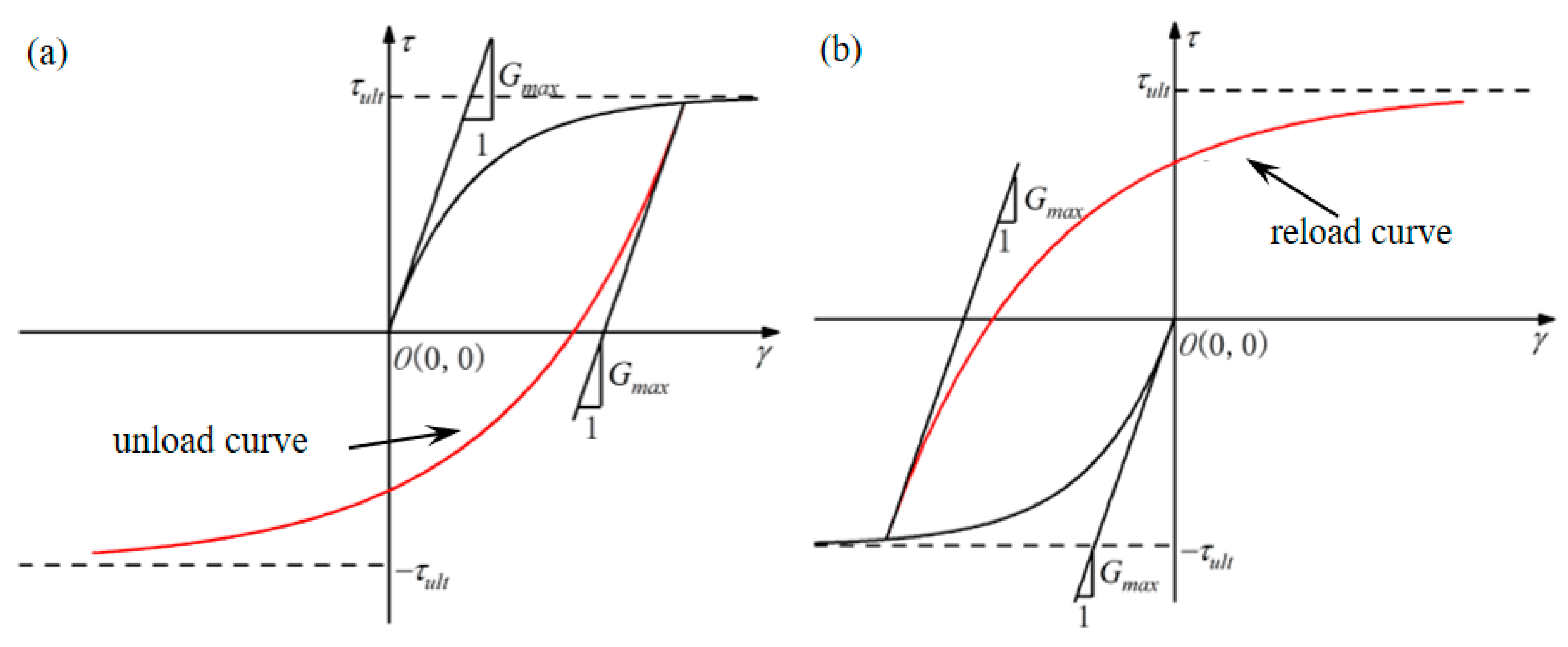
2.1. Pile Shaft Response

Settlement calculation for pile group is more complex compared to that for single pile due to the interaction of pile-soil-pile-raft. To simplify the calculation, settlement of pile group is always divided into two parts, settlement of single pile and induced settlement caused by group effect.
Under vertical load, a certain range of soil around the pile would enter the plastic stage, while soil outside this range is still in an elastic state. It is acknowledged that the nonlinear load-settlement response of single pile depends on the relative displacement at the pile-soil interface. As a result, the pile displacement u at certain depth is decomposed into the relative displacement s at the pile-soil interface and the displacement of the surrounding soil w, as
u = s + w
The shear stress and relative displacement at pile shaft are calculated based on the exponential load transfer model [19,20], as
γ 0 , τ = a ( 1 e b γ ) γ < 0 , τ = a ( 1 e b γ )
where τ is the shear stress at the pile shaft, γ is the relative displacement at the pile-soil interface, a and b are model parameters, which are defined as
a = τ u l t
b = G max τ u l t
where τult is the ultimate shear stress at the pile-soil interface, Gmax is the initial shear stiffness at the pile-soil interface.
The elastic displacement of the surrounding soil w is calculated according to Randolph and Wroth [21] as
w = r G ln ( r m r ) τ
where r is the pile radius, rm is the influence radius around the pile, G is the shear modulus of the soil.
Combining Equations (1), (2) and (5) produces the relationship between incremental displacement and shear stress as
δ u = [ 1 b ( a τ ) + r G ln ( r m r ) τ ] δ τ
Equation (6) is normally used for monotonic loading. As for energy piles under thermal loading, heating and cooling cycles would lead to the continuous loading and reloading behavior of the pile-soil system. To simulate the cyclic behavior, a load transfer model considering cyclic load effect is constructed according to Masing criterion [18].
At unloading stage,
τ = τ 0 a 1 ( 1 e b 1 ( γ γ 0 ) )
At reloading stage,
τ = τ 0 + a 1 ( 1 e b 1 ( γ γ 0 ) )
where τ0 and γ0 are the shear stress and relative displacement at the transition point between loading and unloading stage, a 1 , b 1 and a 1 , b 1 are model parameters, which are defined as
a 1 = τ u l t + τ 0
b 1 = G max a 1 = G max τ u l t + τ 0
a 1 = τ u l t τ 0
b 1 = G max a 1 = G max τ u l t τ 0
By differentiating Equations (7) and (8), the relationship between incremental displacement and shear stress under cyclic loading, as shown in Figure 1, is described mathematically as:
δ u = C δ τ
At loading stage,
C = 1 b 1 ( τ τ 0 + a 1 ) + r G ln ( r m r )
At reloading stage,
C = 1 b 1 ( a 1 τ + τ 0 ) + r G ln ( r m r )

2.2. Pile Base Response

The bearing stress and relative displacement at pile base are calculated based on the exponential load transfer model as
p = a 2 ( 1 e b 2 γ b )
where p is the base resistance and γ b is the relative displacement at the pile base, a 2 and b 2 are model parameters, which are defined as
a 2 = τ u l t
b 2 = G max τ u l t
where τ ult is the ultimate shear stress at the pile base; G max is the initial shear stiffness at the pile base.
And the relationship between incremental displacement and shear stress under cyclic loading is
δ u = C b δ τ
At unloading stage,
C b = 1 b 2 ( τ τ 0 + a 2 )
At reloading stage,
C b = 1 b 2 ( a 2 τ + τ 0 )

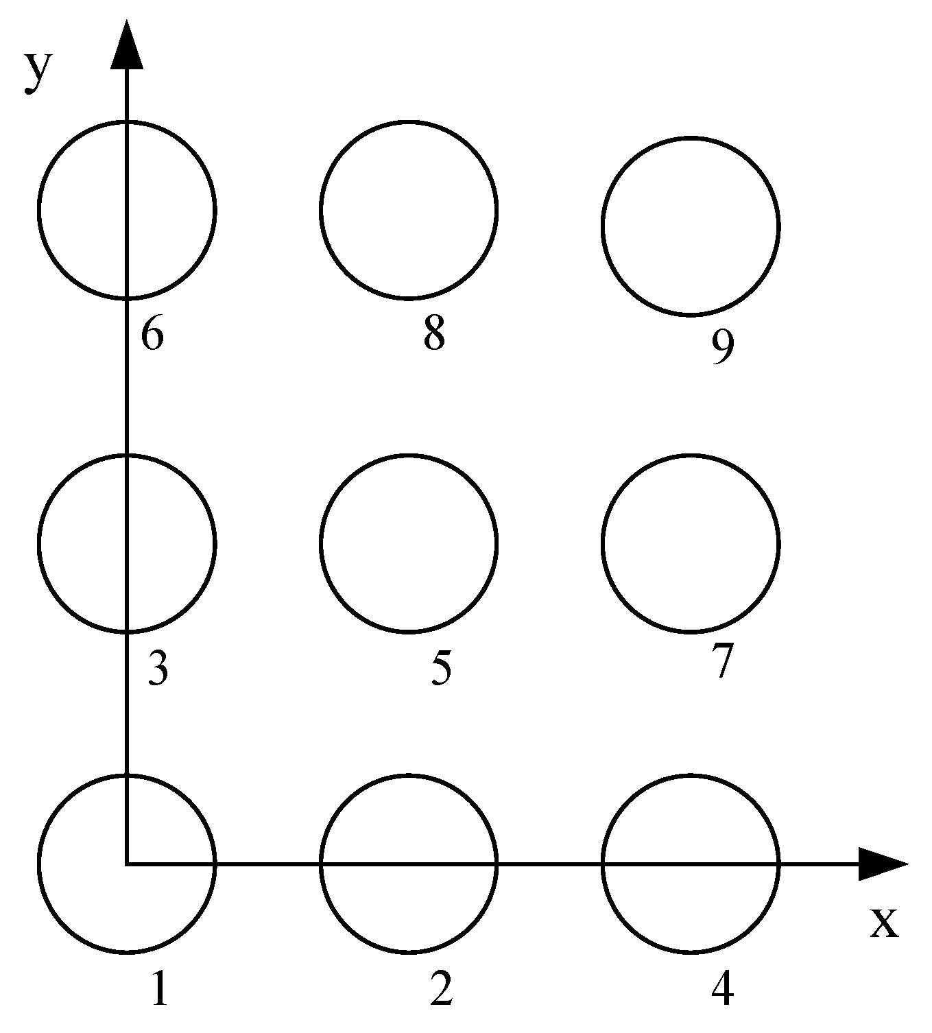
2.3. Pile-Pile Interaction

For pile i in a pile group, the relative displacement at the pile shaft could be decomposed into the nonlinear displacement induced by the shear stress at the pile shaft and the induced elastic displacement caused by the m piles in the influence range around pile i, as
δ u i z = δ u i i z + j = 1 m δ u i j z
where δ u i i z is the displacement caused by the shear stress at pile i, which could be calculated by Equation (19).
According to Lee and Xiao [22], δ u i i z can be determined as
δ u i j z = r G ln ( r m S i j ) δ τ j z
where S i j is the distance between pile i and pile j; when S i j > r m , the influence of surrounding pile could be ignored.
The coefficient r m is influenced by the pile length and soil layer, and its value tends to increase with depth, which could be calculated as
r m = 2 δ ( 1 μ s ) L
where δ is the soil shear modulus, μ s is poisson ratio, L is pile length.
In pile group, assuming the total pile number is n, then the displacement of single pile i is
δ u i z = j = 1 n C i j δ τ j
C i j = C i = j C i j = r G ln ( r m S i j ) i j
According to Randolph and Wroth [21], the displacement increment at the pile base caused by pile interaction could be seemed as elastic. On this basis, the base displacement increment of pile i in a pile group could be calculated as
δ w b i = j = 1 n C b i j δ P j
C i j = C b i = j C i j = ( 1 μ s ) 2 π G b S i j i j

3. Solution of the Analytical Model

In general, the energy pile is first subjected to the load of superstructure. When the structure needs to be cooled or heated, the energy pile is then put into operation and begins to suffer the cyclic heating and cooling process [23]. On this basis, the thermomechanical process is simplified as mechanical loading and thermal loading.

3.1. Governing Equation for Single Pile

According to the equilibrium state of pile element, the following equation is obtained
N z + 2 π r τ = 0
where N is the pile axial force, z is depth.
Considering the thermal effect, the axial strain of the pile can be calculated as
ε = u z = N E p A a T Δ T
where ε is axial strain, E p is Young’s modulus of the pile, A is the cross-section area of the pile, a T is the thermal expansion coefficient of the pile, and Δ T is the temperature variation.
By differentiating Equation (30) and combining Equation (29), one obtains
τ = E p A 2 π r 2 u z 2
In Equation (31), the basic assumption is that the temperature increment keeps the same along the pile length. The pile response under mechanical loading is first solved, the solution then serves as the initial condition at thermal loading stage.

3.2. Solution of Governing Equation under Mechanical Load

For a single pile with length of L, it is discretized into N sections, with each section a length of Δh and a total of M = N + 1 nodes. By combing Equations (25) and (31), the solution based on 2nd order difference formula is
δ u i , l = j = 1 n E p A 2 π r δ u j , l + 1 2 δ u j , l + δ u j , l 1 Δ h 2
j = 1 n C i j , l a δ u j , l 1 + ( 2 a C i i , l + 1 ) δ u i , l + j = 1 , i j n 2 a C i j , l δ u j , l j = 1 n C i j , l a δ u j , l + 1 = 0
where a = E p A 2 π r Δ h 2 .
To meet the solution accuracy for the pile top and bottom nodes, two fictitious nodes are added at position 0 and M + 1, and the formula could be solved considering the boundary condition.
Due to the raft constraint at pile head, the displacement values at pile top could be assumed as equal as long as the pile raft is stiff enough, and the external load could be assumed as the sum of the load on each pile. According to this assumption, the following equations are obtained
δ u 1 , 1 = δ u 2 , 1 = = δ u n , 1
δ N 1 , 1 + δ N 2 , 1 + + δ N n , 1 = δ P
Combining the above equations with Equation (30), Equation (35) could be present in the form of Equation (36) based on the 1st order difference formula, that is
j = 1 n β ( δ u j , 0 δ u j , 2 ) = δ P
where β = E p A / 2 Δ h .
Similarly, the iterative relationship of node M at pile base is derived as
j = 1 n C b i j β δ u j , M 1 δ u i , M j = 1 n C b i j β δ u j , M + 1 = 0
Combining Equations (33), (34), (36) and (37) in a matrix form, the governing equation for pile group is obtained as
[ [ K 1 , 1 ] [ K 1 , 2 ] [ K 1 , n ] [ K 2 , 1 ] [ K 2 , 2 ] [ K 2 , n ] [ K n , 1 ] [ K n , 2 ] [ K n , n ] ] { { δ u 1 } { δ u 2 } { δ u n } } = { { δ F 1 } { δ F 2 } { δ F n } }
The stiffness matrix [Ki,j] is a M + 2 order square matrix, and the non-zero elements are
K i , j ( l , l 1 ) = a C i j , l K i , j ( l , l ) = { 2 a C i j , l + 1 , i = j 2 a C i j , l , i j K i , j ( l , l 1 ) = a C i j , l }
where l = 2…M + 1.
Elements at the first and M + 2 rows are fictitious nodes, which can be determined as
K i , j ( 1 , 2 ) = { 1 , j = i 1 , j = i + 1 K n , j ( 1 , 1 ) = β K n , j ( 1 , 3 ) = β K i , j ( M + 2 , M ) = C b i j β K i , j ( M + 2 , M + 1 ) = { 1 , j = i 0 , j i K i , j ( M + 2 , M + 2 ) = C b i j β }

3.3. Solution of Governing Equation under Thermal Load
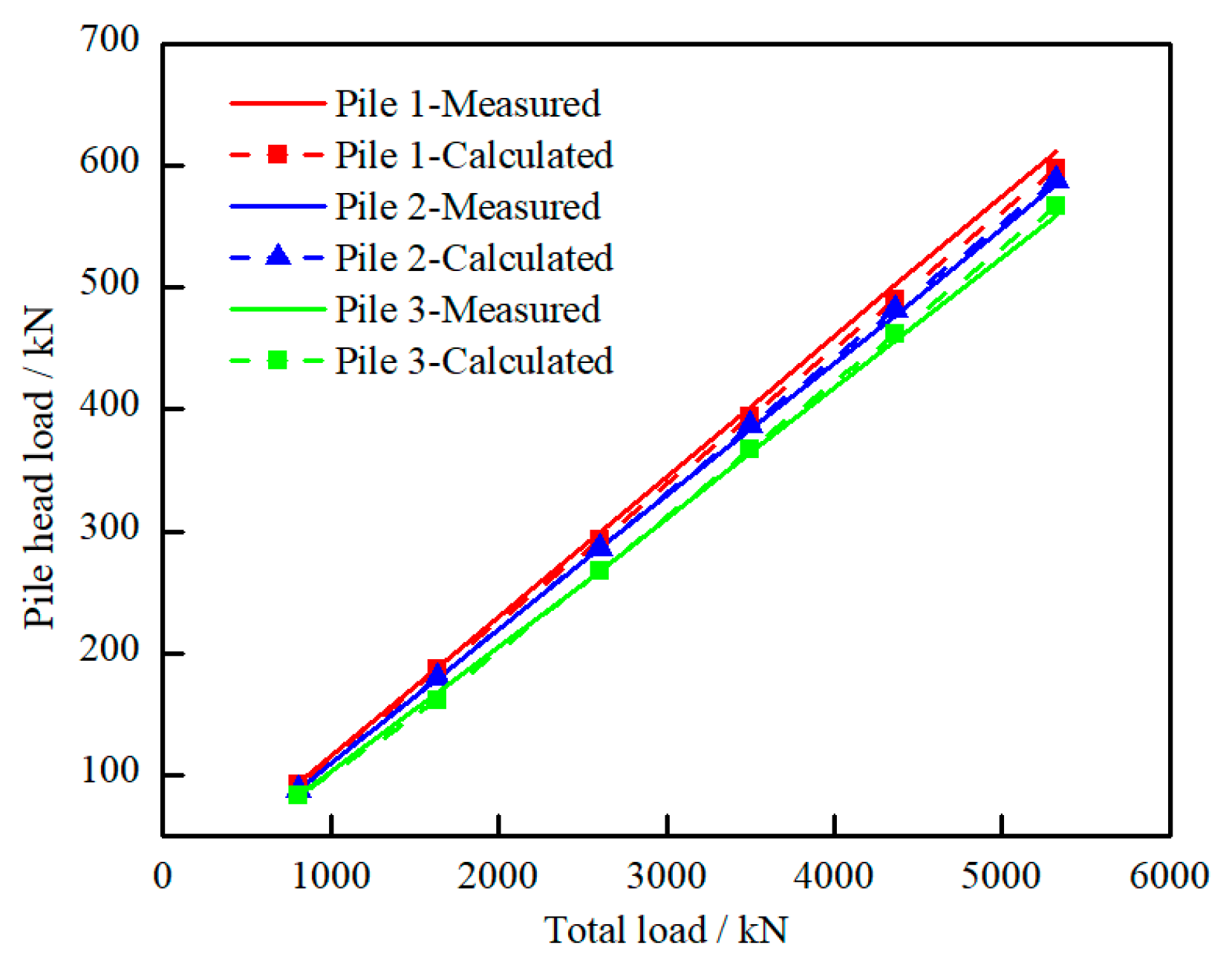
For thermal loading simulation, the solution under mechanical load is used as the initial condition, and the governing equation keeps the same form. For energy pile group with thermally-active piles and nonactive piles, piles at different locations would experience different load condition, which would lead to different pile response. According to the research of Fei et al. [18], the bottom of the pile raft is assumed as plane. The center point of pile 1 is set as the origin coordinate, the direction of x axis is along the connecting line of pile 1 and pile 2, the direction of y axis is along the connecting line of pile 1 and pile 3, as shown in Figure 2.
According to the assumption of stiff deformation, displacement at the top of pile i could be calculated based on the top displacement of pile 1, 2, 3 as
( 1 x i x 2 y i y 3 ) δ u 1 , 1 x i x 2 δ u 2 , 1 y i y 3 δ u 3 , 1 + δ u i , 1 = 0
where xi and yi are the center coordinates at pile top.
As the boundary condition at pile top changes during thermal loading, the first row of the stiffness matrix [Ki,j] is cleared and the value is reassigned according to Equation (42).
K i , 1 ( 1 , 2 ) = ( 1 x i + 3 x 2 y i + 3 y 3 ) K i , 2 ( 1 , 2 ) = x i + 3 x 2 K i , 3 ( 1 , 2 ) = y i + 3 y 3 K i , i + 3 ( 1 , 2 ) = 1 }
where i = 1~n − 3.
In Equation (42), there are n − 3 equations. According to the assumption that the mechanical load keeps stable during thermal loading, Equation (41) is used to solve the governing equation of Equation (38).
i = 1 n ( β ( δ u i , 0 δ u i , 2 ) + χ δ T i ) = 0 i = 1 n ( β ( δ u i , 0 δ u i , 2 ) + χ δ T i ) x i = 0 i = 1 n ( β ( δ u i , 0 δ u i , 2 ) + χ δ T i ) y i = 0 }
where χ = E p A a T .
Based on Equation (43), the left three rows of stiffness matrix [Ki,j] could be solved as
K n 2 , j ( 1 , 1 ) = β x j K n 2 , j ( 1 , 3 ) = β x j K n 1 , j ( 1 , 1 ) = β y j K n 1 , j ( 1 , 3 ) = β y j K n j ( 1 , 1 ) = β K n j ( 1 , 3 ) = β j = 1 n }
As for the boundary condition at pile base, the effect of thermal loading is introduced into Equation (37) to produce
j = 1 n C b i j β δ u j , M 1 δ u i , M j = 1 n C b i j β δ u j , M + 1 = j = 1 n C b i j δ Δ T i
The result of stiffness matrix is uninfluenced by the modification of boundary condition. However, with the introduction of thermal effect, there will be extra term in Equations (43) and (45), which may influence the load matrix in the governing equation set. To solve this problem, the load matrix at mechanical load stage is modified as
F n 2 , 1 = j = 1 n χ Δ T j x j F n 1 , 1 = j = 1 n χ Δ T j y j F n , 1 = j = 1 n χ Δ T j F i , M + 2 = j = 1 n C b i j χ Δ T j }
where i = 1~n.
To meet the calculation accuracy, the midpoint increment method [18] is used to solve Equation (38) to obtain the node displacement at different section of the pile. Then Equations (30) and (31) are used to calculate the shaft resistance and pile axial force.

4. Model Validation

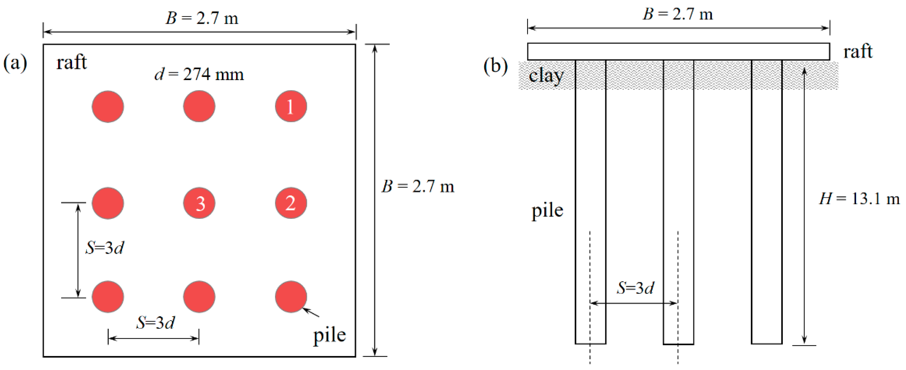
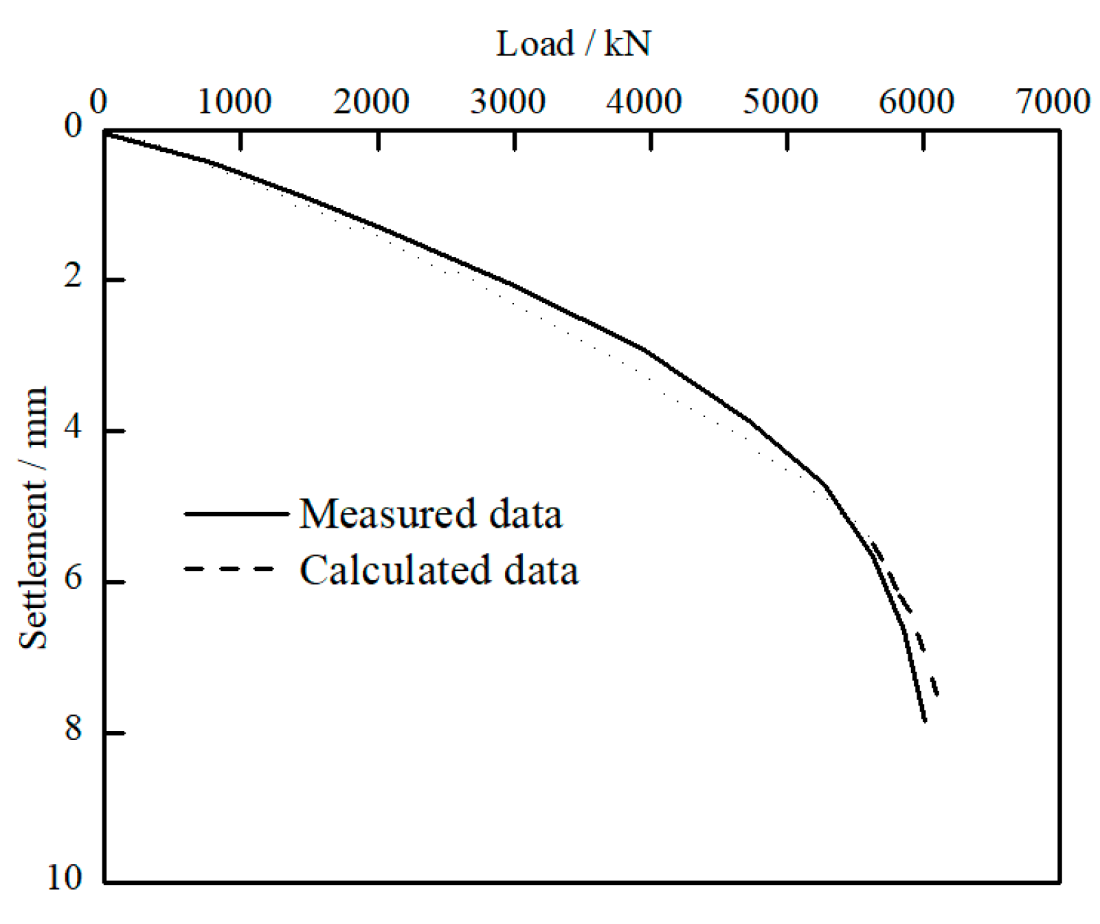
4.1. Case with Mechanical Loading

The first case is from O’Neill et al. [24], where a pile group, comprising 9 closed-ended piles in 3 × 3 setup, was loaded to failure in stiff over-consolidated clay. The pile group configuration is presented in Figure 3. The pile had a diameter (d) of 274 mm, a wall thickness (t) of 9.3 mm, an embedment depth (H) of 13.1 m and a center-to-center spacing (s) of 822 mm. The side length (B) of the square raft was 2.7 m. Castelli and Maugeri [25] evaluated the field soil properties based on the back analysis of the data from O’Neill et al. [24]. According to Castelli and Maugeri [25], the shear modulus for soil (Es) close to the ground surface was 47.9 MPa, which increased linearly with depth to 151 MPa at the pile base. The unit shaft resistance (fs) increased linearly from 19 MPa to 93 MPa. The ultimate unit base resistance (qb) was 2.15 MPa and Poisson’s ratio (μs′) was set as 0.5. The soil deformation modulus (E) was set as 1.95 × 10⁵ kPa and the Young’s modulus (G) for the pile was 2.1 × 10⁸ kPa.
Based on the above parameters, the load response of the pile group is calculated based on the proposed method. As shown in Figure 4, the trend of the calculated Q-S curve is basically consistent with the test data. At initial loading stage, pile group settlement increases linearly with load. At a load level around 5600 kN, a sudden drop occurs. This may indicate that the pile reaches its ultimate state, pile displacement increases rapidly, which leads to the failure of the pile group. Based on the Q-S curve, the ultimate capacity of the pile group is determined as 5600 kN.
To further analyze the load response of pile group foundation, load variations for different piles against the total load is presented in Figure 5. The calculated load shared by different piles shows good agreement with the measured value. Also, the difference of the load value at different locations is minimal; this may be due to the constraint effect of the raft. However, a difference still exists. It seems that piles located at the diagonal corner bear the largest load and pile at the center supports the minimum weight. When the total load is 809 kN, the loads supported by the center pile are 10.4% (calculated) and 10.2% (measured) smaller than that by the diagonal pile. When the total load is 5324 kN, these values are 8.6% (calculated) and 6.2% (measured), respectively. Based on the above analysis, it is believed that the proposed method could be used to simulate the load response of the pile group.

4.2. Case with Thermomechanical Loading

The second case is from Jeong et al. [11], where a series of 3D numerical models were constructed to analyze the influence of thermal loading, pile spacing, active pile location, and pile end restraint on the bearing performance of energy pile group. The selected case is based on a 3 × 3 pile group, with 3 thermally-active piles and 6 non-active piles. The location of the energy pile is shown in Figure 6. The pile was made of pre-tensioned spun high strength concrete, with a diameter (d) of 500 mm and pile length (L) of 20 m. The side length (B) of the square raft was 6.5 m, with thickness (t) of 1 m. Pile heads were rigidly connected to the raft. The Young’s modulus (G) of the numerical soil was 50 kPa, Poisson’s ratio (μs′) was 0.3, friction angle (φ) was 35°. The pile shaft stress (fs) was 120 kPa and the ultimate base stress (qb) was 1150 kPa; the soil shear modulus (Es) was 13.6 MPa. The validation scenario is that the temperature is cooled down by 9 °C and the external load is 9 MN. The focus is on the influence of pile spacing on the development of axial force and settlement of pile group.
The influence of pile spacing on the distribution of axial force of energy piles is illustrated in Figure 7. At pile spacing of 3d, the diagonal pile supports the largest load while the center pile bears the minimum load. And the axial force deceases with increasing distance to the pile top. When pile spacing increases to 5d, the axial force of the center pile shows a noticeable increase while the axial forces for piles at the side and diagonal corner are basically at the same level. This may be explained by the weaker “group effect” at larger pile spacing [26,27]. When pile spacing is small, the center pile would be dragged by the surrounding pile. This dragging effect would limit the relative displacement among piles, which further influences the development of shaft resistance of the center pile. As pile spacing increases, the bearing capacity of center pile increases and bearing performance of the pile group is improved. Another finding is that at pile spacing of 5d, the calculated axial force is obviously smaller that the numerical results, especially at the lower part the pile. It seems that the analytical model produces better prediction of axial force at small pile spacing. This may be the result of simplification of the raft-soil interaction in the proposed method. When pile spacing is small, the pile group works as a whole and the influence of pile raft is less obvious. When pile spacing increases, the influence of raft-soil interaction needs to be considered. On this basis, the proposed model is recommended for pile raft foundation with small pile spacing.
The influence of thermal load and pile spacing on pile top settlement is presented in Figure 8. Since piles are assumed to be rigidly connected to the raft, pile top displacement is the same under sole mechanical load. When piles are under thermal load, the cooling process would lead to contraction of the pile body, thus increasing pile deformation. It can be seen that the largest settlement occurs on the diagonal pile, this is in agreement with the numerical result. When pile spacing decreases to 3d, pile settlement increases. This is the result of group effect that limits the full development of soil resistance, especially for soil around the center pile.

5. Analysis of the Bearing Performance of Energy Pile Group

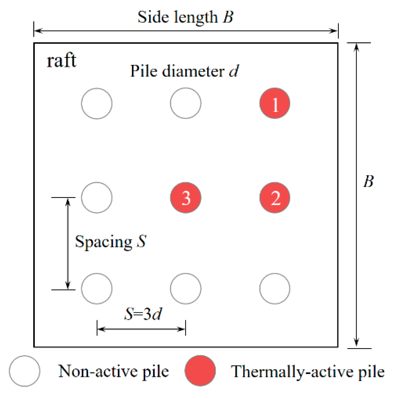
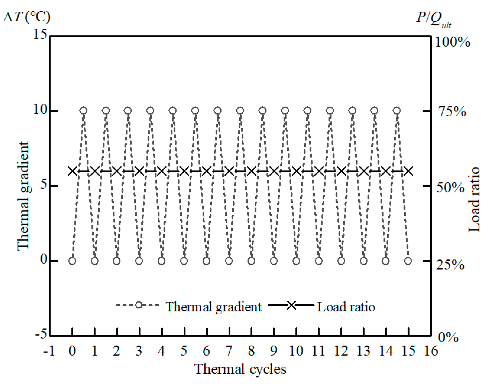
5.1. Simulation Background

In practice, there will be thermally active piles and non-active piles in an energy pile group. The influence of thermal cycles on the loading and deformation characteristics of active piles has been studied based on the above analysis. However, the influence of thermal loading on the bearing behavior of non-active piles and the whole pile group is not clear.
In this section, the proposed analytical approach is further applied to analyze the influence of thermal activity on the bearing behavior of energy pile group based on the field test parameters from O’Neill et al. [24]. The geometrical and mechanical parameters of the pile raft system and the soil foundation keep the same as in Section 4.1, while the pile sequence number is modified according to Figure 2. The main difference is that pile 1, which locates at the diagonal corner, serves as a thermally active pile. Pile 1 suffers 15 cycles of heating and cooling and the total load on the pile raft is 3000 N, which is 52.9% of the ultimate bearing capacity of the pile group. Detailed information of the loading scheme is provided in Figure 9. The focus of this simulation is to reveal the thermal influence on the development of axial force and settlement of non-active piles.

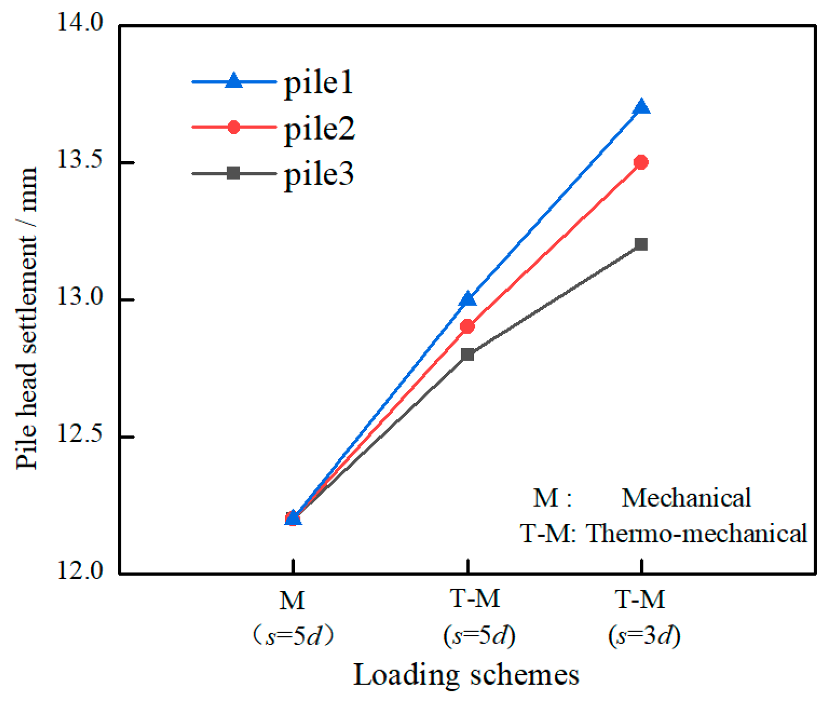
5.2. Simulation Results

Figure 10 shows the influence of thermal cycles on the development of pile top settlement. For pile 1, the active pile, a 61% increase of settlement compared to that under only mechanical load can be observed after 15 thermal cycles. During the continuous heating and cooling process, pile body experiences repeated expansion and contraction. This cyclic deformation would lead to the cyclic shearing of surrounding soil, which further induces degradation of shaft resistance and accumulation of plastic deformation. As for pile 2, a non-active pile surrounding pile 1, a 30% increase of settlement can also be observed. The settlement of pile 2 may be due to the constraint effect of pile raft, as piles are all rigidly connected to the pile raft and the settlement of pile 1 would drag pile 2 downwards. As a result, the increase of settlement is not as remarkable as for pile 1. As for pile 7 and 9, which locate at the opposite side of the raft, a reverse trend of settlement development occurs. A notable lift of pile position, around 58% of the initial settlement, occurs for pile 9, which locates at opposite diagonal corner to pile 1. It seems that pile 7 and pile 9 are pulled out by the pile raft, which indicates the rotation movement of pile group along the connecting line of pile 4 and pile 6. The differential settlement caused by thermal loading would pose a great threat to the long-term stability of the superstructure, thus it is necessary to select the location of active piles properly in energy pile group.
The variation of axial force on pile 1 after the first heating is presented in Figure 11. After mechanical loading, the axial force decreases along the pile length. At pile bottom, the base resistance is 77 kN, which is about 22.5% of the total load on the pile head. The distribution of axial force follows the same trend for other piles, as all piles are assumed to be rigidly connected to the pile raft and external load is uniformly applied to the pile raft. After the first heating, the axial force of pile 1 shows an obvious increase, while the axial force of pile 2 decreases slightly, especially at the upper part. It is believed that heating pile 1 would lead to expansion of the pile body, which further increases the axial force due to the constraint of pile raft. The upward movement of pile 1 would pull the surrounding non-active pile 2 upwards, as a result, the axial force of pile 2 decreases slightly. For pile 4, which locates on the rotation axis of pile group (as revealed from Figure 10), the influence of heating on the distribution of axial force is minimal. As for pile 9, the rotation of pile raft would lead to the compression of pile body. As a result, the axial force of pile 9 increases, though with smaller magnitude than that of pile 1.
To better understand the influence of thermal cycles on the loading performance, variations of the pile head load on pile 1 and pile 2 at different thermal stages are presented in Figure 12. For pile 1, heating will lead to the expansion of pile body, which further induces the increase of pile head load due to the constraint of pile raft, while the following cooling process will cause pile contraction. After the first heating and cooling cycle, the pile head load is smaller than that after mechanical loading. With continuous heating and cooling, load on pile 1 keeps decreasing. And the load variations due to thermal cycles gradually stabilizes at around 4~5 cycles. For pile 2, the load variance shows a reverse trend. Heating on pile 1 will lead to load decrease on pile 2. After each thermal cycle, there will be a slight increase of the pile head load, and load variance also decreases with increasing thermal cycles. After 15 heating and cooling cycles, pile head loads on pile 1 and pile 2 increase by 20% and 8.5%, compared to that under mechanical loading.
The continuous heating and cooling process will cause the repeated expansion and contraction of the energy pile. Due to the constraint of pile raft, differential settlement may occur for piles at different location, which would further lead to the stress redistribution of each pile and influence the long-term bearing performance of energy pile group. According to the above analysis, the effect of thermal loading on the pile group behavior is very complex and depends on pile spacing, active pile number, active pile locations, etc. The proposed analytical approach is expected to provide a preliminary evaluation of the energy group design before sophisticated numerical modelling and experimental research.

6. Conclusions

(1) In this paper, a simple and convenient analytical approach is proposed to evaluate the thermal effect on the bearing characteristics of energy group pile. The nonlinear pile-soil interaction is simulated based on an exponential model and the axial load transfer (τ-z) method is used to calculated the distribution of shear stress. The thermomechanical behavior is simplified as mechanical and thermal load.
(2) The proposed method shows good prediction of axial force distribution for pile raft foundations with small pile spacing. When pile spacing increases, the influence of raft-soil interaction needs to be considered.
(3) For energy pile group with thermally-active piles and non-active piles, the heat exchange of the energy pile may cause differential settlement and redistribution of axial force of the pile group. This thermal effect is highly related to pile spacing, energy pile number, and energy pile location.
(4) For energy pile located at the corner of the pile group, thermal cycles would lead to the rotation of the whole structure. During heating, load on the head of energy pile would increase due to the interaction between pile and raft. With continuous heating and cooling, pile head settlement gradually accumulates and load decreases. For non-active piles in the pile group, the settlement and load behavior may differ at different location.

Author Contributions

L.L.: Analytical analysis, Writing—Original draft. L.D.: Analytical analysis, Writing—Original draft. C.L.: Project administration, Funding acquisition, Conceptualization, Writing—Review & Editing. W.W.: Formal analysis, Data Curation. M.W.: Formal analysis, Data Curation. R.L.: Formal analysis, Data Curation. All authors have read and agreed to the published version of the manuscript.

Funding

This research is supported by the National Natural Science Foundation of China (Grant Nos. 51878634, 52178371, 52178321, 51878185), the Outstanding Youth Project of Natural Science Foundation of Zhejiang Province (Grant No. LR21E080005), the Young Elite Scientists Sponsorship Program by CAST (Grant No. 2018QNRC001), the Fundamental Research Founds for National University, China University of Geosciences (Wuhan) (Grant Nos. CUGGC09, 1910491A15, 1910491T04). The Innovative Research Team Program of Guangxi Natural Science Foundation (Grant No. 2016GXNSFGA380008), the China Postdoctoral Science Foundation Funded Project (Grant No. 2020M673093), and the Systematic Project of Guangxi Key Laboratory of Disaster Prevention and Structural Safety (Grant Nos. 2019ZDK047, 2019ZDK049) are also acknowledged.

Institutional Review Board Statement

Not applicable.

Informed Consent Statement

Not applicable.

Data Availability Statement

All the data used in this research can be easily accessible by downloading the various documents appropriately cited in the paper.

Conflicts of Interest

The authors declare no conflict of interest.

References

  1. Kong, G.; Fang, J.; Huang, X.; Liu, H.; Abuel-Naga, H. Thermal induced horizontal earth pressure changes of pipe energy piles under multiple heating cycles. Geomech. Energy Environ. 2020, 26, 100228. [Google Scholar] [CrossRef]
  2. Maragna, C.; Loveridge, F. A New Approach for Characterizing Pile Heat Exchangers Using Thermal Response Tests. Energies 2021, 14, 3375. [Google Scholar] [CrossRef]
  3. Jensen-Page, L.; Loveridge, F.; Narsilio, G. Thermal Response Testing of Large Diameter Energy Piles. Energies 2019, 12, 2700. [Google Scholar] [CrossRef] [Green Version]
  4. Ng, C.W.W.; Chao, S.; Gunawan, A.; Laloui, L.; Liu, H. Centrifuge modelling of heating effects on energy pile performance in saturated sand. Can. Geotech. J. 2014, 52, 150113073645001. [Google Scholar] [CrossRef]
  5. Suryatriyastuti, M.; Burlon, S.; Mroueh, H. On the understanding of cyclic interaction mechanisms in an energy pile group. Int. J. Numer. Anal. Methods Geomech. 2015, 40, 3–24. [Google Scholar] [CrossRef]
  6. Farhangi, V.; Karakouzian, M.; Geertsema, M. Effect of Micropiles on Clean Sand Liquefaction Risk Based on CPT and SPT. Appl. Sci. 2020, 10, 3111. [Google Scholar] [CrossRef]
  7. Mimouni, T.; Laloui, L. Behaviour of a group of energy piles. Can. Geotech. J. 2015, 52. [Google Scholar] [CrossRef]
  8. Peng, H.; Kong, G.; Liu, H.; Abuel-Naga, H.; Hao, Y. Thermomechanical Behaviour of Floating Energy Pile Groups in Sand. J. Zhejiang Univ. Sci. A 2018, 19, 638–649. [Google Scholar] [CrossRef]
  9. Fang, J.; Kong, G.; Meng, Y.; Wang, L.; Yang, Q. Thermomechanical Behavior of Energy Piles and Interactions within Energy Pile–Raft Foundations. J. Geotech. Geoenvironmental Eng. 2020, 146, 04020079. [Google Scholar] [CrossRef]
  10. Afsharhasani, R.; Karakouzian, M.; Farhangi, V. Effect of Competent Caliche Layers on Measuring the Capacity of Axially Loaded Drilled Shafts Using the Osterberg Test. Appl. Sci. 2020, 10, 6169. [Google Scholar] [CrossRef]
  11. Jeong, S.; Lim, H.; Lee, J.K.; Kim, J. Thermally induced mechanical response of energy piles in axially loaded pile groups. Appl. Therm. Eng. 2014, 71, 608–615. [Google Scholar] [CrossRef]
  12. Salciarini, D.; Ronchi, F.; Cattoni, E.; Tamagnini, C. Thermomechanical Effects Induced by Energy Piles Operation in a Small Piled Raft. Int. J. Geomech. 2013, 15. [Google Scholar] [CrossRef]
  13. Di Donna, A.; Laloui, L. Numerical analysis of the geotechnical behaviour of energy piles. Int. J. Numer. Anal. Methods Geomech. 2014, 39. [Google Scholar] [CrossRef]
  14. Saggu, R.; Chakraborty, T. Thermomechanical Response of Geothermal Energy Pile Groups in Sand. Int. J. Geomech. 2016, 16, 04015100. [Google Scholar] [CrossRef]
  15. Knellwolf, C.; Péron, H.; Laloui, L. Geotechnical Analysis of Heat Exchanger Piles. J. Geotech. Geoenviron. Eng. 2011, 137. [Google Scholar] [CrossRef]
  16. Frank, R.; Zhao, S.R. Estimation par les paramètres pressiométriques de 1′ enfoncement sous charge axiale de pieux forés dans des sols fins. Bull. Liaison Lab. Ponts Chauss 1982, 119, 17–24. [Google Scholar]
  17. Chen, D.; McCartney, J. Parameters for Load Transfer Analysis of Energy Piles in Uniform Nonplastic Soils. Int. J. Geomech. 2016, 17, 04016159. [Google Scholar] [CrossRef] [Green Version]
  18. Fei, K.; Zhu, Z.; Shi, Y.; Zhou, Y. A simplified method for geotechnical analysis of energy pile groups. Rock Soil Mech. 2020, 41, 3889–3898. [Google Scholar]
  19. Kezdi, A. Bearing capacity of piles and pile groups. In Proceedings of the 4th International Conference on Soil Mechanics & Foundation Engineering, London, UK, 12–24 August 1957; Volume 2, pp. 46–51. [Google Scholar]
  20. Huang, Y.P.; Jiang, G.; Lu, H.W.; Song, Z.; Xu, X.L.; Hong, X. Thermo-mechanical coupling load transfer method of energy pile based on exponential model. J. Nanjing Tech Univ. (Nat. Sci. Ed.) 2019, 41, 96–103. [Google Scholar] [CrossRef]
  21. Randolph, M.; Wroth, C.P. Analysis of Deformation of Vertically Loaded Piles. J. Geotech. Eng. Div. 1978, 104, 1465–1488. [Google Scholar] [CrossRef]
  22. Lee, K.M.; Xiao, Z. A simplified nonlinear approach for pile group settlement analysis in multilayered soils. Can. Geotech. J. 2001, 38, 1063–1080. [Google Scholar] [CrossRef]
  23. Badenes, B.; Magraner, T.; De Santiago, B.C.; Pardo, F.; Urchueguia, J. Thermal Behaviour under Service Loads of a Thermo-Active Precast Pile. Energies 2017, 10, 1315. [Google Scholar] [CrossRef] [Green Version]
  24. O’Neill, M.; Hawkins, R.; Mahar, L. Load Transfer Mechanisms in Piles and Pile Groups. J. Geotech. Eng. Div. 1982, 108, 1605–1623. [Google Scholar] [CrossRef]
  25. Castelli, F.; Maugeri, M. Simplified Nonlinear Analysis for Settlement Prediction of Pile Groups. J. Geotech. Geoenviron. Eng. 2002, 128. [Google Scholar] [CrossRef]
  26. Zhou, Y.; Tokimatsu, K. Numerical evaluation of pile group effect of a composite group. Soils Found. 2018, 58, 353–374. [Google Scholar] [CrossRef]
  27. Souri, A.; Abu-Farsakh, M.; Voyiadjis, G. Evaluating the effect of pile spacing and configuration on the lateral resistance of pile groups. Mar. Georesources Geotechnol. 2020, 39, 1–13. [Google Scholar] [CrossRef]
Figure 1. Load transfer curves under cyclic loading condition: (a) unloading stage; (b) reloading stage.
Energies 14 06881 g001
Figure 2. Layout of energy pile.
Energies 14 06881 g002
Figure 3. Pile group configuration: (a) bird’s eye view; (b) cross-section view.
Energies 14 06881 g003
Figure 4. Load-settlement curve of pile group.
Energies 14 06881 g004
Figure 5. Load variations for piles at different locations.
Energies 14 06881 g005
Figure 6. Layout of energy pile in a pile group.
Energies 14 06881 g006
Figure 7. Development of axial force: (a) pile spacing = 3d; (b) pile spacing = 5d.
Energies 14 06881 g007
Figure 8. Variations of pile top settlement at different loading schemes.
Energies 14 06881 g008
Figure 9. Loading scheme.
Energies 14 06881 g009
Figure 10. Development of pile top settlement with thermal cycles.
Energies 14 06881 g010
Figure 11. Distribution of pile axial force after the first heating.
Energies 14 06881 g011
Figure 12. Variation of pile head load at different thermal stages: (a) pile 1; (b) pile 2.
Energies 14 06881 g012
Publisher’s Note: MDPI stays neutral with regard to jurisdictional claims in published maps and institutional affiliations.

