
Effects of the Multiple Injection Strategy on Combustion and Emission Characteristics of a Two-Stroke Marine Engine


Abstract
:
1. Introduction
2. Simulated Engine and CFD Analysis
2.1. Simulated Engine Specifications
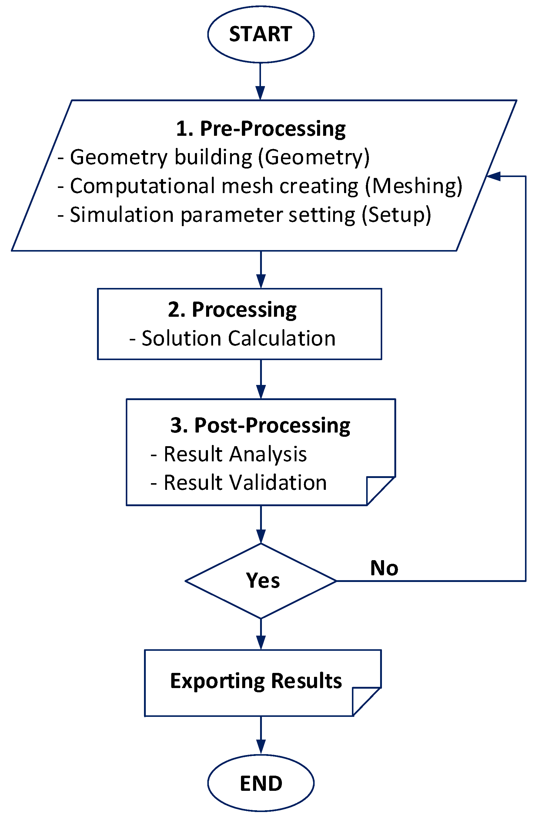
2.2. CFD Analysis
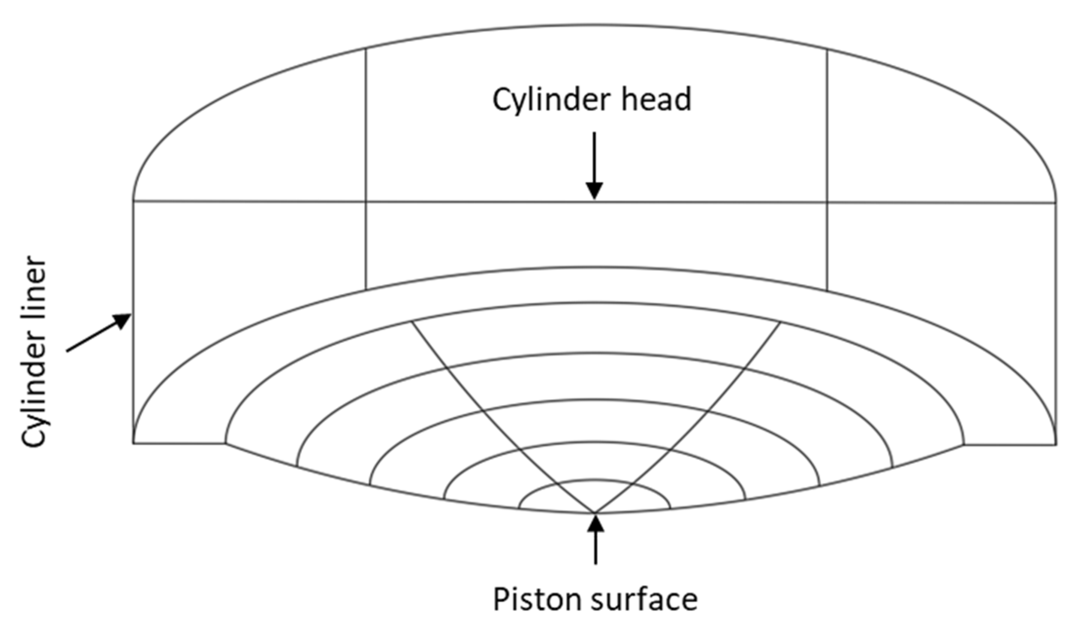
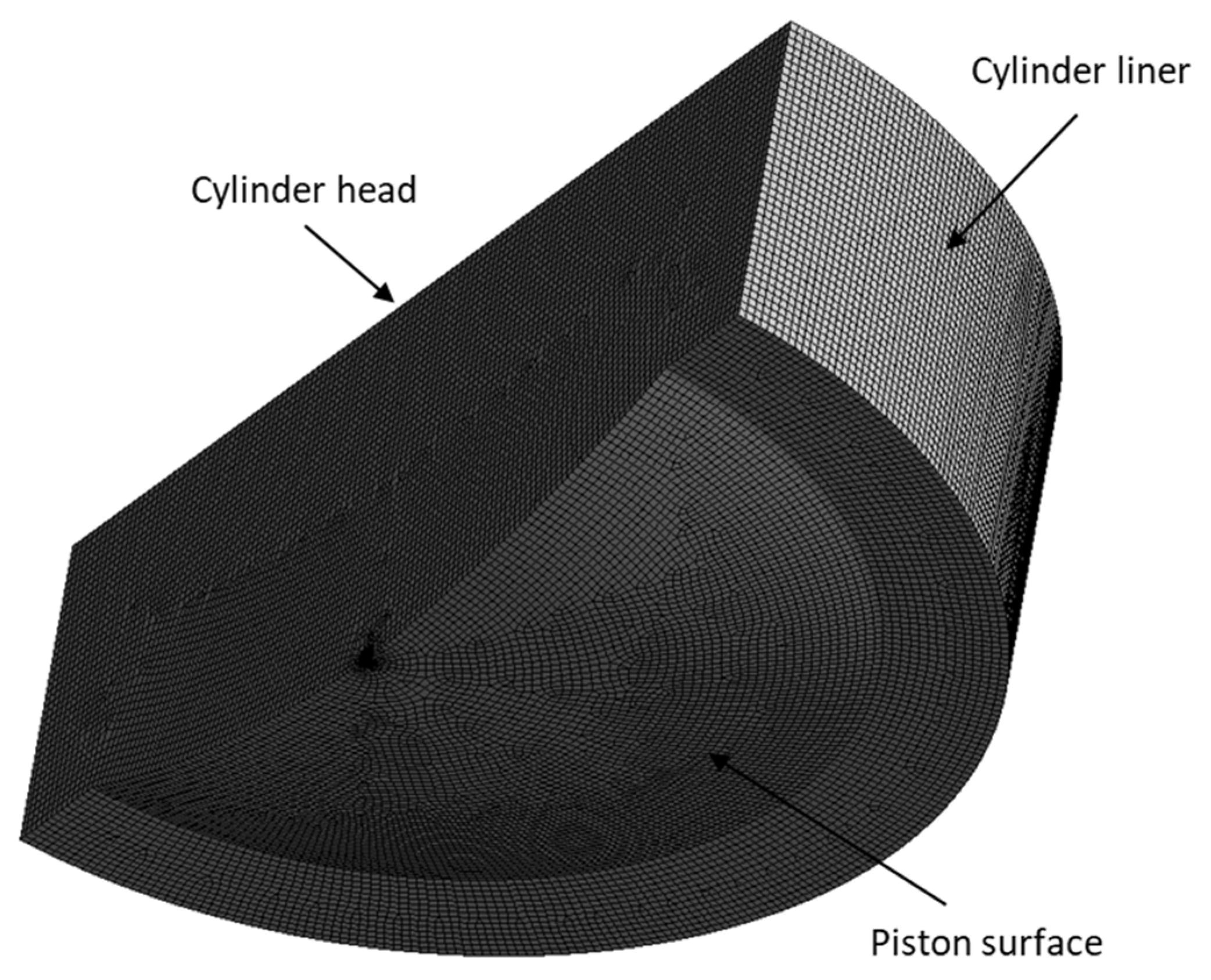
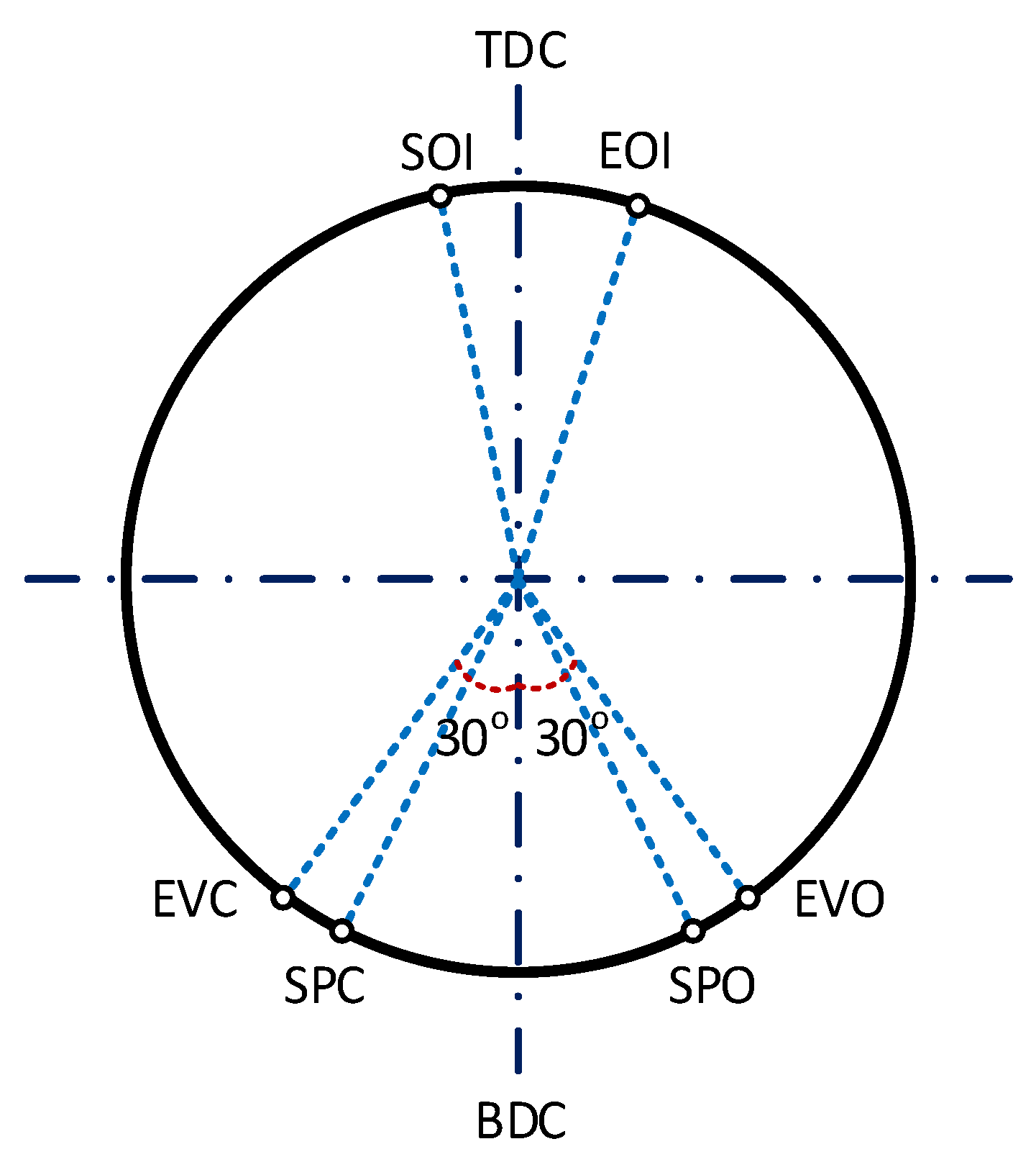
2.3. Computational Mesh, Boundary and Initial Conditions
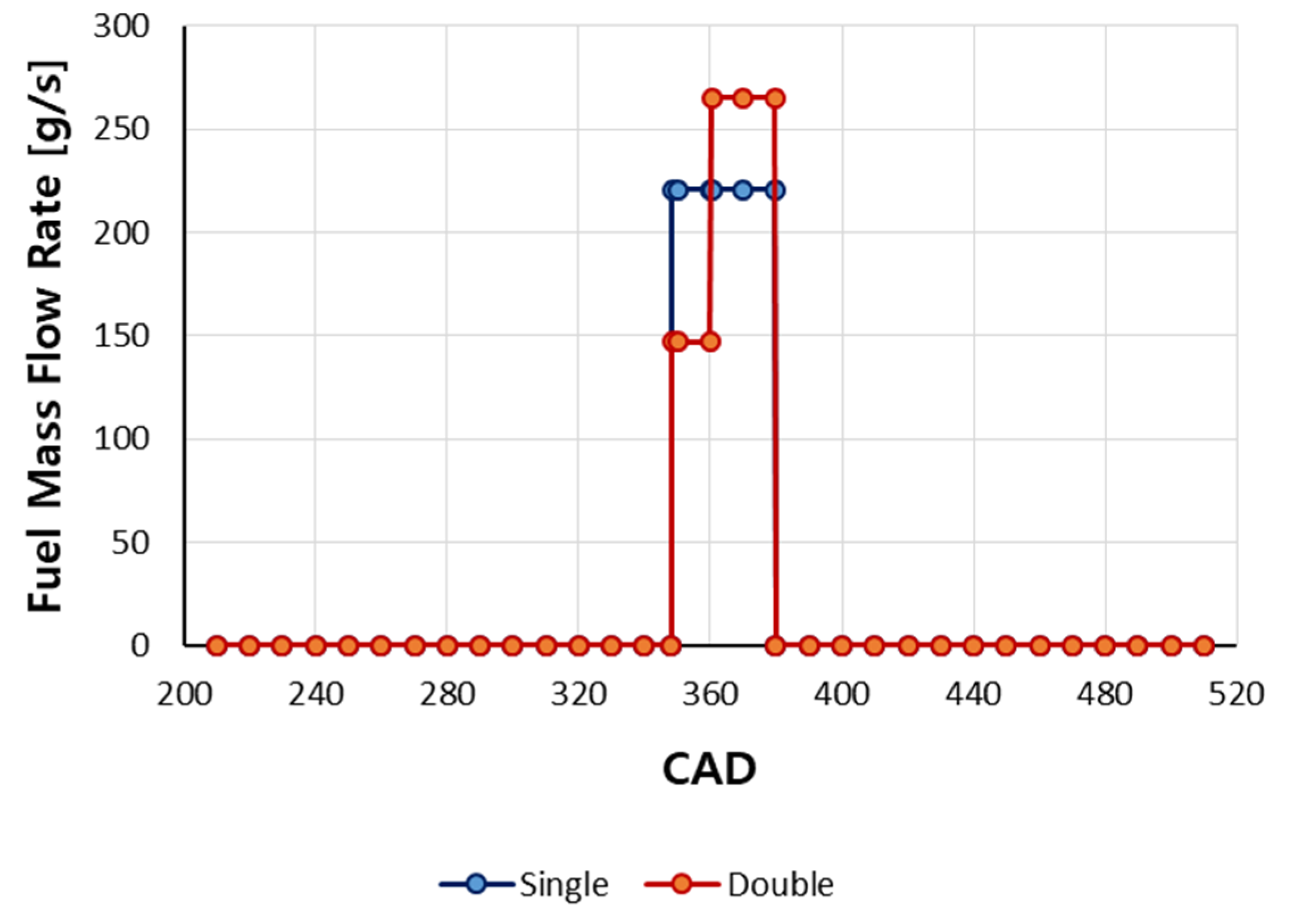
2.4. Simulation Cases and Fuel Properties
3. Simulation Results
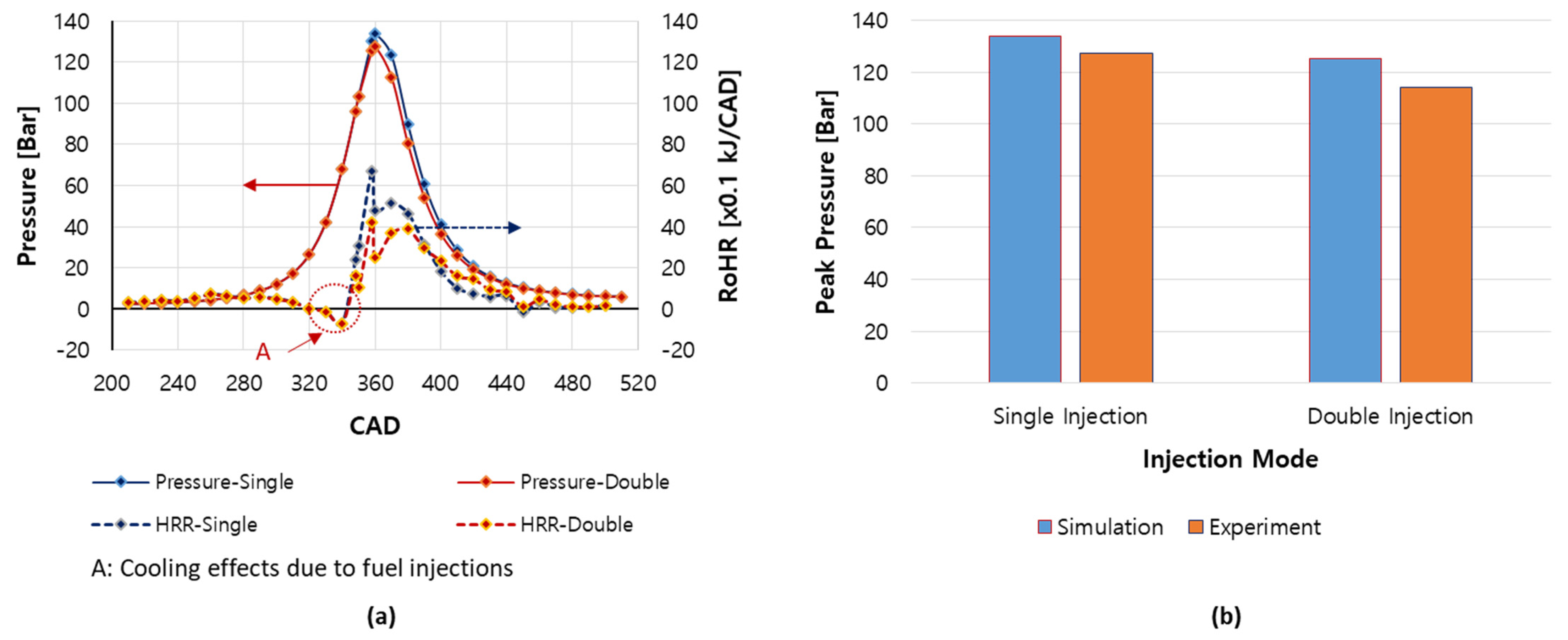
3.1. In-Cylinder Pressure
3.2. In-Cylinder Temperature
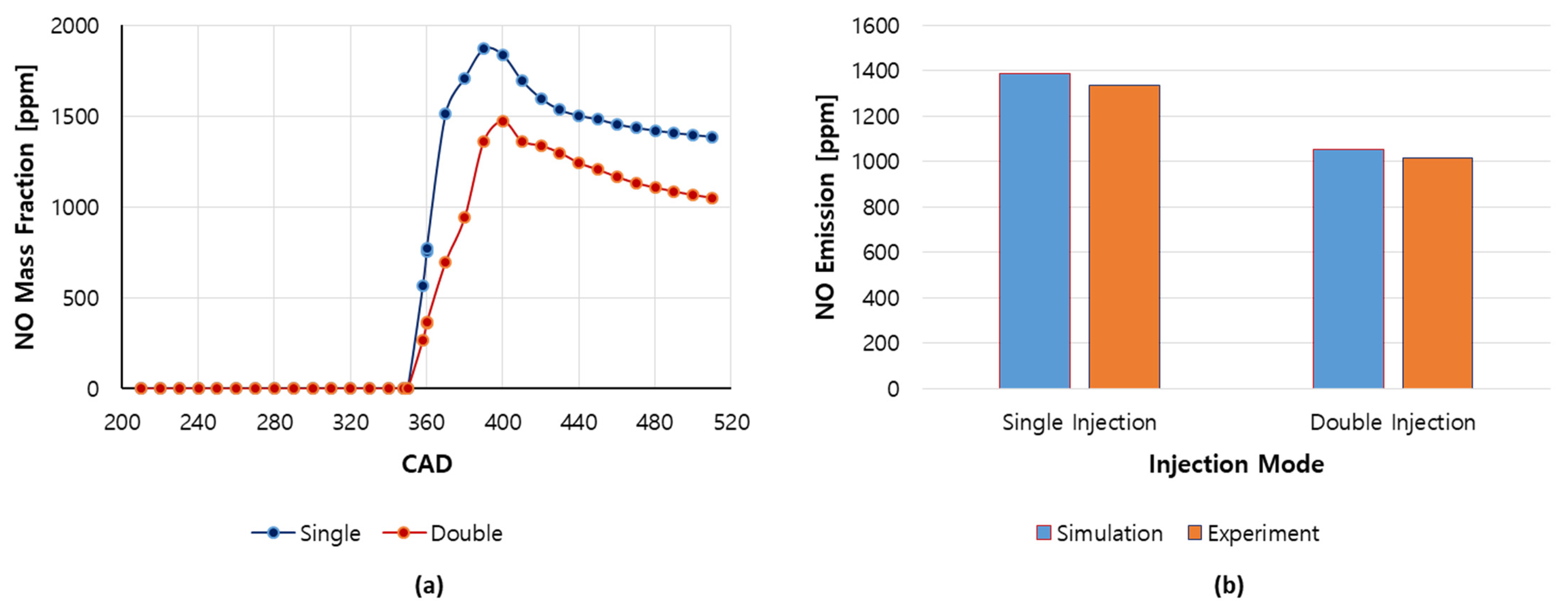
3.3. NO Emission
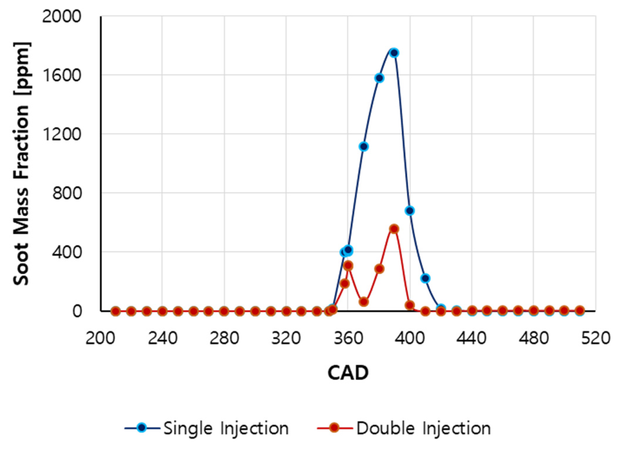
3.4. Soot Formation
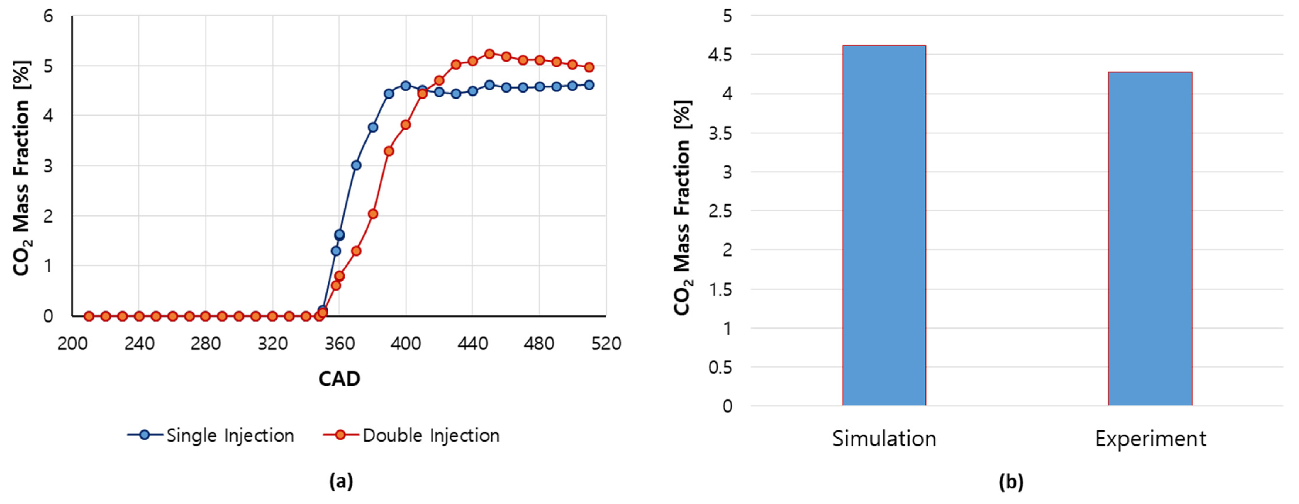
3.5. Carbon Dioxide (CO2) Emission
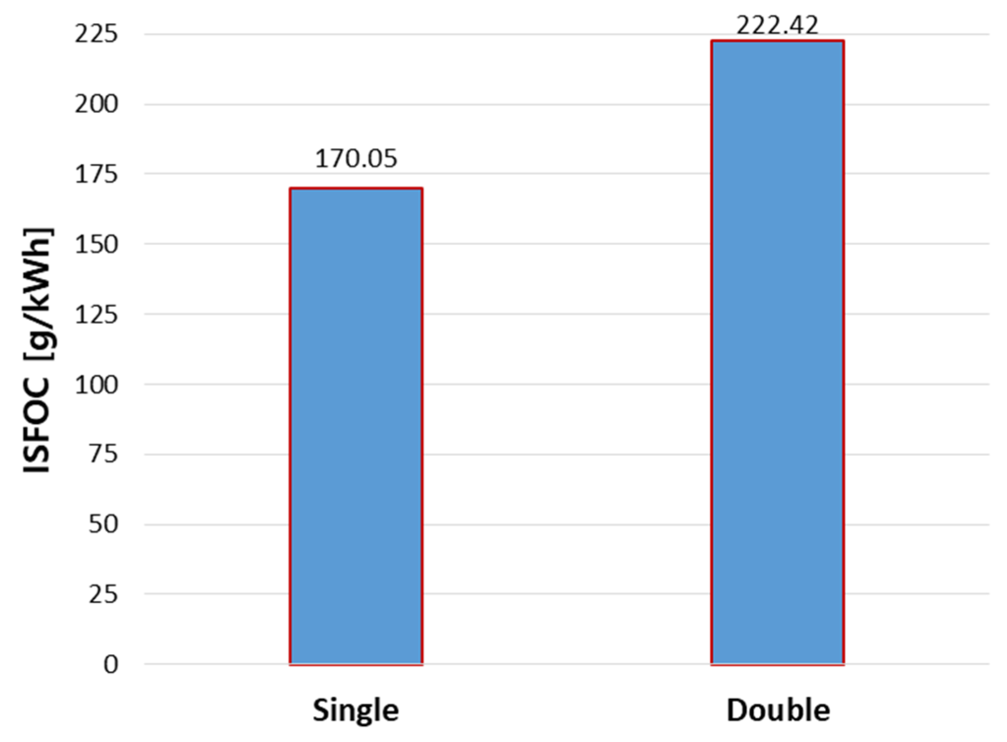
3.6. Specific Fuel Oil Consumption
4. Conclusions
- The in-cylinder peak pressure in the double-injection mode was 6.42% lower compared with the single injection mode.
- The in-cylinder peak temperature in the double-injection mode was lower in comparison with the single-injection mode resulting in a significant reduction in NO emission (24.16%).
- The maximum soot emission generated in the double-injection mode was reduced by more than 68% in comparison with the single-injection mode.
- However, the double-injection strategy increased the CO2 emission (7.58%) and ISFOC (23.55%) compared to the single-injection. These are negative effects of the double-injection strategy on the engine that the operators need to take into consideration when operating the engine.
Author Contributions
Funding
Institutional Review Board Statement
Informed Consent Statement
Data Availability Statement
Conflicts of Interest
References
- Thomson, H.; Corbett, J.J.; Winebrake, J.J. Natural gas as a marine fuel. Energy Policy. 2015, 87, 153–167. [Google Scholar] [CrossRef] [Green Version]
- Woodyard, D. Pounders Marine Diesel Engines and Gas Turbines, 9th ed.; Elsevier: Burlington, MA, USA, 2009. [Google Scholar]
- Pham, V.C.; Choi, J.H.; Rho, B.S.; Kim, J.S.; Park, K.N.; Park, S.K.; Le, V.V.; Lee, W.J. A numerical study on the combustion process and emission characteristics of a natural gas-diesel dual-fuel marine engine at full load. Energies 2021, 14, 1342. [Google Scholar] [CrossRef]
- Pham, V.C.; Rho, B.-S.; Kim, J.-S.; Lee, W.-J.; Choi, J.-H. Effects of various fuels on combustion and emission characteristics of a four-stroke dual-fuel marine engine. J. Mar. Sci. Eng. 2021, 9, 1072. [Google Scholar] [CrossRef]
- Martin, G.C.; Mueller, C.J.; Milam, D.M.; Radovanovic, M.S.; Gehrke, C.R. Early direct-injection, low-temperature combustion of diesel fuel in an optical engine utilizing a 15-hole, dual-row, narrow-included-angle nozzle. SAE Int. J. Engines 2008, 1, 1057–1082. [Google Scholar] [CrossRef]
- Polonowski, C.J.; Mueller, C.J.; Gehrke, C.R.; Bazyn, T.; Martin, C.M.; Lillo, M. An experimental investigation of low-soot and soot-free combustion strategies in a heavy-duty, single-cylinder, direct-injection, optical diesel engine. SAE Int. J. Fuels Lubr. 2012, 5, 51–77. [Google Scholar] [CrossRef]
- Dunn-Rankin, D. Lean Combustion Technology and Control; Elsevier Ltd.: Amsterdam, The Netherlands; Academic Press: Boston, MA, USA, 2011. [Google Scholar]
- Belgiorno, G.; Boscolo, A.; Dileo, G.; Numidi, F.; Pesce, F.C.; Vassallo, A.; Ianniello, R.; Beatrice, C.; Blasio, G.D. Experimental study of additive-manufacturing-enabled innovative diesel combustion bowl features for achieving ultra-low emissions and high efficiency. SAE Int. J. Adv. Curr. Pract. Mobil.-V130-99EJ 2021, 3, 672–684. [Google Scholar] [CrossRef]
- Nehmer, D.A.; Reitz, R.D. Measurement of the effect of injection rate and split injections on diesel engine soot and NOx emissions. SAE Pap. 1994, 940668. [Google Scholar]
- Tow, T.C.; Pierpont, D.A.; Reitz, R.D. Reducing particulate and NOx emissions by using multiple injections in a heady duty DI diesel engine. SAE Pap. 1994, 940897. [Google Scholar]
- Han, Z.; Uludogan, A.; Hampson, G.J.; Reitz, R.D. Mechanism of soot and NOx emission reduction using multiple injection in a diesel engine. SAE Pap. 1996, 960633. [Google Scholar]
- Montgomery, D.T.; Reitz, R.D. Six-mode cycle evaluation of the effect of EGR and multiple injections on particulate and NOx emissions from a DI diesel engine. SAE Tech. Pap. 1996, 960316. [Google Scholar]
- Pierpont, D.A.; Montgomery, D.T.; Reitz, R.D. Reducing particulate and NOx using multiple injections and EGR in a D.I. diesel. J. Fuels Lubr. 1995, 104, 171–183. [Google Scholar]
- Zhang, L. A study of pilot injection in a DI diesel engine. SAE Pap. 1999, 1, 3493. [Google Scholar]
- Chen, S.K. Simultaneous reduction of NOx and particulate emissions by using multiple injections in a small diesel engine. SAE Pap. 2000, 1, 3084. [Google Scholar]
- Tanaka, T.; Ando, A.; Ishizaka, K. Study on pilot injection of DI diesel engine using common rail injection system. JSAE Rev. 2002, 23, 297–302. [Google Scholar] [CrossRef]
- Choi, C.Y.; Reitz, R.D. An experimental study on the effects of oxygenated fuel blends and multiple injection strategies on DI diesel engine emissions. Fuel 1999, 78, 1303–1317. [Google Scholar] [CrossRef]
- Fang, T.; Coverdill, R.E.; Lee, C.F.; White, R.A. Effects of injection angles on combustion processes using multiple injection strategies in an HSDI diesel engine. Fuel 2008, 87, 3232–3239. [Google Scholar] [CrossRef]
- Chacko, N.; Rajkumar, S.; Thanragaja, J. Experimental and modeling analysis of multiple-injection strategies with B20 operation in a CRDI engine. Fuel 2021, 293, 120433. [Google Scholar] [CrossRef]
- Plamondon, E.; Seers, P. Parametric study of pilot–main injection strategies on the performance of a light-duty diesel engine fueled with diesel or a WCO biodiesel–diesel blend. Fuel 2019, 236, 1273–1281. [Google Scholar] [CrossRef]
- Jorques Moreno, C.; Stenlaas, O.; Tunestal, P. Influence of small pilot on main injection in a heavy-duty diesel engine. SAE Tech. Pap. 2017, 1, 708. [Google Scholar] [CrossRef]
- Qiu, L.; Cheng, X.; Liu, B.; Dong, S.; Bao, S.Z. Partially premixed combustion based on different injection strategies in a light-duty diesel engine. Energy 2016, 96, 155–165. [Google Scholar] [CrossRef]
- Yang, S.Y.; Chung, S.H. An experimental study on the effects of high-pressure and multiple injection strategies on DI diesel engine emissions. In SAE Technical Paper Series; SAE International: Warrendale, PA, USA, 2013. [Google Scholar]
- Durbin, P.A. Near-wall turbulence closure modeling without “damping functions”. Theor. Comput. Fluid Dyn. 1991, 3, 1–13. [Google Scholar]
- ANSYS Fluent Theory Guide; ANSYS, Inc.: Canonburg, PA, USA, 2013; Available online: http://www.ansys.com (accessed on 7 July 2021).
- Rao, V.; Honnery, D. A comparison of two NOx prediction schemes for use in diesel engine thermodynamic modelling. Fuel 2013, 107, 662–670. [Google Scholar] [CrossRef]
- Brookes, S.; Moss, J. Predictions of soot and thermal radiation properties in confined turbulent jet diffusion flames. Combust. Flame. 1999, 116, 486–503. [Google Scholar] [CrossRef]
- PubChem Compound. n-heptane–Compound Summary. National Center for Biotechnology Information. 8600 Rockville Pike, Bethesda MD, 20894 USA. 16 September 2004. Available online: https://pubchem.ncbi.nlm.nih.gov/compound/8900 (accessed on 7 September 2020).
- Friend, D.G.; Ely, J.F. and Ingham, H. Thermophysical properties of methane. J. Phys. Chem. Ref. Data 1989, 18, 583. [Google Scholar] [CrossRef]
- Heywood, J.B. Internal Combustion Engine Fundamentals; McGraw-Hill Education: New York, NY, USA, 1998. [Google Scholar]
- Wei, L.; Geng, P. A review on natural gas/diesel dual fuel combustion, emissions and performance. Fuel Process. Technol. 2016, 142, 264–278. [Google Scholar] [CrossRef]
- Kuo, K.K. Principles of Combustion, 2nd ed.; John Wiley and Sons: New York, NY, USA, 2005. [Google Scholar]
- Maricq, M.M.; Chase, R.E.; Xu, N.; Laing, P.M. The effects of the catalytic converter and fuel sulfur level on motor vehicle particulate matter emissions: Light duty diesel vehicles. Environ. Sci. Technol. 2002, 36, 283–289. [Google Scholar] [CrossRef]
- Burnett, R.T.; Cakmak, S.; Brook, J.R.; Krewski, D. The role of particulate size and chemistry in the association between summertime ambient air pollution and hospitalization for cardiorespiratory diseases. Environ. Health Perspect. 1997, 105, 614–620. [Google Scholar] [CrossRef]
- Kittelson, D.B.; Watts, W.F.; Johnson, J.P. On-road and laboratory evaluation of combustion aerosols -part 1: Summary of diesel engine results. J. Aerosol Sci. 2006, 37, 913–930. [Google Scholar] [CrossRef]
- Rounce, P.; Tsolakis, A.; York, S.A.P.E. Speciation of particulate matter and hydrocarbon emissions from biodiesel combustion and its reduction by after-treatment. Fuel 2012, 96, 90–99. [Google Scholar] [CrossRef]
- Tree, D.R.; Svensson, K.I. Soot processes in compression ignition engines. Prog. Energy Combust. Sci. 2007, 33, 272–309. [Google Scholar] [CrossRef]
- Smith, O.I. Fundamentals of soot formation in flames with application to diesel engine particulate emissions. Prog. Energy Combust. Sci. 1981, 7, 275–291. [Google Scholar] [CrossRef]
- Gowthaman, S.; Sathiyagnanam, A.P. Effects of charge temperature and fuel injection pressure on HCCI engine. Alex. Eng. J. 2016, 55, 119–125. [Google Scholar] [CrossRef] [Green Version]
- Pan, W.; Yao, C.; Han, G.; Wei, H.; Wang, Q. The impact of intake air temperature on performance and exhaust emissions of a diesel methanol dual fuel engine. Fuel 2015, 162, 101–110. [Google Scholar] [CrossRef]


| Parameter | Value | Unit |
|---|---|---|
| Type of Engine | 2-Stroke Diesel Engine | |
| Name of Engine | 6L42MC-ME | |
| No. of Cylinder | 6 | |
| Cylinder Bore × Stroke | 420 × 1360 | mm |
| Connecting Rod Length | 1700 | mm |
| Compression Ratio | 13.5 | |
| Rated Power @ Rated Speed | 4485 @ 160 | kW @ rpm |
| IMEP | 18 | bar |
| No. of Fuel Injector | 2 | |
| Fuel | Diesel (C10H22) | |
| LCV of Diesel | 42,343 * | kJ/kg |
| Model | Description | |
|---|---|---|
| Combustion | Non-premixed Combustion model [25] | |
| Emission | NO | Extended Zeldovich |
| Soot | Moss-Brookes model | |
| Atomization | Spray | Discrete Phase Model (DPM) |
| Breakup | KHRT | |
| Ignition | Auto-ignition | |
| Collision | Stochastic Collision model | |
| Turbulence | k- turbulence model | |
| Mesh Statistics and Quality | |
|---|---|
| Type of elements | Hexahedral |
| No. of nodes at the TDC | 459,058 |
| No. of elements at the TDC | 508,650 |
| Aspect ratio | 17.05 |
| Maximum Skewness ratio | 0.76 |
| Minimum Orthogonal quality | 0.45 |
| Boundary Conditions | Boundary Type/Specific Condition |
|---|---|
| Cylinder head | Wall/Temp./297 °C |
| Piston | Mesh movement/Temp./297 °C K |
| Liner | Wall/Temp./197 °C |
| Segment cut | Cyclic |
| Initial conditions | Value |
| Scavenging air Press. | 2.0 bar |
| Scavenging air Temp. | 28 °C |
| EVC | 30 CAD ABDC |
| EVO | 30 CAD BBDC |
| SOI | 12 CAD BTDC |
| Injection duration | 32 CAD |
Publisher’s Note: MDPI stays neutral with regard to jurisdictional claims in published maps and institutional affiliations. |
© 2021 by the authors. Licensee MDPI, Basel, Switzerland. This article is an open access article distributed under the terms and conditions of the Creative Commons Attribution (CC BY) license (https://creativecommons.org/licenses/by/4.0/).
Share and Cite
Seol, J.-H.; Pham, V.C.; Lee, W.-J. Effects of the Multiple Injection Strategy on Combustion and Emission Characteristics of a Two-Stroke Marine Engine. Energies 2021, 14, 6821. https://doi.org/10.3390/en14206821
Seol J-H, Pham VC, Lee W-J. Effects of the Multiple Injection Strategy on Combustion and Emission Characteristics of a Two-Stroke Marine Engine. Energies. 2021; 14(20):6821. https://doi.org/10.3390/en14206821
Chicago/Turabian StyleSeol, Ju-Hwan, Van Chien Pham, and Won-Ju Lee. 2021. "Effects of the Multiple Injection Strategy on Combustion and Emission Characteristics of a Two-Stroke Marine Engine" Energies 14, no. 20: 6821. https://doi.org/10.3390/en14206821
APA StyleSeol, J.-H., Pham, V. C., & Lee, W.-J. (2021). Effects of the Multiple Injection Strategy on Combustion and Emission Characteristics of a Two-Stroke Marine Engine. Energies, 14(20), 6821. https://doi.org/10.3390/en14206821