
Variable DC-Link Voltage Control of Dual Active Bridge Converter in a Standalone Wind Power Generation System for High-Efficiency Battery-Discharging Operation †


Abstract
:1. Introduction
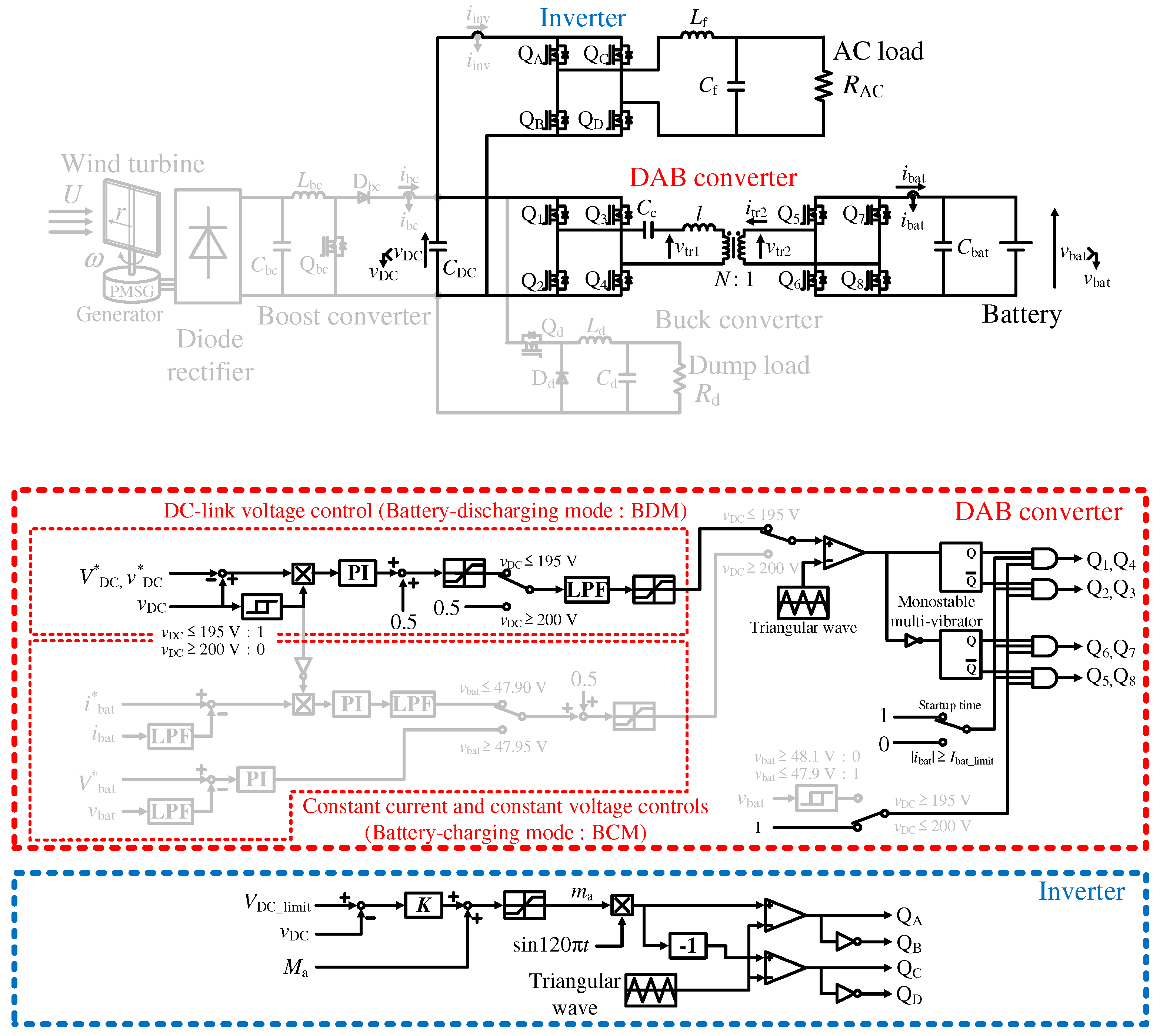
2. Standalone WPGS with DAB Converter
2.1. System Configuration
2.2. Variable Modulation Index Control of VSI
3. Proposed Variable DC-Link Voltage Control
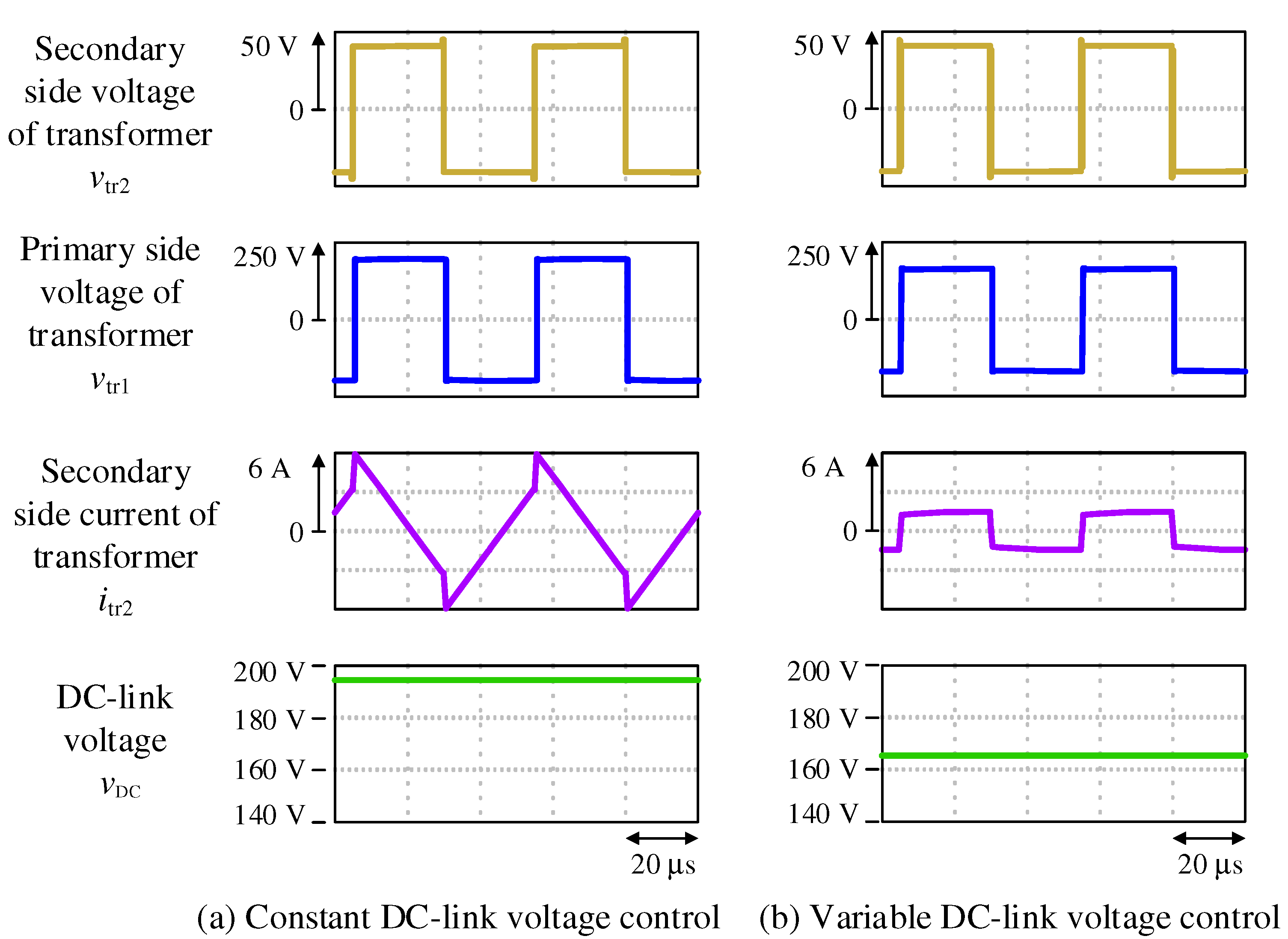
3.1. Conventional Constant DC-Link Voltage Control
- Conduction loss of switch and conducting wire
- Copper loss of transformer
- Loss by equivalent series resistor of capacitor
- Loss by back power flow
- Switching loss increased by failure of zero voltage switching (ZVS)
3.2. Proposed Variable DC-Link Voltage Control
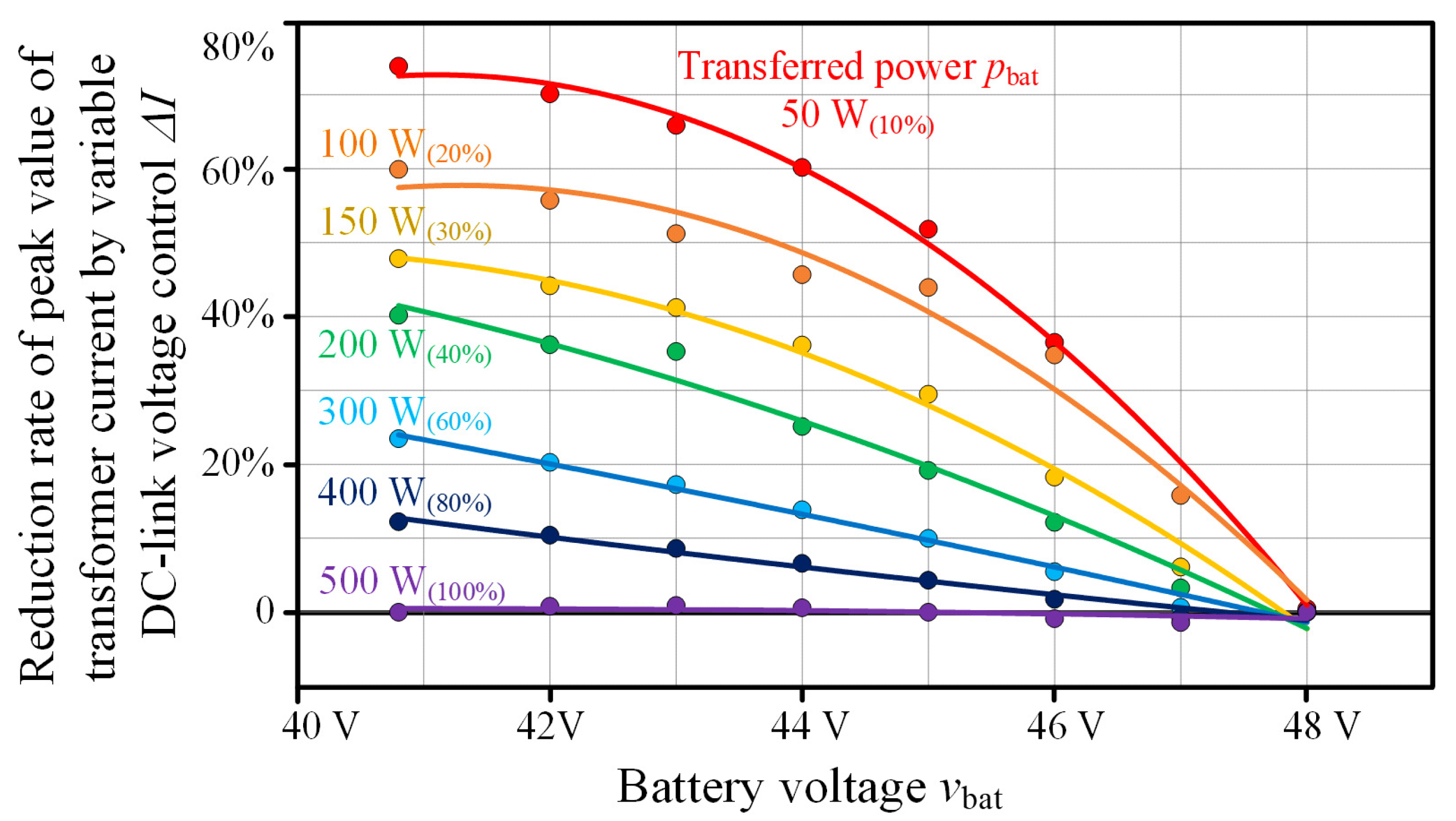
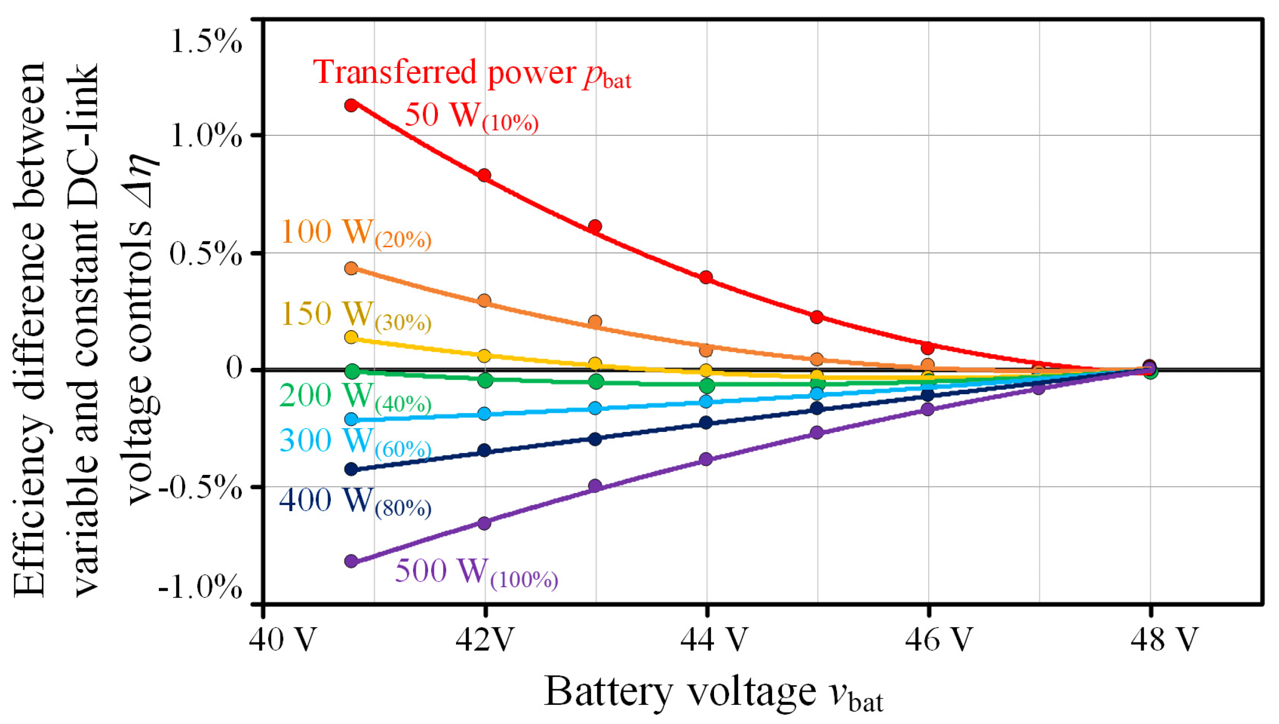
3.3. Comparison between Each Control Method
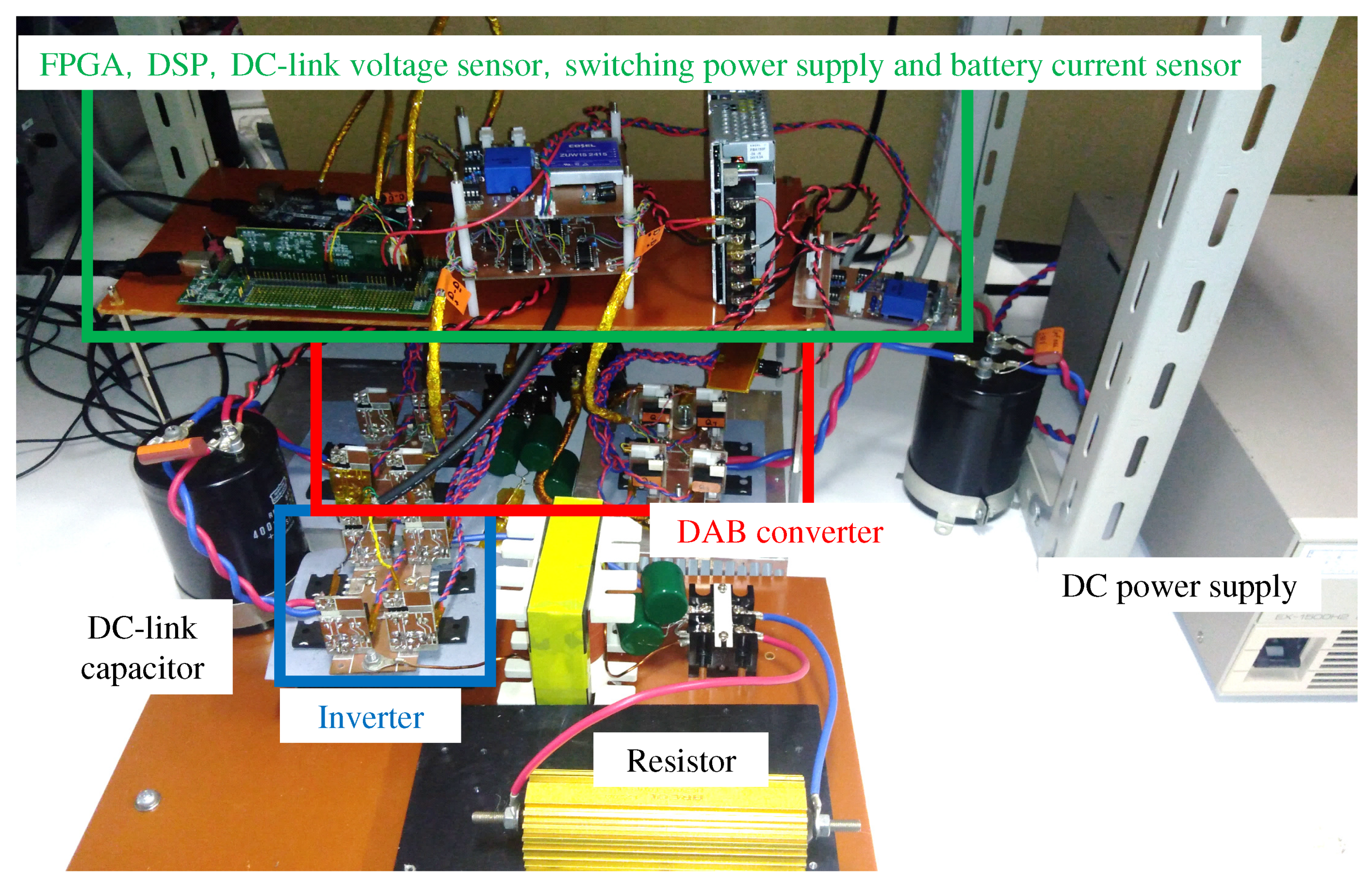
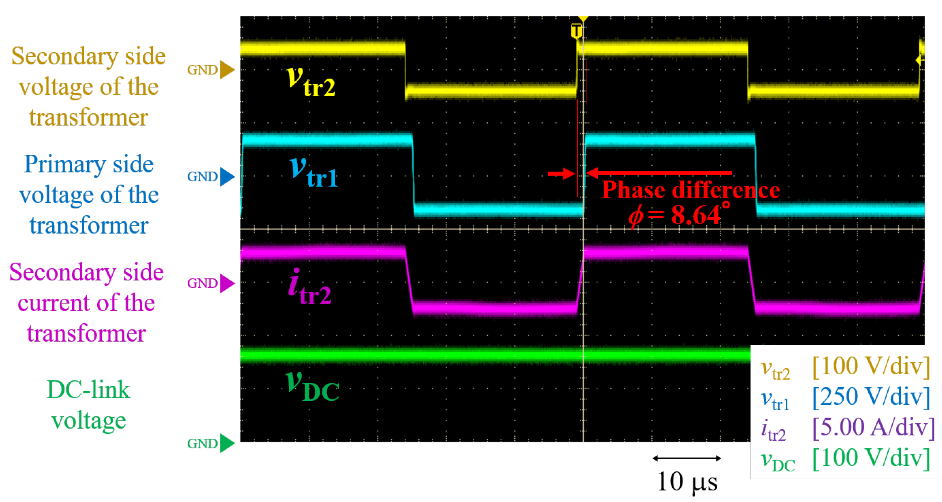
4. Experimental Verification of Variable DC-Link Voltage Control
5. Proposed Reference DC-link Voltage Switchover Control
6. Conclusions
Author Contributions
Funding
Acknowledgments
Conflicts of Interest
References
- Wu, Q.; Solanas, J.I.B.; Zhao, H.; Kocewiak, Ł.H. Wind Power Plant Voltage Control Optimization with Embedded Application of Wind Turbines and STATCOM. In Proceedings of the Asian Conference on Energy, Power and Transportation Electrification (ACEPT), Singapore, 25–27 October 2016; p. 16585658. [Google Scholar]
- Ge, W.; Chen, H.; Liu, Q.; Tan, H.; Shen, L.; Wang, S.; Ji, Y. Optimization of wind power grid connection in multi-source and multi-region power generation system based on peak adjustment margin. In Proceedings of the Ninth International Conference on Intelligent Control and Information Processing (ICICIP), Wanzhou, China, 9–11 November 2018; p. 18401969. [Google Scholar]
- Toledo, S.; Maqueda, E.; Rivera, M.; Gregor, R.; Wheeler, P.; Romero, C. Improved Predictive Control in Multi-Modular Matrix Converter for Six-Phase Generation Systems. Energies 2020, 13, 2660. [Google Scholar] [CrossRef]
- Huu, D.N. A Novel Adaptive Control Approach Based on Available Headroom of the VSC-HVDC for Enhancement of the AC Voltage Stability. Energies 2021, 14, 3222. [Google Scholar] [CrossRef]
- Saboori, H.; Jadid, S.; Savaghebi, M. Spatiotemporal and Power–Energy Scheduling of Mobile Battery Storage for Mitigating Wind and Solar Energy Curtailment in Distribution Networks. Energies 2021, 14, 4853. [Google Scholar] [CrossRef]
- Global Wind Energy Council, Global Wind Energy Outlook 2016. Available online: https://gwec.net/global-wind-energy-outlook-2016/ (accessed on 30 June 2019).
- Koutroulis, E.; Kalaitzakis, K. Design of a Maximum Power Tracking System for Wind-Energy-Conversion Applications. IEEE Trans. Ind. Electron. 2006, 53, 486–494. [Google Scholar] [CrossRef]
- Taniguchi, D.; Narisada, Y.; Yamada, H.; Tanaka, T.; Tamura, T.; Yamada, S.; Okamoto, M. Variable Tip Speed Ratio Control in a Stand-Alone Small-Scale Wind Power Generation System. J. Jpn. Inst. Power Electron. 2017, 43, 43–49. [Google Scholar] [CrossRef]
- Lachguer, N.; Lamchich, M.T. Control Strategy of Permanent Magnet Synchronous Generator for Stand Alone Wind Power Generation System. In Proceedings of the International Aegean Conference on Electrical Machines and Power Electronics and Electromotion, Istanbul, Turkey, 8–10 September 2011; pp. 392–397. [Google Scholar]
- Tian, C.; Zhang, C.; Li, K.; Chu, X.; Cui, N.; Wang, J. Control Strategy for Bi-Directional DC/DC Converter of a Stand-Alone Wind Power System. In Proceedings of the 3rd IEEE International Symposium on Power Electronics for Distributed Generation Systems, Aalborg, Denmark, 25–28 June 2012; pp. 297–300. [Google Scholar]
- Takayama, Y.; Yamada, H. Dual Active Bridge Converter Based Battery Charger in Stand-Alone Wind Power Generation System with High-Inertia Wind Turbine. In Proceedings of the 22nd International Conference on Electrical Machines and Systems (ICEMS2019), Harbin, China, 11–14 August 2019; p. 1570545226. [Google Scholar]
- Kheraluwala, M.N.; Gascoigne, R.W.; Divan, D.M.; Baumann, E.D. Performance Characterization of a High-Power Dual Active Bridge dc-to-dc Converter. IEEE Trans. Ind. Appl. 1992, 28, 1294–1301. [Google Scholar] [CrossRef]
- Xue, L.; Shen, Z.; Boroyevich, D.; Mattavelli, P.; Diaz, D. Dual Active Bridge-Based Battery Charger for Plug-In Hybrid Electric Vehicle with Charging Current Containing Low Frequency Ripple. IEEE Trans. Power Electron. 2015, 30, 7299–7307. [Google Scholar] [CrossRef] [Green Version]
- Yamanaka, H.; Yamada, H. Dual Active Bridge DC-DC Converter Based Wide Dimming Range LED Driver with High-Speed Turn-Off for High-Brightness LED Floodlight. IEEJ J. Ind. Appl. 2019, 8, 556–557. [Google Scholar] [CrossRef]
- Malek, M.H.A.B.A.; Kakigano, H.; Takaba, K. Dual Active Bridge DC-DC Converter with Tunable Dual Pulse-Width Modulation for Complete Zero Voltage Switching Operation. IEEJ Ind. Appl. 2019, 8, 98–107. [Google Scholar] [CrossRef] [Green Version]
- Ríos, S.J.; Pagano, D.J.; Lucas, K.E. Bidirectional Power Sharing for DC Microgrid Enabled by Dual Active Bridge DC-DC Converter. Energies 2021, 14, 404. [Google Scholar] [CrossRef]
- Gierczynski, M.; Grzesiak, L.M.; Kaszewski, A. A Dual Rising Edge Shift Algorithm for Eliminating the Transient DC-Bias Current in Transformer for a Dual Active Bridge Converter. Energies 2021, 14, 4264. [Google Scholar] [CrossRef]
- Baddipadiga, B.P.; Ferdowsi, M. Dual Loop Control for Eliminating DC-Bias in a DC-DC Dual Active Bridge Converter. In Proceedings of the International Conference on Renewable Energy Research and Application (ICRERA), Milwaukee, WI, USA, 19–22 October 2014; p. 14867746. [Google Scholar]
- Bhattacharjee, A.K.; Tayebi, S.M.; Batarseh, I. Fast Response Dual Active Bridge Converter with Elimination of Transient DC Offset by Intermediate Asymmetric Modulation. In Proceedings of the IEEE Energy Conversion Congress and Exposition (ECCE), Portland, OR, USA, 23–27 September 2018; p. 18307624. [Google Scholar]
- Takayama, Y.; Yamada, H. Power Loss Reduction by Stand-Alone Wind Power Generation System with Dual Active Bridge Converter Based Battery Charger. In Proceedings of the 21st IEEE Hiroshima section student symposium (HISS), Hiroshima, Japan, 30 September–1 October 2019; pp. 265–268. [Google Scholar]
- Takayama, Y.; Yamada, H. Experimental Verification of Dual Active Bridge Converter Based Battery Charger in a Stand-Alone Wind Power Generation System. In Proceedings of the 23rd International Conference on Electrical Machines and Systems (ICEMS2020), Online, 24–27 November 2020; pp. 1022–1026. [Google Scholar]
- Takeno, S. Electrical Regulation and Plant Maintenance; Tokyo Denki University Press: Tokyo, Japan, 2019. [Google Scholar]


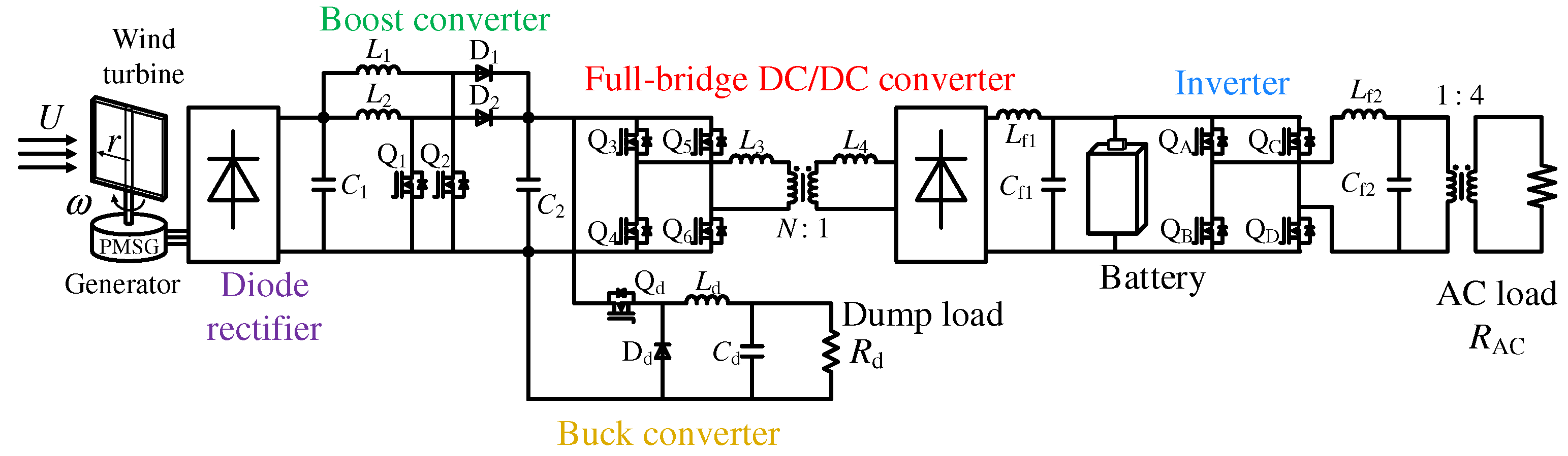
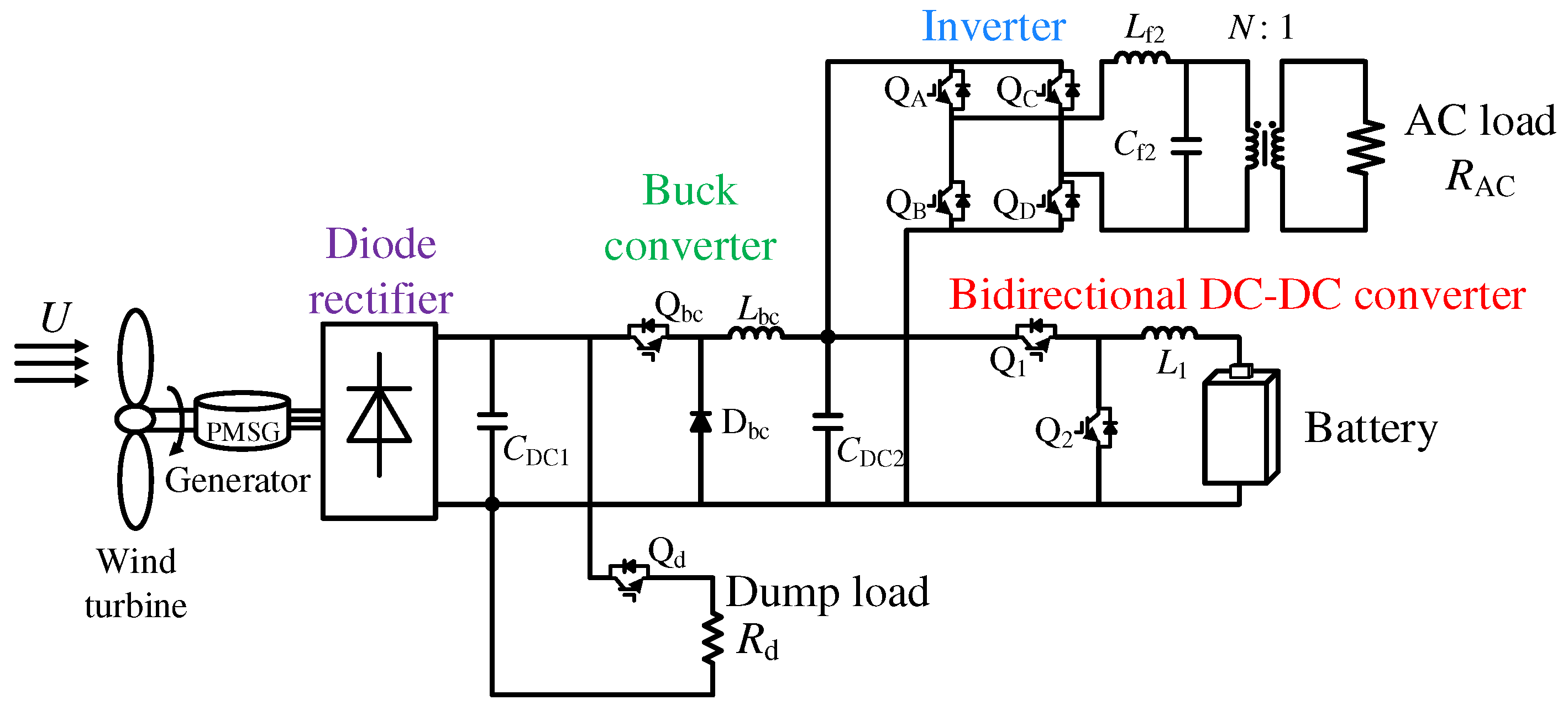
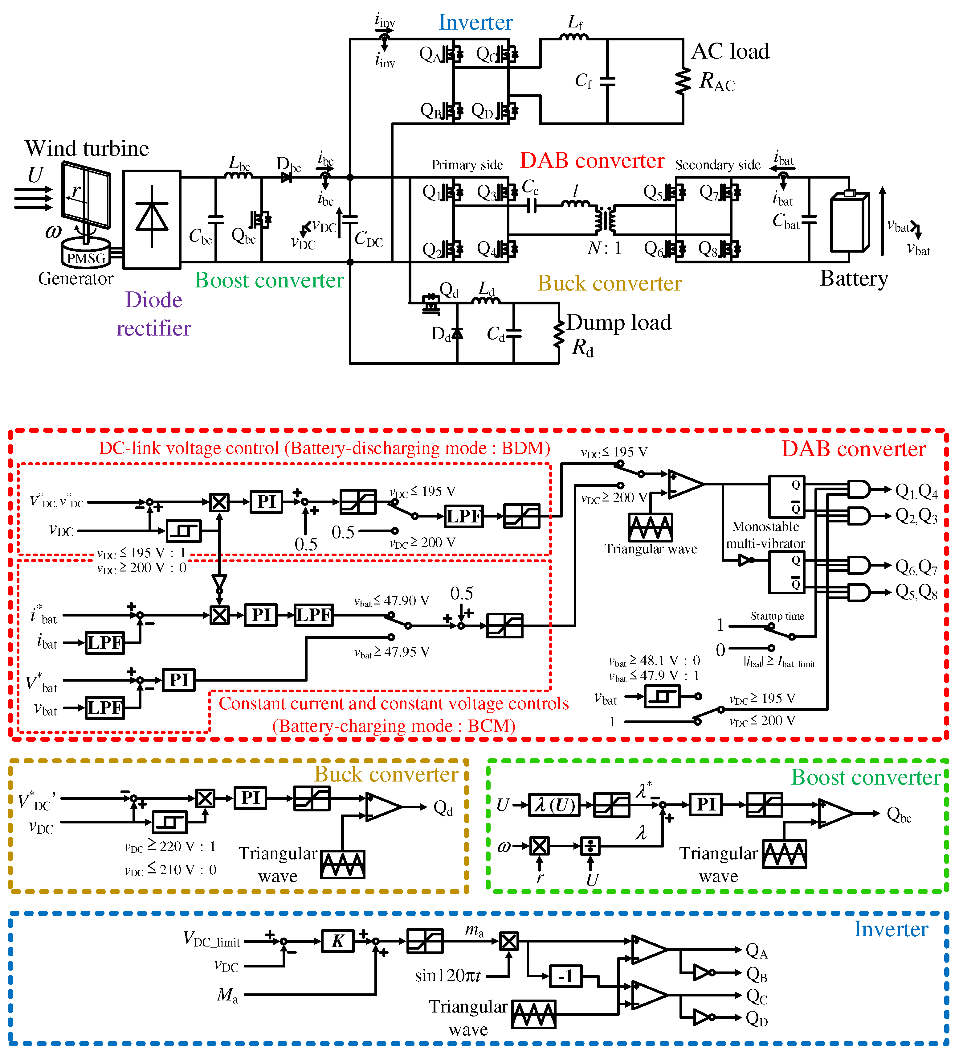
| Figure 1 | Figure 2 | Figure 3 | |
|---|---|---|---|
| Number of stage | 4 stages | 2 stages | 3 stages |
| Commercial transformer | Necessary | Not necessary | Necessary |
| Cell voltage equalizer | Not necessary | Necessary | Not necessary |
| Item | Symbol | Value |
|---|---|---|
| Battery voltage | 40.8 V to 48.0 V | |
| Resistance load | 20 to 200 | |
| Filter inductor | 984 H | |
| Smoothing capacitor | 4700 F | |
| DC-link capacitor | 4700 F | |
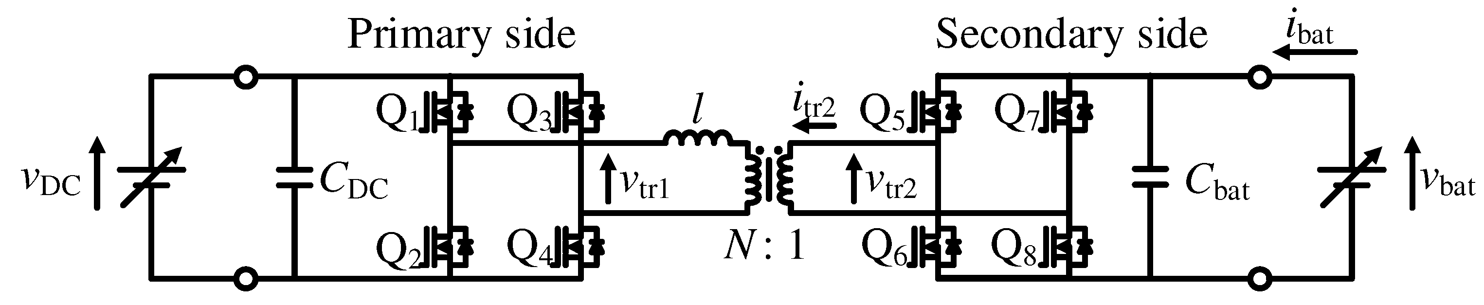
| Coupling capacitor | 3 F | |
| Filter capacitor | 6.52 F | |
| Turn ratio of transformer | 4:1 | |
| Leakage inductance of transformer | l | 320 H |
| Winding resistance of transformer | 123 m | |
| Exciting conductance of transformer | 1.38 mS | |
| Exciting susceptance of transformer | 8.13 mS | |
| Switching frequency | 20.0 kHz | |
| Cut-off frequency of LC filter | 1.99 kHz | |
| Dead time | 0.4 s |
Publisher’s Note: MDPI stays neutral with regard to jurisdictional claims in published maps and institutional affiliations. |
© 2021 by the authors. Licensee MDPI, Basel, Switzerland. This article is an open access article distributed under the terms and conditions of the Creative Commons Attribution (CC BY) license (https://creativecommons.org/licenses/by/4.0/).
Share and Cite
Takayama, Y.; Yamada, H. Variable DC-Link Voltage Control of Dual Active Bridge Converter in a Standalone Wind Power Generation System for High-Efficiency Battery-Discharging Operation. Energies 2021, 14, 6786. https://doi.org/10.3390/en14206786
Takayama Y, Yamada H. Variable DC-Link Voltage Control of Dual Active Bridge Converter in a Standalone Wind Power Generation System for High-Efficiency Battery-Discharging Operation. Energies. 2021; 14(20):6786. https://doi.org/10.3390/en14206786
Chicago/Turabian StyleTakayama, Yuto, and Hiroaki Yamada. 2021. "Variable DC-Link Voltage Control of Dual Active Bridge Converter in a Standalone Wind Power Generation System for High-Efficiency Battery-Discharging Operation" Energies 14, no. 20: 6786. https://doi.org/10.3390/en14206786
APA StyleTakayama, Y., & Yamada, H. (2021). Variable DC-Link Voltage Control of Dual Active Bridge Converter in a Standalone Wind Power Generation System for High-Efficiency Battery-Discharging Operation. Energies, 14(20), 6786. https://doi.org/10.3390/en14206786