Article

Investigations of the Usefulness of Dilatometric Methods in the Diagnostics of Combustion Engines

Institute of Combustion Engines and Powertrains, Poznan University of Technology, 61-138 Poznań, Poland
*
Author to whom correspondence should be addressed.
Energies 2021, 14(20), 6703; https://doi.org/10.3390/en14206703
Submission received: 23 August 2021 / Revised: 24 September 2021 / Accepted: 13 October 2021 / Published: 15 October 2021
(This article belongs to the Special Issue Optimization of IC Engines and Engines Combustion Systems)

Abstract

:
Due to rapidly progressing development in the field of materials used in the automotive industry, research methods enabling the validation of the properties of materials used in specific applications, e.g., engines, are gaining importance. One such method is dilatometry, which belongs to a branch of physics dealing with methods of measuring the thermal expansion of bodies. It includes assessment study of the dependence of body measurements on external conditions. The authors propose that dilatometric methods could be used to diagnose damage and the causes of engine damage that has already occurred. This is a novel approach in diagnostic methods. The aim of the paper was to validate the proposed method for diagnosing of combustion engine components. Two cases of malfunction of this type of device are presented. In the first case, the subject of research is needle-nozzle holder precision pairs used in engines with a power of 150 kW. The main achievement of the research is revealing the occurrence of different thermal expansion values of the materials in the individual nozzle holders, with specific needles in particular causing adverse changes in clearances between these elements. The other case involved tests with respect to engine pistons. The proposed test method allows for a very accurate and relatively quick determination of the degree of damage to their surface. The conducted research confirms the usefulness of dilatometric methods in diagnosing combustion engines—their application makes it possible to determine the causes for the formation of the irregularities. The presented results are promising and enable further development of the methods and their implementation not exclusively with regard to internal combustion engines.

1. Introduction

The primary way of diagnosing the operation of modern combustion engines is through the use of an on-board diagnostic (OBD) system. Components of this system are used in many areas of internal combustion engine operation. These include misfire monitoring [1,2], diesel particulate filter monitoring [3,4,5,6], catalyst monitoring [7,8], fuel system monitoring [9,10], and EGR system monitoring [11,12,13]. The common features of these systems are that they supervise the operation of the electronic control systems, and that their operation aims to control engine operation in order to meet ecological requirements. These systems are standard equipment in passenger vehicles. However, there are some defects, the occurrence of which does not trigger a response in the diagnostic system. Examples of this type of damage include misalignment of valve timing, wear of cylinder bore, increasing wear of valve seats, and wear of injector nozzles. Such mechanical faults and operational wear, especially in the early stages, are compensated for by adaptive control systems as a result of the accepted permissible control ranges. It is only after a major malfunction has occurred that the course of the control process is so disturbed that it is relatively easy to find the fault, because the system switches to emergency operation. Changes in the technical condition of the engine, caused by the early stages of its wear, are difficult to detect. Vibroacoustic methods are applicable in this respect [14]. The situation is slightly different when it comes to diagnosing the causes of already existing damage to internal combustion engine components. In this respect, one popular method is endoscopy (using fiber optics) [15,16]. Oil wear testing and spectroscopic analysis of wear products (especially metals) accumulated in oil and filters are also used to diagnose the cause of damage. The authors of the article propose the addition of dilatometric methods to the methods mentioned regarding the diagnosis of faults and the causes of faults.
Dilatometry is a branch of physics dealing with methods of measurement of the thermal expansion of bodies. It also deals with the dependence of the object dimensions on external conditions. The main tool for the measurement of thermal expansion is the dilatometer. The term thermal expansion refers to changes in the linear (linear thermal expansion) and volumetric (volumetric thermal expansion) dimensions of bodies following temperature changes. In numbers, the thermal expansion can be described with Formula (1):
x(T) = x(T0){1 + α(T − T0)}
where:
  • x(T)—dimensions of an object in temperature T,
  • x(T0)—dimensions of an object in the initial temperature,
  • α—coefficient of thermal expansion (for most of the substances it is α > 0, but for water the value α depends on the temperature; in particular, in the range from 0 °C to 4 °C, it has negative values).
For crystalline objects, the thermal expansion can be different in different directions. When that is the case, the coefficient of thermal expansion becomes a tensor. The fundamental factors in classifying tensors are the transformation principle during the modification of the reference system and its order (the number of indicators necessary for its characterization). Tensors of the first order are represented by one-dimensional objects—one-column or one-row tables—tensors of the second order by two-dimensional tables, etc. If a change in the reference system does not lead to a change in the tensors, it is scalar or invariant (invariance). A contravariant vector (pursuant to the convention, it has its index at the top) is a tensor of the first order subject to the following principle of transformation (2).
ai’ = Σ(∂xi’/∂xi)ai
(Symbols containing the ‘prime’ indicate a new reference system.) Tensors of higher orders are defined analogically: covariant, contravariant, and mixed, i.e., having parts of the covariant and contravariant components, hence having parts of the indexes in the superscript and parts in the subscript [17]. The valence of the tensor is a pair of numbers (n, m), the first of which determines the number of contravariant components and the second the number of covariant components, e.g., the law of transformation of mixed tensors R of valence (1,2) has the following form (3):
Ri’j’k’ = (∂xi’/∂xi)(∂xj/∂xj’)(∂xk/∂xk’)Rijk
The multi-level nature of dilatometric analysis and the use of such methods for various analytical tasks related to the characteristics of materials have led tools based on this type of method to be successfully used in widely understood materials science [18,19,20,21,22,23,24]. Additionally, the ease of use and the mostly simple geometry of the sample make dilatometry a productive tool for thermophysical materials testing.
Dilatometric methods can be used in the area of combustion engines; however, as can be seen from the literature analysis, their use in this area is still not widespread, and does not address the search for the cause of engine component failures. These methods are most often used to determine the thermal expansion coefficients of selected components of combustion engines [25]. In research conducted by Anand and Parthasarathy [26], dilatometry has been used, among other things, in the analysis of thermal expansion of crankshafts subjected to nitriding. Another example is the research [27,28] conducted by Jankowski, Siemińska et al., consisting, inter alia, of analyzing the influence of various alloy additions on changes in the linear expansion coefficient of engine pistons. The researchers proposed a new material for pistons, which is an aluminum alloy containing unconventional alloying elements—molybdenum, cobalt, and chromium. In this case, the use of dilatometric methods confirmed the improvement in the strength of the material, and above all the improvement in the dimensional stability of the tested elements. Similarly, dilatometric methods were used in the studies of Zebarjad and Sajjadi. The authors of the research presented in [29] analyzed the possibility of using metal composites (MMCs) in automotive applications (brake discs), including engine applications (pistons). They carried out a series of analyses (microhardness test, compression test, wear resistance test), during which dilatometric measurements were made. In [30], the authors also used dilatometric analysis—the conducted research concerned the evaluation of the properties of the eutectic Al-Si alloy used in the production of cast pistons of combustion engines. Measurements made with the use of a dilatometer justified, among other things, the necessity of applying heat treatment to the tested pistons in order to stabilize the material structure. The use of such prepared pistons confirmed the elimination of significant structural changes in the material, which may lead to deterioration of the mechanical properties of the element.
On the other hand, in [31], the authors paid special attention to the contribution of metrology to the research and development of thermophysical properties of materials used in the automotive industry. The use of advanced materials with specific thermal properties is currently one of the areas of activity being intensively developed in broadly understood industry. It has been proven that the accurate measurement of the thermophysical properties of materials is of particular importance in the rapidly developing automotive industry. Application of, among other things, dilatometric methods to determine the coefficient of thermal expansion allows the validation of the correct use of new materials in specific applications, such as, for example, exhaust aftertreatment systems or the exhaust systems of piston engines.
The analysis of the global state of knowledge relating to the use of dilatometric methods in engine applications shows that their application focuses on checking, under conditions of variable operating temperatures, the behavior of materials. To the best of the authors’ knowledge, there are no examples of the use of dilatometric methods to diagnose abnormalities in the operation of components already used in specific engine solutions. Obtaining precise information about the condition of a component enables a detailed understanding of the impact of the nature of its operation on the material out of which it is made.
Therefore, the aim of this work was to practically check the use of dilatometric methods to diagnose damage to selected components of combustion engines. The article presents two such cases. The first one, concerning the stability of precision injector pairs, has not been previously described in the literature. The second concerns damage to the pistons of internal combustion engines. The common characteristic of both of these cases are abnormalities in the operation of internal combustion engines—the use of dilatometric methods makes it possible to determine the cause of such occurrences. The originality of the research work carried supplements the global use of innovative devices with high measurement precision.

2. Materials and Methods

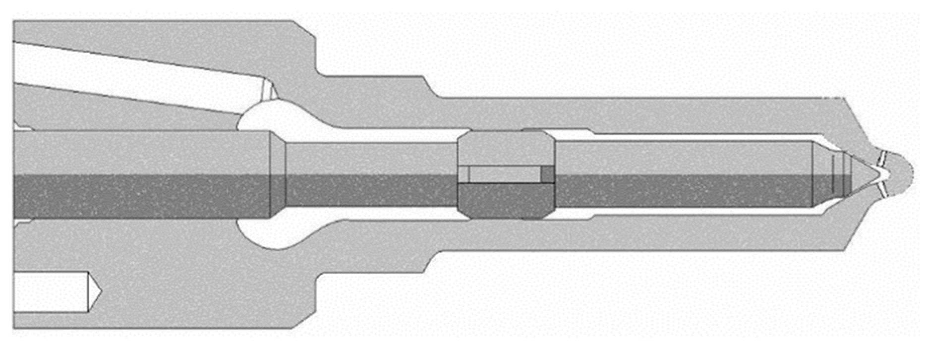
2.1. Injector Precision Pairs

The quality of the operation of diesel fuel injectors depends heavily on whether the problem of injector needle hanging is eliminated or at least reduced. Several factors that facilitate the occurrence of this phenomenon are [32,33,34]:
  • Selection of the materials used for the needle-nozzle holder pair,
  • Size and nature of deformations of the nozzle holder caused by pressure and temperature,
  • Quality of surface processing of the elements of the precision pairs,
  • Accuracy of the shape of the hole in the nozzle holder and the guiding part of the needle in the cross section and axial cross section of the injector,
  • Play between the needle and the nozzle holder, that, on one hand, should ensure free operation when different fuels are applied, while, on the other, preventing excessive fuel leakage,
  • Porosity and geometrical structure of the guiding surfaces of the needle and the nozzle holder,
  • Spring force exerted on the needle,
  • Size of the micro deformations of the nozzle holder when the injector nut is tightened.
In most cases, the selected materials fulfill the basic requirements, assuming that the thermal and thermal chemical processing were carried out properly. Materials used for the production of nozzle holders and needles require complex thermal processing aiming at completing the transformation process of residual austenite into martensite [35]. The temperature ranges of the individual operations are very narrow and require the use of furnaces with precise temperature adjusters [36]. Small temperature deviations in the thermal processing may result in a large amount of residual austenite that, during the operation of the injectors in elevated temperatures (175–250 °C), will transform into martensite [37,38,39]. Since martensite has a greater volume than austenite, linear dimensions and dilatometric properties of the material will be changed. This may lead to a reduction of the operating play and additionally facilitate needle jamming. The above phenomenon should also be analyzed with respect to in-operation elastic deformations of the nozzle holder caused by high-pressure and variable thermal stresses. These deformations may result in further reduction of the play between the needle and the nozzle holder, leading to mechanical jamming of the needle in extreme cases [40].
The influence of dilatometric changes of material properties on injector performance was studied on precise needle-injector pairs used for engines with power of 150 kW. The needles of these injectors were made from 15 HN steel and the nozzle holders from spheroid cast iron.
The aim of the investigation was:
  • Determination of the coefficients of linear expansion of needle and nozzle holder materials,
  • Determination (on the basis of dilatometric tests) of the temperature range of the process of transformation of residual austenite in the needles.
The tests were conducted on a modified LS4 type induction dilatometer operating on the direct measurement principle. This dilatometer was originally an optical dilatometer. For research purposes, this dilatometer was modified—the modification concerned the measuring head, furnace heating rate programmer and method of registration. Instead of the optical head, allowing magnification of 200–600 times, a head with an inductive sensor of Bimetr-1 type (VIS production) was used, allowing 100 times higher magnification. The simple cam-type programmer for heating the furnace was replaced with an electronic programmer with feedback, made by Wilmer. Instead of a photographic recorder, a Japanese-made potentiometric three-channel recorder of Rikadenki type was used, working in the X1, X2, X3 time system. On one channel (X1), elongation was recorded; on the other channel (X2), temperature changes were recorded. This resulted in two curves recorded side by side as a function of time. On the basis of the curves of the changes in the length recorded at a magnification of 2500 times and changes in the temperature measured with a NiCr-Ni thermocouple, the coefficient of linear thermal expansion was calculated on the basis of Relation (4):
α ¯ = l l 0 1 T
where:
  • l —change in the length,
  • l 0 —initial length of the sample for the measured temperature range,
  • T —temperature difference.
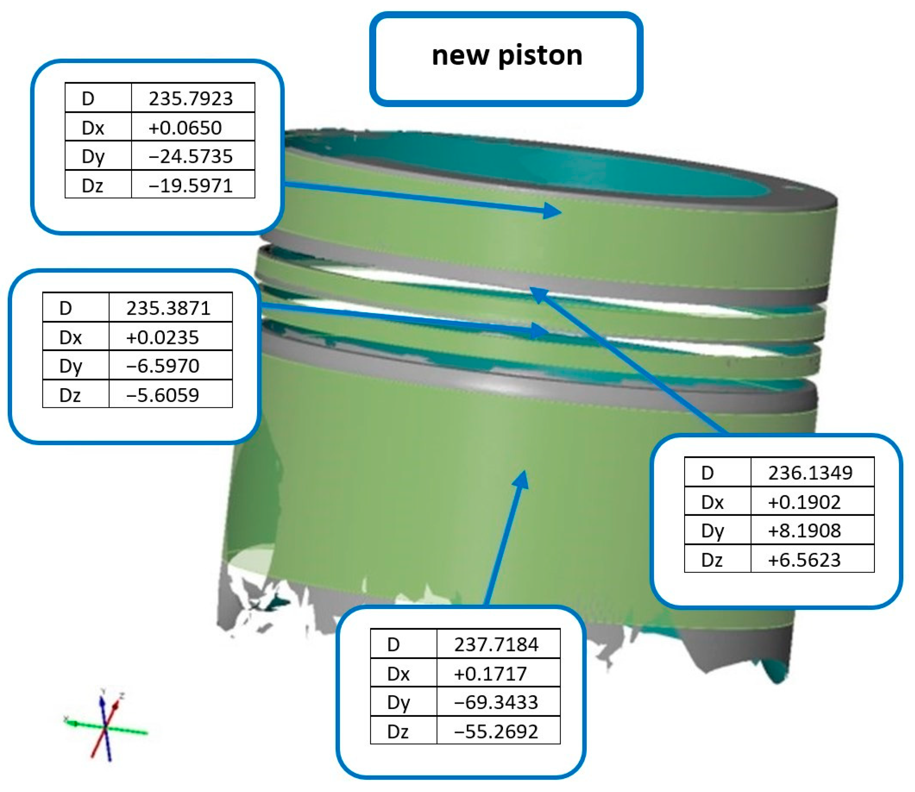
For the temperature changes, the authors used electronic compensation of the cold terminals of the thermocouple. The injectors were heated to a temperature of about 250 °C—the heating rate during the experiments was 2.5 °C/min. Eight new injectors of the same type were used in the study. A model of the nozzle geometry that was tested is shown in Figure 1. The samples cut out from the needles and nozzle holders were numbered according to their pairing in the precision pairs.
To determine the correctness of the factory thermal processing two needles, upon testing in a dilatometer, were again subjected to thermal processing. These needles were hardened and tempered according to the manufacturer’s technical documentation.

2.2. Pistons

The investigations were performed on a V-16 Waukesha P9390GL gas engine. The engine failed and stopped permanently. The tested piston had shiny spots on its skirt. The shiny spots were located on the level of the kingpin bore and under the lower ring (Figure 2). The described traces were more intense on the side on which the piston leans in the piston sleeve. In addition, in this part of the piston, there was more carbon fouling on the piston crown. The liner of the cylinder sleeve in contact with the piston had small scratches, no different from the effect of a properly operating piston [41].
The measurements, the tests and the analysis consisted of:
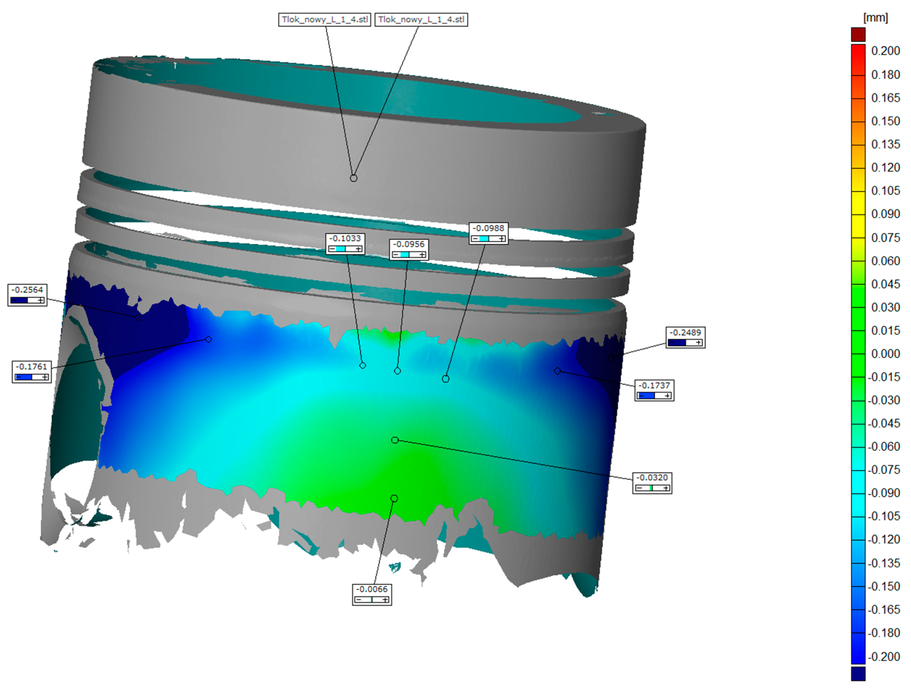
  • Measuring the geometry of the new and the worn piston using ATOS II optical coordinate scanner in the temperature of 21 °C,
  • Heating of new and worn pistons in a heat treatment furnace,
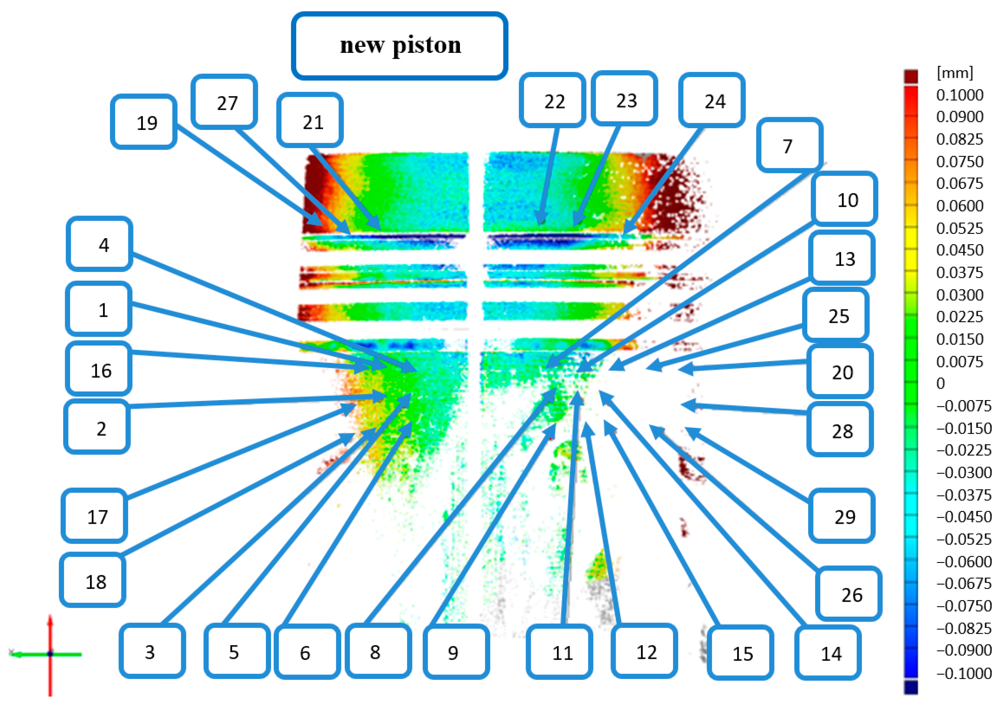
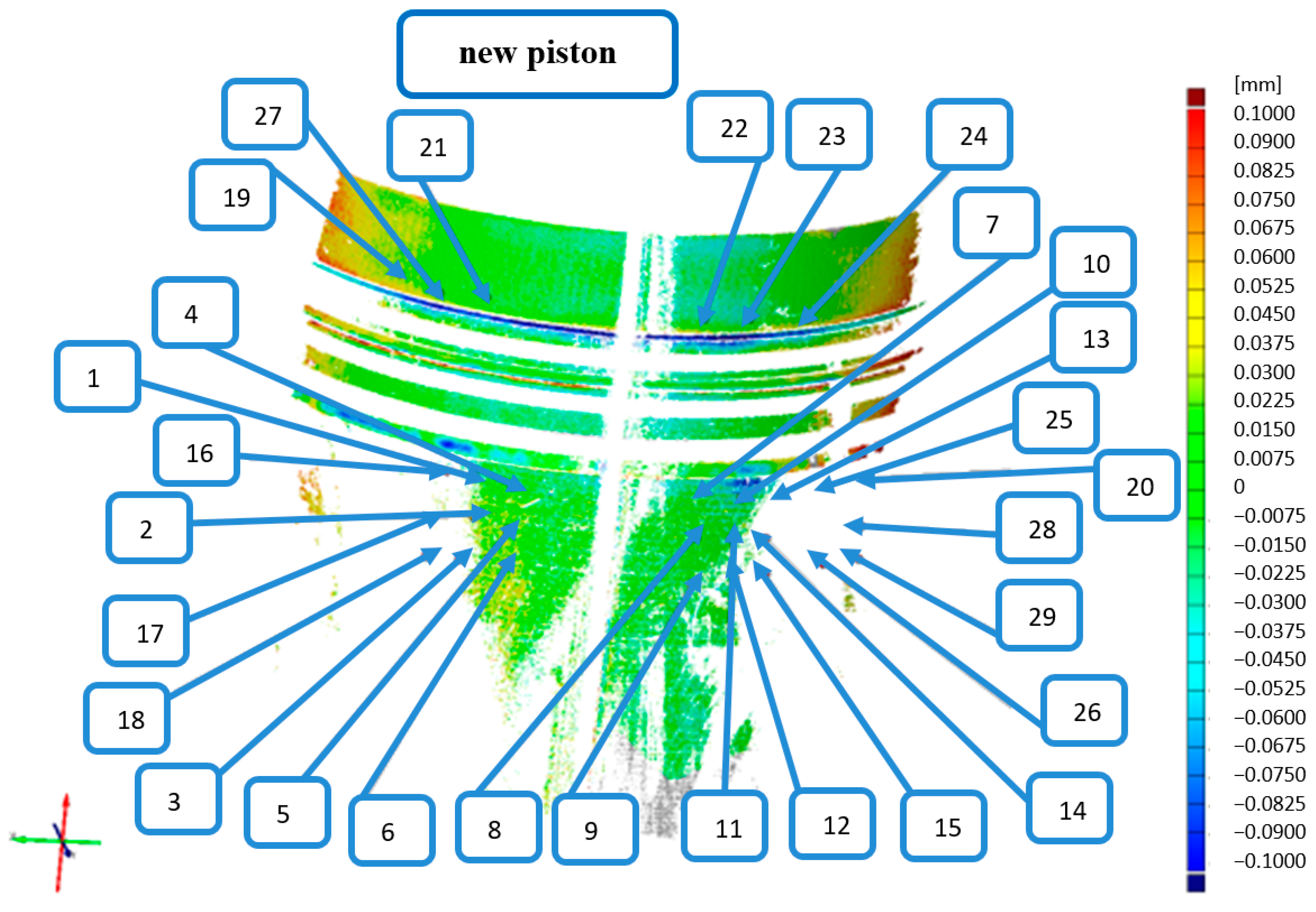
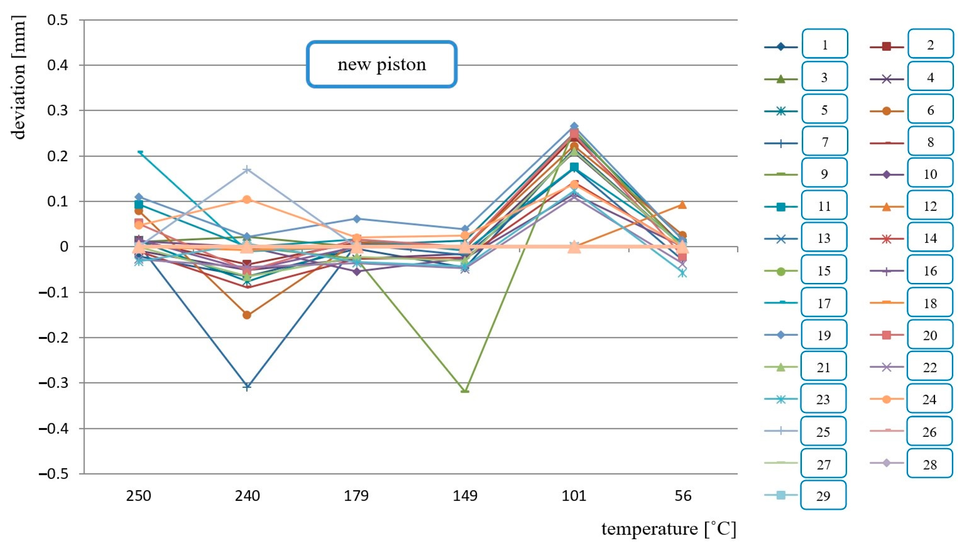
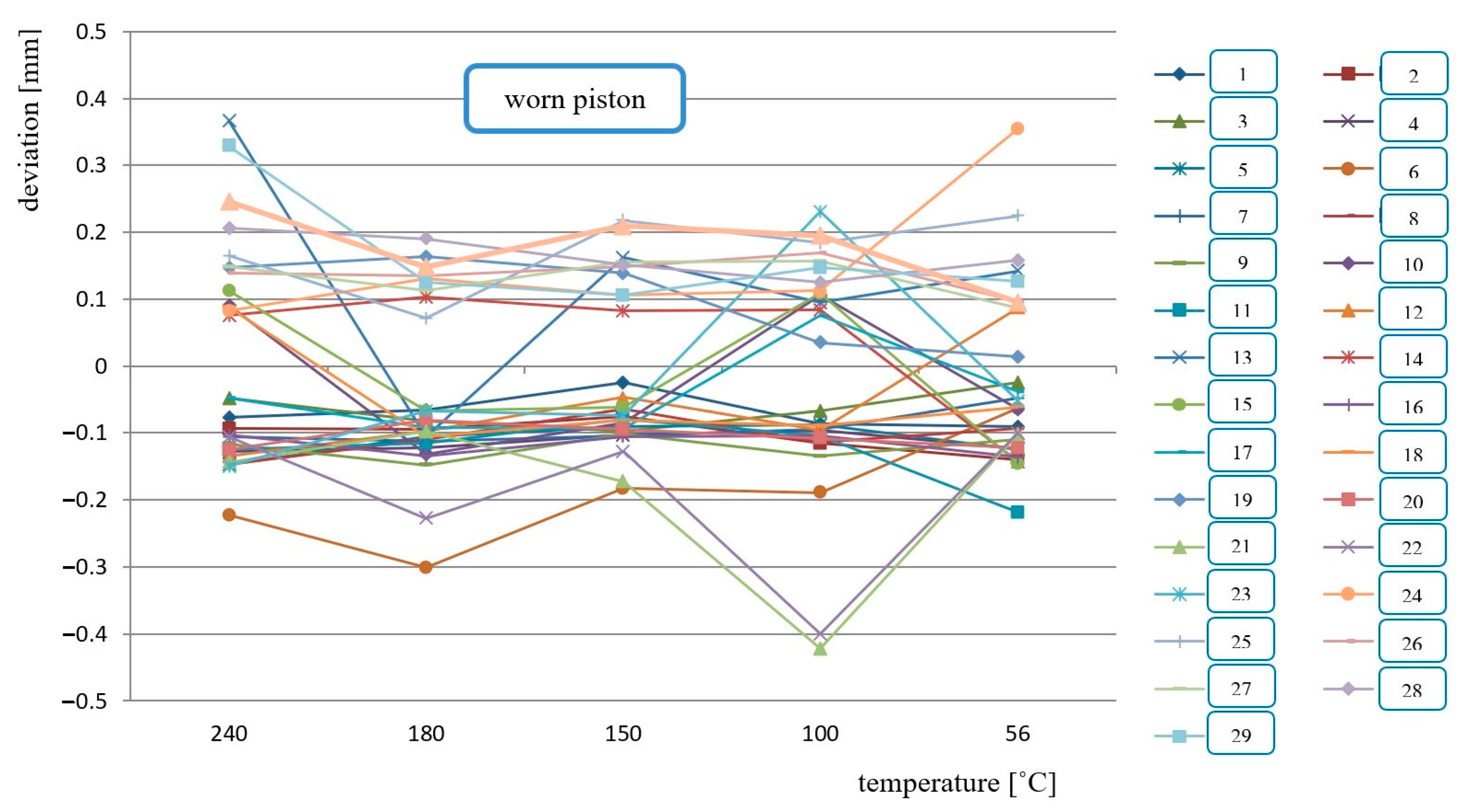
  • Measuring the geometry of the pistons with the optical coordinate scanner during cooling from the temperature from 240 °C (worn piston) and from 250 °C (new piston),
  • Analysis of the results of the piston geometry measurements,
  • Comparative examination of the pistons,
  • Analysis of the results of geometrical measurements during the cooling process.
In the proposed piston testing method, a highly sophisticated ATOS II measurement system by GOM was applied. The system has a projector and two digital cameras providing 1.4 million measurement points. The measurement range is 175 × 140 to 2000 × 1600 mm2 [42]. The application of a special type of lens and high-quality projector ensures very high resolution of the cluster of points, while eliminating most of the static when testing objects of the dimensions of up to 2000 mm [42,43,44].
The measurement consists of the projection of stripes with white light and their being recorded by the two cameras. The system then determines the position of the sensor and analyzes the value of the measurement points in a coordinate system of the measured object. The result of the measurement with the ATOS scanner is the spatial presentation of surface in the form of a cluster of points having a common coordinate system. The system compares the data pulled from the measured object with the CAD model. The results can be presented in the form of maps with deviations from the CAD model or in the form of tables.

3. Results and Discussion

3.1. Injector Precision Pairs

During the tests, a wide spread of thermal expansion was recorded in the needles. To determine the consequences of such a spread, graphs depicting the play of the needle-nozzle holder were developed for each of the individual precision pairs, depending on the operating temperature (Figures 3–8). The reference play marked in the graphs is the correct (i.e., prescribed by the designer) value, and remains unchanged during operation. This play under actual operating conditions at temperatures ~150–200 °C may be reduced by up to 50% (injector 7—Figure 3). These are very significant differences. A small increase in play is not disadvantageous (it is very common for this play to be reduced as a result of micro deformations in the nozzle holder), but its reduction following non-uniform thermal expansion of the operating components is very dangerous.
The determination of different thermal expansion values in the materials of the individual nozzle holders and needles, leading to adverse changes in the play between these components, is the main achievement of the present investigation. The reason for this phenomenon is the difference in the structure of the tested materials.
The graphs of the play values as a function of temperature indicate the presence of austenite in the tested needles (increase in the extension in the temperature range of ~200–300 °C). On the basis of the conducted tests, it can be confirmed that the differences in the austenite content are significant. These differences may have been caused by different structures in the carbonitrided layer or different structures forming during thermal processing. The influence of the non-uniformity of the structure of the material of which the needles are made on the dilatation changes is usually miniscule. In terms of changes in the dimensions of the components of precision pairs, thermal and thermal–chemical processing are decisive. Therefore, in order to explore this phenomenon, in the first place, one should check the structure after thermal processing and then check the structure and chemical composition of the material from which the needle was made.
To prove that the stability of the dimensions can be influenced by imprecisely conducted thermal treatment, needles 7 and 8 (Figure 3 and Figure 4) were subjected to thermal processing once more. The thermal treatment consisted of vacuum quenching using a vacuum furnace with high-pressure gas cooling. A significant improvement in the stability of the dimensions was achieved.
The presence of residual austenite in the material structure of the needle is very unfortunate, because austenite is prone to transformation into martensite at higher temperatures (for long heating times from approximately 150 °C). It is widely known that martensite has greater volume. An increase in the volume results in a reduction of the play in the precision pair, and may lead to jamming of the needle. Therefore, in order to verify whether it is possible to fully eliminate residual austenite from the needle, needle 4 was additionally tempered at a temperature of about 200 °C. After this tempering, a small drop in hardness was observed to approximately 730 HV, and no residual austenite was observed during dilatometric tests. The coefficient of linear expansion of this sample was the lowest (Figure 5). The results of the attempt to eliminate the residual austenite in the needles indicate that the method is effective.
The results obtained prove that monitoring the thermal expansion of materials as early as at the production stage makes it possible to check their quality—this is extremely important, considering the materials from which precision pairs of needle are made. This fact is illustrated in Figure 6, Figure 7 and Figure 8, which show the variation of the degree of play in precision pairs as a function of operating temperature. These diagrams indicate that the dilatation properties of the precision pairs must also be taken into account when selecting materials for precision pairs.

3.2. Pistons

The processing algorithm in the proposed method is based on two basic measurement stages. In the first stage, geometrical tests are conducted at a reference temperature of 21 °C. In the second stage, the geometrical tests are conducted during the cooling process of the hot pistons. The tests include the determination of the average diameters of the piston grades and the actual deviations at the inspection points. The algorithms used to calculate the replacement components were based on the adjoining elements, i.e., the minimum cylinder described for all measurement points (Figure 9 and Figure 10, Table 1).
The diameters were measured at four different circumferences, as shown in Figure 9—the differences in the dimensions of the individual piston circumferences are shown in Table 1. The base dimensions correspond to the average values of a new piston.
As mentioned previously, this investigation focuses on the analysis of deviations at the inspection points on the pistons. On the basis of the geometric tests conducted at the reference temperature of 21 °C, it can be concluded that the diameter of the new piston is smaller than the diameter of the worn one, with greater values of the deviation with respect to ovalness at the guiding circumference of the piston. The analysis of deviations at the individual inspection points calculated on the basis of all measurement points for replacement cylinders according to the algorithm of the element described (i.e., the smallest described cylinder) for each piston separately, also indicates that the circumference of the worn piston is greater in diameter. This difference of 0.0725 mm may have a significant impact on the operation of the piston. This is confirmed by the comparison of the above values with the assembling clearance of the piston. Assuming that the clearance should theoretically be approximately 0.5–0.8‰ [45] of the diameter (238 mm), we can consider this value to be equal to 0.142 mm.
Another stage of the proposed method of piston testing is thermal investigations analyzing deviations at the measurement points of the pistons during the cooling process. The worn piston was cooled from 240 °C and the new one from 250 °C, as a result of the heating technique.
The authors encountered a certain difficulty, which was not directly related to the measurement method. The problem was the determination of the temperature of the guiding surface of the piston under regular operating conditions. This was related to the lack of information on the chemical composition of the aluminum alloy. The exhaust gas temperature of the engine where the pistons were installed at the external temperature of 5 °C was approximately 460 °C. It is generally known that the temperature of the piston surface will be lower. On the basis of a literature analysis [46], the authors determined that for pistons of similar dimensions and designations, the maximum temperature might fall in the range of 230–280 °C. Hence, the values set forth in the introduction of this paper were adopted. Further support for this choice was provided by the ignition temperature of the lubricant (Mobil Pegasus 710)—249 °C—used during the piston operation [47].
The deformations of the new piston at a temperatures of 250 °C and 56 °C are shown in Figure 11 and Figure 12, respectively. Example measurement results of the deformation of the new and the worn piston are provided in Table 2 and Table 3.
Using the described method, on the basis of the obtained results, it is possible to draw the following conclusions:
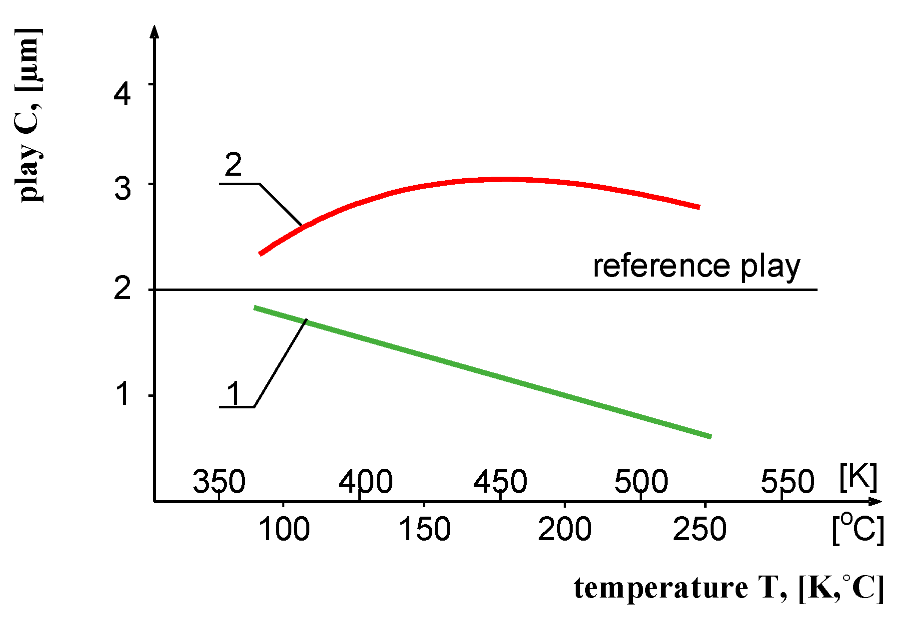
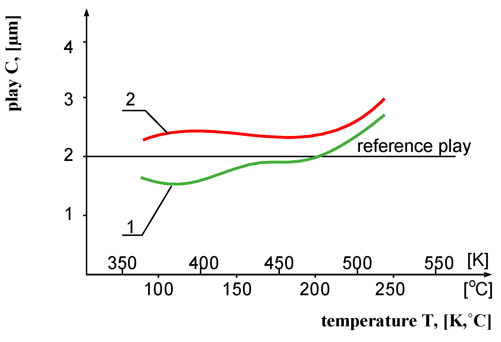
  • Cylinders described at inspection point 1 for the new piston and the worn one are oval,
  • Cylinder 1 had a greater diameter for the worn piston than the new one on the basis of the algorithm for the described element (i.e., the smallest described cylinder),
  • The deviation of the individual inspection points with respect to the replacement element confirms the greater diameter of the worn piston,
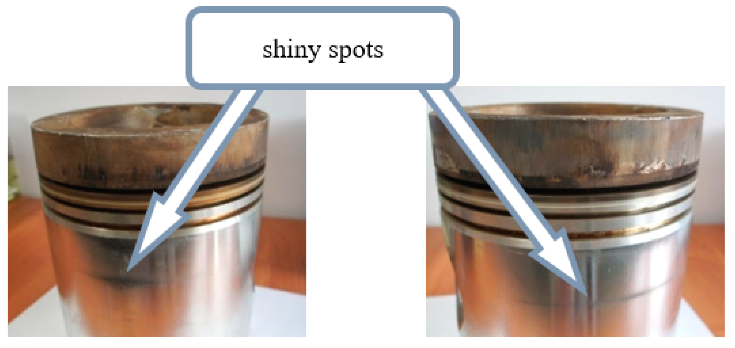
  • The analysis and tests were performed on a worn piston bearing traces of seizure, potentially confirming that the nominal diameter was greater than that measured (material scratches due to seizure).
On the basis of these measurements, it is possible to determine characteristics, as shown in Figure 13 and Figure 14.
By taking into account the change of temperature of the pistons for different measurement points, it was possible to determine the deviations. The reference measurement in this case was the measurement at the room temperature (21 °C). The obtained graphs show the effectiveness of the method used—a great spread of deviations with respect to the reference measurement (at the temperature of 21 °C) can be observed at the individual measurement points of the worn piston.
The analysis based on the geometrical test results obtained during the cooling process makes it possible to draw the following conclusions. In the combustion chamber cylinder zone, the spread of deformations is smaller and more stable for the new piston—a characteristic peak can be observed at the temperature of 100 °C. For the worn piston, the deformations at the individual measurement points are divergent, which may have been caused by the behavior of the material (deformations) when subjected to high temperatures—the material swells and shrinks unevenly in terms of both volume and area. Additionally, in the cylinder zone with the deformation, different distributions of deviations can be observed for the new and the worn pistons during cooling. For the new piston, the spread of deformations of the individual points has a rather stable distribution and the characteristic peak at the temperature of 100 °C. For the worn piston, this distribution of deviations is unstable—they are scattered around the individual measurement points located in the same piston areas—and the characteristic peak at the temperature of 100 °C cannot be observed. During cooling, the worn piston shows deviations with greater positive values than those obtained for the new piston. The occurrence of significant deviation values is related to the cause of engine damage, confirming the effectiveness of the proposed diagnostic method.

4. Conclusions

The authors of this paper proposed the addition of a method based on dilatometric measurements to the diagnostic methods used in the area of combustion engines. This method was validated using two different cases. In the first one, the stability of precision pairs of new injectors was tested. In the second case, this method allowed the diagnosis of the causes of engine piston failures. Both cases should be seen as novel approaches with respect to combustion engine diagnostics.
In the first case, the use of the method showed a large scatter of the materials’ thermal expansion in individual nozzle elements (needle holder and needles). Thanks to dilatometric tests, the occurrence of unfavorable changes in the plays between these elements was demonstrated, constituting the main achievement of this research and confirming the effectiveness of the proposed method. Therefore, this method is an effective way of testing the stability of injector precision pairs, particularly with the aim of performing proper material selection and processing. Checking the thermal expansion of materials in the final stage of production enables the verification of their quality as well as the quality of their processing. This is very well depicted in the graphs, which show the variability of the play in the precision pairs to be dependent on the operating temperature and indicate the need to allow for material dilatation properties when selecting materials for precision pairs. A disadvantage of dilatometric methods in the first case described is their destructive character. However, with correspondingly large production, it is possible to develop a non-destructive method to investigate injector precision pairs.
In the second case analyzed, the proposed research method allowed for a very precise and relatively quick determination of the degree of damage sustained by the surface of the engine pistons. The measurement method showed the presence of significant deviations from the reference measurements. These deviations, visible in the case of the worn piston, confirm this problem, which should also be considered the cause of the failure. In this particular case, the probable cause of engine failure could have been the use of unsuitable pistons. This could be related, for instance, to the use of an inappropriate aluminum alloy or to the inadequacy of the piston material to the operating conditions of the engine (gas engine). The cause of the failure could also have been related to the piston design, e.g., there was a significant accumulation of material in the area of the observed shine on the piston, which was also confirmed by the measurements carried out.
On the basis of the presented example measurements, the positive effects of applying this method are demonstrated. An obvious advantage of this method is the possibility of determining the reasons for engine malfunctions on the basis of the test results. It is necessary to note that the piston itself is rarely the primary reason for engine damage, but the first symptoms of damage to engine components are visible on this element. A disadvantage of this method is the necessity of using a reference piston. The best solution is to use a new piston, which constitutes a nominal reference for the conducted measurements, on the basis of which it is possible to compare the two pistons and consequently draw conclusions.
The presented results, owing to the innovative methodology based on dilatometric methods, including coordinate optical systems for the measurement of the geometry of elements under high temperatures and their cooling-induced deformations, allow the further improvement of this method as well as its application in fields other than combustion engines.

Author Contributions

Conceptualization, M.I. and W.K.; methodology, M.I. and W.K.; software, W.K.; validation, M.I. and W.K.; formal analysis, M.I. and W.K.; investigation, W.K.; resources, M.I. and W.K.; data curation, W.K.; writing—original draft preparation, W.K.; writing—review and editing, M.I. and W.K.; visualization, W.K.; supervision, M.I.; project administration, M.I. and W.K.; funding acquisition, M.I. and W.K. All authors have read and agreed to the published version of the manuscript.

Funding

Ministry of Education and Science, Research Subsidy: 0415/SBAD/0319.

Institutional Review Board Statement

Not applicable.

Informed Consent Statement

Not applicable.

Data Availability Statement

The data presented in this study are available on request from the corresponding author.

Conflicts of Interest

The authors declare no conflict of interest.

Nomenclature

OBDOn-Board Diagnostics
EGRExhaust Gas Recirculation
x(T)dimensions of an object in temperature T
x(T0)dimensions of an object in the initial temperature
αcoefficient of thermal expansion (for most of the substances it is α > 0, but for water the value α depends on the temperature, particularly in the range from 0 °C to 4 °C it has negative values)
ai’tensor of the first order
Ri’j’k’mixed tensor
MMCmetal matrix composite
l change in the length,
l 0 initial length of the sample for the measured temperature range,
T temperature difference.
CADComputer Aided Design
NaNdata not available

References

  1. Maldonado, B.P.; Li, L.; Kolmanovsky, I.; Stefanopoulou, A.G. Learning reference governor for cycle-to-cycle combustion control with misfire avoidance in spark-ignition engines at high exhaust gas recirculation–diluted conditions. Int. J. Eng. Res. 2020, 21, 1819–1834. [Google Scholar] [CrossRef]
  2. Jorques Moreno, C.; Stenlaas, O.; Tunestal, P. Cylinder Pressure Based Method for In-Cycle Pilot Misfire Detection. SAE Int. J. Adv. Curr. Pract. Mobil. 2020, 2, 488–502. [Google Scholar]
  3. Kontses, D.; Geivanidis, S.; Fragkiadoulakis, P.; Samaras, Z. Uncertainties in Model-Based Diesel Particulate Filter Diagnostics Using a Soot Sensor. Sensors 2019, 19, 3141. [Google Scholar] [CrossRef] [PubMed] [Green Version]
  4. Liu, L.; Li, J.; Wang, L.; Zhao, W.; Qin, H.; Wang, Y. Experimental Study on Effects of OBD II Diagnostics on of Emissions for Light Vehicles. In Application of Intelligent Systems in Multi-Modal Information Analytics; Springer Nature: London, UK, 2019; Volume 929, pp. 1201–1212. [Google Scholar]
  5. Reynaud, A.; Leblanc, M.; Zinola, S.; Breuil, P.; Viricelle, J.-P. Soot Particle Classifications in the Context of a Resistive Sensor Study. Proceedings 2018, 2, 987. [Google Scholar] [CrossRef] [Green Version]
  6. Jasiński, R. Number and mass analysis of particles emitted by aircraft engine. MATEC Web Conf. 2017, 118, 00023. [Google Scholar] [CrossRef]
  7. Dekate, R.; Sharma, P.; Reddi, A.; Suryanarayanan, V. Calibration and Optimization of OBD Strategies for Selective Catalytic Reduction Systems for BSVI Application. SAE Tech. Pap. 2021, 26, 191. [Google Scholar]
  8. Moos, R.; Walter, S.; Steiner, C.; Hagen, G. Sensing Catalytic Converters and Filters at Work Using Radio Frequencies. Proceedings 2018, 2, 1101. [Google Scholar] [CrossRef] [Green Version]
  9. Mogro, A.E.; Huertas, J.I. Assessment of the effect of using air conditioning on the vehicle’s real fuel consumption. Int. J. Interact. Des. Manuf. 2021, 15, 271–285. [Google Scholar] [CrossRef]
  10. Pavlovic, J.; Fontaras, G.; Broekaert, S.; Ciuffo, B.; Ktistakis, M.A.; Grigoratos, T. How accurately can we measure vehicle fuel consumption in real world operation? Transp. Res. Transp. Environ. 2021, 90, 102666. [Google Scholar] [CrossRef]
  11. Dadam, S.; Jentz, R.; Lenzen, T.; Meissner, H. Diagnostic Evaluation of Exhaust Gas Recirculation (EGR) System on Gasoline Electric Hybrid Vehicle. SAE Tech. Pap. 2020, 1, 902. [Google Scholar]
  12. Vaglieco, B.M.; Merola, S.S.; Irimescu, A.; Zollo, V.; De Marinis, R. Online Monitoring Solutions of Efficiency for Automotive EGR Heat Exchangers. E3S Web Conf. 2020, 162, 1003. [Google Scholar] [CrossRef]
  13. Lee, S.; Choi, H.; Min, K. Reduction of engine emissions via a real-time engine combustion control with an egr rate estimation model. Int. J. Automot. Technol. 2017, 18, 571–578. [Google Scholar] [CrossRef]
  14. Beresnev, A.; Beresnev, M. Vibroacoustic Method of IC Engine Diagnostic. SAE Int. J. Engines 2014, 7, 1–5. [Google Scholar] [CrossRef]
  15. Agarwal, A.; Singh, A. Lasers and Optical Diagnostics for Next Generation IC Engine Development: Ushering New Era of Engine Development. In Combustion for Power Generation and Transportation; Agarwal, A., De, S., Pandey, A., Singh, A., Eds.; Springer: Singapore, 2017; pp. 211–259. [Google Scholar]
  16. Sequino, L.; Mancaruso, E.; Monsalve-Serrano, J.; Garcia, A. Infrared/Visible Optical Diagnostics of RCCI Combustion with Dieseline in a Compression Ignition Engine. SAE Int. J. Adv. Curr. Pract. Mobil. 2020, 2, 1411–1421. [Google Scholar]
  17. Jabbaria, M.; Sohrabpourb, S.; Eslami, M.R. Mechanical and thermal stresses in a functionally graded hollow cylinder due to radially symmetric loads. Int. J. Press. Vessel. Pip. 2002, 79, 493–497. [Google Scholar] [CrossRef]
  18. Hunkel, M.; Surm, H.; Steinbacher, M. Chapter 3—Dilatometry. In Handbook of Thermal Analysis and Calorimetry; Elsevier Science B.V.: Amsterdam, The Netherlands, 2018; Volume 6, pp. 103–129. [Google Scholar]
  19. Abdulshahed, A.M.; Longsta, A.; Fletcher, S.; Myers, A. Thermal error modelling of machine tools based on ANFIS with fuzzy c-means clustering using a thermal imaging camera. Appl. Math. Model. 2015, 39, 1837–1852. [Google Scholar] [CrossRef]
  20. Chenyang, Z.; Cheng, C.; Hang, Z. Study on nonlinear thermal error of the measurement machine. In Proceedings of the IEEE 2011 10th International Conference on Electronic Measurement & Instruments, Chengdu, China, 16–19 August 2011; Volume 2, pp. 161–165. [Google Scholar]
  21. Hao, S.; Liu, J.; Song, B.; Hao, M.; Zheng, W.; Tang, Z. Research on the Thermal Error of the 3D-Coordinate Measuring Machine Based on the Finite Element Method. Comput. Vis. 2008, 5315, 440–448. [Google Scholar]
  22. Muniz, P.; Magalhães, R.D.S.; Cani, S.P.N.; Donadel, C.B. Non-contact measurement of angle of view between the inspected surface and the thermal imager. Infrared Phys. Technol. 2015, 72, 77–83. [Google Scholar] [CrossRef]
  23. Kiefer, D.; Gibmeier, J.; Stark, A. Determination of Temperature-Dependent Elastic Constants of Steel AISI 4140 by Use of In Situ X-ray Dilatometry Experiments. Materials 2020, 13, 2378. [Google Scholar] [CrossRef] [PubMed]
  24. Grudzień-Rakoczy, M.; Rakoczy, Ł.; Cygan, R.; Kromka, F.; Pirowski, Z.; Milkovič, O. Fabrication and Characterization of the Newly Developed Superalloys Based on Inconel 740. Materials 2020, 13, 2362. [Google Scholar] [CrossRef]
  25. Celik, E.; Sarikaya, O. The effect on residual stresses of porosity in plasma sprayed MgO–ZrO2 coatings for an internal combustion diesel engine. Mater. Sci. Eng. A 2004, 379, 11–16. [Google Scholar] [CrossRef]
  26. Anand, S.; Parthasarathy, C. Aanalysis of multicylinder crankshaft for I.C-engine. Int. J. Recent Sci. Res. 2014, 5, 706–711. [Google Scholar]
  27. Jankowski, A.; Kołomecki, J.; Sieminska, B. Researches of influence kind of piston on some parameters of the s12-u wola diesel engine. J. KONES Powertrain Transp. 2012, 9, 185–194. [Google Scholar] [CrossRef]
  28. Sieminska, B. Investigations of strength, thermal expansion and engine of novel pistons for combustion engines. J. KONES Powertrain Transp. 2008, 15, 471–478. [Google Scholar]
  29. Zebarjad, S.M.; Sajjadi, S.A. Dependency of physical and mechanical properties of mechanical alloyed Al–Al2O3 composite on milling time. Mater. Des. 2007, 28, 2113–2120. [Google Scholar] [CrossRef]
  30. Popescu, M.; Fejér, E.; Varga, B. The analysis of eutectical al-si alloys properties used for piston cast in the internal combustion. Scientific Bulletin of ‘Valahia’ University. Mater. Mech. 2014, 12, 86–91. [Google Scholar]
  31. Hay, B.; Hameury, J.; Scoarnec, V.; Davée, G.; Grelard, M. The contribution of the metrology of thermophysical properties of materials in automotive design, Conference Paper 2011. In Proceedings of the 15th International Congress of Metrology, Paris, France, 3–6 October 2011; pp. 1–6. [Google Scholar]
  32. Birgel, A.; Ladommatos, N.; Aleiferis, P.; Zülch, S.; Milovanovic, N.; Lafon, V.; Orlovic, A.; Lacey, P.; Richards, P. Deposit formation in the holes of diesel injector nozzles: A critical review. SAE Tech. Paper Ser. 2008, 1, 2383. [Google Scholar]
  33. Ford, H.S.; Merrion, D.F.; Hames, R.J. Reducing hydrocarbons and odor in diesel exhaust by fuel injector design. SAE Tech. Paper Ser. 1970, 7, 734. [Google Scholar]
  34. Schmidt, D.P.; Rutland, C.J.; Corradini, M.L.; Roosen, P.; Genge, O. Cavitation in Two-Dimensional Asymmetric Nozzles. SAE Tech. Paper Ser. 1999, 1, 51. [Google Scholar]
  35. Bönisch, M.; Calin, M.; Waitz, T.; Panigrahi, A.; Zehetbauer, M.; Gebert, A.; Skrotzki, W.; Eckert, J. Thermal stability and phase transformations of martensitic Ti–Nb alloys. Sci. Technol. Adv. Mater. 2013, 14, 55004. [Google Scholar] [CrossRef]
  36. Bogue, R. Shape-memory materials: A review of technology and applications. Assem. Autom. 2009, 29, 214–219. [Google Scholar] [CrossRef]
  37. Idzior, M. Studium Optymalizacji Parametrów Rozpylaczy Silników o Zapłonie Samoczynnym w Aspekcie Kształtowania ich Właściwości Użytkowych; Rozprawy Nr 384; Wydawnictwo Politechniki Poznańskiej: Poznań, Poland, 2004. [Google Scholar]
  38. Gamaoun, F.; Skhiri, I.; Bouraoui, T.; Ben Zineb, T. Hydrogen effect on the austenite–martensite transformation of the cycled Ni-Ti alloy. J. Intell. Mater. Syst. Struct. 2014, 25, 980–988. [Google Scholar] [CrossRef]
  39. Ahmed, I.; da Fonseca, J.Q.; Sherry, A.H. Effects of martensite development on lattice strain evolution during the in situ deformation of austenitic stainless steels at cryogenic temperatures. J. Strain Anal. Eng. Des. 2013, 48, 306–312. [Google Scholar] [CrossRef]
  40. Qu, J.; Truhan, J.J.; Blau, P.J. Detecting the onset of localized scuffing in a pin-on-twin fuel-lubricated test for heavy-duty diesel fuel injectors. Int. J. Engine Res. 2005, 6, 1–9. [Google Scholar] [CrossRef]
  41. Części do silników i filtry: Zdjęcia wad, przyczyny i ich unikanie. In Informacje Techniczne Firmy MAHLE Aftermarket Polska; MAHLE Polska: Krotoszyn, Poland, 2012; pp. 26–34.
  42. GOM. Available online: www.gom.com (accessed on 15 March 2021).
  43. Grzelka, M.; Budzik, G.; Marciniak, L.; Gapiński, B. Accuracy of the Photogrammetric Measuring System for Large Size Elements; Archiwum Odlewnictwa, Polska Akademia Nauk: Warsaw, Poland, 2011; Volume 11, pp. 75–80. [Google Scholar]
  44. Marciniec, A.; Budzik, G.; Dziubek, T.; Grzelka, M. Quality control and inspection of bevel Sears of the aircraft gearbox utilizing the Atos 3D skaner. J. KONES Powertrain Transp. 2012, 19, 261–266. [Google Scholar] [CrossRef]
  45. Kozaczewski, W. Konstrukcja Grupy Tłokowo-Cylindrowej Silników Spalinowych; Wydawnictwa Komunikacji i Łączności: Warszawa, Poland, 2004. [Google Scholar]
  46. Wajand, J.A.; Wajand, J.T. Tłokowe Silniki Spalinowe Średnio-i Szybkoobrotowe; Wydanie Czwarte Zmienione; Wydawnictwa Naukowo-Techniczne: Warszawa, Poland, 2005. [Google Scholar]
  47. Mobil. Available online: www.mobil.com/Poland-Polish/Lubes/PDS/GLXXPLINDMOMobilPegasus710.aspx (accessed on 1 May 2021).
Figure 1. Model of test nozzle geometry.
Energies 14 06703 g001
Figure 2. Comparison of the shiny spots of the guiding part of the tested piston.
Energies 14 06703 g002
Figure 3. The play in the needle-nozzle holder precision pair of injector 7 as a function of operating temperature: 1—factory needle, 2—needle following additional thermal processing.
Energies 14 06703 g003
Figure 4. The play in the needle-nozzle holder precision pair of injector 8 as a function of operating temperature: 1—factory needle, 2—needle following additional thermal processing.
Energies 14 06703 g004
Figure 5. The play in the needle-nozzle holder precision pair of injector 4 as a function of operating temperature.
Energies 14 06703 g005
Figure 6. The play in the needle-nozzle holder precision pair of injector 2 as a function of operating temperature.
Energies 14 06703 g006
Figure 7. The play in the needle-nozzle holder precision pair of injector 3 as a function of operating temperature.
Energies 14 06703 g007
Figure 8. The play in the needle-nozzle holder precision pair of injector 5 as a function of operating temperature.
Energies 14 06703 g008
Figure 9. Measurement points on the individual piston grades (results contained in Table 1).
Energies 14 06703 g009
Figure 10. Examples of deviations from the diameters of the replacement element of the piston.
Energies 14 06703 g010
Figure 11. Geometrical deformation of the new piston at a temperature of 250 °C (Table 2).
Energies 14 06703 g011
Figure 12. Geometrical deformation of the new piston at a temperature of 56 °C (Table 2).
Energies 14 06703 g012
Figure 13. Deviations from the reference measurement (at a temperature of 21 °C) at the individual measurement points of the new piston.
Energies 14 06703 g013
Figure 14. Deviations from the reference measurement (at a temperature of 21 °C) at the individual measurement points of the worn piston.
Energies 14 06703 g014
Table 1. Difference in the dimensions at the individual circumferences of the new and the worn pistons.
Measurement PointDiameter of the New Piston [mm]Diameter of the Worn Piston [mm]Difference [mm]
1237.72237.790.07
2235.39235.520.13
3236.13235.69−0.44
4235.79236.040.25
Table 2. Example results of the deformation of the new piston during the cooling process (NaN—data not available (deviations not determined) as a result of reflexes and thermal radiation leading to static disadvantages for optical measurement systems).
New Piston (250 °C)New Piston (56 °C)
Inspection PointDeviation [mm]Inspection PointDeviation [mm]
1−0.021NaN
2+0.012NaN
3+0.013NaN
4−0.014NaN
5+0.015+0.01
6+0.086+0.02
7+0.017−0.03
8−0.018−0.01
9NaN9−0.01
10+0.0110NaN
Table 3. Example results of the deformation of the worn piston during the cooling process (NaN—data not available (deviations not determined) as a result of reflexes and thermal radiation leading to static disadvantages for optical measurement systems).
Worn Piston (240 °C)Worn Piston (56 °C)
Inspection PointDeviation [mm]Inspection PointDeviation [mm]
1−0.071−0.09
2−0.092−0.14
3−0.053−0.02
4−0.134−0.12
5−0.155−0.12
6−0.226−0.06
7−0.117−0.05
8−0.158−0.09
9−0.129−0.11
10+0.0910−0.06
Publisher’s Note: MDPI stays neutral with regard to jurisdictional claims in published maps and institutional affiliations.

