Review

A Review of Energy Loss Reduction Technologies for Internal Combustion Engines to Improve Brake Thermal Efficiency

1
State Key Laboratory of Automotive Safety and Energy, Tsinghua University, Beijing 100084, China
2
Weichai Power Co Ltd., Weifang 261061, China
3
School of Energy and Power Engineering, Shandong University, Jinan 250061, China
*
Authors to whom correspondence should be addressed.
Energies 2021, 14(20), 6656; https://doi.org/10.3390/en14206656
Submission received: 5 September 2021 / Revised: 28 September 2021 / Accepted: 8 October 2021 / Published: 14 October 2021

Abstract

:
Today, the problem of energy shortage and climate change has urgently motivated the development of research engaged in improving the fuel efficiency of internal combustion engines (ICEs). Although many constructive alternatives—including battery electric vehicles (BEVs) and low-carbon fuels such as biofuels or hydrogen—are being put forward, they are starting from a very low base, and still face significant barriers. Nevertheless, 85–90% of transport energy is still expected to come from combustion engines powered by conventional liquid fuels even by 2040. Therefore, intensive passion for the improvement of engine thermal efficiency and decreasing energy loss has driven the development of reliable approaches and modelling to fully understand the underlying mechanisms. In this paper, literature surveys are presented that investigate the relative advantages of technologies mainly focused on minimizing energy loss in engine assemblies, including pistons and rings, bearings and valves, water and oil pumps, and cooling systems. Implementations of energy loss reduction concepts in advanced engines are also evaluated against expectations of meeting greenhouse gas (GHG) emissions compliance in the years to come.

Highlights:
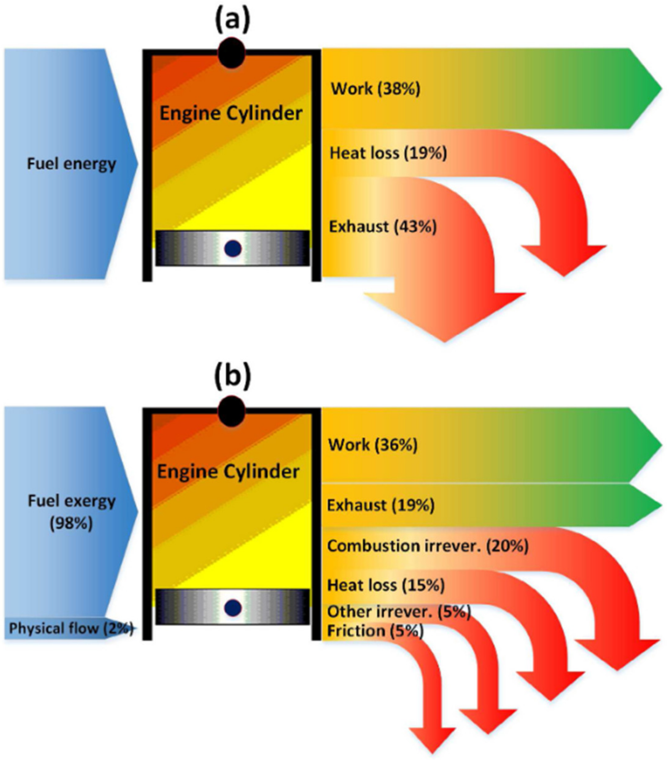
The minimization of heat loss, exhaust energy loss, and friction loss are critical to breaking through the bottleneck of maximum thermal efficiency;
Laser surface texturing, diamond-like carbon, thermal barrier coatings, and nano-lubricant additives are promising technologies for the reduction of engine energy losses;
Advanced variable controllers and variable displacement oil pumps are beneficial for minimizing energy losses.

1. Introduction

A quarter of the world’s power is provided by internal combustion engines (ICEs) operating on fossil fuels [1], which are subject to dual pressure from energy shortages and environmental concerns. Dramatic achievements in ICE technologies have driven pollutant emissions down 1000-fold in recent decades; meanwhile, there is great interest from researchers and manufacturers in improving the thermal efficiency of ICEs without significantly increasing purchases and operating costs in the short-to-medium term [2]. Innovations associated with technological developments continue to improve ICEs’ overall efficiency in combustion, after-treatment, control systems, ancillary systems, etc.
Since the fuel consumption of a vehicle is directly linked with its CO2 emissions. Several governments worldwide have put forward fuel economy or greenhouse gas (GHG) emissions standards for passenger vehicles and light commercial vehicles or light trucks [3]. The business strategies of automotive manufacturers worldwide have been heavily influenced by such increasingly strict regulations [4], which are among the most effective climate change mitigation measures implemented over the past decades. Heavy-duty vehicles (HDVs) account for more fuel use and CO2 emissions than light-duty vehicles, and although HDVs comprise a low percentage of the vehicle fleet, they are nevertheless responsible for almost one-quarter of road CO2 emissions [5]. While policy coverage for HDVs still lags behind that for cars and vans, substantial progress has been made recently in establishing efficiency and CO2 emissions standards for HDVs in India, China, and the European Union, among others. [6]. Europe has established its first ever CO2 standards for heavy-duty vehicles, with a 30% reduction in the fleet average needed by 2030, compared to 2019 [7]. Efficiency standards for vehicles urgently promote technological reforms of powertrain systems.
The thermodynamic limitations on the maximum efficiency of ICEs is a vital issue that constrains potential improvements of ICEs. Exergy analysis based on both the first and second laws of thermodynamics determines the ability and maximum useful work that a system can perform [8], and exergy would be destroyed via irreversible processes. Under typical engine performance conditions, the irreversible combustion takes up around 20% of the fuel’s capability to produce work, which implies that the maximum possible efficiency would be at best ~80%, assuming all other processes were ideal (not possible) [9]. However, in real engine conditions, in addition to the main exergy loss during combustion, the exergy loss in terms of heat loss, exhaust gases, and friction loss is responsible for 5–15%, 12–20%, and 4–8%, respectively [8,10], as shown in Figure 1. How to minimize the exergy losses and break through the bottleneck of maximum thermal efficiency is the most concerning issue for the development of engine technologies.
Theoretical investigations of engine thermal efficiency were conducted to quantify the maximum possible efficiency of ICEs under the most ideal conditions. Liu et al. [11] demonstrated the influences of various parameters—including compression ratio, heat transfer coefficient, and intake charge properties—on efficiency limits, via numerical studies based on the first law of thermodynamics. It was found that a certain threshold of high compression ratio combined with lean mixture combustion and optimal adiabatic conditions would lead to breakthrough in efficiency improvement. Caton [9] designed ideal conditions with no heat losses or mechanical friction under lean-burn or short-burn-duration conditions, in order to quantify the systematic thermodynamic evaluation of maximum efficiency. The importance of thermal constraints was discovered after each of the idealizations was relaxed. It was concluded that in-cylinder heat transfer was one of the largest impediments to maximizing thermal efficiency. Yao et al. [12] proposed a thermal cycle model coupled with energy and exergy analysis for marine engines, and the effects of critical combustion parameters (combustion quality index, combustion starting timing, and durations) on energy distribution were discussed.
Scientific and technological progress offers the most effective and direct approaches to erase engine losses. One of the trends is waste heat recovery (WHR) technology, making use of exhaust gases, where the basic method applied is turbochargers or superchargers—particularly in diesel engines [13,14]. Additionally, the use of WHR seems to be a very promising route to increase the energy efficiency of maritime engines, converting the thermal losses of ships into useful energy sources; as such, WHR has attracted extensive attention, with prospective fuel savings of up to 15% [15,16]. The irreversible combustion processes are mainly from the chemical reactions, heat transfer, and mixing associated with the combustion process. To reduce heat loss, many attempts are underway to insulate the combustion chamber walls. However, more special attention should be paid on the heating of charged air, because of the inevitable high-temperature insulating wall, which might cause emissions to decrease. Thermo-swing insulation technology [17,18] was proposed, with instantaneous changing of wall temperature based on the in-cylinder gas temperature. New insulation material framed from silica-reinforced porous anodized aluminum (SiRPA) is highlighted, with both heat-rejecting properties and reliability when used to coat the pistons, and improvement in thermal efficiency was achieved with increased brake power and exhaust loss. Regarding the reduction in friction loss, advanced low-viscosity engine oils, low-friction coatings, and surface texturing are the greatest potential techniques for reducing the friction of tribological components in reciprocating engines [19,20]. Meanwhile, the importance of effective variable discharge oil pumps [21,22] is increasing, with flexible adaption of the delivery of lubricant flow to meet engines’ practical demand, hence avoiding unnecessary pumping power and fuel consumption.
Advancements in combustion engine theory and new emerging technologies enable fuel savings by targeting diversified energy loss mechanisms. Thus far, the improvements in combustion engine performance arising from diversified fuel policy [23,24], fuel additives [25,26], and combustion strategies (reactivity controlled compression ignition (RCCI) or homogeneous charge compression ignition (HCCI)) [27,28,29] have been extensively reviewed. The authors’ group has conducted many studies on the applications of eco-friendly fuels such as polyoxymethylene dimethyl ether, natural gas, or gasoline-like fuels [30,31,32] to compression ignition engines in order to achieve better indicated thermal efficiency and ultralow emissions. Nevertheless, drastic improvements in brake thermal efficiency require both lower mechanical loss and higher indicated efficiency, which likewise challenge the tribological components and auxiliary devices. Mechanical losses are the consequence of energy losses due to the friction processes of moving parts (e.g., piston assembly, connection rod, crankshaft, and valve train), pumping systems, and the energy necessary for the movement of engine components. However, the losses are not constant across engine operating speed ranges; rather, they are growing with the increase in engine speed, as shown in Figure 2 [33]. The goal of this paper is to review recent studies and trends aimed toward reducing energy loss—including mechanical loss, cooling loss, pumping loss, etc.—in ICEs, so as to provide new insights with regard to further improvement of overall engine efficiency.

2. Low-Friction Technology

A general example of the breakdown of mechanical friction loss for ICEs [34] is given in Figure 3, where the piston and ring assembly account for the majority of friction losses, and the friction ratio due to the valve train and crank bearings is ~20%. Tribological technology supports the study of various lubrication and friction phenomena of the moving parts involved, by optimizing the structural design as well as the material and surface conditions, achieving both reduction in the friction coefficient and seizure resistance under fluid lubrication and boundary lubrication. Thus, particular attention was devoted to evaluating friction reduction behavior for each solution on low-friction pistons, low-friction engine bearings and valves, lubricating oil design, etc.
Efficient lubrication requires a comprehensive knowledge of the performance of lubrication regimes for the target component parts. Supported by the field of tribology, lubrication regimes are typically classified by the classic Stribeck curve, and Figure 4 outlines major engine components operating under various lubrication regimes [35], ranging from boundary to fluid film lubrication regimes. As depicted in Figure 4, the cam follower primarily operates in the boundary regime, in which the lubricant film is thin and the load is supported mainly or completely by asperity contact. The engine bearings operate in the hydrodynamic regime, where the lubricant film is sufficiently thick to sustain loads, and the asperity contact is negligible, whereas the piston rings work in both hydrodynamic and mixed regimes, occupying the transition region between the two mentioned lubrication regimes, which refers to conditions where the load is sustained by both the lubricant film and asperity contact. Therefore, opportunities to reduce the friction of the target engine component parts should be different. Friction reduction is necessary in order to reduce engine loss, but with the constraint that low-friction solutions should not affect system reliability, since the reduction in viscosity conceals “a trap as regards reliability” [36]. As shown in Figure 5, when reliability and low friction have to be treated at the same time, unfortunately there is not always an optimal solution [37]. The reliability of the targeted parts depends largely upon the amount of fluid film present between the surfaces. If a proper degree of film thickness is not achieved, it can cause changes in the friction coefficient, and potential failures (deformation or dynamic instability). In general, it is necessary to maintain the minimum film thickness at the safe limit.

2.1. Low-Friction Piston Ring–Liner (PRL) Interaction

Low-friction piston assemblies are mainly achieved by advanced surface texture, optimal design of piston structure and piston ring, and anti-friction coating technology. Moreover, engine downsizing, with less swept volume by the piston, leads to a decrease in the friction between the piston and the engine bore. Moreover, engine stroke-to-bore ratio also affects friction loss via two competing effects arising from crankshaft-bearing friction and power-cylinder friction. When the stroke-to-bore ratio becomes lower, the bearing friction becomes higher due to the larger piston area transferring more forces to the crankshaft bearings. On the other hand, the corresponding shorter stroke promotes declined power-cylinder friction originating at the ring–cylinder interface. Thus, optimal stroke-to-bore ratio must be considered in order to improve thermal efficiency [38].
Great effort has been devoted to improving the tribological behavior of piston ring–liner (PRL) interaction. Laser surface texturing (LST) technology is highlighted as one potential option for minimizing energy loss in the PRL interface, by creating an array of high-density micro-dimples on a metal surface via laser ablation. The macroscopic effect of such a microstructure enables the enhancement of the load capacity, wear resistance, and friction properties of the laser-treated surface. An experimental study by Zhan and Yang [39] discussed the effectiveness of LST on a cylinder piston ring system, emphasizing the distribution angle of dimples, which is responsible for lubrication reservoir and trapping of wear debris. Different surface textures were compared by Guo et al. [40] via a series of experimental tests on PRL worn surface texture features, lubrication oil contents, and abrasive particle characteristics. Concave dimples were found to be a better texturing pattern option than axial grooves over cylinder liners. Patel and Ramani [41] quantified a reduction in frictional energy loss of up to 26% with the use of LST on a piston ring.
Numerical modelling of mixed lubrication phenomena and realistic oil rheology is necessary in order to further optimize the PRL interface’s tribo-characteristics under normal or extreme real-engine scenarios. Patterns of surface texture with varied shapes and orientations were numerically investigated and optimized to decrease energy loss in spark ignition engines under warm operating conditions by Usman and Park [42]. The comparisons revealed that grooves perpendicular to the sliding direction (transverse grooves) are the best candidate for surface modifications. Aoki et al. [43] demonstrated the effects of the alignments and shapes of the grooves on the oil film thickness, as well as the friction coefficient on the piston skirt surface, via theory of elastic hydrodynamic lubrication. It was suggested that the grooves in the width direction could be more beneficial than those in the height direction for reducing the friction coefficient, along with shallow grooves with a large groove-to-gap ratio. Ahmed Ali et al. [44] performed an analytical study on the piston ring dynamics correlated with the tribological parameters of piston and ring assemblies, as well as engine combustion performance. The balance between the asperity (boundary) friction and the hydrodynamic friction was changed by the piston ring dynamics, contributing to the overall frictional power losses. Hence, optimization of lubricant flow is needed in order to ultimately improve the engine thermal efficiency.
Improvement of the PRL conformation is expected to reduce the friction and the oil losses, limited by the deformations under higher temperature gradients, thermal stresses, and mechanical loads under fired operations. Alshwawra et al. [45] proposed a methodology to achieve better PRL conformation and engine friction reduction via the enhancement of the liner’s straightness, roundness, and parallelism during the fired operation state, using a conical-shaped liner with elliptical cross-sections. Moreover, diamond-like carbon (DLC) coatings applied to aluminum alloy pistons are beneficial for achieving low friction, high wear resistance, and strong corrosion resistance. As shown in Figure 6, it was revealed with a DLC-coated PRL system, the weight of the engine piston and cylinder could be reduced by 5%, with 20% lower PRL friction, which ultimately leads to a 2–3% fuel economy improvement [46].

2.2. Low-Friction Bearings and Valve Trains

The bearings of the crankshaft and valve trains constitute the second-leading source of frictional losses in combustion engines, after the piston assembly. The development of reliable low-friction bearings should consider fatigue mechanisms in thermal aspects, as well as residual stress, elastic–plastic behavior, adaption of novel bearing materials, basic geometric design of bearings—such as bearing diameter or width—and bearings’ environment, such as circuit lubricant. Summer et al. [47] focused on the study of the frictional properties of bearing materials via laboratory tests in engine start–stop operations, providing as holistic a picture as possible regarding bearing friction performance in the boundary and mixed-friction sliding regimes; it was revealed that the outstanding friction and wear of the new polymer overlay was attributable to the dense filler structure of finely distributed MoS2, graphite, and Ti particles, preventing large areas of pure polymer. Knauder et al. [48] proposed a lubricant model to reflect non-Newtonian behavior as well as the piezoviscous effect, by which optimal lubricant oil was explored, with great potential for friction reduction in the bearings of heavy-duty trucks. Ligier and Noel [36] reviewed geometric solutions for low-friction bearings in three subdivisions: macroscopic level (bearing width and diameter), mesoscopic level (surface texture and microwaves), and microscopic level (roughness and waviness texture); it was concluded that the friction benefit could not be assessed by a separate factor, and that the gain would be around 2 g of CO2 per km on an NEDC cycle with low-friction bearing solutions. Alilakbari et al. [49] proposed a prediction model with a fatigue function for crankshaft failure of the heavy truck diesel engine, providing guidance towards the design of bearings and lubrication of the crankshaft system.
The valvetrain system involves a series of mechanical parts serving to open and close the intake and exhaust valves; it converts the rotary motion of the camshaft, at one end, to oscillatory motion of the valves at the other end. Cams and followers are taken as the most important tribological components, which account for 85–90% of the total friction losses from engine valvetrains [50]. Additionally, it is worthwhile to mention that the behavior of tappet rotation is affected by the tribochemistry between the lubricants and the coatings [50]. Lamborghini and Ricardo [51] created a closed loop consisting of modeling, analysis, and measurement, pursuing a clear sketch of an automotive engine valvetrain system. Acceptable agreements between measurements and calculations were achieved by specified lubricant rheological parameters. The numerical modelling of valvetrain systems is illustrated in Figure 7a, and the predicted mean calculated power loss due to the cam–tappet contact, tappet–bore contact translation, and tappet–bore contact rotation are plotted in Figure 7b against camshaft speeds.
Current studies on the low friction loss of valvetrain systems are mainly focused on DLC coatings. Figure 8 depicts the effects of various coatings on valvetrain friction torque against engine speeds. A reduction of 45% in friction torque was observed when using a ta-C coating compared with the result for a conventional phosphate coating on carburized steel at an engine speed of 2000 rpm [46]. A novel multiphysics analytical model considering the mechanical, thermal, and tribological properties of DLC coatings was proposed by Lyu et al. [52], and their simulation results predicted a reduction in friction loss of up to 45% within a cam cycle of the DLC-coated (a-C:H) cam/tappet under a heavy engine load. Even though the wear condition became progressively more severe as the ambient temperature increased, the wear resistance of the DLC coatings was still impressive.

2.3. Improvement of Lubricants System

Lubricants and additives in modern engines perform significant functions and fulfill many requirements. Meanwhile, lubricant additives work as antioxidants, corrosion/rust inhibitors, friction modifiers, viscosity index improvers, and anti-wear additives [53]. However, many friction modifiers and anti-wear additives contain metallic, sulfurous, and phosphoric chemicals, which can cause adverse effects on the emissions after treatment. Therefore, proper design of high-quality lubricant additives and optimal fluid formulations that differ between engine components and cycles are promising technologies for friction loss reduction.
Recently, studies of nano-lubricants with hybrid nanomaterial additives are attracting great interest with regard to upgrading the tribological properties by forming protective films on surfaces, all the while creating a rolling effect between the sliding surfaces [54]. Positive improvements in both thermal and tribological properties have been demonstrated by nano-lubricants composed of base elements such as Fe, C, Co, Cu, and other candidates. However, oxides—such as CuO and ZnO—manifest themselves stably over a long time, mainly because of the hydroxyl or carboxyl clusters on their surface, which boost their interaction with surfactants to improve their dispersion stability in non-polar media [55]. Ali et al. [56] evaluated the wear and friction behavior of nano-lubricants including hybrid nanomaterials of TiO2 and Al2O3 under reciprocating test conditions, in order to mimic piston ring and cylinder liner contact. The microstructures and morphology profiles of the tribofilms during frictional contact are demonstrated in Figure 9. It was noticeable that the Al2O3 and TiO2 hybrid nanoparticles produced a protective film on the worn surfaces, resembling an ultrathin lubricating coating, beneficial for minimizing frictional power losses (reduced by almost 50%) and enhanced anti-wear/scuffing ability. In addition, based on summaries of recent studies of nano-lubricants in engines [57], Al2O3 and TiO2 nanoparticles are the most efficient non-additives to SAE-40 engine oil, with a maximum of 86% reduction in friction coefficient, as well as 29% wear reduction and, consequently, reduction in brake-specified fuel consumption (BSFC). In addition, exergy economics studies are expected to promote a decisive selection of efficient lubricants [57].
Referred to as the “heart of an engine”, the oil pump has a significant impact on assuring the intended flowrates of lubricant supply. In conventional oil pumps with fixed displacement, the oil flow delivery is typically proportional to the engine speed. If adequate oil is supplied at high engine operating speeds, the pumps are inevitably oversized so as to supply an excess flow of oil at low engine operating speeds, making the pumps inherently inefficient and increasing engine power losses. On the other hand, variable displacement oil pumps (VDOPs) are designed for adaptive control of the oil flow in order to elaborately match actual engine demands.
Vane oil pumps are operated by a solenoid in order to actuate the variable eccentricity between the cam ring and the rotor; therefore, the volume of the pump itself, as well as the oil flow supply, could be dynamically modulated based on the actual requirements of engine oil pressure [58], which are highlighted in potential flow savings. Arata et al. [59] claimed that vane oil pumps would become the standard in the future due to their significant role in driving torque reduction, which has been demonstrated in particular during engine cold starts. Doikin et al. [60] presented a life prediction model for the advancement of online health monitoring and diagnostics of the oil pumps, based on ECU data-driven analysis; this revealed the factors resulting in high cycle fatigue, oil aeration, and pump degradation, providing an important direction of further design research for VDOPs.
Yamamoto et al. [61] developed a novel internal-gear fully variable discharge oil pump (F-VDOP), as shown in Figure 10. This new oil pump was able to provide adaptive oil pressure over temperatures ranging from −10 °C to hot conditions. With an improved internal gear tooth profile, a friction reduction of 34% on the rotor was achieved, compared with the conventional trochoidal tooth profile, along with a 1.2% improvement in fuel economy under the LA#4 cold test cycle.

3. Technologies of Pumping Loss Reduction

Engine gas exchange processes and mass flow rates predominate the pumping loss of intake stroke, as well as the charging efficiency. Variable-valve systems have been widely investigated with regard to pumping loss reduction by varying the opening–closing timing, opening magnitude (lift amount), and opening period (operation angle) of valves, and further improvement of engine efficiency was explored through integration with direct-injection systems. Application of the Miller cycle, which is characterized by a shorter compression stroke relative to the expansion stroke as a result of either early or late intake valve closing (EIVC or LIVC), has the potential to mitigate the pumping loss by controlling the charge amount. Moreover, modulated pressure and mass flow pulsations influenced by Miller cycle engine combustion combined with turbocharger systems can reduce pumping loss to a great extent.
For gasoline engines, the implementation of load control at low loads via the throttle valve gives rise to pumping loss during gas exchange strokes. A combination of the Miller cycle and a modern, highly boosted, downsized gasoline engine was studied by Li et al. [62] to explore a potential technical roadmap for reducing pumping loss at low loads, while improving anti-knock performance at high loads. It was found that the decrease in the pumping loss with EIVC was greater than that with LIVC. A comparative study on the influential factors in pumping loss reduction resulting from continuous variable valve lift (CVVL) and variable valve timing (VVT) was carried out on gasoline engines [63]. As seen in Figure 11, considerable differences in intake activities between VVT engines and CVVL engines were observed at the same target load [63]. It was concluded that in comparison to VVT engines, CVVL engines have greater potential for minimizing pumping loss at low-to-medium loads, and as the valve lift increases to a certain value, the downtrend of pumping loss becomes slower, approaching the theoretical lower limit.
There are many ongoing studies exploring the positive outcomes of VVT and LIVC technologies in diesel engines [64,65,66]. Daimler proposed and patented an asymmetric turbocharger without mobile vane actuation, with more compact parts than the conventional variable-geometry turbocharger (VGT); it provides more effective turbocharging performance, with reduced pumping loss, and is able to drive the EGR rate up to 35% at full load on Detroit Diesel’s HD platform [67]. The modulation strategies of LIVC and EIVC in low-loaded diesel engines to optimize exhaust temperature management efficiency were examined by numerical methods [68]. However, it was found that the alteration in exhaust temperature was inversely related to the change in volumetric efficiency, thus affecting the pumping loss and final fuel efficiency. Therefore, increasing the exhaust temperature via VVT and LIVC modulation is worthy of consideration. The divided exhaust period (DEP) concept was proposed by Bharath et al. [69], as shown in Figure 12, with the actuated exhaust valves separated by variable valve actuation. The exhaust flow was designed to be split into two manifolds, thereby lowering the overall engine backpressure as well as decreasing pumping losses—especially at medium and high loads. Zhu et al. [70] performed numerical studies to guide the diesel engine turbocharging strategy, with variable geometry and two-stage, asymmetric twin-scroll turbocharging under various EGR rates. When higher EGR driving rates (>29%) were applied, asymmetric twin-scroll turbocharging was the best option, with lower pumping loss and lower BSFC.

4. Low-Cooling-Loss Technologies

Cooling systems play a necessary role in keeping the engine block at a proper temperature level, preventing the engine block from overheating, but at the cost of great coolant heat loss. The performance of engine cooling systems has improved as the power output and density of ICEs gradually increases. Recent studies have integrated thermal management features into the engine network, in order to enable an optimized balance between engine warm-up, cabin condition, catalyst light-off, and combustion performance. As reported by Jung et al. [71], the heat loss from coolant accounts for 79.1% of the total cooling loss, with a further 16.1% from lubricating oil, and 4.8% caused by convection and radiation transfer, as determined by energy flow analysis of diesel engine thermal management. Hence, approaches to achieve lower cooling loss, controllable wall temperature by heat insulation, and optimal coolant circuits have attracted more attention in recent years.
As a very promising approach to minimizing the cooling loss from ICEs, thermal piston insulation coated with low-thermal-conductivity materials has been studied since the 1980s [72,73]. However, if the temperature of the piston surface stays higher during the intake stroke, the intake air may be heated, thereby causing the volumetric efficiency to drop, along with deteriorated NOx and soot emissions [74]. To overcome these issues, Toyota proposed the concept of “temperature swing heat insulation” (TSHI) [75], which is characterized by transient temperature fluctuation of the combustion chamber wall coated with low-heat-conductivity and -capacity materials. The coat consists of empty particles and a low-heat-conductivity binder, which incorporate trapped air, resulting in low density and thermal conductivity. Meanwhile, the hollow particles are also strong enough to resist the thermal stresses during engine operation. As shown in Figure 13, compared with the traditional strategy of thick, ceramic-coated heat insulation, TSHI facilitates the wall temperature fluctuation or swing with gas temperature throughout the cycle, thus leading to a lower surface temperature during the intake stroke and a higher temperature during the combustion stroke, which enables the reduction in heat loss without heating the intake air. Recently, an improved generation of low-heat-capacitance (thermal conductivity < 0.35 W/m-K, thermal heat capacitance < 500 kJ/m3-K, and density < 0.35 g/cm3) thermal barrier coatings (TBCs) has been developed [76]. When applied to the piston and cylinder head in a natural gas engine, the updated TBC properties brought a 1.3% improvement in thermal efficiency and a 4.6% decrease in fuel consumption through lowered heat rejection, with no deterioration in volumetric efficiency or engine knock tendency [76].
In contrast with conventional mechanical water pumps, electronic water pumps are alternatively used in advanced engine cooling systems, providing more flexible control of the coolant flow rate, which previously depended heavily on engine driving conditions such as loads and speeds. The pump R&D stand concept proposed by Bitsis and Miwa [77] allows for rapid demonstration of coolant and lubricant flow reduction technologies, and coolant flow variations have been tested by an electrically driven coolant pump combined with different transmission ratios. This concept reveals the maximum possible benefits with regard to brake thermal efficiency (BTE). Granitz et al. [78] used electric coolant pumps on a Euro VI certified 6-cylinder in-line HD diesel engine with two cooling circuits. The separation layout of the cooling circuits presents the opportunity to ascertain the charge air temperature level on demand, and improves the warm-up behavior. It was concluded that the engine coolant pump offers an increased degree of freedom that has a significant influence on parasitic loss reduction and BTE improvement.
Numerous cooling strategies for ICEs—including nucleate boiling and thermal management intelligent systems (THEMIS)—have been developed in the past. Implementation of alternative strategies—by either replacing conventional cooling components or adding electrical components—has shown great potential for the improvement of engine efficiency and performance. Castiglione et al. [79] presented a robust model predictive control (MPC) methodology integrated with heat transfer prediction in the presence of single-phase forced convection and nucleate or saturated boiling, in order to optimize the coolant flow rate using an electric pump for ICEs. With the intended strategy, the coolant flow rate was effectively reduced by almost 60%, and it took 3 min less to warm the engine wall temperature up to 120 °C compared with a standard mechanical pump. Haghighat et al. [80] developed a cooling system model of an engine with controllable components, including an electrical water pump, electrical fan, and heated thermostat. Driven by numerous experiments on a 1.4 L dual-fuel engine, the control program suggested a 1.1% decrease in fuel consumption under the NEDE cycle by the intelligent cooling system, along with noticeable reductions in CO and HC emissions. In fact, the warm-up time of the coolant and lubricating oil considerably influences the engine catalyst light-off performance [81]; therefore, the thermal management methods of the catalytic converter should be further explored when optimizing the engine cooling systems.

5. Energy Distribution and Efficiency in Modern ICEs

To evaluate the improvements in efficiency from various promising engine technologies amidst increasingly stringent standards, it is imperative to fully comprehend the nature and magnitude of losses by performing higher level thermodynamic analysis of the energy flow in modern ICEs. Studies that attempted to deliver detailed breakdowns of engine energy flows and loss mechanisms would be favorable for predicting the benefits of novel technologies on overall engine efficiency. Thiruvengadam et al. [82] concentrated on benchmarking the engine efficiency and energy distribution, with an HD engine of a long-haul truck as a reference for the baseline technology, as illustrated in Figure 14. A combination of incremental improvements in friction losses was extensively investigated, via advanced piston designs, lubrication, and water pump and oil pump designs, along with lower differential pressure EGR systems, and better handling of airflow through the intake and exhaust systems. Achieving compliance with the 2017 GHG emissions and 2020–future (2020+) expectations would definitely enhance engine efficiency gains.
Cummins Inc. engaged in developing a new HD diesel engine delivering greater than 50% BTE under the SuperTruck program goals [83]. A system-level optimization was undertaken, mainly focused on increased compression ratio; higher injection rate; carefully matched, highly efficient turbocharging; variable lube oil pumps; variable cooling components; and low restriction after treatment. Subsystem requirements and technology options were applied to elucidate the system-level planning based on the understanding of interactions of energy breakdown in order to enable more than 50% BTE. Moreover, the potential technical improvements to deliver HD diesel engine efficiency of 55% BTE or greater in the short term, with additional waste heat recovery (WHR) systems, were discussed along with expectations.
As transportation now looks to a decarbonized future, the versatility of ICE operating processes is likely to be critical. Further studies allowing the collaboration of specialists from different disciplines—such as chemistry, manufacturing, materials science, and mechanical engineering—will be important to improve the quality and performance of the coating materials and engine components. There is much interest in low-carbon fuels—such as hydrocarbons, liquids, gases, etc.—to be used in ICEs to achieve a lower GHG footprint. With further improvements in thermal efficiency close to 60% in the short term, these can ease the expansion of renewable electricity generation by providing alternative storage options when generation exceeds demand. All available technologies should be developed simultaneously and used to mitigate the environmental impacts of transport, rather than banning the sale of new ICE vehicles.

6. Conclusions

Energy-saving standards for vehicles urgently promote technological enhancement and reform of powertrain systems. Increasingly stringent CO2 emissions standards impose high pressures for both light-duty and heavy-duty vehicles. Accordingly, breaking through the thermodynamic limitations on the maximum efficiency of ICEs is the most pressing issue for researchers and manufactures, with the minimization of heat loss, exhaust energy loss, friction loss, etc. Literature surveys are presented in this paper to summarize recent promising technologies capable of fuel savings by targeting diversified energy loss mechanisms. The major development trends will be focused on the following:
  • Tribological technology supports the study of various lubrication and friction phenomena of the moving parts involved, by optimizing structural design as well as material and surface conditions, achieving both reduced friction coefficient and increased wear resistance. However, low-friction solutions should be balanced with system reliability, since the reduction in viscosity conceals a trap as regards reliability according to lubrication regimes classified by the Stribeck curve;
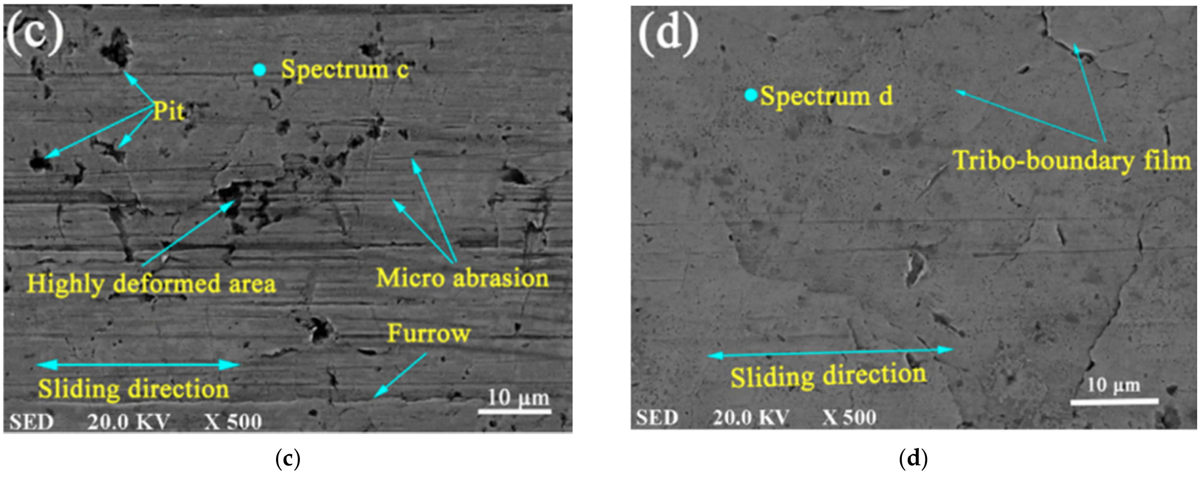
  • Novel anti-friction coating technologies intended for tribological components are expected to be a promising approach for the improvement of the tribo-characteristics of piston ring–liner (PRL) assemblies and valvetrain systems. Laser surface texturing (LST) contributes to great reductions in frictional losses by creating high-density micro-dimples on the PRL’s worn surface. Meanwhile diamond-like carbon (DLC) coatings on PRL and valvetrain systems are impressive for their low friction, high wear resistance, and strong corrosion resistance. Furthermore, nano-lubricants with hybrid nanomaterial additives are attracting great interest for their potential to upgrade the tribological properties by forming protective films on surfaces, while creating a rolling effect between sliding surfaces;
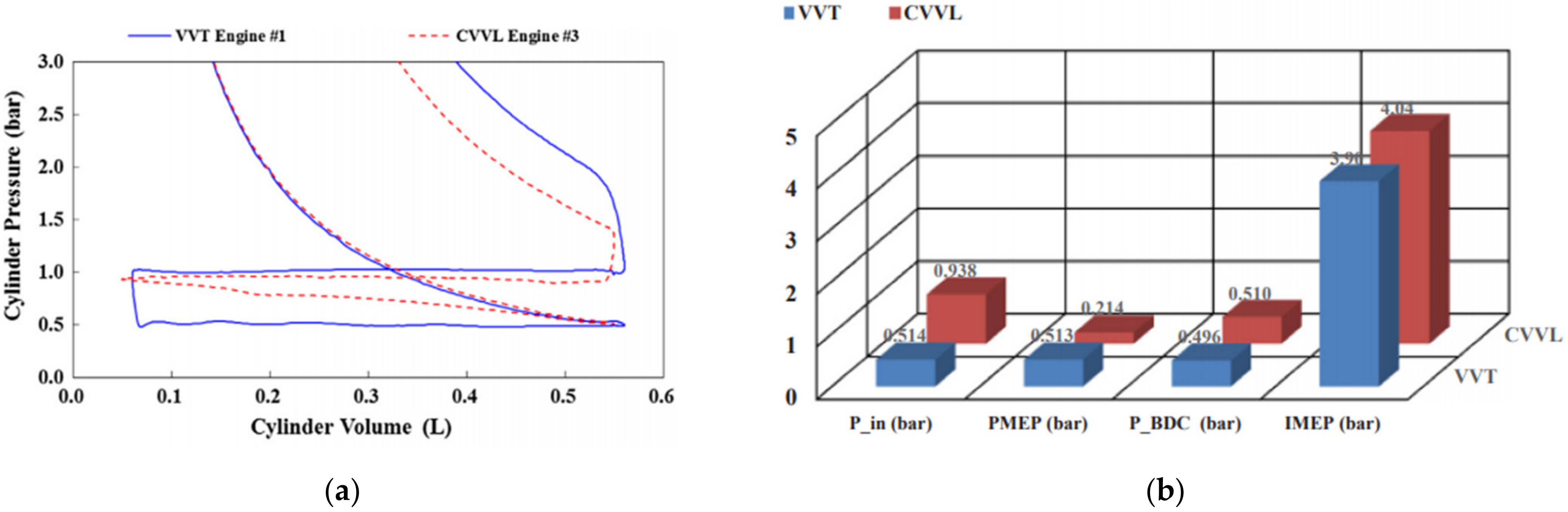
  • Advanced variable controllers make the engine working process more flexible, in order to achieve the best possible thermal efficiency. Variable-valve systems, by varying the opening–closing timing, opening lift magnitude, and opening period of valves, are able to mitigate the pumping loss caused by gas exchange and mass flow pulsations. In addition, variable displacement oil pumps and electronic water pumps provide moderate flow of medium based on actual engine demand, without additional pumping work output, thus reducing mechanical loss;
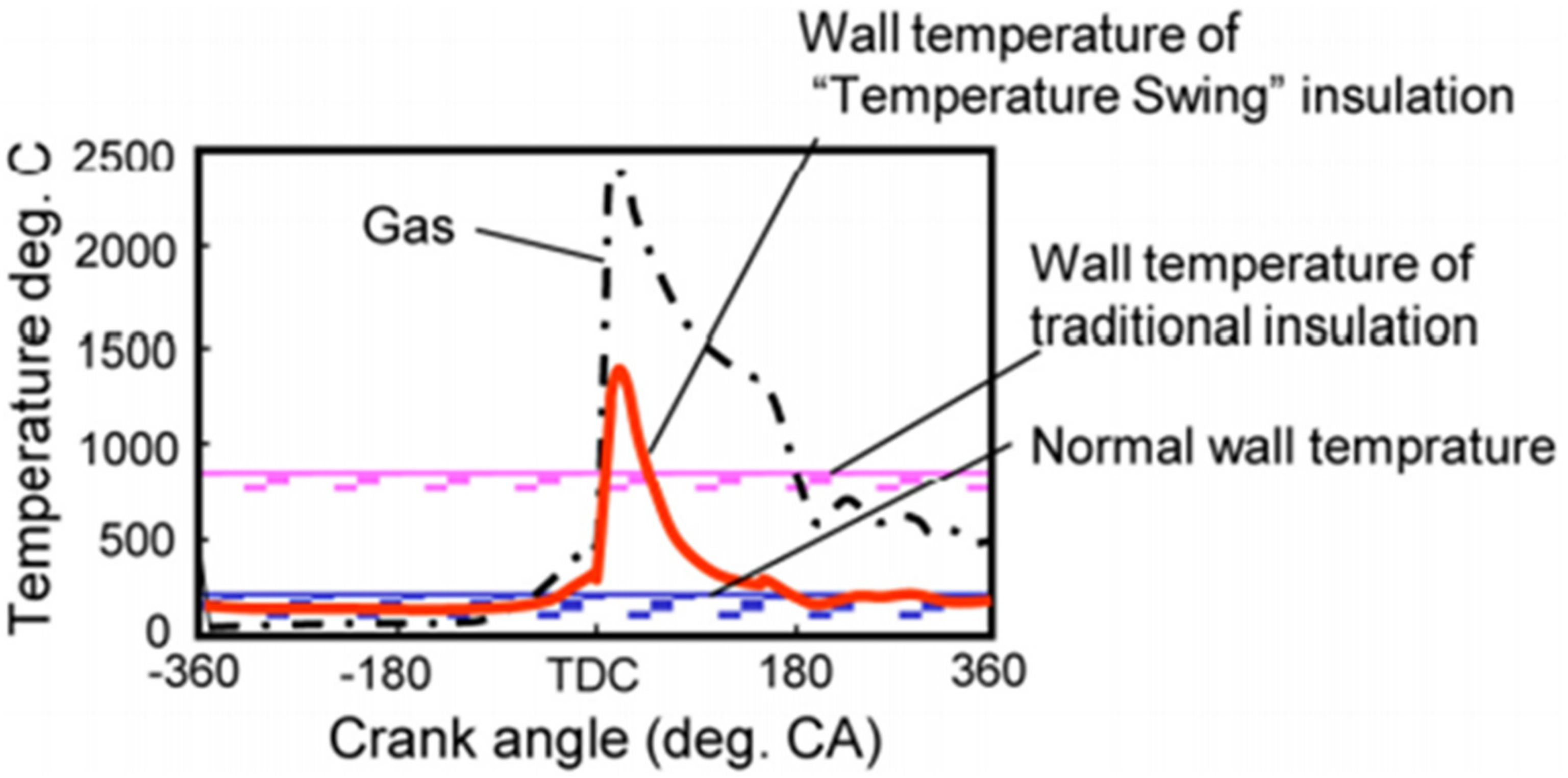
  • Thermal management enables an optimized balance between engine thermal load, cabin condition, catalyst light-off, and combustion performance. The new concept of “temperature swing heat insulation” (TSHI) with low-heat-capacitance thermal barrier coatings (TBCs) was successful in facilitating fluctuations in the wall temperature and swinging the gas temperature throughout the cycle, enabling reduction in heat loss without intake air heating. Meanwhile, thermal management intelligent systems (THEMIS) are efficient in coordinating various cooling system components to achieve efficiency targets.

Author Contributions

Conceptualization, Z.W. and S.S.; methodology, Z.W.; formal analysis, Z.W., Z.L. and W.Y.; investigation, Z.W.; resources, Z.W., Z.L., W.Y.; data curation, Z.W.; writing—original draft preparation, Z.W., S.S.; writing—review and editing, Z.W., S.S. and Z.L.; supervision, S.S. All authors have read and agreed to the published version of the manuscript.

Funding

This research received no funding.

Data Availability Statement

Not applicable.

Conflicts of Interest

The authors declare no conflict of interest.

References

  1. BP. Statistical Review of World Energy. BP Magazine, June 2018. Available online: https://www.bp.com/en/global/corporate/energy-economics/statistical-review-of-world-energy.html (accessed on 10 July 2021).
  2. Reitz, R.D.; Ogawa, H.; Payri, R.; Fansler, T.; Kokjohn, S.; Moriyoshi, Y.; Agarwal, A.K.; Arcoumanis, D.; Assanis, D.; Bae, C.; et al. The future of the internal combustion engine. Int. J. Engine Res. 2020, 21, 3–10. [Google Scholar] [CrossRef] [Green Version]
  3. Chart Library: Passenger Vehicle Fuel Economy. Available online: https://theicct.org/chart-library-passenger-vehicle-fuel-economy (accessed on 10 July 2021).
  4. Awad, O.I.; Ma, X.; Kamil, M.; Ali, O.M.; Zhang, Z.; Shuai, S. Particulate emissions from gasoline direct injection engines: A review of how current emission regulations are being met by automobile manufacturers. Sci. Total Environ. 2020, 718, 137302. [Google Scholar] [CrossRef]
  5. Zacharof, N.; Fontaras, G.; Ciuffo, B.; Tansini, A.; Prado-Rujas, I. An estimation of heavy-duty vehicle fleet CO2 emissions based on sampled data. Transp. Res. Part D Transp. Environ. 2021, 94, 102784. [Google Scholar] [CrossRef]
  6. Trucks and Buses. Available online: https://www.iea.org/reports/trucks-and-buses (accessed on 10 July 2021).
  7. Reducing CO2 Emissions from Heavy-Duty Vehicles. Available online: https://ec.europa.eu/clima/policies/transport/vehicles/heavy_en (accessed on 10 July 2021).
  8. Rakopoulos, C.D.; Giakoumis, E.G. Second-law analyses applied to internal combustion engines operation. Prog. Energy Combust. Sci. 2006, 32, 2–47. [Google Scholar] [CrossRef]
  9. Caton, J.A. Maximum efficiencies for internal combustion engines: Thermodynamic limitations. Int. J. Engine Res. 2018, 19, 1005–1023. [Google Scholar] [CrossRef]
  10. Razmara, M.; Bidarvatan, M.; Shahbakhti, M.; Robinett III, R.D. Optimal exergy-based control of internal combustion engines. Applied Energy 2016, 183, 1389–1403. [Google Scholar] [CrossRef] [Green Version]
  11. Liu, H.; Ma, J.; Tong, L.; Ma, G.; Zheng, Z.; Yao, M. Investigation on the Potential of High Efficiency for Internal Combustion Engines. Energies 2018, 11, 513. [Google Scholar] [CrossRef] [Green Version]
  12. Yao, Z.M.; Qian, Z.Q.; Li, R.; Hu, E. Energy efficiency analysis of marine high-powered medium-speed diesel engine base on energy balance and exergy. Energy 2019, 176, 991–1006. [Google Scholar] [CrossRef]
  13. Feneley, A.J.; Pesiridis, A.; Andwari, A.M. Variable geometry turbocharger technologies for exhaust energy recovery and boosting-A Review. Renew. Sustain. Energy Rev. 2017, 71, 959–975. [Google Scholar] [CrossRef]
  14. Zhao, X.; Qiu, L.; Wei, K.; Zhang, Z.; Deng, Y.; Han, D.; Liu, G. Experimental investigation on performance and economy characteristics of a diesel engine with variable nozzle turbocharger and its application in urban bus. Energy Convers. Manag. 2019, 193, 149–161. [Google Scholar] [CrossRef]
  15. Zhu, S.; Zhang, K.; Deng, K. A review of waste heat recovery from the marine engine with highly efficient bottoming power cycles. Renew. Sustain. Energy Rev. 2019, 120, 109611. [Google Scholar] [CrossRef]
  16. Xu, B.; Rathod, D.; Yebi, A.; Filipi, Z.; Onori, S.; Hoffman, M. A comprehensive review of organic rankine cycle waste heat recovery systems in heavy-duty diesel engine applications. Renew. Sustain. Energy Rev. 2019, 107, 145–170. [Google Scholar] [CrossRef]
  17. Wakisaka, Y.; Inayoshi, M.; Fukui, K.; Kosaka, H.; Hotta, Y.; Kawaguchi, A.; Takada, N. Reduction of Heat Loss and Improvement of Thermal Efficiency by Application of “Temperature Swing” Insulation to Direct-Injection Diesel Engines. SAE Int. J. Engines 2016, 9, 1449–1459. [Google Scholar] [CrossRef]
  18. Kawaguchi, A.; Wakisaka, Y.; Nishikawa, N.; Kosaka, H.; Yamashita, H.; Yamashita, C.; Iguma, H.; Fukui, K.; Takada, N.; Tomoda, T. Thermo-swing insulation to reduce heat loss from the combustion chamber wall of a diesel engine. Int. J. Engine Res. 2018, 20, 805–816. [Google Scholar] [CrossRef]
  19. Knauder, C.; Allmaier, H.; Sander, D.E.; Sams, T. Investigations of the Friction Losses of Different Engine Concepts. Part 1: A Combined Approach for Applying Subassembly-Resolved Friction Loss Analysis on a Modern Passenger-Car Diesel Engine. Lubricants 2019, 7, 39. [Google Scholar] [CrossRef] [Green Version]
  20. Rahman, H.A.; Ghani, J.A.; Mahmood, W.M.F.W. A brief review on friction reduction via dimple structure for piston engine. World Rev. Sci. Technol. Sustain. Dev. 2018, 14, 147–164. [Google Scholar] [CrossRef]
  21. Nishida, Y.; Toyoda, F.; Terashima, H.; Ono, H.; Nunami, K. Development of Continuously Variable Discharge Oil Pump. SAE Int. J. Engines 2018. [Google Scholar] [CrossRef]
  22. Ramkumar, J.; Ranjit, G.; Sarath, V.; Vikraman, V.; Suresh, B.; Babu, N.P.; Amit, M. Design Optimization of Lubrication System for a Four-Cylinder Diesel Engine. In Advances in Automotive Technologies; Springer: Singapore, 2021; pp. 139–155. [Google Scholar]
  23. Hall, C.; Kassa, M. Advances in combustion control for natural gas–diesel dual fuel compression ignition engines in automotive applications: A review. Renew. Sustain. Energy Rev. 2021, 148, 111291. [Google Scholar] [CrossRef]
  24. Tamilselvan, P.; Nallusamy, N.; Rajkumar, S. A comprehensive review on performance, combustion and emission characteristics of biodiesel fuelled diesel engines. Renew. Sustain. Energy Rev. 2017, 79, 1134–1159. [Google Scholar] [CrossRef]
  25. Kegl, T.; Kralj, A.K.; Kegl, B.; Kegl, M. Nanomaterials as fuel additives in diesel engines: A review of current state, opportunities, and challenges. Prog. Energy Combust. Sci. 2020, 83, 100897. [Google Scholar] [CrossRef]
  26. Nanthagopal, K.; Kishna, R.S.; Atabani, A.E.; Al-Muhtaseb, A.H.; Kumar, G.; Ashok, B. A compressive review on the effects of alcohols and nanoparticles as an oxygenated enhancer in compression ignition engine. Energy Convers. Manag. 2020, 203, 112244. [Google Scholar] [CrossRef]
  27. Splitter, D.; Wissink, M.; Delvescovo, D.; Reitz, R.D. RCCI Engine Operation Towards 60% Thermal Efficiency. SAE Int. 2013. [Google Scholar] [CrossRef]
  28. Li, J.; Yang, W.; Zhou, D. Review on the management of RCCI engines. Renew. Sustain. Energy Rev. 2016, 69, 65–79. [Google Scholar] [CrossRef]
  29. Telli, G.; Altafini, C.; Costa, C.; Rosa, J.; Martins, M.; Rocha, L. A comprehensive review of homogeneous charge compression ignition (HCCI) engines: Advantages, challenges and evolution. SAE Tech. Pap. 2021. [Google Scholar] [CrossRef]
  30. Awad, O.I.; Ma, X.; Kamil, M.; Ali, O.M.; Ma, Y.; Shuai, S. Overview of polyoxymethylene dimethyl ether additive as an eco-friendly fuel for an internal combustion engine: Current application and environmental impacts. Sci. Total Environ. 2020, 715, 136849. [Google Scholar] [CrossRef] [PubMed]
  31. Song, H.; Liu, C.; Li, F.; Wang, Z.; He, X.; Shuai, S.; Wang, J. A comparative study of using diesel and PODEn as pilot fuels for natural gas dual-fuel combustion. Fuel 2017, 188, 418–426. [Google Scholar] [CrossRef]
  32. Yu, L.; Shuai, S.; Li, Y.; Li, B.; Liu, H.; He, X.; Wang, Z. An experimental investigation on thermal efficiency of a compression ignition engine fueled with five gasoline-like fuels. Fuel 2017, 207, 56–63. [Google Scholar] [CrossRef]
  33. Mechanical Efficiency and Friction Mean Effective Pressure (FMEP). Available online: https://x-engineer.org/automotive-engineering/internal-combustion-engines/performance/mechanical-efficiency-friction-mean-effective-pressure-fmep/ (accessed on 15 July 2021).
  34. Mihara, Y. Research Trend of Friction Loss Reduction in Internal Combustion Engines. Tribol. Online 2017, 12, 82–88. [Google Scholar] [CrossRef] [Green Version]
  35. Chong WW, F.; Hamdan, S.H.; Wong, K.J.; Yusup, S. Modelling Transitions in Regimes of Lubrication for Rough Surface Contact. Lubricants 2019, 7, 77. [Google Scholar] [CrossRef] [Green Version]
  36. Ligier, J.L.; Noel, B. Friction reduction and reliability for engines bearings. Lubricants 2015, 3, 569–596. [Google Scholar] [CrossRef] [Green Version]
  37. Sarkar, S.; Golecha, K.; Kohli, S.; Kalmegh, A.; Yadav, S. Robust Design of Spiral Groove Journal Bearing. SAE Int. J. Mater. Manuf. 2016, 9, 206–216. [Google Scholar] [CrossRef]
  38. Filipi, Z.S.; Assanis, D.N. The effect of the stroke-to-bore ratio on combustion, heat transfer and efficiency of a homogeneous charge spark ignition engine of given displacement. Int. J. Engine Res. 2000, 1, 191–208. [Google Scholar] [CrossRef]
  39. Zhan, J.; Yang, M. Investigation on Dimples Distribution Angle in Laser Texturing of Cylinder–Piston Ring System. Tribol. Trans. 2012, 55, 693–697. [Google Scholar] [CrossRef]
  40. Guo, Z.; Yuan, C.; Liu, P.; Peng, Z.; Yan, X. Study on Influence of Cylinder Liner Surface Texture on Lubrication Performance for Cylinder Liner–Piston Ring Components. Tribol. Lett. 2013, 51, 9–23. [Google Scholar] [CrossRef]
  41. Patel, V.K.; Ramani B, M. Investigation on laser surface texturing for friction reduction in multi cylinder internal combustion engine. Int. J. Ambient. Energy 2019. [Google Scholar] [CrossRef]
  42. Usman, A.; Park, C.W. Optimizing the tribological performance of textured piston ring–liner contact for reduced frictional losses in SI engine: Warm operating conditions. Tribol. Int. 2016, 99, 224–236. [Google Scholar] [CrossRef]
  43. Aoki, H.; Hayakawa, K.; Suda, N. Numerical analysis on effect of surface asperity of piston skirt on lubrication performance. Procedia Manuf. 2018, 15, 496–503. [Google Scholar] [CrossRef]
  44. Ahmed Ali, M.K.; Xianjun, H.; Fiifi Turkson, R.; Ezzat, M. An analytical study of tribological parameters between piston ring and cylinder liner in internal combustion engines. Proc. Inst. Mech. Eng. Part K J. Multi-Body Dyn. 2016, 230, 329–349. [Google Scholar] [CrossRef]
  45. Alshwawra, A.; Pohlmann-Tasche, F.; Stelljes, F.; Dinkelacker, F. Enhancing the Geometrical Performance Using Initially Conical Cylinder Liner in Internal Combustion Engines—A Numerical Study. Appl. Sci. 2020, 10, 3705. [Google Scholar] [CrossRef]
  46. Kano, M. Overview of DLC-Coated Engine Components. In Coating Technology for Vehicle Applications; Springer International Publishing: Berlin/Heidelberg, Germany, 2015; pp. 37–62. [Google Scholar]
  47. Summer, F.; Grün, F.; Offenbecher, M.; Taylor, S. Challenges of friction reduction of engine plain bearings—Tackling the problem with novel bearing materials. Tribol. Int. 2019, 131, 238–250. [Google Scholar] [CrossRef]
  48. Knauder, C.; Allmaier, H.; Sander, D.E.; Salhofer, S.; Reich, F.M.; Sams, T. Analysis of the Journal Bearing Friction Losses in a Heavy-Duty Diesel Engine. Lubricants 2015, 3, 142–154. [Google Scholar] [CrossRef]
  49. Alilakbari, K.; Imanparast, M.; Nejad, R.M. Microstructure and fatigue fracture mechanism for a heavy-duty truck diesel engine crankshaft. Sci. Iran. 2018. [Google Scholar] [CrossRef] [Green Version]
  50. Al-Jeboori, Y.; Kosarieh, S.; Ofune, M.; Morina, A.; Neville, A. Measuring tappet rotation in a valvetrain rig when lubricated in a fully formulated oil containing MoDTC-type friction modifier. Tribol. Int. 2018, 121, 442–449. [Google Scholar] [CrossRef]
  51. Calabretta, M.; Cacciatore, D.; Carden, P. Valvetrain Friction—Modeling, Analysis and Measurement of a High Performance Engine Valvetrain System. SAE Int. J. Engines 2010, 3, 72–84. [Google Scholar] [CrossRef]
  52. Lyu, B.; Meng, X.; Zhang, R.; Cui, Y. A Comprehensive Numerical Study on Friction Reduction and Wear Resistance by Surface Coating on Cam/Tappet Pairs under Different Conditions. Coatings 2020, 10, 485. [Google Scholar] [CrossRef]
  53. Mortier, R.M.; Fox, M.F.; Orszalik, S.T. Chemistry and Technology of Lubricants, 3rd ed.; Springer: Dordrecht, The Netherlands, 2010. [Google Scholar]
  54. Tang, Z.; Li, S. A review of recent developments of friction modifiers for liquid lubricants (2007-present). Curr. Opin. Solid State Mater. Sci. 2014, 18, 119–139. [Google Scholar]
  55. Chen, Y.; Renner, P.; Liang, H. Dispersion of nanoparticles in lubricating oil: A critical review. Lubricants 2019, 7, 7. [Google Scholar] [CrossRef] [Green Version]
  56. Ali, M.K.A.; Hou, X.; Mai, L.; Chen, B.; Turkson, R.F.; Cai, Q. Reducing frictional power losses and improving the scuffing resistance in automotive engines using hybrid nanomaterials as nano-lubricant additives. Wear 2016, 364–365, 270–281. [Google Scholar] [CrossRef]
  57. Hatami, M.; Hasanpour, M.; Jing, D. Recent developments of nanoparticles additives to the consumables liquids in internal combustion engines: Part II: Nano-lubricants. J. Mol. Liq. 2020, 319, 114156. [Google Scholar] [CrossRef]
  58. Kandavalli, P.; Karthi, R.; Suresh Kumar, S.; Anand, M. Benefits of Variable Discharge Oil Pump on Performance of 3 Cylinder SI Engine. SAE Tech. Pap. 2017. [Google Scholar] [CrossRef]
  59. Arata, T.; Novi, N.; Ariga, K.; Yamashita, A.; Armenio, G. Development of a Two-Stage Variable Displacement Vane Oil Pump. SAE Tech. Pap. 2012. [Google Scholar] [CrossRef]
  60. Doikin, A.; Zadeh, E.H.; Campean, F.; Priest, M.; Brown, A.; Sherratt, A. Impact of duty cycle on wear progression in variable-displacement vane oil pumps. Procedia Manuf. 2018, 16, 115–122. [Google Scholar] [CrossRef]
  61. Yamamoto, M.; Hosogi, T.; Watanabe, T.; Nishida, Y. Development of Engine Lubrication System with New Internal Gear Fully Variable Discharge Oil Pump. SAE Int. J. Fuels Lubr. 2017, 10, 904–912. [Google Scholar] [CrossRef]
  62. Li, T.; Gao, Y.; Wang, J.; Chen, Z. The Miller cycle effects on improvement of fuel economy in a highly boosted, high compression ratio, direct-injection gasoline engine: EIVC vs. LIVC. Energy Convers. Manag. 2014, 79, 59–65. [Google Scholar] [CrossRef]
  63. Li, Q.; Liu, J.; Fu, J.; Zhou, X.; Liao, C. Comparative study on the pumping losses between continuous variable valve lift (CVVL) engine and variable valve timing (VVT) engine. Appl. Therm. Eng. 2018, 137, 710–720. [Google Scholar] [CrossRef]
  64. Wu, B.; Ma, Y.; Yu, X.; Gu, W.; Li, Y.; Su, W. Effects of exhaust gas recycle loop layout and retarded intake valve closing on variations in combustion in a heavy-duty diesel engine. Int. J. Engine Res. 2015, 16, 340–355. [Google Scholar] [CrossRef]
  65. Zammit, J.P.; McGhee, M.J.; Shayler, P.J.; Law, T.; Pegg, I. The effects of early inlet valve closing and cylinder disablement on fuel economy and emissions of a direct injection diesel engine. Energy 2015, 79, 100–110. [Google Scholar] [CrossRef] [Green Version]
  66. Li, C.; Wang, Y.; Jia, B.; Roskilly, A.P. Application of Miller cycle with turbocharger and ethanol to reduce NOx and particulates emissions from diesel engine—A numerical approach with model validations. Appl. Therm. Eng. 2019, 150, 904–911. [Google Scholar] [CrossRef]
  67. Chebli, E.; Müller, M.; Leweux, J.; Gorbach, A. Development of an Exhaust-Gas Turbocharger for HD Daimler CV Engines. MTZ Worldw. 2013, 74, 24–29. [Google Scholar] [CrossRef]
  68. Basaran, H.U.; Ozsoysal, O.A. Effects of application of variable valve timing on the exhaust gas temperature improvement in a low-loaded diesel engine. Appl. Therm. Eng. 2017, 122, 758–767. [Google Scholar] [CrossRef]
  69. Bharath, A.N.; Reitz, R.; Rutland, C. Divided Exhaust Period Implementation in a Light-Duty Turbocharged Dual-Fuel RCCI Engine for Improved Fuel Economy and Aftertreatment Thermal Management: A Simulation Study. SAE Int. J. Engines 2018, 11, 1251–1272. [Google Scholar] [CrossRef]
  70. Zhu, D.; Sun, Z.; Zheng, X. Turbocharging strategy among variable geometry turbine, two-stage turbine, and asymmetric two-scroll turbine for energy and emission in diesel engines. Proc. Inst. Mech. Eng. Part A J. Power Energy 2020, 234, 900–914. [Google Scholar] [CrossRef]
  71. Jung, D.; Yong, J.; Choi, H.; Song, H.; Min, K. Analysis of engine temperature and energy flow in diesel engine using engine thermal management. J. Mech. Sci. Technol. 2013, 27, 583–592. [Google Scholar] [CrossRef]
  72. Suziki, T.; Tsujita, M.; Mori, Y.; Suzuki, T. An Observation of Combustion Phenomenon on Heat Insulated Turbo-Charged and Inter-Cooled, D.I. Diesel Engines. SAE Trans. 1986. [Google Scholar] [CrossRef]
  73. Osawa, K.; Kamo, R.; Valdmanis, E. Performance of Thin Thermal Barrier Coating on Small Aluminum Block Diesel Engine. SAE Tech. Pap. 1991, 910461. [Google Scholar] [CrossRef]
  74. Ladommatos, N.; Xiao, Z.; Zhao, H. The effect of piston bowl temperature on diesel exhaust emissions. Proc. Inst. Mech. Eng. Part D J. Automob. Eng. 2005, 219, 371–388. [Google Scholar] [CrossRef] [Green Version]
  75. Kosaka, H.; Wakisaka, Y.; Nomura, Y.; Hotta, Y.; Koike, M.; Nakakita, K.; Kawaguchi, A. Concept of “Temperature Swing Heat Insulation” in Combustion Chamber Walls, and Appropriate Thermo-Physical Properties for Heat Insulation Coat. SAE Intern. J. Engines 2013, 6, 142–149. [Google Scholar] [CrossRef]
  76. Andrie, M.; Kokjohn, S.; Paliwal, S.; Kamo, L.S.; Kamo, A.; Procknow, D. Low Heat Capacitance Thermal Barrier Coatings for Internal Combustion Engines. SAE Tech. Pap. 2019. [Google Scholar] [CrossRef]
  77. Bitsis, D.C.; Miwa, J. Optimization of Heavy-Duty Diesel Engine Lubricant and Coolant Pumps for Parasitic Loss Reduction. SAE Tech. Pap. 2018. [Google Scholar] [CrossRef]
  78. Granitz, C.; Ratzinger, J.; Eichlseder, H.; Surace, A. Application of Electrically Driven Coolant Pumps on a Heavy-Duty Diesel Engine. SAE Tech. Pap. 2019. [Google Scholar] [CrossRef]
  79. Castiglione, T.; Pizzonia, F.; Bova, S. A Novel Cooling System Control Strategy for Internal Combustion Engines. SAE Int. J. Mater. Manuf. 2016, 9, 294–302. [Google Scholar] [CrossRef]
  80. Haghighat, A.K.; Roumi, S.; Madani, N.; Bahmanpour, D.; Olsen, M.G. An intelligent cooling system and control model for improved engine thermal management. Appl. Therm. Eng. 2018, 128, 253–263. [Google Scholar] [CrossRef]
  81. Gao, J.; Tian, G.; Sorniotti, A.; Karci, A.E.; Palo, R.D. Review of thermal management of catalytic converters to decrease engine emissions during cold start and warm up. Appl. Therm. Eng. 2019, 147, 177–187. [Google Scholar] [CrossRef]
  82. Thiruvengadam, A.; Pradhan, S.; Thiruvengadam, P.; Padmanaban, V.; Besch, M.; Delgado, O.; Lutsey, N. Characterization of Energy Distribution and Efficiency in a Modern Heavy-Duty Diesel Engine. SAE Intern. J. Engines 2020, 13, 583–599. [Google Scholar] [CrossRef]
  83. Mohr, D.; Shipp, T.; Lu, X. The Thermodynamic Design, Analysis and Test of Cummins’ Supertruck 2 50% Brake Thermal Efficiency Engine System. SAE Tech. Pap. 2019. [Google Scholar] [CrossRef]
Figure 1. Schematic diagram of energy (a) and exergy (b)distribution for the engine cycle [10].
Energies 14 06656 g001
Figure 2. Schematic of engine friction distributions across a variety of speed ranges [33].
Energies 14 06656 g002
Figure 3. Breakdown of mechanical friction loss [30].
Energies 14 06656 g003
Figure 4. Stribeck curve showing engine components in various lubrication regimes [35].
Energies 14 06656 g004
Figure 5. Summary of different lubrication regimes, with possible failures [37].
Energies 14 06656 g005
Figure 6. DLC-coated aluminum alloy piston and cylinder for an ultralow-friction engine [46].
Energies 14 06656 g006
Figure 7. Numerical modelling of a valvetrain system to quantify the frictions in [51]. (a) Valvetrain model, (b) Predicted friction power loss by valvetrain contacts versus camshaft speeds.
Energies 14 06656 g007
Figure 8. Friction reductions with different coatings on the valvetrain [46].
Energies 14 06656 g008
Figure 9. Morphology of the worn surfaces compared with commercial lubricant and hybrid nano-lubricants [56]. (c) Cylinder liner with commercial lubricant, (d) Cylinder liner with Al2O3/TiO2 hybrid nano-lubricants.
Energies 14 06656 g009
Figure 10. F-VDOP pumping process at variable discharge position [61].
Energies 14 06656 g010
Figure 11. Quantitative analysis of influential factors in pumping loss reduction by VVT and CVVL engines [63]. (a) Measured P-V indicator diagram of a VVT engine and a CVVL engine, (b) Comparisons of gas exchange performance between engines with VVT and CVVL.
Energies 14 06656 g011
Figure 12. DEP system configuration [69].
Energies 14 06656 g012
Figure 13. Gas and wall temperature histories for traditional and temperature swing insulation methods [75].
Energies 14 06656 g013
Figure 14. Efficiency gain for an HD engine over the supplemental emissions test (SET) cycle for the baseline, 2017, and 2020–future engine technology [82].
Energies 14 06656 g014
Publisher’s Note: MDPI stays neutral with regard to jurisdictional claims in published maps and institutional affiliations.

