Review

Effect of Different Technologies on Performance Enhancement of the Micro-Combustor for the Micro Thermophotovoltaic Application: A Review

1
Research Center of Guangxi Industry High-Quality Development, Guangxi University of Science and Technology, Liuzhou 545006, China
2
School of Mechanical and Automotive Engineering, Guangxi University of Science and Technology, Liuzhou 545006, China
3
Institute of the New Energy and Energy-Saving & Emission-Reduction, Guangxi University of Science and Technology, Liuzhou 545006, China
*
Author to whom correspondence should be addressed.
Energies 2021, 14(20), 6577; https://doi.org/10.3390/en14206577
Submission received: 4 August 2021 / Revised: 18 August 2021 / Accepted: 8 October 2021 / Published: 13 October 2021
(This article belongs to the Special Issue Combustion and Energy Conversion under Small Scales)

Abstract

:
With the improvement and development of micro-mechanical manufacturing technology, people can produce an increasing variety of micro-electromechanical systems in recent years, such as micro-satellite thrusters, micro-sensors, micro-aircrafts, micro-medical devices, micro-pumps, and micro-motors. At present, these micro-mechatronic systems are driven by traditional energy power systems, but these traditional energy power systems have such disadvantages as short endurance time, large size, and low energy density. Therefore, efforts were made to study micro-energy dynamical systems with small size, light gravity, high density and energy, and long duration so as to provide continuous and reliable power for these systems. In general, the micro-thermal photoelectric system not only has a simple structure, but also no moving parts. The micro-thermal photoelectric system is a micro-energy power system with good application prospects at present. However, as one of the most important structural components of micro-thermal photoelectric systems, the microburner, is the key to realize the conversion of fuel chemical energy to electric energy in micro-thermal photoelectric system. The studies of how to improve the flame stability and combustion efficiency are very necessary and interesting. Thus, some methods to improve the performance of micro-burners were introduced and summarized systematically, hoping to bring some convenience to researchers in the field.

1. Introduction

Recently, with the improvement and development of micro-mechanical manufacturing techniques, a variety of microelectromechanical systems with wide applications have been developed, such as micro-satellite propellers, micro-sensors (see Figure 1a), micro-aircrafts(see Figure 1b), micro-medical equipment, and micro-motors(see Figure 1c), which are presented in Figure 1a–c.
Currently, the traditional power systems generally can drive the microelectromechanical systems. However, these traditional power systems have the shortcomings of short endurance time, large size, and low energy density [1]. Therefore, micro power-generation systems with long duration, low weight, high energy density, and small size are desired to provide continuous and reliable power for these microelectromechanical systems. Micro power generation systems with hydrogen or hydrocarbon fuel combustion as the driving force may be a viable solution. Different energy densities are shown in Table 1 [2]. The energy density is almost 100 times higher than lithium-ion batteries, and even hydrogen fuel combustion can be as much as 300 times higher.

1.1. Types of Micropower Generation Devices

The micro-burner in the micro-thermal photoelectric system, which is the key to realize the conversion of chemical energy to electric energy, is considered as the most important structural component. Therefore, the improvements of the present micro-thermal photoelectric technology can be implemented by a detailed review of the current micro combustor for the micro-thermophotovoltaic. In addition, researchers can obtain some convenience and enlightenment in the field.
In the 1990s, the concepts of a Power MEMS and micro-heat engine firstly were suggested by Epstein and Senturia [3]. The system can pump heat or produce power. Subsequently, a significant number of micro-devices were rapidly developed around the world. According to the different energy conversion modes, these micro-energy power systems are mainly divided into micro engine [4], micro thermophotoelectric system [5], micro thermoelectric system [6] and micro fuel cell [7].

1.1.1. Micro Engine System

The fuel is burned in the combustion micro-engine chamber, where the gas is heated and expanded, pushing the piston in a reciprocating motion or the turbine in a rotating motion, thus converting the fuel chemical energy into mechanical energy. Micro-engine systems have high energy conversion efficiency. Therefore, a large number of scholars and researchers have performed systematic numerical simulation and experimental research on different types of micro-engine systems and obtained feasible design schemes and reliable results.
For example, Massachusetts Institute of Technology (MIT) developed a micro-gas turbine engine, which was a typical micro engine system. The aim was to generate 10–50 W power by a turbine system with the size of 2.1 cm × 2.1 cm × 0.38 cm [8]. Figure 2a shows the baseline engine design. It can be found that the system has six individual silicon layers and incudes the housing, combustor, and turbine, all being made of silicon. Another common micro engine system is the micro-rotary engine (see Figure 2b) [9]. The engine displacement is 0.064 mm3 and the micro engine system with a 1 mm rotor can produce a power of 13.9 W when the speed is 30,000 rpm. This is due to the fact that the micro-valve seal and actuation is very complex. The micro-device can be simplified by a rotary design without valves (see Figure 2c,d) [10].
Micro-engine systems have high conversion efficiency. However, the leakage events occur easily due to the existence of moving parts in the micro-engine system. Its operational reliability is not high, and it is prone to failure.

1.1.2. Micro Fuel Cell

In general, micro fuel cells can directly convert the fuel chemical energy into electric energy according to the principle of electrochemistry. Its working principle is shown in Figure 2b [11]. It can be found that the micro fuel cell is mainly composed of an anode, cathode, electrolyte, and external circuit. The central micro fuel cells recently used are Micro PEM [12] and Micro DMFC [13,14].
Micro fuel cell conversion efficiency is high and they output stable power for a long time, making it a promising source of micro power. However, its energy density is low and there are many technical problems.

1.1.3. Micro Thermoelectric System

The micro thermoelectric system can convert the energy of external heat source directly into electric energy through the wall thermoelectric material [15,16]. The thermoelectric conversion principle is the Seebeck effect. Micro thermoelectric systems mainly consist of the heat source, thermoelectric generator, and radiator, as shown in Figure 2c. When a temperature difference occurs between the two ends of the thermoelectric material, the thermal energy drives two carriers (electrons in type N and holes in type P) to the cold end, forming an electromotive force between the two electrodes, and the external electrical equipment can output useful work.
At present, the heat in the micro combustion thermoelectric systems mainly relies on the fuel combustion in the burner [17]. However, the flame is difficult to keep stabilized and the heat loss of the micro burner is relatively large due to the scale effect, resulting in low energy conversion efficiency of the micro combustion thermoelectric system. In addition, micro-combustion thermoelectric systems need an auxiliary heat dissipation system for heat dissipation, which affects the miniaturization of the system and reduces the total energy conversion efficiency.

1.1.4. Micro Thermophotoelectric System (Micro-TPV)

In general, the micro-TPV power device includes a PV cell array, a simple dielectric filter, a micro-flame tube combustor, and a heat source. In addition, the micro-cooling fin array is connected to PV cells and the sink heat is removed by the PV cells.
The micro-thermophotovoltaic power device schematic is shown in Figure 2d. The principle is to release a large amount of heat energy from the fuel-chemical energy through combustion, while the wall of the burner radiates the heat energy to the photoelectric conversion unit, which is eventually converted into electric energy [18,19]. For this reason, many scholars have systematically studied the energy conversion of this system.
Firstly, Yang et al. [20] proposed a new micro-powered electro-mechanical system. The micro-thermal photoelectric system with the hydrogen fuel can generate 3–10 W of electric power at a volume less than 1 cm3. Secondly, Yang et al. [21] designed a micro-thermal photoelectric conversion device with a volume of 0.113 cm3 [22]. The device can convert the thermal energy generated by the combustion in the silicon carbide tube through the 9-layer insulating filter and the GaSb photovoltaic cell array into 0.92 W of electric power. If the GaSb photovoltaic cell is replaced by the GaInAsSb photovoltaic cell, the output electric power can be increased to 1.45 W.

1.2. Research Progress in the Micro Combustor of the Micro Thermophotovoltaic System

As important components of the micro-thermal photoelectric system, the combustion and heat-transfer performance of the micro-burner play a key role in the overall energy conversion efficiency of the system [23,24]. For this reason, a large number of scholars and researchers have performed basic experimental and numerical simulation studies on the flame stability, combustion efficiency, wall temperature, and exertional performance of micro burners, and obtained good results.

1.2.1. Problems and Challenges in the Micro Thermophotovoltaic System

The combustor surface to volume ratio dramatically increases with the decrease of combustor size. Finally, there are strong chemical and thermal couplings between the combustor structure, flame-solid interface, and flame [25]. In the field of micro-scale combustion, the effects of low Reynolds numbers, low flame scale, and viscous force cannot be ignored. Because of the small length of the micro-combustion chamber and the shorter residence time of the mixture, it is difficult for the mixture to completely burn, which directly leads to low combustion efficiency and increases carbon monoxide (CO) and nitric oxide (NOX) release to the environment to some extent. In addition, the chemical kinetic factors and diffusion control [26] also affect the propagation process of micro-scale flame.
Compared with traditional combustors, the micro scale energy systems are not only represented in simple scale reduction, but also produce many new problems and challenges. Similarly, these factors directly or indirectly affect the micro combustion stability and combustion efficiency.

1.2.2. Steady Combustion Method for Micro-Scale Combustion

To study the combustion characteristic of microscale combustion, the researchers carried out many numerical simulations and experiments. The objective was to improve the micro-combustion stability in the combustion process. The micro-combustion stabilization methods are introduced as following:
(1)
Steady combustion in the reflux area
The main characteristics of fuel combustion in the micro-combustor are high reaction temperature and concentrated reaction area. The researchers created a fluid velocity field to form a low-speed reflux zone to stabilize combustion by the change structural design of combustor. In the reflux area, the turbulence pulsation is intense when the high-temperature burned gas flows in the opposite direction to fresh fuel. Therefore, the high-temperature and low-temperature gas can be rapidly mixed in the reflux area to raise the temperature of the unburned gas, thus achieving the purpose of stable combustion.
It is one of the important methods for steady combustion that the fluid effectively refluxes at a low speed and prolonged residence time with a facing step. Yang et al. [27] applied a boss to a cylindrical channel combustor.
Through the research, it was found that the boss can promote the formation of the reflux zone along the wall and enhance the fluid-mixing process near the edge of the inner wall. The combustion in the reflux zone mainly occurs near the wall surface, which effectively increases the external wall surface temperature at the abrupt expansion position with high radiation efficiency.
Blunt body is also a typical way to realize steady combustion by using the reflux zone. When the fluid flows through the obstacle of the blunt body, the blunt body acts as turbulence to the flow field so that the flow field changes and the reflux zone is generated near the blunt body. Hosseini et al. [28] investigated the combustion characteristics of cylindrical microscale burners with and without blunt bodies by numerical simulation. The results confirmed that the stability of the premixed conventional micro-flame increases. Moreover, when N2 was used as diluent, the maximum temperature of the micro-flameless mode increased compared with CO2 utilization.
(2)
Thermal management and steady combustion
The heat loss decreases with the increase of combustor size. Some effective thermal managements can be employed to improve the gas temperature and burning rate of the flame. It will largely affect the microscale flame combustion characteristic and flame propagation limit.
The most widespread method of thermal management is reheating high temperature flue gas to heat the unburned gas. For example, the combustor Swiss roll designed by Weinberg et al. [29,30] was proposed based on this concept. Firstly, the cold-unburned mixture along the passageway tangentially enters the combustion chamber. In addition, the burned gas is discharged tangentially from the combustion chamber along the passageway in parallel to the cold-unburned mixture [31]. Finally, some enthalpy of burned gas is transferred to the unburned gas, resulting in the improvement of the combustion efficiency of the combustion system.
(3)
Catalytic combustion
In order to overcome the negative effects produced by the reduction in the characteristic size of the burner in the microscale combustion process, it is necessary to consider the use of relatively cheap catalytic materials [32]. Some studies have shown that catalytic combustion is conducive to enhancing the performance and inhibiting the consumption of free radicals on the wall [33,34]. Bond et al. [35,36] created a chemical reaction mechanism of micro catalytic combustion, which made significant progress in methane combustion. Christopher et al. [37] developed microscale gas turbine systems for power generation and micro propulsion. The results confirmed that the catalytic combustion efficiency of ethylene-air and propane-air in a three-chip combustion chamber exceeded 40%. Zuo et al. [38] developed an improved micro-cylindrical combustor with rectangular rib, and effects of rib positions and heights on wall temperature are investigated and optimum rib position and height is obtained for high and uniform wall temperature.

1.3. Outline of This Review

In the study, the objective was to explain the currently performance enhancement of the micro-combustor technologies for micro thermophotovoltaic. It benefits the improvements of the present technology and the device efficiency. In Section 2, the paper introduces the effects of the premixed condition or non-premixed condition on the combustion of different fuels. Section 3 introduces the optimal design of combustor construction. Section 4 focuses on the special structure micro-combustor. In Section 5, the application of the catalytic micro-combustion is addressed in the field.

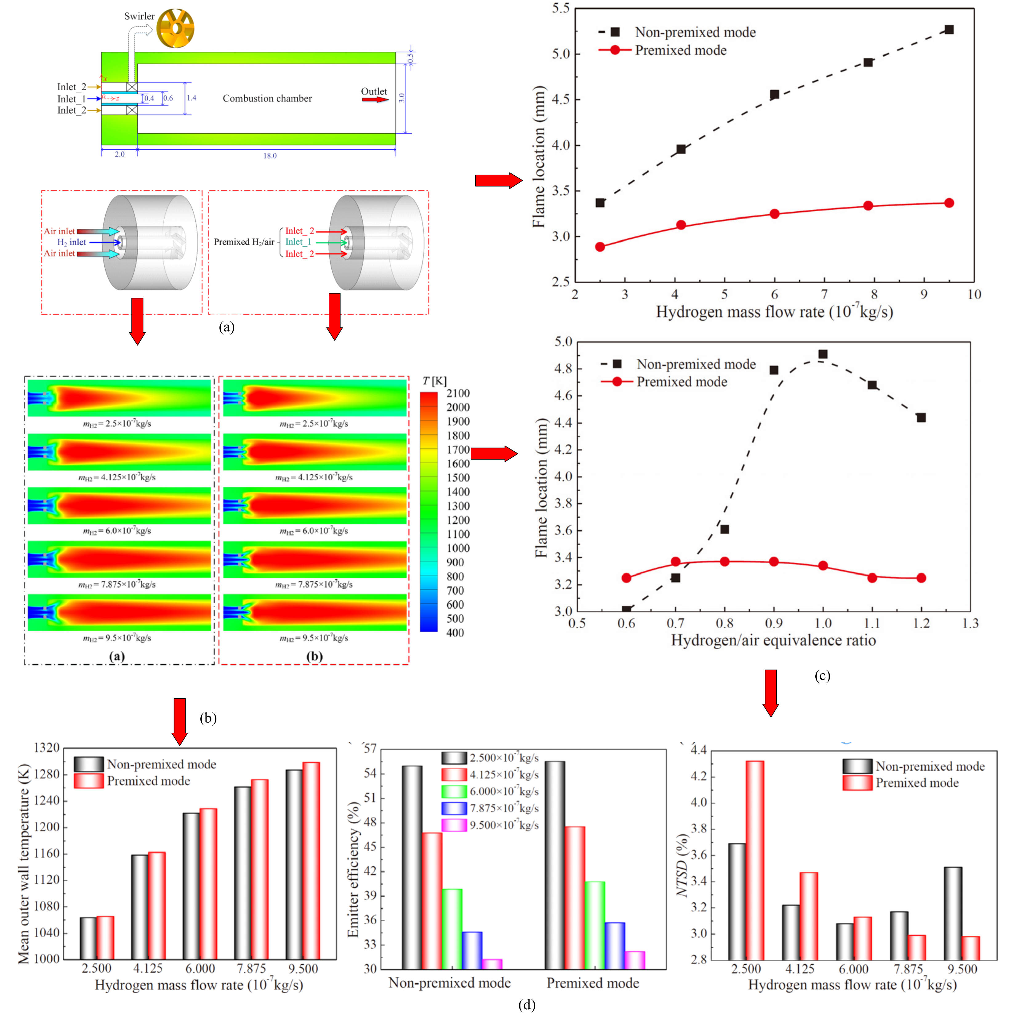
2. Effects of Non-Premixed and Premixed Condition

It is well known that there are differences in the flame characteristics between non-premixed and premixed combustion. Thus, it results in different thermal performance and heat-transfer mechanisms of the micro combustor. In addition, different fuels have different effects on the combustion. A systematic study on the influence of combustion mode is helpful to the practical application and design. So, this section introduces the effects of the non-premixed condition or premixed condition on the combustion of different fuels.

2.1. Premixed Combustion

The premixed flame-propagating velocity is a function of heat and mass loss, adiabatic flame temperature, transport properties, and fuel oxidation chemistry [39]. Moreover, the propagating velocity has a unique value relative to the unburned mixture. In the combustion process, both the heat or radical loss also will reduce the velocity of the flame and sometimes the flame will even extinguish, finally resulting in the propagation limitation. In addition, the max. temperature and velocity of flame will increase, as some external energy is participated with flame. Thus, the flame will become stronger due to the participation of the excess enthalpy. The influences of radical and heat losses on the premixed flame propagation become stronger for micro-scale combustion. In the National University of Singapore, Chou et al. [39,40,41] carried out the experiments and investigated the combustion characteristic and how the fuel-flow rate and H2/air ratio would affect the combustion characteristic. The propagation and combustion regime limits for the conventional flame are changed strongly by the heat recirculation or thermal feedback on a large scale. They found that fuel flow rate and H2/air ratio had a great impact on the device efficiency.

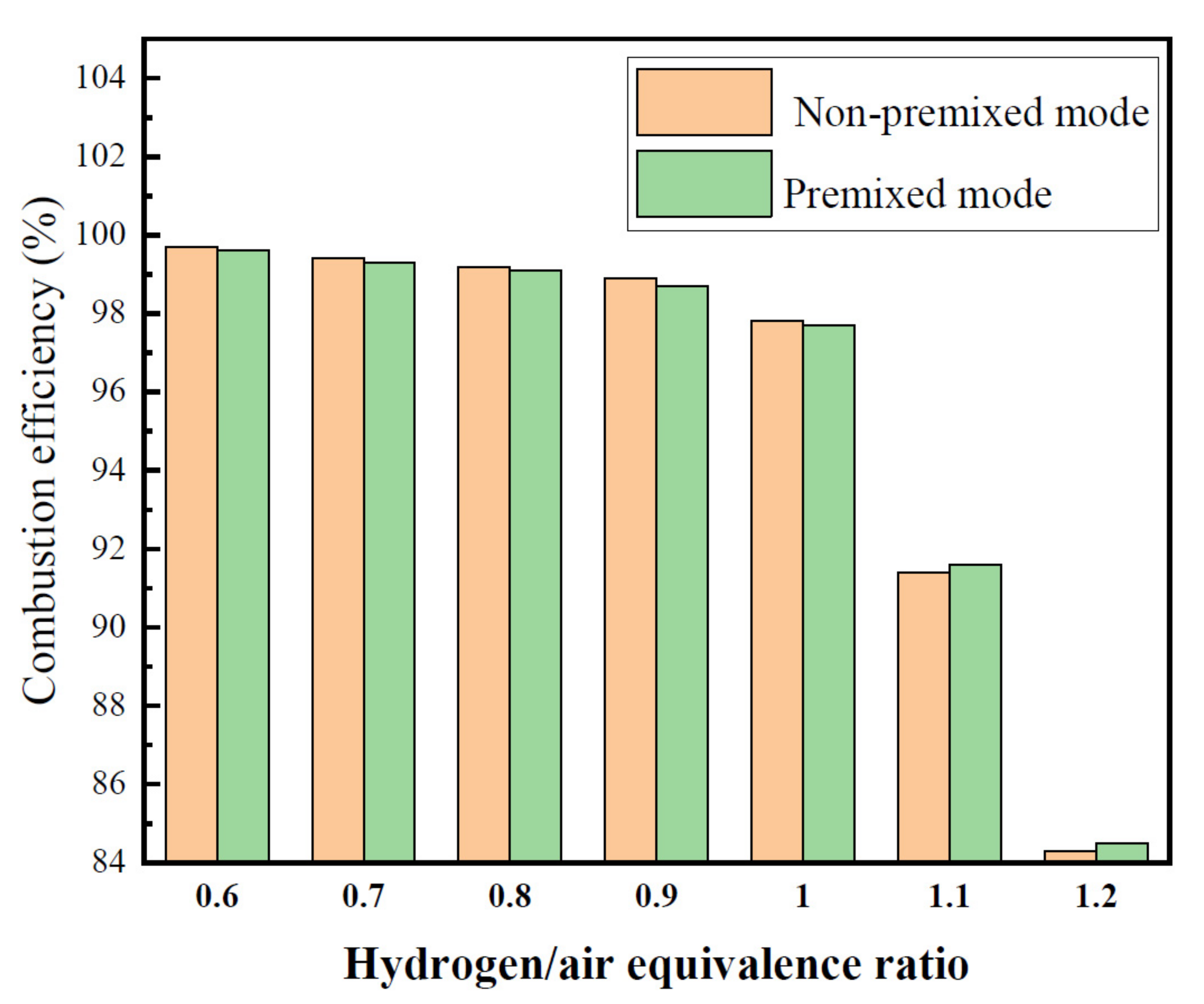
2.1.1. Effect of Fuel/Air Equivalence Ratio on Combustion Characteristics

Chou et al. carried out the experiments and investigated three different H2/air ratios (0.45, 0.7, and 1.0) on combustion characteristics [41]. In addition, the fuel-flow rate kept 8 ms−1 at the inlet. The micro-combustor proposed by Chou et al. and the combustion result are shown in Figure 3a–c. With the increase of H2/air ratios (0.45, 0.7, and 1.0), the combustion temperature increased.
For further study, Chou et al. [41] carried out a numerical simulation and the results are shown in Figure 3. The highest temperature (1305K) can be obtained in the micro-combustor chamber. Moreover, as the H2/air ratio was 1.0, and the combustor temperature showed a uniform distribution. Above all, the experimental result reported that the combustion completeness in the micro-combustor chamber can be improved by the increase of H2/air ratio. As shown in Figure 4, it can be found that with the increase of the H2/air ratio (0.15–0.9), the max. electrical power output increases continuously under different flow rate conditions. More fuel increases the released heat in the micro-combustor chamber. Subsequently, the combustor wall temperature increases greatly. However, the increase of the max. electrical power is very small as the H2/air ratio further continues to increase from 0.9 to 1.0.

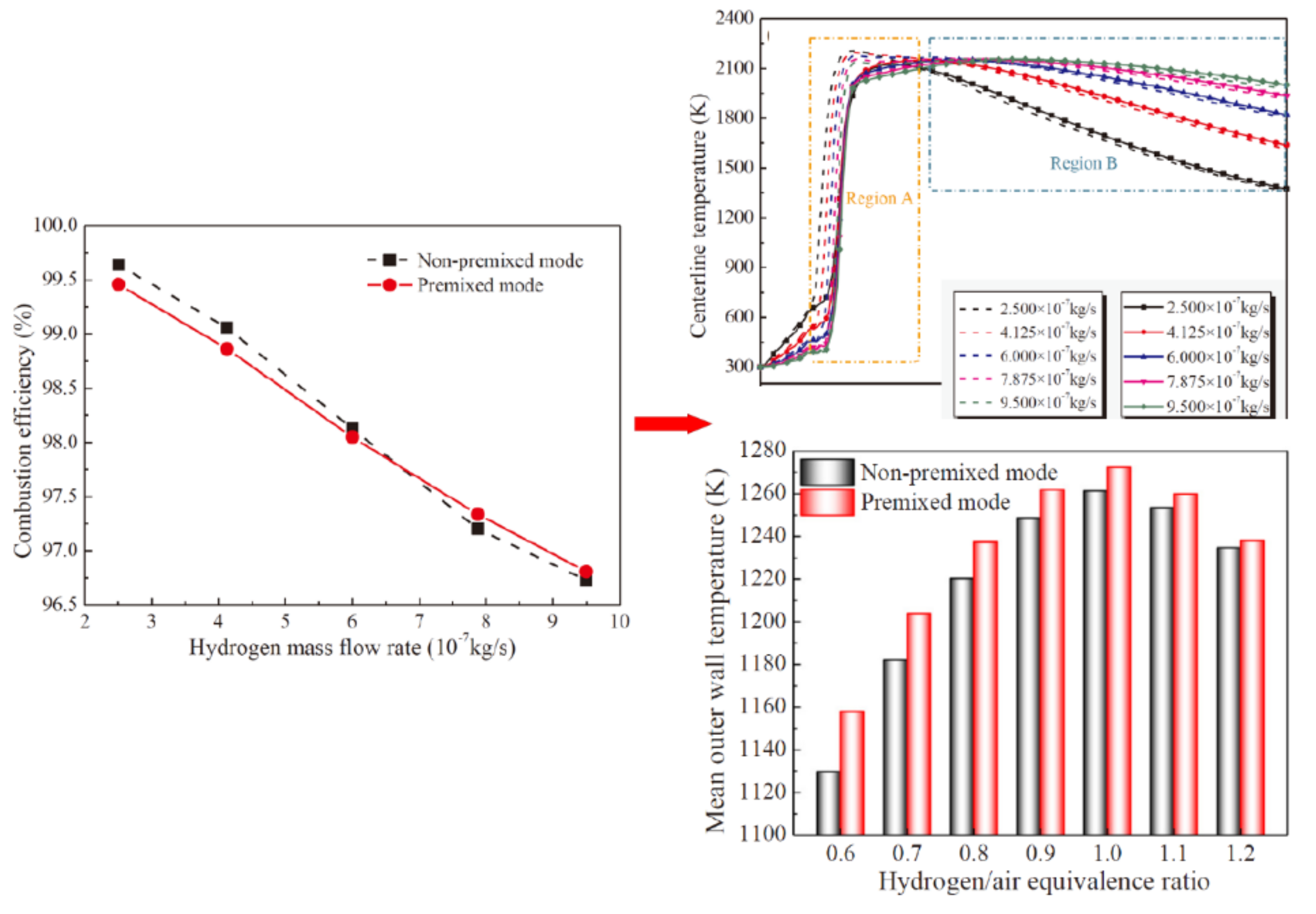
2.1.2. Effects of Mass Flow Rate on Combustion Characteristic

The effect of flow rate (Vin = 4 m/s−1, 8 m/s−1 and 12 m/s−1) on combustion characteristics based on the experiments were investigated by Chou et al. [41]. In the experimental process, the H2/air ratio was 0.6. The same micro-combustor proposed by Chou et al. was also employed to investigate the effect. Figure 4 shows the combustion result at different flow rates. It can be found that the wall color obviously changes when the fuel flow rate varies. In addition, the temperature in micro-combustor chamber increases as fuel flow rate increases. Above all, the maximum electrical power output increases with the increases of H2/air ratio and fuel flow rate. The increased flowrate improves the heat release rate, and subsequently increases the power output.

2.2. Non-Premixed Combustion

From the viewpoint of safety, the non-premixed combustion is more suitable for the micro-combustor application compared with premixed combustion. This is due to the fact that the flame flashbacks can be inhibited. Moreover, the improvement of the mixture of oxidizer and fuel is an important challenge of non-premixed combustion. In a Y-shaped non-premixed micro-burner, Miesse et al. found the multiple isolated flame cells [42]. The result showed that the multiple isolated flame cells would occur for heavier fuel, except for H2/O2 mixtures. In addition, Prakash et al. [43] investigated the non-premixed CH4/O2 combustion with the same configuration and found the transient flame dynamics, resulting in the formations of distinct cellular and stable edge flame structures. In addition, Xu and Ju [44] investigated the edge flame and isolated flamelets in a non-premixed CH4-air micro-scale burner. In the planar micro combustor, the diffusion combustion and mixing characteristics of H2-air were investigated by Li et al. [45]. In addition, based on the experimental investigation, the non-premixed CH4/air flames were divided into the edge flame mode and the premixed flame mode by Lee and Kim [46]. The liquid-fuel flame structure was investigated by Pham et al. [47] and the results showed that there were double flames, one triple flame located within the combustor chamber, and another anchored at the exit rim. Similarly, in the Y-shaped meso-scale combustors, Ning et al. carried out the experiments and investigated the non-premixed CH4/air flames when the combustor diameters were 4, 5, and 6 mm [48]. The results showed that after ignition, the flames were inclined and propagated downstream. In order to study the non-premixed combustion, Zuo et al. developed a micro elliptical tube combustor [49], they found that the flame could be maintained at with a very low equivalence ratio and very low fuel flow in this new burner.
In addition, based on the concept of swirl stabilization, a swirling combustor fueled with H2/air was developed by Xiao Yang et al. [39], as shown in Figure 5a–d. The results obtained show that the non-premixed is a high-flame location compared with the premixed. The flame position in the non-premixed is more vulnerable to the variations of equivalence ratio and H2/air mass.

2.2.1. Effects of Fuel/Air Equivalence Ratios on Combustion Characteristics

Figure 6 reports the combustion efficiency for the micro-combustor at the equivalence ratio (7.875 × 10⁻⁷ kg/s). With the increase of the H2/air equivalence ratio, the combustion efficiencies of premixed and non-premixed modes decrease in the micro combustors. With the increase of hydrogen/air equivalence ratio, the oxygen in mixture is reduced and the oxygen in the combustion chamber gradually becomes insufficient. Incomplete combustion occurs in the combustion chamber due to the lack of oxygen. Thus, it leads to a reduction in combustion efficiency. For example, it is 99.9% when the hydrogen/air equivalence ratio is 1.2 and the combustion efficiency is 84.1% when the hydrogen/air equivalence ratio is 1.2. Compared with the combustion efficiency of 0.6 equivalence ratio, the combustion efficiency of 1.2 equivalence ratio is decreased by about 16%.

2.2.2. Effects of Fuel Flow Rate

Figure 7 shows the combustion efficiency and temperature for micro-combustors. The result shows that when the H2 mass flow rate increases, the combustion efficiency will reduce under two operating modes. Similarly, the inlet speed increases when the H2 flow rate increases. Compared with the premixed combustor, the non-premixed combustor improves the combustion and increases combustion efficiency at lower hydrogen flow rates.

2.3. Comparison and Summary

Xiao Yang et al. [39] found that the H2/air equivalence ratio had a great impact on the combustor thermal characteristics. Due to the better thermal performance, it is strongly recommended to use a premixed combustor when the equivalent is low. As equivalence ratio increases, the difference is reduced.
Meanwhile, the flam position of non-premixed combustor is higher and more sensitive to the variations of equivalence ratio and H2/air flow rate compared with the premixed mode, as shown in Figure 5c. In addition, Figure 5d shows that the effects of H2 flow rate on thermal performance of outer wall. In addition, the wall temperature distribution of non-premixed mode is more uniform compared with the premixed mode at lower H2 flow rates, while the average outer wall temperature difference can be ignored. However, the wall temperature distribution is more uniform and higher than the non-premixed.
In the paper, the effects of the non-premixed and premixed on micro-combustion were mainly summarized, including the fuel mass flow rate and fuel/air equivalence ratio. Many simulations and experiments were carried out. Based on this knowledge, researchers could further investigate the effects of fuel type, fuel flow rate, and fuel/air equivalence ratio. Therefore, some adjustments and designs can improve the efficiency and stability.

3. Optimal Design of Combustor Geometrical Construction

Recently, the microscale combustion has made significant progress due to a huge number of experimental studies and numerical simulations. Many scholars have studied the basic characteristics of microscale combustion through simple geometric construction such as cylindrical, plate, and radial channel structures.
Zamashchikov [50], Mellish et al. [51], Miesse et al. [52], Prakash et al. [53], Yang et al. [54], and Wan et al. [55,56], researched some micro combustors with a basic construction such as cylindrical and plate through a series of experiments. The materials of the combustors are mainly stainless steel, high-temperature refractory ceramics, and quartz. The studies are significant to deepen the understanding of the basic physical problems of microscale combustion.
Meanwhile, numerical investigations are also used extensively in the research of the basic theory of micro combustion. Karagiannidis et al. [57], Norton [58], Hua et al. [59], Li et al. [60], Chen et al. [61], Wan et al. [62], and George P et al. [63] developed numerical models and investigated the thermal performance enhancement for micro combustors. The research results are summarized as follows: hydrogen or hydrocarbon fuel in the microscale combustion was feasible and combustor wall thermal cycle played an important role in continuous flame burning [64]; in addition, the combustor length, channel width, and wall thickness were important factors to ensure effective burning [65].
Therefore, it is necessary to optimize geometrical structures of micro combustors for researchers to improve the micro combustion performance [66]. In this section, the optimal design of combustor geometrical construction is presented.

3.1. Effect of Basic Geometrical Parameter on Combustion Characteristics

3.1.1. Effect of Wall Thickness

The effect of wall thickness on heat recirculation and heat loss rate is very obvious [67,68]. The thicker wall can increase heat transfer and improve the uniform temperature distribution. On the contrary, the thinner wall shows a steeper axial temperature gradient [69,70]. For the thinner wall, the transverse thermal resistance can be negligible [71]. However, in some numerical studies, the heat conduction along the walls cannot be ignored [72,73]. Moreover, the behavior of wall thickness is similar to that of wall thermal conductivity [74,75]. Therefore, the performance of the combustion chamber can be adjusted not only by selecting wall thickness, but also by appropriate materials.
Figure 8a,b [76] indicates the critical external heat transfer coefficient. The arrow is employed to show the heat transfer direction and movement direction. The inlet flow velocity can be adjusted by the flow rate and affects the residence time and power input. However, there is an optimal inlet flow rate to keep the good combustion stability. Whether qualitative or quantitative analysis, the inlet flow rate has a great impact on combustion stability. The stability curve shows a bell-shaped envelope at lower inlet flow rates. This is due to a tradeoff between heat recirculation and heat loss [70].
In general, the conversion and temperature will decrease when the external heat transfer coefficient increases [77]. The phenomenon will occur when lots of heat in the combustor is removed at a high rate [78,79], or coupled to a strong endothermic reaction [80,81]. On the contrary, if the micro-system is coupled to the external heat source [82] or is an adiabatic [83], the conversion will be improved at the expense of hot spots. Thus, material choice is very important for combustors. Figure 8c [76] shows the functional relationship between the thermal conductivity and critical external heat transfer coefficient. It can be found that the shaded region satisfies the material stability criteria and breakthrough. It also shows the attainable operating region. The complete conversion regime is delimited by the breakthrough line. When it is higher than the breakthrough line, the temperature is low, and the conversion is incomplete. On the contrary, when it is lower than the breakthrough line, the temperature is high, and the conversion is complete. In order to avoid extinction and blowout, the external heat transfer coefficient is employed to restrict in the window for catalytic combustion, as well as to keep material stability. Under the conditions of the low thin walls or wall thermal conductivities, the satisfied region is narrow. However, the operating region is greatly expanded when the materials of moderate and high wall thermal conductivities are used.

3.1.2. Effects of Combustor Length

Variation on the length of the combustion chamber directly leads to changes of the total area and residence time available for heat dissipation to the surroundings. The reaction zone is local, which leads to a reduction in combustion stability as the length of the combustion chamber increases. In the catalytic micro-combustion chamber, the combustion stability increases as the length of combustion chamber increases. This is because the reaction zone in the catalytic micro-combustion zone is relatively wide and may span the entire combustion chamber [84].
Figure 9a is a stability diagram of combustor. It shows that the length of the combustion chamber has a great impact on the detonation limit of high-insulating materials. Figure 9b is a stability diagram of the inlet velocity and critical external heat transfer coefficient. In the nominal combustor chamber, the inlet-based residence time was also shown. Shorter combustion chambers are more stable at lower inlet velocities. This is due to the wider extinguishing limit by reducing external heat loss. On the contrary, compared with short combustion chambers, the combustion of long combustion chambers is more stable, especially at high inlet velocities. This is due to the fact that the blowout restriction is extended, and a longer residence time is provided. However, the influence of the length of the combustion chamber on the stability of combustion was not significant for the wall thermal conductivity. Figure 9b [76] shows the max. wall temperature and conversion as a function of inlet velocity for combustion chamber lengths. Thus, the length of the burner has an important influence on the temperature and conversion rate.

3.2. Effect of Wall Material on Combustion Characteristics

Traditional materials such as aluminum, zinc, and copper do not fit for the manufacture of micro-burners. Materials with good heat resistance and thermal conductivity should be selected. In the study of Yan et al. [85], four materials (ferrochrome, copper, quartz glass, and corundum) were employed to manufacture the micro-burners. Table 2 shows the physical properties.

3.2.1. Effects of Wall Material on Thermal Performance

Thermal conductivity and preheating efficiency affect each other. Figure 10a-c shows temperature distributions in the reaction zones axis in the combustors with different wall materials [83].
From Figure 11a–d, it can be concluded that the reaction zone temperature will increase and the influence on the hot spots is more significant when the wall thermal conductivity reduces. The temperature distribution of the burner with copper baffle is improved, and the preheating effect is the best. In addition, the max. temperature of the burner with chromium-iron or copper baffles will further exceed the melting point of the material when the inlet velocity is low.
Similarly, Yang et al. [86] studied the influence of solid materials on the microtube combustor with convergent-divergent channels. The obtained results show that the material of SiC improves the thermal characteristic in the micro-combustion chamber.
The effects of solid materials on the efficiency are showed in Figure 11c [84]. The results show that average outer wall temperature of steel wall is higher compared with the SiC wall. In addition, emitter efficiency is the opposite. Compared with quartz and steel, SiC should be considered as the wall material. More specifically, emitter efficiency of SiC is improved by 5.6%.

3.2.2. Effects of Wall Material on Stable Combustion Limit

In the study [85], the influence of solid materials on the limitation of stable combustion was studied, as shown in Figure 10c. The research results show that the limitation of stable combustion with quartz glass baffle is small compared with others. It was found that the reaction zone temperature increases when wall thermal conductivity decreases. Similarly, the hot spots become more obvious due to the uneven heat loss caused by the reduced thermal conductivity. The max. temperature of the combustion chamber may exceed the melting point due to the low melting point of ferrochrome and copper. Thus, the inlet velocity cannot be too small. Although the temperature distribution of copper baffle is uniform, it has a better preheating effect on combustible gas. Therefore, it is very important to choose suitable materials to manufacture the micro-combustion chamber.

3.2.3. Effect of Wall Material on Free Radicals

The effect of wall reaction is mainly reflected in the vicinity of the wall. For the burner with four materials [85], the -OH coverage near the catalytic wall is: quartz glass < ferrochrome < corundum < copper. The heat released by the chemical reaction will be more uniformly and more quickly transferred downstream and upstream as the thermal conductivity increases. Moreover, the surface reaction is more active, the methane adsorption capacity of the wall surface is stronger, and along the x direction the coverage of -H and -OH decreases. At that time, the coverage rate of -OH on the wall becomes the highest with higher thermal conductivity.

3.3. Effect of Structural Improvement on Combustion Characteristics

In addition, many researchers have conducted many experimental studies and numerical simulations on the design of micro-combustion chambers. The aim was to improve the micro-TPV system. Some generalizations and introductions are as follows.

3.3.1. Cavity

A low-speed region can be provided by the cavity in the microchannel and is employed to stabilize the flame. It is due to the intermediate free radicals and residence time of fuel/air mixture caused by the cavity. Therefore, the cavity technology can usually be employed to improve the supersonic combustion stability [86,87]. However, there are few studies on the influence of cavities on slow flow combustion. Li et al. proposed a novel design concept and improved the enhancement of H2/CH4, CH4/CO, and H2/CO and blended fuels by catalyst segmentation and cavity technologies in a micro channel [88,89,90]. It was found that the existence of cavity can significantly expand the stable operation range in a wide inlet velocity range for micro-reactor. Fan and Wan et al. [91,92] investigated the effects of equivalent ratio, inlet velocity, and concave cavity length–depth ratio on the combustion characteristic of H2/air premixed gas. The obtained results show the extinction limitation reach 22 m/s when the equivalence ratio is 0.5 and the length-depth ratio is 4.0. In addition, Ran et al. [38] developed a numerical model and investigated the methane/air catalytic combustion in convex and concave cavity micro-combustion. The result shows that the max. conversion rate is 85.3% when the equivalence ratio is 1.0 and the max. extinction limit value is 16.5 m/s in the convex cavity micro-combustion.
(1)
Flame-anchoring mechanisms of micro cavity-combustors
Wan and Fan et al. [92,93,94] developed a numerical model and investigated the premixed H2/air flame-anchoring mechanisms. The result showed that the recirculation zone and low velocity were formed, and the flame anchorage position was close to the vertical cavity wall. However, the upstream inner wall gradually heated the entering gas. It resulted in the earlier initiation of chain reactions, as shown in Figure 12. Especially near the flame-anchoring zone, the reaction is very intense. Moreover, the preferential transport effects caused by the differences between the two-dimensionality of flow field and mass diffusivities of various species control the local equivalence ratio. Thus, the low velocity and recirculation zone are provided simultaneously by the cavity. Similarly, the cavity can provide a better heat recirculation effect.
(2)
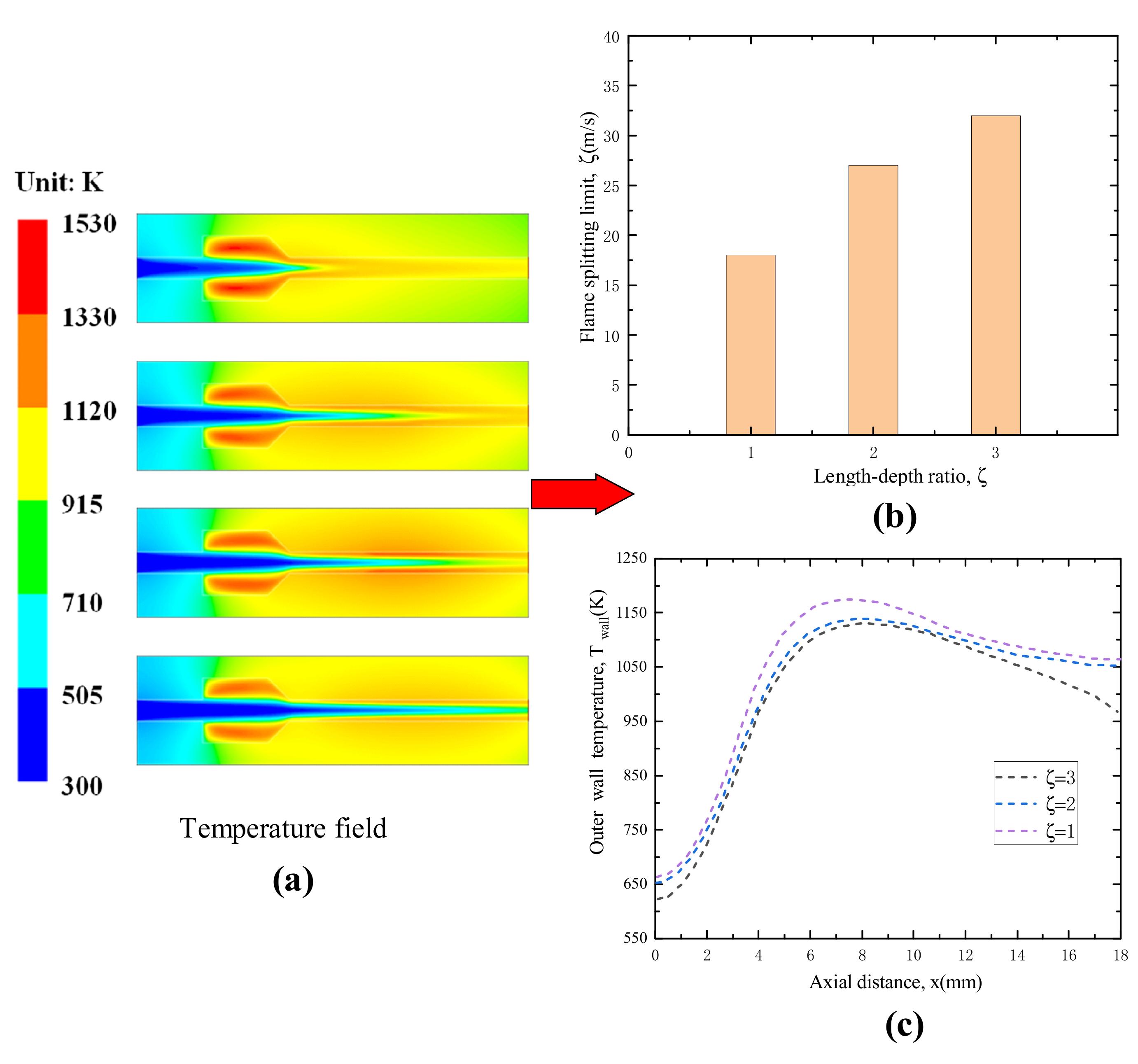
Effect of the depth and length of cavity
Wan and Wei et al. [91] investigated the effects of the cavity length-depth ratio. The results show that the larger the cavity length-depth ratio, the greater the flame splitting limit and the lower the wall temperature level. Thus, the large length-depth ratio is not beneficial to the improvement of combustion in micro-combustion chamber when the combustor wall is employed to be used as a thermal photovoltaic device or thermoelectric heat sources. In addition, the flame-splitting limit is showed in Figure 13a,b. The length-depth ratios have a great impact on the flame-splitting limit.
Figure 13c shows that the wall temperature level declines when the length-depth ratio increases. The large length-depth ratio of the cavity is not beneficial to the combustion in micro-combustion chamber when the combustor wall is employed to be used as a thermal photovoltaic device or thermoelectric heat source.
(3) Effect of the cavity aft ramp angle
Linhong L. et al. [95] investigated the effect of cavity aft ramp angle on the conversion ratio of lean H2/air combustion and the structure, as shown in Figure 14a. The results showed that the combustion efficiency of θ = 90° was high compared with θ = 135°, as the velocity was low, and the combustion efficiency of θ = 135° was high compared with θ = 90°, as the velocity was high. In addition, the flame height of θ = 90° was short compared with θ = 135°and the strain rate of θ = 90° was large compared with θ = 135°(see Figure 14b,c).
(4)
Effect of the cavity position
Zhang et al. [96] investigated the influence of cavity position on the catalytic combustion characteristic of CH4/air by the numerical method. The results showed that the variations of the positions of the convex cavity had little effect on CH4 conversion when inlet velocity was less than 1.0 m/s (see Figure 15a). In addition, when the convex cavity was located in the channel downstream, the methane conversion ratio and the extinction limit reached 85.6% and 18.3 m/s, respectively. As the inlet velocities of three channels are 4 m/s, average pressure and temperature on the inner surface along the channel are shown in Figure 15b,c. The pressure at the inlet of convex cavity increases sharply. As the convex cavity is located downstream of the channel, the outlet pressure reaches the max. value. Thus, it is more conducive to methane conversion.
Figure 15c shows the surface temperature when the inlet velocity is 3.0 m/s. As the mixtures flowed into the convex cavity, the fluid temperature rose rapidly. Similarly, the temperature gradually rose, and then reached a maximal value at the outlet. However, the variation of position of the convex cavity in the channel was less effective in comparison with the previous results.
(5) Effect of the channel gap distance
Wan and Fan et al. [97] numerically investigated the variation of the H2/air mixture flame splitting limit in micro channels with gap distance of wall cavities channel. The results indicate that the limits corresponding to 1.0 mm, 0.8 mm, and 0.6 mm channels are 26 m/s, 33 m/s, and 16 m/s respectively. The analysis shows that the fuel proportion which involves into the cavities increases, the flame length shortens at the same time, and the fresh mixture preheating effect is better when the gap distance decreases. When the distance was further decreased to 0.6 mm, the excessive stretching effect led to the complete extinction of downstream flame, resulting in the reduction of the splitting limit. In addition, the results show that the mechanism responsible for the largest flame splitting limit includes the good preheating effect of the fresh, mixture-large fuel proportion involved with the cavities, and reduced the length of the flame front. The over-stretching effect caused by the extinction of the downstream reaction zone is the main reason for the minimum splitting limit of the flame in the 0.6-mm channel.
(6) Double-cavity
Figure 16a shows the design features of combustor. The thermal performance of the double cavity combustor was numerically studied by Song et al. [98]. Figure 16b shows the temperature field of the micro-TPV system. Results show that the micro-TPV system needs a new combustor that obtains a more uniform and higher temperature distribution, and this new type of combustor is the highest temperature region formed in the down-stream chamber at a relatively high inlet velocity. The radiation efficiency of the double-cavity combustor and available radiation energy are higher than those of the single-cavity combustor. In addition, the results indicate that the inlet velocity determines the optimum cavity gap length.

3.3.2. Facing Step

The facing step provides a plain but valid way to strengthen the fuel mixing and lengthen residence time. It is very useful in controlling the position of flame and widening the ranges of the fuel/air ratio and flow rate [99]. The fluid strain and convergence are negative, because they are conducive to the flame stabilization. The thermal recirculation zone behind the steps provides an appropriate position.
(1)
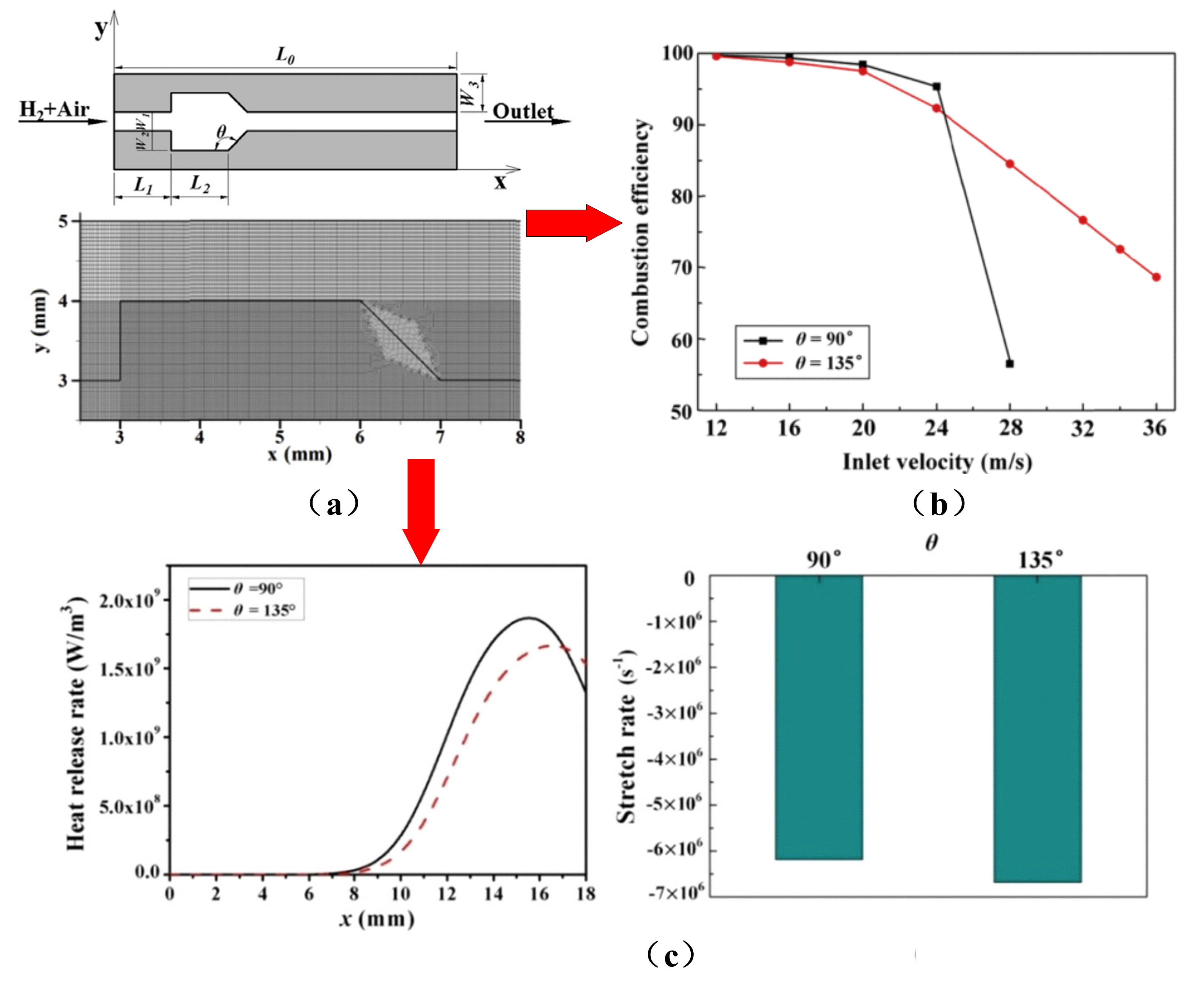
Effect of surface step on combustion characteristics
The flame position is considered to be the position of the max. value of the -OH radical mass fraction or the max. temperature gradient [99,100]. Hosein Faramarzpour et al. [101] simulated and developed a cylindrical combustor without and with a backward-facing step at different inlet velocities. The existence of the backward step leads to the increase of wall temperature and the blowout limit. The temperature distribution of micro-combustor is uniform along external wall. In addition, the lower the step height is, the higher the temperature is. At same inlet velocity, the temperature without backward facing step was about 50 K lower than that with the backward step. Meanwhile, by comparing the external wall of temperature distribution of the No. 2 combustor (the height of step is 1 mm) and the No. 3 combustor (the height of step is 2 mm), it was found that a large step height in combustor resulted in a lower temperature.
(2)
Effect of the cross-section types of steps
Saad et al. [102] investigated the energy conversion efficiency, pressure drop, wall-heat transfer, and wall temperature of a TPV with different cross-section types, such as trapezoidal, triangular, rectangular, square, and circular. Figure 17 shows that when the wall thickness, heat-transfer area, mass flow, and expansion ratio are the same, the outer wall temperature of triangular section is the highest. The increase of the square section temperature was the smallest, while that of triangular section was the largest [103]. This is due to the improved overall energy conversion efficiency caused by combustor geometry. The energy conversion efficiency increases by about 1% between the triangular and circular combustor.
(3)
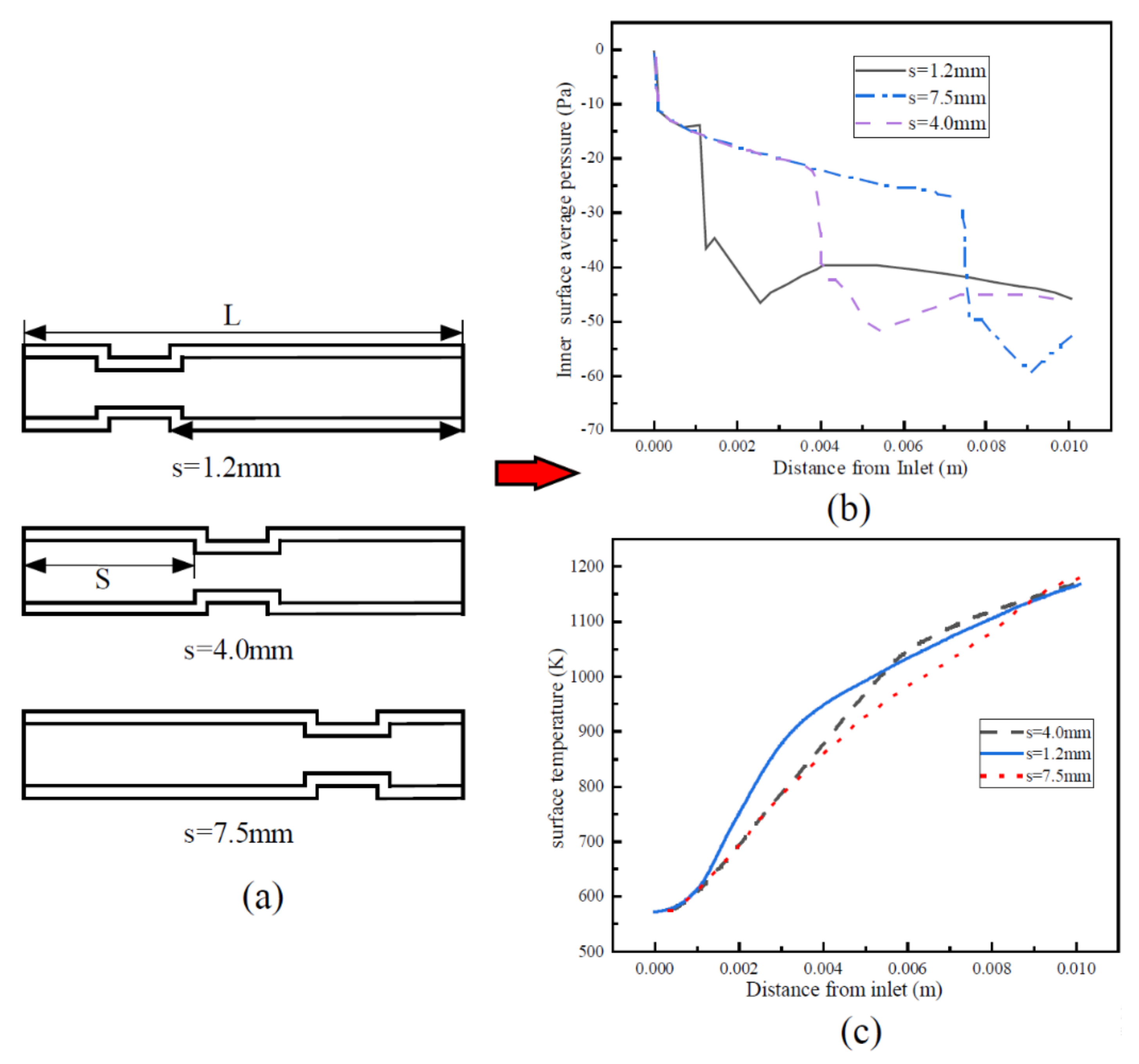
Effect of the step length and height
Peng et al. [104] investigated a combustor with various inlet shapes and two rearward-steps, as shown in Figure 18. They found that a shorter step length could improve the combustion and obtained a lower flame position and higher mean outer temperature in the micro-combustor system with a smaller outer diameter.
(4)
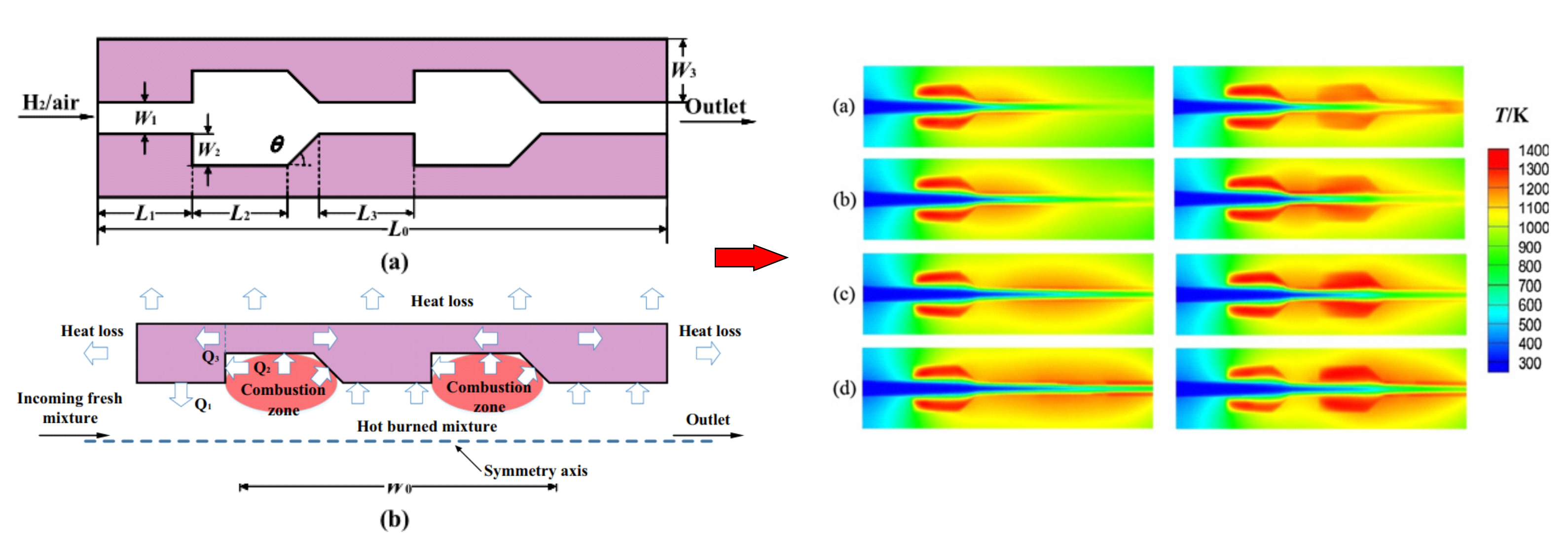
Effect of increase in the number of steps
The system efficiency and power output of the micro-combustor with two rear-ward steps are more than double compared with the micro-combustor with one step [104]. Additionally, E et al. [105,106,107,108] investigated the enhancement of micro-combustor with a step or two steps by numerical simulations. They found that inlet pressure had a great impact on specific entropy field, temperature, and velocity, especially at the regions of outlet and reaction. From the perspective of energy utilization, the system performed best at p = 0.1 MPa because it is possible to obtain higher exergy efficiency and better energy conversion efficiency. Bhupendra et al. [109] studied the effects of step number on flame stability limits. They chose a combustor with two steps (case 1) from previous work reported in Ref. [110] and designed a three-step configuration. The length of 30 mm and exit diameter of 6 mm were maintained constantly in a three-step (case 2) combustor compared with it (case 1).

3.3.3. Bluff Body

Bluff bodies are widely used in flame stabilization in propulsion and industrial combustion systems [111]. Combustion characteristics of micro-combustors with a bluff body were studied numerically and experimentally by many researchers.
(1)
Effect of blunt body on combustion characteristic
Wan et al. [112] conducted numerical and experimental studies on the combustion characteristic of lean H2/air mixture in blunt-body plane microchannels. They found that blow-off limits with a blunt body micro-combustor were significantly longer than those without a blunt body micro-combustor [113].
Furthermore, with the increase of inlet velocity, the flame front lengthens and narrows. In addition, the high-temperature section of the outer wall moves downstream. The exhaust gas temperature and combustion efficiency raise firstly and then reduce. They also studied the influence of solid materials on micro-combustor blow-off limits [113]. The result shows that at the same equivalence ratio and blockage ratio, the blow-off limit of quartz combustors is the largest, followed by stainless steel combustors and SiC combustors. The quartz combustors have the smallest blow-off limit. Thus, solid materials with low emissivity and thermal conductivity are beneficial to a great limit.
(2)
Effect of shapes of bluff body
Ghobad et al. [114] studied micro-combustor combustion characteristics with different shapes (ellipse, circle, triangle, semicircular, half ellipse, diamond, crescent, wall-blade, and arrowhead). Figure 19 shows the different micro-combustor flame structures. The results illustrate that in low velocity and a moderate equivalence ratio, the max. flame temperature occurs when a wall-blade is used. Meanwhile, Figure 19 shows the flow fields for different states. The micro-combustor flame with a wall-blade bluff body is more jarless than the others. Moreover, the micro-combustor average wall temperature with a wall-blade bluff body is the highest and the emitter efficiency is very high at low velocity.
(3)
Effects of blockage ratio
Fan et al. [115] investigated the influence of the blockage rate on the blow-off limit of a H2/air flame in a planar micro-combustor. The blow-off limit correlates positively with the blockage ratio. Yan et al. [116,117] studied the CH4/air combustion characteristic in a hollow hemispherical bluff body and a micro combustor with a regular triangular pyramid bluff body. Blockage ratio shows the great impact on flame stabilization and CH4 conversion. With the increase of the blockage ratio, the CH4 conversion firstly increased, and then reached the peak value when blockage ratio was 0.22, and finally decreased. Niu et al. [118] found that the two sides’ velocity difference between the bluff bodies became larger with the increase of blockage ratio. This is due to the formed whirlpools by the trapezoidal bluff bodies in a micro-channel.
(4)
Bluff body effect of two side slits
Yan et al. [119,120] constructed a micro combustor with slits on both sides of the bluff body and the bluff body was used to numerically study the effect of controllable flow angle on combustion characteristic and slit width. The effect of the controllable flow angle on combustion efficiency is shown in Figure 20.
They found that it was beneficial to prolonging the residence time in the reflux region and entraining more premixed gas, leading to the increase of efficiency and extinction limit of velocity. Meanwhile, appropriately reducing controllable slit width could enhance combustion efficiency. When the inlet velocity was 10 m/s and controllable slit width is 0.05 mm, the blow-off limit was the min. the and combustion efficiency was max. The change of controllable flow angle has an important effect on combustion efficiency. When controllable flow angle increased from 20° to 80°, the efficiency decreased by 7.26% and 11.62%.

3.3.4. Curved Micro-Combustor

Saad et al. [121,122] constructed a curved micro-combustor, as shown in Figure 21. They explored the effect of curvature on emission characteristics, hydraulic flame structure, and thermal properties. It was observed that the outer wall temperature for inner and outer sides was considerably higher than that of the straight duct, as shown in Figure 21. It resulted in an increase of heat flux, but the penalty must be paid in the form of increased NO emissions and pressure drop for curved combustors. Most studies on flow field for curved ducts and the heat transfer show that the dean vortices are the main reason for the enhancement of transport mass and thermal properties.

3.3.5. Flame Preheating and Holder Channels

Wan et al. [123,124] projected a micro combustor with a plate flame holder and preheating channels and investigated the effect of the plate length numerically on the CH4/air flame blowout limit. The results show the combustor flame blowout limits with different length flame holders. They found that for the lean fuel, a higher equivalence ratio resulted in a faster burning velocity and a higher preheating temperature. A higher preheating temperature further elevated the burning velocity as well as the flow speed of incoming gas mixture. The faster burning velocity made the flame shift upstream, but the bigger flow speed pushed the flame downstream. In such a way, the increase of equivalence ratio gives rise to the increase of burning velocity and flow speed, and the burning velocity increases faster than the flow speed.

3.3.6. Baffle

Jiang et al. [125,126] developed a micro-combustor with baffles and numerically and experimentally investigated the thermal performances and micro-combustor entropy generation distribution without and with baffles. Conventional micro-combustor and schematic diagrams are shown in Figure 22.
The temperature distribution of the combustor and conventional micro-combustor with baffles in the experiment is shown in Figure 22. They found that the average temperature of the conventional micro-combustors was lower than that of the combustor with baffles. For the combustors with baffles, the blowout limit was extended. Besides, the increased mean wall temperature can preheat the H2-air mixture by recovering heat from the exhaust gas. Meanwhile, a higher baffle resulted in larger breaking of available energy and more entropy.

4. Special Structure Combustor

In addition, the structure optimization of the microscale combustor should be described and summarized. Thus, many researchers have also designed micro combustors with unconventional structures and investigated the performances of them numerically and experimentally.

4.1. Swiss Roll Combustor

The Swiss-Roll type heat exchanger came from devices called heat-recirculating or excess enthalpy burners [127]. The flammability limits can be effectively extended by recirculating thermal energy from combusted products to preheat reactants. The reactants have increased total enthalpy due to the increased thermal enthalpy from preheating. The heat of combustor dissipation is effectively reduced by wrapping the heat exchanger in the Swiss-Roll configuration, and combustion in the core and heat transfer between windings become integral parts of the thermal system. This technology has recently reemerged due to efforts in micro scale combustion.
Zhong et al. [126,127,128] designed and manufactured three types of Swiss-roll combustors with double spiral-shaped channels, as shown in Figure 23. Results show that the Swiss-roll combustors highly increase the stability of combustion in the central area of the combustors.
Fan et al. [129] firstly proposed a micro-Swiss-roll combustor with a bluff-body, as shown in Figure 23. The results show that the flame blow-off limit can be greatly extended by reducing the flame stretching effect. The combustor had a larger blow-off limit, which was mainly attributed to the change in downstream flow field of the combustion chamber.
A miniature Swiss-roll combustor was manufactured by Wang et al. [130] for non-premixed combustion, as shown in Figure 23. The combustor has two inlets of CH4 and air and two outlets. They also found that a model combustor with a transparent quartz cover brought about several merits. Firstly, the outer wall temperature distribution and flame structure are symmetric. Secondly, the system can run even if the fuel flow rate and equivalence ratio are low.

4.2. New Special Structures

A new pattern micro planar combustor was proposed by Tang et al. [131], as shown in Figure 24a. The temperature distribution of the combustor center zone, wall temperature, and heat-transfer coefficient are shown in Figure 24b,c. They found that compared with a single-passage combustor, the new combustor reached a higher mean temperature due to the enhancement of heat transfer. Meanwhile, it developed more obvious due to the increased plate number. The heat transfer passage length has a great impact on the uniformity and mean wall temperature distribution. The setting up of parallel separating plates is beneficial for enhancing heat transfer.
Meanwhile, they investigated the effects of H2 to the premixed CH4-air mixture [132,133], as shown in Figure 25. It was found that the fuel blends with 30% CH4 and 70% H2 could improve the wall temperature, efficiency of combustion, and uniformity of temperature by 60 K, 4.5%, and 73%, respectively. Similarly, the proper H2 fraction depends on the thickness of the baffle and increases the energy input.
A micro-cylindrical combustor with gradually reduced wall thickness was proposed by Zuo et al. [134]. They numerically investigated the thermal performance. Results indicated that the emitter efficiency and outer micro combustor temperature with cylindrical channel were lower than that with gradually reduced wall thickness; additionally, there was more uniform temperature distribution of the gradually reduced wall thickness. Due to the diversity of flow channels in the micro combustor, the flow disturbance is caused, which promotes the convective heat transfer between the combustion gas and the wall. It can improve the thermal performance when it uses SiC as the wall material.

4.3. Multiple-Channel Micro Combustor

The total energy conversion efficiency is too low, which is one key problem. In order to solve this problem, the wall temperature and uniformity should be improved. However, the proposed multi-channel micro combustor can solve the problem well compared with the single-channel micro combustor.

4.3.1. Comparison of Single-Channel Combustors

A multiple-channel micro combustor was proposed by Su et al. [135]. At different flow rates, the temperature fields are shown in Figure 26. The results point out that the temperature distribution of the multiple-channel micro combustor is higher than that of the traditional micro combustor as well as more uniform, which is highly conducive to the micro-TPV system. Furthermore, the radiation energy and radiation efficiency of the single-channel micro combustor are lower than those of multiple-channel micro combustor. Tang et al. [131] utilized plate to divide a micro planar combustor into multiple-channel micro combustor. Results show that the new combustor could achieve a higher average temperature of the radiation wall caused by the improvement of heat transfer. Yilmaz et al. [136] realized that the input chemical energy conversion rate to utilizable heat energy could increase by nearly 30% more than that of the single-channel combustor when it had the multi-channel arrangement.

4.3.2. Effect of Different Configurations of Multiple-Channel Micro Combustor

E et al. [137,138] studied comparisons between co-flow and counterflow double-channel micro combustors numerically and improved the structure of the combustor. The schematic of two counterflow double-channel micro combustors is shown in Figure 27. As a result, the co-flow double-channel micro combustor had a less uniform outer wall temperature compared with that of the counterflow double-channel micro combustor. Moreover, the steel and silicon carbide could be used as the solid material of the combustor wall due to higher thermal conductivity.
Meanwhile, Zuo et al. [139] developed the inlets of traditional micro planar combustor into injectors so that it achieved higher thermal performance and output power. Schematic diagrams of two micro combustors are shown in Figure 27. In addition, with the help of fuel injector, the thermal performance of combustor was greatly improved. In the micro planar combustor, the inlet flow velocity was enhanced by the reduction of the step diameter.
The different configurations of a double-layer four-channel micro combustor and a four-channel planar combustor were investigated numerically by Zuo et al. [140,141]. They found that the wall temperature of micro combustor with double-channel four-channel was more uniform when there were more countercurrent channels in the adjacent channels on both sides of the double-channel four-channel micro combustor. Additionally, it was applicable for the four-channel planar combustor. They found that the wall temperature of the micro combustor with two-channel four-channel would be more uniform compared with a micro combustor with double-layer four-channel.

4.4. Summary

In this section, various important geometric structure optimization designs are summarized and compared. Many simulations and experimentations are introduced and analyzed. When there is a cavity in the microchannel, a low-speed region can be provided to stabilize the flame, resulting in enhancement of the intermediate free radicals of the fuel/air mixture and the increase of the residence time. In order to increase the mixing of fuel mixture and prolong the time of residence, a plain yet effective solution is proposed. This step is useful when the way comes to controlling flame position and expanding the operating range of flow and fuel/air ratio [103]. Bluff bodies are extensively used for flame stabilization in micro combustion. These optimization techniques, including their influencing factors, are recommended. It is observed that the straight tube combustor was significantly reduced compared with the curved micro combustor. Flame holder and preheating channels, and baffle are beneficial for reaching a higher wall temperature. Furthermore, the wall materials and thickness and combustor length are important design parameters which affect hot-spots, fuel efficiency, and burner stability strongly, as this section highlights.
Meanwhile, some special structure combustors are introduced. Swiss roll combustor can extend the flammability limits by recirculating thermal energy from combusted products to preheat reactants. A micro tube combustor with parallel separating plates, parallel baffles and cylindrical bluffs, and converging-diverging channels are introduced. It is shown that these combustors outperform the normal combustors in terms of the flame stability, wall temperature, emission, and efficiencies.
Moreover, the multi-channel micro combustor had better thermal performance. The effects of different configurations of multiple-channel micro combustors are also expounded.

4.5. Porous Media Micro Combustor

Porous media combustion has many advantages in combustion technology. The most interesting one of them is the possibility of achieving super adiabatic temperatures and ultra-lean combustion [142]. When porous media is used, it can improve heat transfer capacity and outer wall temperature so as to improve the effective radiant energy of the micro combustion chamber, which is conducive to the application of the micro TPV system. In this section, some generalizations and summarization about porous media used in the micro combustor are expounded.

4.5.1. Comparison of the Micro Combustor without and with Porous Medium

The solid matrix of porous media has higher conductivity, emissivity, and heat capacity than gas, so it can significantly improve the combustion in porous media [141]. There are a large number of channels or pores in the solid matrix of the porous medium. When passing through porous medium, these channels or pores heat the fresh reactant. Therefore, the thermal cycle mechanism from the combustion area to the fresh reactant gas increases the flame velocity, resulting in a higher heat release rate.
In a micro modular combustor, SiC porous media foam was designed by Yang et al. [143]. The methods improved the combustion and enhance heat transfer between the wall and hot gas, thereby increasing the wall temperature for the first time. The results indicate that the peak wall temperature increases by 90–120 K in SiC porous media. The increase of wall temperature obviously enhances radiation energy. Peng et al. [144,145] investigated the non-premixed and premixed H2-air combustion without and with porous medium. Results indicated that the flame stabilization is greatly enhanced when the combustor contains porous medium for both non-premixed and premixed combustion, as shown in Figure 28. In the combustor, the energy conversion and heat transfer from chemical energy to radiation power were effectively enhanced due to the insert of porous medium. In a planar micro-combustor, Chou et al. [146] used the channel width of 1 mm for researching the porous media combustion of premixed H2–air. Results showed that the wall temperature increases when the mixture velocities increase, and higher emitter efficiency was achieved for mixtures as the equivalence ratio was 0.8. In addition, the inserted porous media made the flames be found to be effectively fixed, despite the change of flow conditions. In summary, a huge number of research results suggested that the micro combustor packed by porous media can dramatically increase the wall temperature and flame stabilization, increasing the useful radiation energy of the micro combustor subsequently.

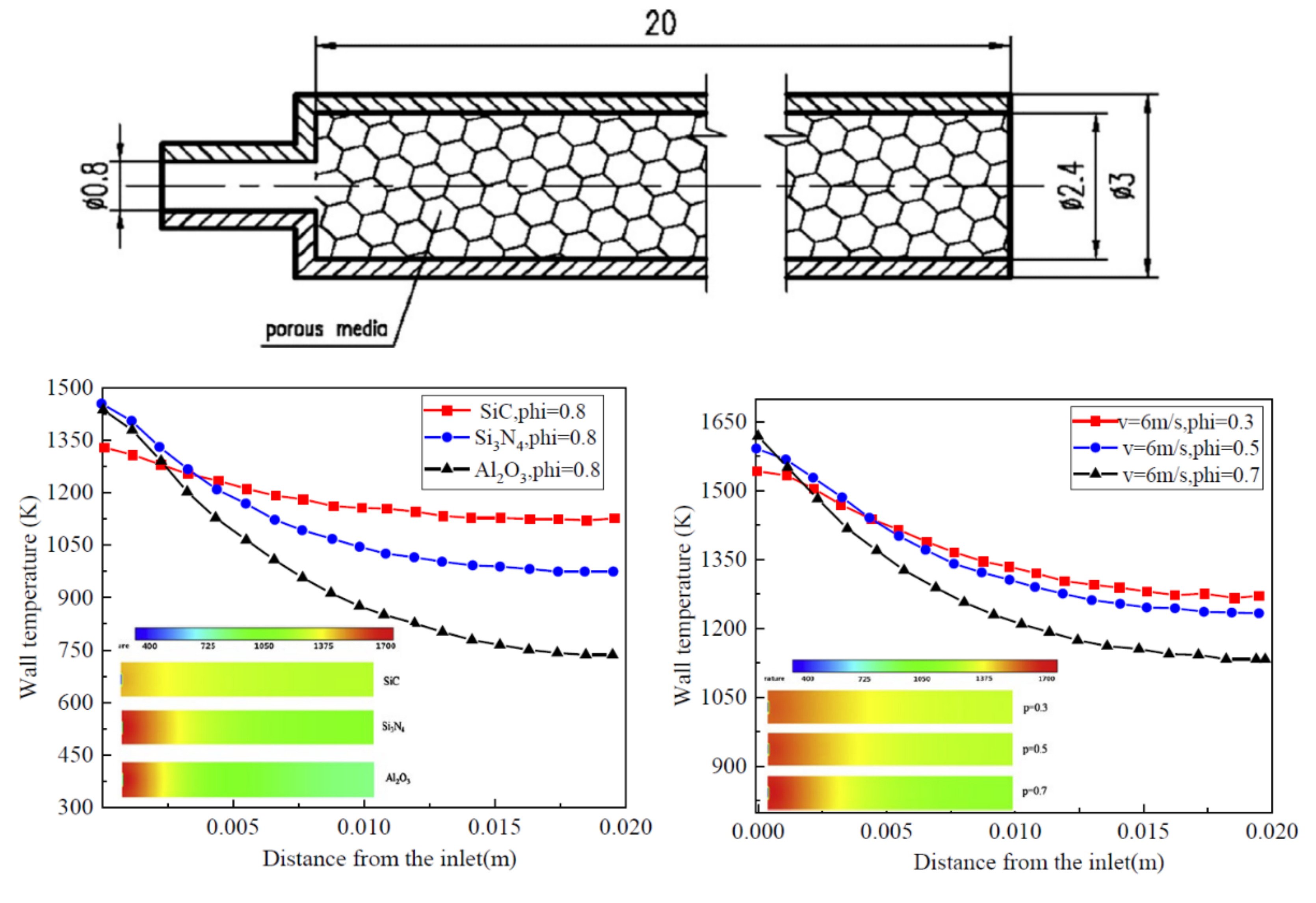
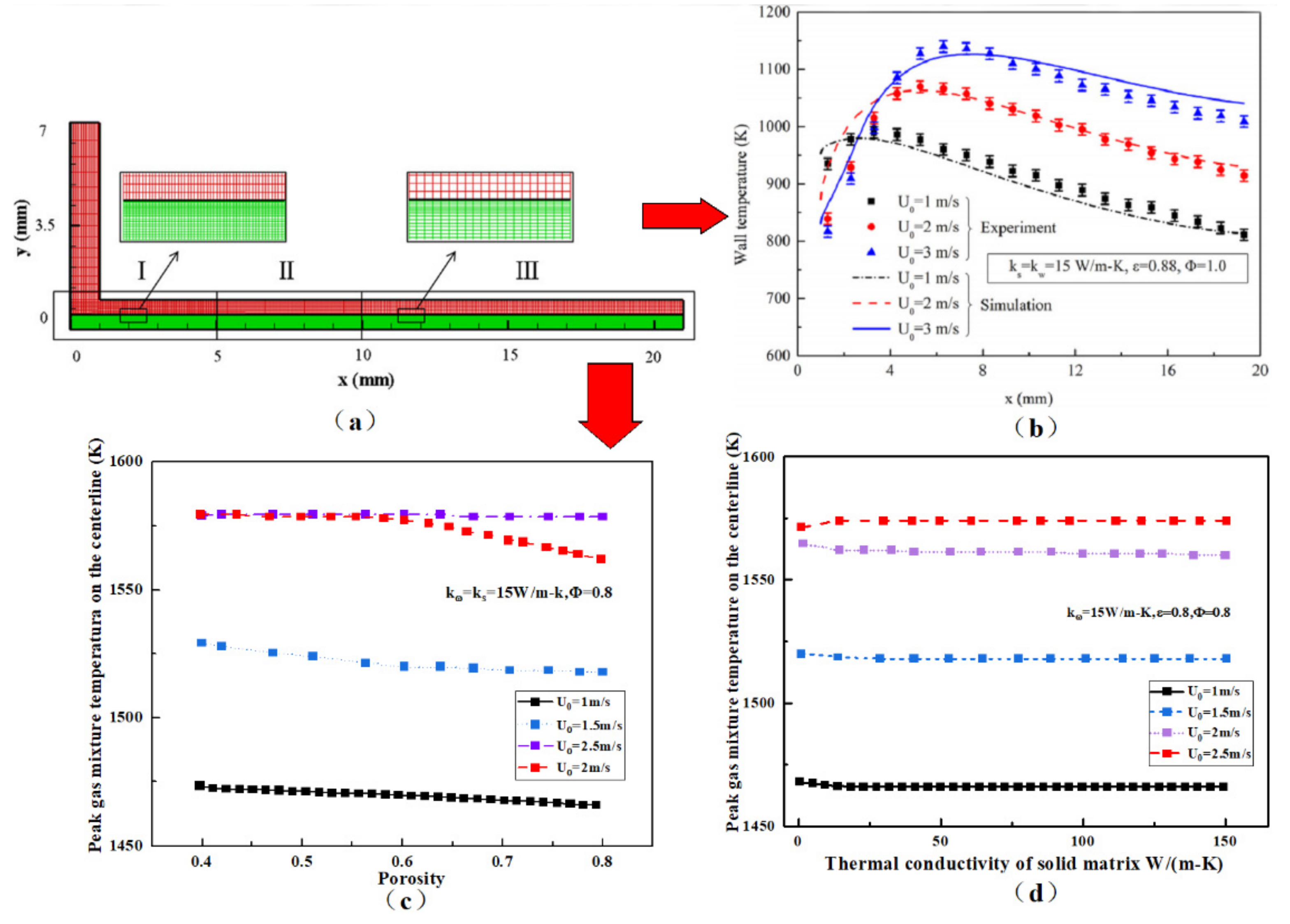
4.5.2. Effects of Properties of Porous Medium

Li et al. [147] studied the ratio of the thermal penetration time into the solid phase to the residence time in the pore. The heat conduction was the dominant mechanism within the porous media. The thermal conductivity and porosity of solid matrix are the most important factors affecting the wall temperature and heat transfer of porous combustion chamber. At the same time, the porous media material characteristic parameters are important factors, especially the Cp and thermoconductivity [148].
(1)
Effect of porous media porosity
Porosity has a critical effect on the thermal performance and flow field in the porous medium [149]. In the porous medium, the combustion with higher porosity has more space when the wall material has low heat conduction and radiation, which limit the improvement of heat transfer for the combustor. The flame stabilization weakens the preheating of reactants [150]. The radiative and convective heat transfer between the solid and fluid skeleton. Furthermore, thanks to a small combustion zone, the possibility of quenching on molecular collision and solid wall is increased.
Pan [148] found that porosity, when too small or large, would weaken the combustion process, and the combustion characteristic was impacted by porosity and other parameters impact together, as shown in Figure 29. When the mixture flow rate was (6 m/s), the temperature gradient was 251 K for the porosity of 0.3 and the average temperature along the combustion wall was 1387 K. It is obvious that the temperature gradient increases when the porosity increases.
Combustion in porous medium inserted in combustors experimentally was investigated by Peng et al. [145]. They found that the effect of porosity on wall temperature was enhanced when the combustion chamber size increased. The SS mesh volume increased when the porosity reduced. At a high mass flow, the mesh blowout and flame blowout may occur rate according to the experimental study.
Li et al. [151] numerically studied the heat recirculation in premixed H2/air filtration combustion in a planar micro-combustor, as shown in Figure 30. They found that Porosity (ε) and solid matrix thermal conductivity (ks) had significant effects on heat transfer in a porous micro-combustor, manifested by the variation of flame position and wall temperature distribution. The flame temperature seemed unaffected by the change of these two parameters.
(2)
Effect of porous media material
Due to the low Cp and high thermal conductivity of porous media material, the combustion will be intensified. Thus, the SiC was considered an ideal porous media material [152]. Figure 30 shows the micro combustor uniform temperature. The average wall temperatures for Si3N4, SiC, and Al2O3 materials are 1101 K, 1283 K, and 946 K, respectively. The average wall temperature for the case with SiC as the porous media is higher than the others. The flame temperatures of the Si3N4 and Al2O3 materials at the inlet of the micro combustor are higher than that of SiC material. The wall temperatures of the Si3N4 and Al2O3 materials drop slower than of SiC material in the back part of micro combustor.
Wang and Zuo et al. [153,154] investigated the flame characteristics of a propane/air mixture in a micro-scale porous combustor experimentally and numerically. They found that increase of wall thermal conductivity significantly improved the upper limits, but the effect on the lower limit was negligible. This is due to the fact that the higher wall thermal conductivity enhances the thermal cycle through the wall and porous media. When the same fuel energy is input, the outer-wall temperature increases due to the increase of the inner-wall convective heat-transfer coefficient. They also found that the gas temperature in the porous medium region increases significantly with the increase of wall thermal conductivity or inlet velocity in the stable operation range [155]. The heat loss ratio decreases when the inlet velocity or wall thermal conductivity increases.

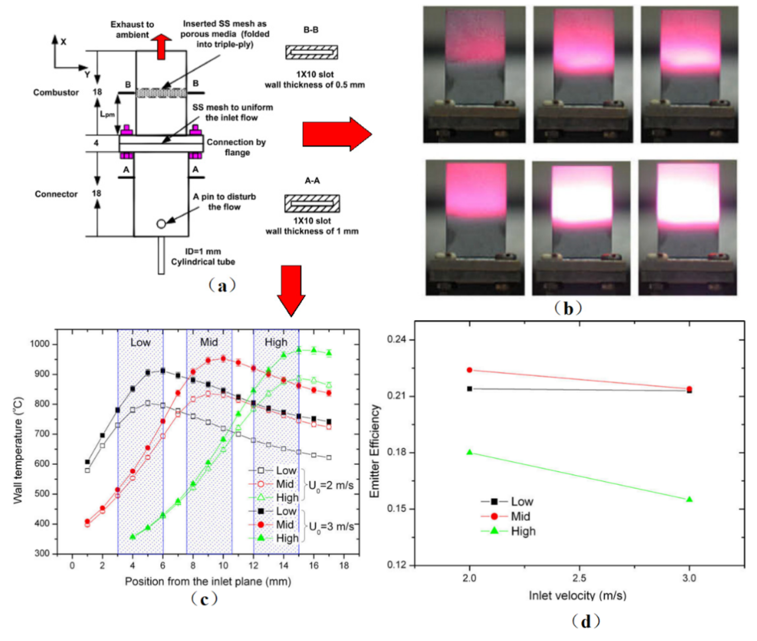
4.5.3. Effect of Filling Position and Folding Schemes

Figure 31a–d shows the influences of position of the porous media on the wall temperature and emitter efficiency [144]. The porous media were inserted into the channel with the positions from the inlet plane being 4.5, 9, and 13.5 mm, defined as ‘Low’, ‘Mid’, and ‘High’, respectively. It showed that the inserted porous media flames anchored effectively. When the porous media gets further from the combustor inlet, the peak wall temperature becomes higher. Additionally, based on the limited cases studied in their paper, the ‘Mid’ case represents a better emitter efficiency over the ‘Low’ and ‘High’ counterparts.
Meng et al. [156] studied the flame stability limits for premixed H2/air combustion when it was partially filled with porous medium. The porous medium was manually created from fine stainless steel mesh with a three-folding scheme to acquire the anisotropic properties. The results illustrate that the SB scheme represents a wider operation window than the other two counterparts under all experimental conditions studied, and this therefore provides some clues to the design as well as operation of porous micro combustors.

4.5.4. Summary

In this section, an overview of porous micro combustors is given. When the porous media is used in micro-combustors, they have great potential and improved efficiency. Many researchers studied the combustion properties. Both numerical and experimental studies showed that when extending standing-wave combustion, there were regimes in micro-combustors filled with porous medium [157]. Therefore, the potential mechanism affecting the critical flame stability limit is very important. In addition, some researchers are committed to designing new structures, such as a Y-type mesoscale combustion chamber with fibrous porous media [48]. In addition, micro-TPV system efficiency can be improved by thermal management [158,159], such as variation of the distance between the TPV cell and the combustor’s external surface.

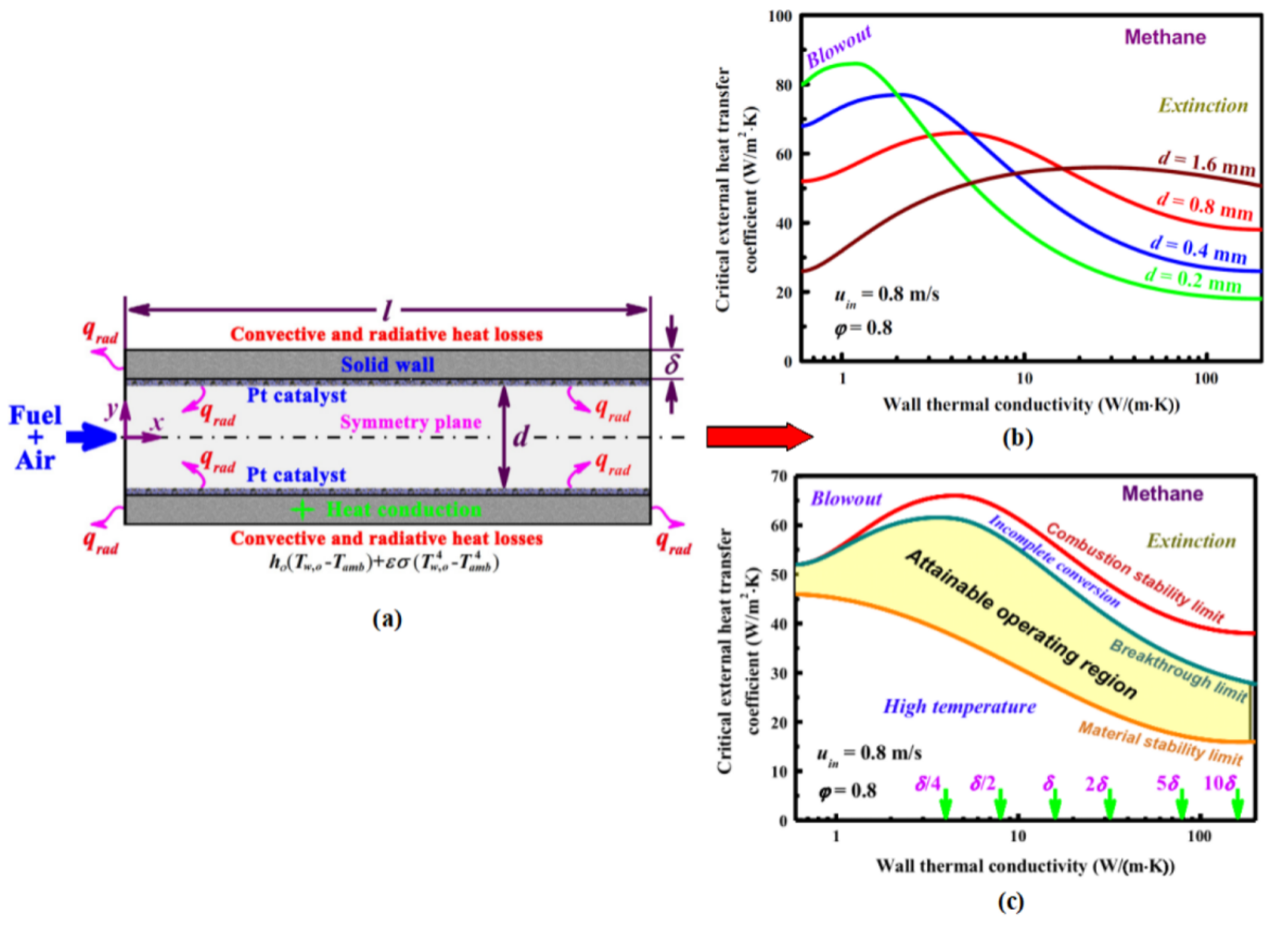
4.6. Catalytic Micro-Combustion

In ordinary large-scale applications, the thermal runaway is difficult to control. This weakness can be transformed into one of the important advantages for sustaining stable exothermic reactions, and the micro-combustor has the other advantages, such as no quenching distance, clean emission, moderate reaction temperature, and immobile heat release zone. In fact, proper heat management and reducing heat loss in catalytic micro burners are very important in homogeneous micro burners [160]. The reviews detail some new basic aspects of catalytic operation, design, combustion, and optimization, as well as the latest emphasized factors in micro-combustion applications.

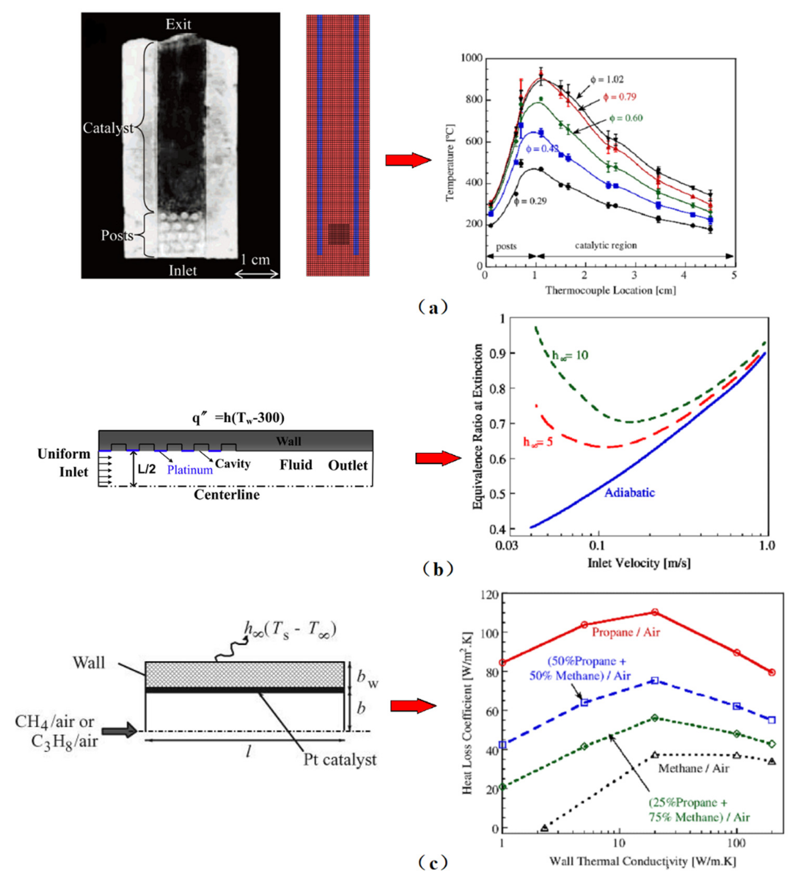
4.6.1. Combustion Characteristics

The residence time as well as the energy input into the system were determined by the bulk flow of reacting gases [161,162]. Reactants diffuse from the bulk gas to the wash coat, going into the porous support (catalyst layer) next. Within the support, reaction takes place on catalyst sites, and through the support products diffuse outwards and finally to the bulk gas. Since the micro burner solid structure has a thermal inertia and larger conductivity than the bulk gas, the walls were heated up by combustion reactions.
The catalytic micro burner can be divided into a post-reaction zone, a preheating zone, and a reaction zone. The reaction zones and preheating zones often overlap. The micro burner walls play a dual role: they act as a net heat sink in the post-reaction zones, and as a net heat source in the preheating/reaction zones.
For catalytic burners, gas-catalyst and mixing contact can be an issue [163]. Mixing can be enhanced by introducing a static structure near the inlet of the micro burner. Other alternatives adopt a careful design of inlet manifolds [164,165], a network of bifurcating channels [166], or a wire mesh at the inlet [167,168]. These are briefly reviewed in Deshmukh’s study [169].
Figure 32a shows the experimental axial temperature profiles in a Pt-catalyzed ceramic (alumina) micro burner. The micro burner’s initial section contains non-catalytic and staggered posts. Reactions take place mainly near the entrance because of the-H fast reaction on Pt. This area is associated with hot-spots due to the heat losses. With the increases of the equivalence ratio and inlet flow rate, the enthalpy input per unit micro burner volume increases, resulting in the increase of operating temperature (see Figure 32b,c). The reaction zone may be pushed downstream since it requires a longer length to heat up the increased gas flow. Results of catalytic combustion are reported in micro burner, including methane [170], hydrogen [171,172], methanol [173], propane [174], etc. In addition, catalytic combustion was been carried out [175,176,177,178].

4.6.2. Stability and Flammability Limits of Catalytic Combustion

Being associated with typical fundamental subjects of catalytic combustion, the USC combustion physics laboratory investigated the extinction limits of self-sustaining catalytic combustion by spiral counterflow Swiss-roll burners. They found that the combustion with a catalyst could be supported at much lower Re (minimum ≈1 vs. ≈40 without catalyst for our burner) and at extremely low temperatures (≈350 K vs. ≈920 K). This is due to the much lower effective activation energy. At the same time, with a catalyst, desorbing O(s) rich mixtures was an additional driving force [179].
Maruta et al. [180] studied the catalytic micro burner extinction limits by a cylindrical tube reactor. Figure 32b shows the extinction and blowout limits for methane/air combustion in a micro burner with thin wall approximation. It showed that the equivalence ratio at the extinction limit monotonically increases with the increase of inlet velocity while the wall boundary condition was adiabatic.
A pseudo 2D model was designed by Kaisare et al. [181] and employed to analyze the platinum-catalyzed micro burners. The optimal wall thermal conductivity value increases as the velocity increases. However, the micro burner stability increases monotonically when wall thermal conductivity increases and an optimum material for stability does not exist at very high velocities. In addition, when the mass-transfer rate increases the stability increases, and the stability in the wall conductivity range decreases when the heat-transfer rate from wall to fluid increases [182].
Micro-burner stability of a slow-burning fuel can improve mixing with a faster burning fuel [183]. It means that addition of hydrogen to propane and methane or addition of propane to methane can improve stability. Norton et al. evaluated a catalytic Pt-based micro device. It was found that hydrogen spontaneously combusts in a wide range of components and can successfully cause the spontaneous combustion of propane/air mixture in these micro burners, so there is no need to start the device. Thus, it is a good startup strategy that co-feeds hydrogen with propane. Yan et al. [184] investigated the combustion characteristic of H2 addition on catalytic micro-combustion systems. They found that hydrogen addition had a significant inhibition to CO and CO2 emissions and a significant impact on shortening ignition time and lowering the methane ignition temperature. The promotion effect of hydrogenation on combustion stability is due to the decrease in variation coefficient of hydrogenation, and this effect is stronger at low H2 fractions [185]. Meanwhile, as shown in Figure 32c, the temperature was elevated by the heat released on propane combustion and stabilized methane combustion.

4.6.3. Effect of Geometry

In order to study the impact of the cross-sectional geometry on the extinction/ignition behavior of catalytic micro combustors, Benedetto et al. [186] investigated two different shapes of the cross-section, circular and square. The results show that the square cross-section channel is more resistant to extinction than the cylindrical channel at low inlet velocities. Baigmohammadi et al. [187] numerically studied combustion characteristics of a micro reactor equipped with a catalytic bluff body. The results show that the flame stability can be significantly improved by using a catalytic bluff body in the center of the micro reactor, especially at high speeds. However, it can be found that it can improve the flame stability better than the catalytic bluff body with low thermal conductivity and no cavity when the surface of the catalytic bluff body has high thermal conductivity and multiple cavities. Li et al. [188,189] investigated the effect of catalyst segmentation on combustion performance and found that the existence of cavities appreciably extended the stable operational range of the micro combustor, as it had a wide range of inlet flow velocities. Moreover, the multi-segment catalyst with cavities appreciably extended the stable operating range of catalytic combustion in a small-scale combustor for a wide range of inflow velocities. Nevertheless, a gas-phase reaction could be sustained and anchored by the existence of cavity in a small-scale system. Ran et al. [190] numerically investigated catalytic combustion characteristics of methane in micro-channels with convex and concave cavities, severally, and in a straight channel without a cavity. It has been suggested that methane catalytic micro combustion was at a relatively low velocity when the micro-channel owned a concave wall cavity. In contrast, in a microchannel with a convex wall cavity, the pressure on the inner wall increases because the fuel breaks when flowing through the cavity. The contact between catalyst and methane mixture is enhanced, which is conducive to methane combustion.
In order to study the combustion stability of the catalytic thermal-recirculation micro combustor, several attempts were made. Chen et al. [191,192] investigated the combustion stability of premixed methane-air mixtures in heat recirculating micro combustors and catalytic single-channel. The results show that heat recirculation strongly affects blowout. It is worth mentioning that compared with other walls, the combustion chamber wall has a great impact on the stability. The combustion chamber wall has a highly insulated wall, which is the most stable system [193]. Therefore, the selection of wall thermal conductivity is of great significance. Thermal recirculation does not significantly improve stability, while thermal recirculation is only effective for low-conductivity walls and high-conductivity walls. With the decrease of wall thermal conductivity, the thermal recirculation effect becomes more obvious. Similarly, Yan et al. [194,195] also conducted a series of numerical studies to investigate combustion characteristics of catalytic heat-recirculating combustors. Due to the thermal cycle, the preheating channel plays a positive role in improving the combustion stability of the thermal cycle combustion chamber. The preheating channel is conducive to the thermal cycle effect, which leads to a significant increase in the specific enthalpy of methane at the outlet of the preheating channel. On the other hand, the preheating channel increases the catalyst surface temperature in the main reaction zone and promotes the adsorption of methane on the catalyst surface.

4.6.4. Effect of Wall Materials

Chen et al. [196] investigated three different wall materials. In their study, it was found that the wall thermal conductivity was lower when the wall temperature gradient was higher. The faster the homogeneous combustion moves upstream, the wider the temperature distribution range. Similarly, Chen et al. [197] investigated self-ignition characteristics of hydrogen and combustion in Pt/γ-Al2O3 catalytic micro combustors and also obtained the same conclusion. They found that when the wall thermal conductivity decreased, the time required to reach steady state reduced [198]. High-power systems require highly conductive materials. On the contrary, in order to minimize heat loss, low-power systems will tend to use more insulating materials [199]. It was believed that the heat loss had great influences on extinction and the wall thermal conductivity greatly affects blowout [200]. In addition, Li et al. [201] indicated that the increase of the wall thermal conductivity could increase the critical blowout velocity, suggesting the importance of operation of catalytic micro combustors and thermal management in the design.

4.6.5. Effect of Gap Size

In a catalytic micro combustor, there are two regions. The downstream region is dominated by the homogeneous combustion and upstream region is dominated by the heterogeneous reaction [196]. When the inlet velocity was boosted, the region dominated by heterogeneous reactions expanded downstream and occupied the whole combustor finally. When the flow rates were sufficiently low, the effect of gap distance was significant [199]. As the gap size increased, the critical blowout velocity decreased, and the micro combustor became more resistant [201]. The key factor of stable combustion is to select the appropriate combustion chamber size, because the limitations of material, stability, and conversion determine the rather narrow operation space. The optimum gap size depends on the flow rate or whether the flow rate remains constant [202].

5. Summary and Outlook

This review systematically introduces and summarizes the effect of different technologies on performance enhancement of the micro combustor for the micro thermophotovoltaic application in recent decades [203]. With the continuous deterioration of energy crisis [204,205,206,207,208,209,210] and environmental problems [211,212,213,214,215,216,217,218], finding effective methods to optimize the stable combustion of micro burners, and the integrated equipment of distributed and portable energy power generation has been demonstrated [219,220]. Based on the above review, the numerous experiments and numerical simulation mechanisms in the past decade are as follows:
(1)
Stabilizing combustion through heat recirculation, surface chemical treatment, and thermal management;
(2)
Different flame characteristics under different combustion condition (premixed and non-premixed), and the effects of fuel mass flow rate and fuel/air equivalence ratio;
(3)
Optimal design of combustor geometrical construction, the adjustment of the basic geometrical parameter and wall material, cavity, facing step, baffle, flame holder and preheating channels, curved micro-combustor, bluff body, some special structures, and multiple-channel micro combustor;
(4)
Combustion characteristics of porous media micro combustors and improvement;
(5)
Catalytic combustion in micro burners is reviewed and the role of key operation parameters is elucidated in this paper.
Although these developments are not yet fully mature, they have proved sufficient feasibility through technical challenges. The micro combustor for the micro TPV power system is a feasible and viable option with a bright future.
Meanwhile, there are still many works that can be carried out before it can be established for commercial applications. There are still many possibilities for improvement. Important directions of future research are likely to occur on several fronts:
(1)
Combined with low-temperature combustion technology, further optimization of the application of micro combustors will continue to be the focus of research;
(2)
Homogeneous, catalytic, homogeneous-heterogeneous, and excess enthalpy micro burners;
(3)
Coupled endo- and exothermic reactors for tapping unconventional energy sources, such as natural gas and biomass, will flourish;
(4)
High wall temperature and stable combustion can be achieved by new micro-combustors. Emitting power will be enhanced and it will improve the overall efficiency.

Author Contributions

Conceptualization, D.T. and S.C.; formal analysis, D.T., G.X., J.W., G.R., J.L. and Z.Z.; investigation, D.T., Y.H. and S.C.; resources, D.T. and S.C.; writing—original draft preparation, D.T. and S.C.; writing—review and editing, D.T. and S.C.; visualization, D.T., S.C. and Z.Z.; supervision, D.T. and S.C. All authors have read and agreed to the published version of the manuscript.

Funding

This research is supported by the Guangxi University of Science and Technology Doctoral Fund under the research grants of 20Z22, 20S04 and 21Z34; the work is supported by the Natural Science Foundation of Guangxi under the research grants of 2018GXNSFAA281267 and 2018 GXNSFAA 294072.

Institutional Review Board Statement

Not applicable.

Informed Consent Statement

Not applicable.

Data Availability Statement

All data used to support the findings of this study are included within the article.

Conflicts of Interest

The authors declare that they have no conflicts of interests regarding the publication of this paper.

References

  1. Zhao, D. Transient growth of flow disturbances in triggering a Rijke tube combustion instability. Combust. Flame 2012, 159, 2126–2137. [Google Scholar] [CrossRef]
  2. Yang, G.; Fan, A. Numerical study of an integrated miniature ejector for catalytic micro-combustors. Chem. Eng. Process.-Process Intensif. 2021, 160, 108295. [Google Scholar] [CrossRef]
  3. Cai, T.; Becker, S.M.; Cao, F.; Wang, B.; Tang, A.; Fu, J.; Han, L.; Sun, Y.; Zhao, D. NOx Emission performance assessment on a perforated plate-implemented premixed ammonia-oxygen micro-combustion system. Chem. Eng. J. 2021, 417, 128033. [Google Scholar] [CrossRef]
  4. Cai, T.; Zhao, D.; Wang, B.; Li, J.; Guan, Y. NOx emission and thermal performances studies on premixed ammonia-oxygen combustion in a CO2-free micro-planar combustor. Fuel 2020, 280, 118554. [Google Scholar] [CrossRef]
  5. Lee, S.J.; Chang, C.; Cha, S.W. Design and fabrication of a micro fuel cell array with “flip-flop” interconnection. J. Power Sources 2002, 112, 410–418. [Google Scholar] [CrossRef]
  6. Glatz, W.; Muntwyler, S.; Hierold, C. Optimization and fabrication of thick flexible polymer based micro thermoelectric generator. Sens. Actuators A Phys. 2006, 132, 337–345. [Google Scholar] [CrossRef]
  7. Cai, T.; Zhao, D. Effects of fuel composition and wall thermal conductivity on thermal and NOx emission performances of an ammonia/hydrogen-oxygen micro-power system. Fuel Process. Technol. 2020, 209, 106527. [Google Scholar] [CrossRef]
  8. Mehra, A.; Zhang, X.; Ayon, A.A.; Waitz, I.A.; Schmidt, M.A.; Spadaccini, C.M.; Microelectromech, J. A six-wafer combustion system for a silicon micro gas turbine engine. J. Microelectromech. Syst. 2000, 94, 517–527. [Google Scholar] [CrossRef]
  9. Cai, T.; Zhao, D.; Sun, Y.; Ni, S.; Li, W. Evaluation of NOx Emission Characteristics in a CO2-Free Micro-Power System by Implementing a Perforated Plate. Renew. Sustain. Energy Rev. 2021, 145, 111150. [Google Scholar] [CrossRef]
  10. Kaisare, N.S.; Vlachos, D.G. A review on micro combustion: Fundamentals, devices and applications. Prog. Energy Combust. Sci. 2012, 38, 321–359. [Google Scholar] [CrossRef]
  11. Zhang, Z.; Jiaqiang, E.; Deng, Y.; Pham, M.; Zuo, W.; Peng, Q.; Yin, Z. Effects of fatty acid methyl esters proportion on combustion and emission characteristics of a biodiesel fueled marine diesel engine. Energy Convers. Manag. 2018, 159, 244–253. [Google Scholar] [CrossRef]
  12. Du, L.; Shao, Y.; Sun, J. Advanced catalyst supports for PEM fuel cell cathodes. Nano Energy. 2016, 29, 314–322. [Google Scholar] [CrossRef] [Green Version]
  13. Kamarudin, S.K.; Daud, W.R.W.; Ho, S.L.; Hasran, U.A. Overview on the challenges and developments of micro-direct methanol fuel cells (DMFC). J. Power Sources 2007, 163, 743–754. [Google Scholar] [CrossRef]
  14. Zhao, T.S.; Xu, C.; Chen, R.; Yang, W.W. Mass transport phenomena in direct methanol fuel cells. Prog. Energy Combust. Sci. 2009, 35, 275–292. [Google Scholar] [CrossRef]
  15. He, W.; Zhang, G.; Zhang, X.; Ji, J.; Li, G.; Zhao, X. Recent development and application of thermoelectric generator and cooler. Appl. Energy 2015, 143, 1–25. [Google Scholar] [CrossRef]
  16. Tan, D.; Chen, Z.; Li, J.; Luo, J.; Yang, D.; Cui, S.; Zhang, Z. Effects of Swirl and Boiling Heat Transfer on the Performance Enhancement and Emission Reduction for a Medium Diesel Engine Fueled with Biodiesel. Processes 2021, 9, 568. [Google Scholar] [CrossRef]
  17. Ji, C.; Zhao, D. Two-dimensional lattice Boltzmann investigation of sound absorption of perforated orifices with different geometric shapes. Aerosp. Sci. Technol. 2014, 39, 40–47. [Google Scholar] [CrossRef]
  18. Yang, W.; Chua, K.; Pan, J.; Jiang, D.; An, H. Development of micro-thermophotovoltaic power generator with heat recuperation. Energy Convers. Manag. 2014, 78, 81–87. [Google Scholar] [CrossRef]
  19. Jiaqiang, E.; Ding, J.; Chen, J.; Liao, G.; Zhang, F.; Luo, B. Process in micro-combustion and energy conversion of micro power system: A review. Energy Convers. Manag. 2021, 246, 114664. [Google Scholar] [CrossRef]
  20. Zhang, Z.; Ye, J.; Tan, D.; Feng., Z.; Luo, J.; Tan, Y.; Huang, Y. The effects of Fe2O3 based DOC and SCR catalyst on the combustion and emission characteristics of a diesel engine fueled with biodiesel. Fuel 2021, 290, 120039. [Google Scholar] [CrossRef]
  21. Yang, W.; Chou, S.; Shu, C.; Xu, H.; Li, Z.W.; Li, D.T.; Pan, J.F. Microscale combustion research for application to micro thermophotovoltaic systems. Energy Convers. Manag. 2003, 44, 2625–2634. [Google Scholar] [CrossRef]
  22. Yang, W.; Chou, S.; Shu, C.; Xu, H.; Li, Z.W. Development of a prototype micro-thermophotovoltaic power generator. J. Phys. D Appl. Phys. 2004, 37, 1017–1020. [Google Scholar] [CrossRef]
  23. Zhao, D.; Li, X. A review of acoustic dampers applied to combustion chambers in aerospace industry. Prog. Aerosp. Sci. 2015, 74, 114–130. [Google Scholar] [CrossRef]
  24. Zhao, D.; Lu, Z.; Zhao, H.; Li, X.; Wang, B.; Liu, P. A review of active control approaches in stabilizing combustion systems in aerospace industry. Prog. Aerosp. Sci. 2018, 97, 35–60. [Google Scholar] [CrossRef]
  25. Ju, Y.; Kaoru, M. Microscale combustion: Technology development and fundamental research. Prog. Energy Combust. Sci. 2011, 37, 669–715. [Google Scholar] [CrossRef]
  26. Yang, W.; Chou, S.; Shu, C.; Xu, H.; Li, Z.W. Development of micro thermophotovoltaic system. Appl. Phys. Lett. 2002, 81, 5255–5257. [Google Scholar] [CrossRef]
  27. Yang, W.; Chou, S.; Shu, C.; Xu, H.; Li, Z.W. Design, fabrication, and testing of a prototype micro-thermophotovoltaic system. Microelectromech. Syst. 2004, 13, 851–856. [Google Scholar] [CrossRef]
  28. Hosseini, S.E.; Wahid, M.A. Investigation of bluff-body micro-flameless combustion. Energy Convers. Manag. 2014, 88, 120–128. [Google Scholar] [CrossRef]
  29. Lloyd, S.; Weinberg, F. A burner for mixtures of very low heat content. Nature 1974, 251, 47. [Google Scholar] [CrossRef]
  30. Weinberg, F.J. The first half-million years of combustion research and today’s burning problems. Prog Energ. Combust. 1979, 1, 17–31. [Google Scholar] [CrossRef]
  31. Jiaqiang, E.; Liu, G.; Zhang, Z.; Han, D.; Chen, J.; Wei, K.; Gong, J.; Yin, Z. Effect analysis on cold starting performance enhancement of a diesel engine fueled with biodiesel fuel based on an improved thermodynamic model. Appl. Energy 2019, 243, 321–335. [Google Scholar] [CrossRef]
  32. Kyritsis, D.C.; Guerrero-Arias, I.; Roychoudhury, S.; Gomez, A. Mesoscale power generation by a catalytic combustor using electrosprayed liquid hydrocarbons. Proc. Combust. Inst. 2002, 29, 965–972. [Google Scholar] [CrossRef] [Green Version]
  33. Kyritsis, D.C.; Roychoudhury, S.; McEnally, C.S.; Pfefferle, L.D.; Gomez, A. Mesoscale combustion: A first step towards liquid fueled batteries. Exp. Therm. Fluid Sci. 2004, 28, 763–770. [Google Scholar] [CrossRef]
  34. Gomez, A.; Berry, J.J.; Roychoudhury, S.; Coriton, B.; Huthl, J. From jet fuel to electric power using a mesoscale, efficient Stirling cycle. Proc. Combust. Inst. 2007, 31, 3251–3259. [Google Scholar] [CrossRef]
  35. Zhang, Z.; Jiaqiang, E.; Chen, J.; Zhu, H.; Zhao, X.; Han, D.; Zuo, W.; Peng, Q.; Gong, J.; Yin, Z. Effects of low-level water addition on spray, combustion and emission characteristics of a medium speed diesel engine fueled with biodiesel fuel. Fuel 2019, 239, 245–262. [Google Scholar] [CrossRef]
  36. Markatou, P.; Pfefferle, L.D.; Smooke, M.D. A computational study of methane-air combustion over heated catalytic and non-catalytic surfaces. Combust. Flame 1993, 93, 185–201. [Google Scholar] [CrossRef]
  37. Spadaccini, C.M.; Zhang, X.; Cadou, C.P.; Miki, N.; Waitz, I.A. Preliminary development of a hydrocarbon-fueled catalytic micro-combustor. Sens. Actuators A Phys. 2003, 103, 219–224. [Google Scholar] [CrossRef]
  38. Zuo, W.; Jiaqiang, E.; Liu, H.; Peng, Q.; Zhao, X.; Zhang, Z. Numerical investigations on an improved micro-cylindrical combustor with rectangular rib for enhancing heat transfer. Appl. Energy 2016, 184, 77–87. [Google Scholar] [CrossRef]
  39. Yang, X.; Zhao, L.; He, Z.; Dong, S.; Tan, H. Comparative study of combustion and thermal performance in a swirling micro combustor under premixed and non-premixed modes. Appl. Therm. Eng. 2019, 160, 114110. [Google Scholar] [CrossRef]
  40. Zhang, Z.; Jiaqiang, E.; Chen, J.; Zhao, X.; Zhang, B.; Deng, Y.; Peng, Q.; Yin, Z. Effects of boiling heat transfer on the performance enhancement of a medium speed diesel engine fueled with diesel and rapeseed methyl ester. Appl. Therm. Eng. 2020, 169, 114984. [Google Scholar] [CrossRef]
  41. Lu, Y.; Jiang, Z.; Geng, N.; Jiang, S.; Xie, X. Appointment Window Scheduling with Wait-Dependent Abandonment for Elective Inpatient Admission. Int. J. Prod. Res. 2021, 1977407. [Google Scholar] [CrossRef]
  42. Miesse, C.; Masel, R.I.; Short, M. Diffusion flame instabilities in a 0.75 mm non-premixed micro burner. Proc. Combust. Inst. 2005, 30, 2499–2507. [Google Scholar] [CrossRef]
  43. Prakash, S.; Armijo, A.D.; Masel, R.I. Shannon MA. Flame dynamics and structure within sub-millimeter combustors. AICHE J. 2010, 53, 1568–1577. [Google Scholar] [CrossRef]
  44. Ju, Y.; Xu, B. Studies on non-premixed flame streets in a mesoscale channel. Proc. Combust. Inst. 2009, 32, 1375–1382. [Google Scholar] [CrossRef]
  45. Li, L.; Yuan, Z.; Xiang, Y.; Fan, A. Numerical investigation on mixing performance and diffusion combustion characteristics of H2 and air in planar micro-combustor. Int. J. Hydrogen Energy 2018, 43, 12491–12498. [Google Scholar] [CrossRef]
  46. Lee, M.J.; Kim, N.I. The stabilization of a methane-air edge flame within a mixing layer in a narrow channel. Combust. Flame 2017, 157, 201–203. [Google Scholar] [CrossRef]
  47. Pham, T.K.; Dunn-Rankin, D.; Sirignano, W.A. Flame structure in small-scale liquid film combustors. Proc. Combust. Inst. 1997, 31, 3269–3275. [Google Scholar] [CrossRef]
  48. Ning, D.; Liu, Y.; Xiang, Y.; Fan, A. Experimental investigation on non-premixed methane/air combustion in Y-shaped meso-scale combustors with/without fibrous porous media. Energy Convers. Manag. 2017, 138, 22–29. [Google Scholar] [CrossRef]
  49. Zuo, W.; Jiaqiang, E.; Hu, W.; Jin, Y.; Han, D. Numerical investigations on combustion characteristics of H2/air premixed combustion in a micro elliptical tube combustor. Energy 2017, 126, 1–12. [Google Scholar] [CrossRef]
  50. Zamashchikov, V. Experimental investigation of gas combustion regimes in narrow tubes. Combust. Flame 1997, 108, 357–359. [Google Scholar] [CrossRef]
  51. Miller, F.J.; Dietrich, D.L.; Struk, P.; Tien, J.S.; Mellish, B.P. Premixed flames stabilized on or propagating inside microtubes. In Proceedings of the Fourth Joint Meeting of the US Sections of the Combustion Institute, Philadelphia, PA, USA, 23 March 2005; pp. 20–23. [Google Scholar]
  52. Miesse, C.M.; Masel, R.I.; Jensen, C.D.; Shannon, M.A.; Short, M. Submillimeter-scale combustion. AICHE J. 2004, 50, 3206–3214. [Google Scholar] [CrossRef]
  53. Zhang, Z.; Tian, J.; Li, J.; Ji, H.; Tan, D.; Luo, J.; Jiang, Y.; Yang, D.; Cui, S. Effects of different mixture ratios of methanol-diesel on the performance enhancement and emission reduction for a diesel engine. Processes 2021, 9, 1366. [Google Scholar] [CrossRef]
  54. Yang, W.; Chou, S.; Shu, C.; Li, Z.W.; Xue, H. Study of catalytic combustion and its effect on micro thermophotovoltaic power generators. J. Phys. D Appl. Phys. 2005, 38, 4252. [Google Scholar] [CrossRef]
  55. Wan, J.; Fan, A.; Liu, Y.; Yao, H.; Liu, W.; Gou, X.; Zhao, D. Experimental investigation and numerical analysis on flame stabilization of CH4/air mixture in a mesoscale channel with wall cavities. Combust. Flame 2015, 162, 1035–1045. [Google Scholar] [CrossRef]
  56. Wan, J.; Shang, C.; Zhao, H. Anchoring mechanisms of methane/air premixed flame in a mesoscale diverging combustor with cylindrical flame holder. Fuel 2018, 232, 591–599. [Google Scholar] [CrossRef]
  57. Karagiannidis, S. Hetero-/homogeneous combustion and stability maps in methane-fueled catalytic microreactors. In Catalytic Microreactors for Portable Power Generation; Springer: Berlin/Heidelberg, Germany, 2011; pp. 55–66. [Google Scholar]
  58. Norton, D.G.; Vlachos, D.G. A CFD study of propane/air micro flame stability. Combust. Flame 2004, 138, 97–107. [Google Scholar] [CrossRef]
  59. Hua, J.; Wu, M.; Kumar, K. Numerical simulation of the combustion of hydrogen–air mixture in micro-scaled chambers. Chem. Eng. Sci. 2005, 60, 3497–3506. [Google Scholar] [CrossRef]
  60. Li, J.; Chou, S.; Yang, W.; LI, Z.W. A numerical study on premixed micro-combustion of CH4–air mixture: Effects of combustor size, geometry and boundary conditions on flame temperature. Chem. Eng. J. 2009, 150, 213–222. [Google Scholar] [CrossRef]
  61. Chen, J.; Yan, L.; Song, W.; Xu, D. Effect of heat and mass transfer on the combustion stability in catalytic micro-combustors. Appl. Therm. Eng. 2018, 131, 750–765. [Google Scholar] [CrossRef]
  62. Wan, J.; Fan, A.; Yao, H. Effect of the length of a plate flame holder on flame blowout limit in a micro-combustor with preheating channels. Combust. Flame 2016, 170, 53–62. [Google Scholar] [CrossRef]
  63. Gauthier, G.P.; Watson, G.M.G.; Bergthorson, J.M. Burning rates and temperatures of flames in excess-enthalpy burners: A numerical study of flame propagation in small heat-recirculating tubes. Combust. Flame 2014, 161, 2348–2360. [Google Scholar] [CrossRef]
  64. Lu, Q.; Pan, J.; Yang, W.; Pan, Z.; Tang, A.; Zhang, Y. Effects of products from heterogeneous reactions on homogeneous combustion for H2/O2 mixture in the micro combustor. Appl. Therm. Eng. 2016, 102, 897–903. [Google Scholar] [CrossRef] [Green Version]
  65. Zuo, W.; Zhang, Y.; Li, Q.; Li, J.; He, Z. Numerical investigations on hydrogen-fueled micro-cylindrical combustors with cavity for micro-thermophotovoltaic applications. Energy 2021, 223, 120098. [Google Scholar] [CrossRef]
  66. Pan, J.; Huang, J.; Li, D.; Yang, W.; Tang, W.; Xue, H. Effects of major parameters on micro-combustion for thermophotovoltaic energy conversion. Appl. Therm. Eng. 2007, 27, 1089–1095. [Google Scholar] [CrossRef]
  67. Li, J.; Chou, S.; Li, Z.; Yang, W. Characterization of wall temperature and radiation power through cylindrical dump micro-combustors. Combust. Flame 2009, 156, 1587–1593. [Google Scholar] [CrossRef]
  68. Li, J.; Chou, S.; Huang, G.; Yang, W.; Li, Z. Study on premixed combustion in cylindrical micro combustors: Transient flame behavior and wall heat flux. Exp. Therm. Fluid Sci. 2009, 33, 764–773. [Google Scholar] [CrossRef]
  69. Norton, D.G.; Vlachos, D.G. Combustion characteristics and flame stability at the microscale: A CFD study of premixed methane/air mixtures. Chem. Eng. Sci. 2003, 58, 4871–4882. [Google Scholar] [CrossRef]
  70. Jiaqiang, E.; Cai, L.; Li, J.; Ding, J.; Chen, J.; Luo, B. Effects analysis on the catalytic combustion and heat transfer performance enhancement of a non-premixed hydrogen/air micro combustor. Fuel 2021, 309, 122125. [Google Scholar] [CrossRef]
  71. Wenming, Y.; Siawkiang, C.; Chang, S.; Hong, X.; Zhiwang, L. Effect of wall thickness of micro-combustor on the performance of micro-thermophotovoltaic power generators. Sens. Actuators A Phys. 2005, 119, 441–445. [Google Scholar] [CrossRef]
  72. Carroni, R.; Griffin, T.; Mantzaras, J.; Reinke, M. High-pressure experiments and modeling of methane/air catalytic combustion for power-generation applications. Catal. Today 2003, 83, 157–170. [Google Scholar] [CrossRef] [Green Version]
  73. Dogwiler, U.; Benz, P.; Mantzaras, J. Two-dimensional modelling for catalytically stabilized combustion of a lean methane-air mixture with elementary homogeneous and heterogeneous chemical reactions. Combust. Flame 1999, 116, 243–258. [Google Scholar] [CrossRef] [Green Version]
  74. Zhao, D.; Gutmark, E.; de Goey, P. A review of cavity-based trapped vortex, ultra-compact, high-g, inter-turbine combustors. Prog. Energy Combust. Sci. 2018, 66, 42–82. [Google Scholar] [CrossRef] [Green Version]
  75. Karagiannidis, S.; Mantzaras, J.; Boulouchos, K. Stability of hetero-/homogeneous combustion in propane- and methane-fueled catalytic microreactors: Channel confinement and molecular transport effects. Proc. Combust. Inst. 2011, 33, 3241–3249. [Google Scholar] [CrossRef]
  76. Chen, J.; Song, W. Optimal combustor dimensions for the catalytic combustion of methane-air mixtures in micro-channels. Energy Convers. Manag. 2017, 134, 197–207. [Google Scholar] [CrossRef]
  77. Stefanidis, G.D.; Vlachos, D.G. Intensification of steam reforming of natural gas: Choosing combustible fuel and reforming catalyst. Chem. Eng. Sci. 2010, 65, 398–404. [Google Scholar] [CrossRef]
  78. Stefanidis, G.D.; Vlachos, D.G. High vs. low temperature reforming for hydrogen production via microtechnology. Chem. Eng. Sci. 2009, 64, 4856–4865. [Google Scholar] [CrossRef]
  79. Wang, Y.; Zhou, Z.; Yang, W.; Zhou, J.; Liu, J.; Wang, Z.; Cen, K. Instability of flame in micro-combustor under different external thermal environment. Exp. Therm. Fluid Sci. 2011, 35, 1451–1457. [Google Scholar] [CrossRef]
  80. Zhou, J.; Wang, Y.; Yang, W.; Liu, J.; Wang, Z.; Cen, K. Improvement of micro-combustion stability through electrical heating. Appl. Therm. Eng. 2009, 29, 2373–2378. [Google Scholar] [CrossRef]
  81. Mettler, M.S.; Stefanidis, G.D.; Vlachos, D.G. Enhancing stability in parallel plate microreactor stacks for syngas production. Chem. Eng. Sci. 2011, 66, 1051–1059. [Google Scholar] [CrossRef]
  82. Yadav, S.; Yamasani, P.; Kumar, S. Experimental studies on a micro power generator using thermo-electric modules mounted on a micro-combustor. Energy Convers. Manag. 2015, 99, 1–7. [Google Scholar] [CrossRef]
  83. Singh, T.; Marsh, R.; Min, G. Development and investigation of a non-catalytic self-aspirating meso-scale premixed burner integrated thermoelectric power generator. Energy Convers. Manag. 2016, 117, 431–441. [Google Scholar] [CrossRef] [Green Version]
  84. Yan, Y.; Huang, W.; Tang, W.; Zhang, L.; Li, L.; Ran, J.; Yang, Z. Numerical study on catalytic combustion and extinction characteristics of premixed methane-air in micro flatbed channel under different parameters of operation and wall. Fuel 2016, 180, 659–667. [Google Scholar] [CrossRef]
  85. Zuo, W.; Li, Q.; He, Z.; Li, Y. Numerical investigations on thermal performance enhancement of hydrogen-fueled micro planar combustors with injectors for micro-thermophotovoltaic applications. Energy. 2020, 194, 116904. [Google Scholar] [CrossRef]
  86. Yang, X.; He, Z.; Dong, K.; Tan, H. Enhancement of thermal performance by converging-diverging channel in a micro tube combustor fueled by premixed hydrogen/air. Int. J. Hydrogen Energy 2019, 44, 1213–1226. [Google Scholar] [CrossRef]
  87. Gruber, M.R.; Donbar, J.M.; Carter, C.D.; Hsu, K.Y. Mixing and combustion studies using cavity-based flame holders in a supersonic flow. J. Propuls. Power 2004, 44, 769–778. [Google Scholar] [CrossRef]
  88. Nakaya, S.; Hikichi, Y.; Nakazawa, Y.; Sakaki, K.; Choi, M.; Tsue, M.; Kono, M.; Tomioka, S. Ignition and supersonic combustion behavior of liquid ethanol in a scramjet model combustor with cavity flame holder. Proc. Combust. Inst. 2015, 35, 2091–2099. [Google Scholar] [CrossRef]
  89. Wang, H.; Wang, Z.; Sun, M.; Zhang, S.; Wang, Z. Simulations of combustion with normal and angled hydrogen injection in a cavity-based supersonic combustor. Proc. Inst. Mech. Eng. G J. Aerosp. Eng. 2014, 228, 530–541. [Google Scholar] [CrossRef]
  90. Zhao, D.; Guan, Y.; Reinecke, A. Characterizing Hydrogen-fuelled pulsating combustion on thermodynamic properties of a combustor. Commun. Phys. 2019, 2, 44. [Google Scholar] [CrossRef] [Green Version]
  91. Wan, J.; Yang, W.; Fan, A.W.; Liu, Y.; Yao, H.; Liu, W.; Du, Y.; Zhao, D. A numerical investigation on combustion characteristics of H2/air mixture in a micro-combustor with wall cavities. Int. J. Hydrogen Energy 2014, 39, 8138–8146. [Google Scholar] [CrossRef]
  92. Yang, W.; Fan, A.; Yao, H. Effect of inlet temperature on combustion efficiency of lean H2/air mixtures in a micro-combustor with wall cavities. Appl. Therm. Eng. 2016, 107, 837–843. [Google Scholar] [CrossRef]
  93. Wan, J.; Fan, A. Recent progress in flame stabilization technologies for combustion-based micro energy and power systems. Fuel 2021, 286, 119391. [Google Scholar] [CrossRef]
  94. Wan, J.; Fan, A.; Yao, H.; Liu, W. Flame-anchoring mechanisms of a micro cavity-combustor for premixednH2/air flame. Chem. Eng. J. 2015, 275, 17–26. [Google Scholar] [CrossRef]
  95. Li, L.; Wei, Y.; Fan, A. Effect of the cavity aft ramp angle on combustion efficiency of lean hydrogen/air flames in a micro cavity-combustor. Int. J. Hydrogen Energy 2019, 44, 5623–5632. [Google Scholar] [CrossRef]
  96. Zhang, P.; Ran, J.; Li, L.; Du, X.; Qi, W.; Niu, J.; Yang, L. Effects of convex cavity structure, position and number on conversion of methane catalytic combustion and extinction limit in a micro-channel: A numerical study. Chem. Eng. Process. Process. Intensif. 2017, 117, 58–69. [Google Scholar] [CrossRef]
  97. Wan, J.; Fan, A.; Yao, H.; Liu, W.; Gou, X.; Zhao, D. The impact of channel gap distance on flame splitting limit of H2/air mixture in microchannels with wall cavities. Int. J. Hydrogen Energy 2014, 29, 11308–11315. [Google Scholar] [CrossRef]
  98. Su, Y.; Song, J.; Chai, J.; Cheng, Q.; Luo, Z.; Lou, C.; Fu, P. Numerical investigation of a novel micro combustor with double-cavity for micro-thermophotovoltaic system. Energy Convers. Manag. 2015, 106, 173–180. [Google Scholar] [CrossRef]
  99. Chou, S.; Yang, W.; Li, J.; Li, Z. Porous media combustion for micro thermophotovoltaic system applications. Appl. Energy 2010, 87, 2862–2867. [Google Scholar] [CrossRef]
  100. Alipoor, A.; Mazaheri, K. Studying the repetitive extinction-ignition dynamics for lean premixed hydrogen-air combustion in a heated microchannel. Energy 2014, 73, 367–379. [Google Scholar] [CrossRef]
  101. Faramarzpour, H.; Mazaheri, K.; Alipoor, A. Effect of backward facing step on radiation efficiency in a micro combustor. Int. J. Therm. Sci. 2018, 132, 129–136. [Google Scholar] [CrossRef]
  102. Akhtar, S.; Kurnia, J.C.; Shamim, T. A three-dimensional computational model of H2–air premixed combustion in non-circular micro-channels for a thermo-photovoltaic (TPV) application. Appl. Energy 2015, 152, 47–57. [Google Scholar] [CrossRef]
  103. Yang, W.; Chou, S.; Shu, C.; Li, Z.; Xue, H. Combustion in micro-cylindrical combustors with and without a backward facing step. Appl. Therm. Eng. 2002, 22, 1777–1787. [Google Scholar] [CrossRef]
  104. Peng, Q.; Wu, Y.; Jiaqiang, E.; Yang, W.; Xu, H.; Li, Z. Combustion characteristics and thermal performance of premixed hydrogen-air in a two-rearward-step micro tube. Appl. Energy 2019, 242, 424–438. [Google Scholar] [CrossRef]
  105. Jiaqiang, E.; Zuo, W.; Liu, X.; Peng, Q.; Deng, Y.; Zhu, H. Effects of inlet pressure on wall temperature and exergy efficiency of the micro-cylindrical combustor with a step. Appl. Energy 2016, 175, 337–345. [Google Scholar] [CrossRef]
  106. Zuo, W.; Jiaqiang, E.; Liu, X.; Peng, Q.; Deng, Y.; Zhu, H. Orthogonal Experimental Design and Fuzzy Grey Relational Analysis for emitter efficiency of the micro-cylindrical combustor with a step. Appl. Therm. Eng. 2016, 103, 945–951. [Google Scholar] [CrossRef]
  107. Jiaqiang, E.; Zuo, W.; Liu, X.; Peng, Q.; Deng, Y.; Zhu, H. Field synergy analysis of the micro-cylindrical combustor with a step. Appl. Therm. Eng. 2016, 93, 3–89. [Google Scholar] [CrossRef]
  108. Jiaqiang, E.; Liu, H.; Zhao, X.; Han, D.; Peng, Q.; Zuo, W.; Meng, T.; Qiu, R. Investigation on the combustion performance enhancement of the premixed methane/air in a two-step micro combustor. Appl. Therm. Eng. 2018, 141, 114–125. [Google Scholar] [CrossRef]
  109. Khandelwal, B.; Deshpande, A.A.; Kumar, S. Experimental studies on flame stabilization in a three tep rearward facing configuration based micro channel combustor. Appl. Therm. Eng. 2013, 58, 363–368. [Google Scholar] [CrossRef]
  110. Khandelwal, B.; Sahota, G.P.S.; Kumar, S. Investigations into the flame stability limits in a backward step micro scale combustor with premixed methane–air mixtures. J. Micromech. Microeng. 2010, 20, 095030. [Google Scholar] [CrossRef]
  111. Nair, S.; Lieuwen, T. Near-Blowoff Dynamics of a Bluff-Body Stabilized Flame. J. Propuls. Power 2007, 23, 421–427. [Google Scholar] [CrossRef]
  112. Wan, J.; Fan, A.; Maruta, K.; Yao, H.; Liu, W. Experimental and numerical investigation on combustion characteristics of premixed hydrogen/air flame in a micro-combustor with a bluff body. Int. J. Hydrogen Energy 2012, 37, 19190–19197. [Google Scholar] [CrossRef]
  113. Fan, A.; Wan, J.; Maruta, K.; Yao, H.; Liu, W. Interactions between heat transfer, flow field and flame stabilization in a micro-combustor with a bluff body. Int. J. Heat Mass Transf. 2013, 66, 72–79. [Google Scholar] [CrossRef]
  114. Bagheri, G.; Hosseini, S.E.; Wahid, M.A. Effects of bluff body shape on the flame stability in premixed micro-combustion of hydrogen–air mixture. Appl. Therm. Eng. 2014, 67, 266–272. [Google Scholar] [CrossRef]
  115. Fan, A.; Wan, J.; Liu, Y.; Pi, B.; Yao, H.; Maruta, K.; Liu, W. The effect of the blockage ratio on the blow-off limit of a hydrogen/air flame in a planar micro-combustor with a bluff body. Int. J. Hydrogen Energy 2013, 38, 11438–11445. [Google Scholar] [CrossRef]
  116. Yan, Y.; Yan, H.; Zhang, L.; Li, L.; Zhu, J.; Zhang, Z. Numerical investigation on combustion characteristics of methane/air in a micro-combustor with a regular triangular pyramid bluff body. Int. J. Hydrogen Energy 2018, 43, 7581–7590. [Google Scholar] [CrossRef]
  117. Zhang, L.; Zhu, J.; Yan, Y.; Guo, H.; Yang, Z. Numerical investigation on the combustion characteristics of methane/ air in a micro-combustor with a hollow hemispherical bluff body. Energy Convers. Manag. 2015, 94, 293–299. [Google Scholar] [CrossRef]
  118. Niu, J.; Ran, J.; Li, L.; Du, X.; Wang, R.; Ran, M. Effects of trapezoidal bluff bodies on blow out limit of methane/air combustion in a micro-channel. Appl. Therm. Eng. 2016, 95, 454–461. [Google Scholar] [CrossRef]
  119. Yan, Y.; Xu, F.; Xu, Q.; Zhang, L.; Yang, Z.; Ran, J. Influence of controllable slit width and angle of controllable flow on hydrogen/air premixed combustion characteristics in micro combustor with both sides-slitted bluff body. Int. J. Hydrogen Energy 2019, 44, 20482–20492. [Google Scholar] [CrossRef]
  120. Yan, Y.; He, Z.; Xu, Q.; Zhang, L.; Li, L.; Yang, Z.; Ran, J. Numerical study on premixed hydrogen/air combustion characteristics in micro-combustor with slits on both sides of the bluff body. Int. J. Hydrogen Energy 2019, 44, 1998–2012. [Google Scholar] [CrossRef]
  121. Akhtar, S.; Khan, M.N.; Kurnia, J.C.; Shamim, T. Numerical Investigation of H2-air Premixed Combustion in a Curved Micro-Combustor for Thermo-photovoltaic (TPV) Applications. Energy Procedia 2015, 75, 3060–3065. [Google Scholar] [CrossRef] [Green Version]
  122. Akhtar, S.; Khan, M.N.; Kurnia, J.C.; Shamim, T. Investigation of energy conversion and flame stability in a curved micro-combustor for thermo-photovoltaic (TPV) applications. Appl. Energy 2017, 192, 134–145. [Google Scholar] [CrossRef]
  123. Wan, J.; Zhao, H. Dynamics of premixed CH4 /air flames in a micro combustor with a plate flame holder and preheating channels. Energy 2017, 139, 366–379. [Google Scholar] [CrossRef]
  124. Wan, J.; Fan, A.; Yao, H.; Liu, W. Experimental investigation and numerical analysis on the blow-off limits of premixed CH4/air flames in a mesoscale bluff-body combustor. Energy 2016, 113, 193–203. [Google Scholar] [CrossRef]
  125. Jiang, D.; Yang, W.; Chua, K.J.; Ouyang, J. Thermal performance of micro-combustors with baffles for thermophotovoltaic system. Appl. Therm. Eng. 2013, 61, 670–677. [Google Scholar] [CrossRef]
  126. Jiang, D.; Yang, W.; Chua, K.J.; Ouyang, J.; Teng, J.H. Analysis of entropy generation distribution in micro-combustors with baffles. I Int. J. Hydrogen Energy 2014, 39, 8118–8125. [Google Scholar] [CrossRef]
  127. Tsai, B.J.; Wang, Y.L. A novel Swiss-Roll recuperator for the microturbine engine. Appl. Therm. Eng. 2009, 29, 216–223. [Google Scholar] [CrossRef]
  128. Zhong, B.; Wang, J.H. Experimental study on premixed CH4 /air mixture combustion in micro Swiss-roll combustors. Combust. Flame 2010, 157, 2222–2229. [Google Scholar] [CrossRef]
  129. Fan, A.; Zhang, H.; Wan, J. Numerical investigation on flame blow-off limit of a novel microscale Swiss-roll combustor with a bluff-body. Energy 2017, 123, 252–259. [Google Scholar] [CrossRef]
  130. Wang, S.; Yuan, Z.; Fan, A. Experimental investigation on non-premixed CH4 /air combustion in a novel miniature Swiss-roll combustor. Chem. Eng. Process. Process. Intensif. 2019, 139, 44–50. [Google Scholar] [CrossRef]
  131. Tang, A.; Pan, J.; Yang, W.; Xu, Y.; Hou, Z. Numerical study of premixed hydrogen/air combustion in a micro planar combustor with parallel separating plates. Int. J. Hydrogen Energy 2015, 40, 2396–2403. [Google Scholar] [CrossRef]
  132. Ansari, M.; Aman, E. Micro-combustor performance enhancement using a novel combined baffle-bluff configuration. Chem. Eng. Sci. 2018, 175, 243–256. [Google Scholar] [CrossRef]
  133. Amani, E.; Alizadeh, P.; Moghadam, R.S. Micro-combustor performance enhancement by hydrogen addition in a combined baffle-bluff configuration. Int. J. Hydrogen Energy 2018, 43, 8127–8138. [Google Scholar] [CrossRef]
  134. Zuo, W.; Jiaqiang, E.; Peng, Q.; Zhao, X.; Zhang, Z. Numerical investigations on thermal performance of a micro-cylindrical combustor with gradually reduced wall thickness. Appl. Therm. Eng. 2017, 113, 1011–1020. [Google Scholar] [CrossRef]
  135. Su, Y.; Cheng, Q.; Song, J.; Si, M. Numerical study on a multiple-channel micro combustor for a micro-thermophotovoltaic system. Energy Convers. Manag. 2016, 120, 197–205. [Google Scholar] [CrossRef]
  136. Yilmaz, H.; Cam, O.; Yilmaz, I. Effect of micro combustor geometry on combustion and emission behavior of premixed hydrogen/air flames. Energy 2017, 135, 585–597. [Google Scholar] [CrossRef]
  137. Zuo, W.; Jiaqiang, E.; Peng, Q.; Zhao, X.; Zhang, Z. Numerical investigations on a comparison between counterflow and coflow double-channel micro combustors for micro-thermophotovoltaic system. Energy 2017, 122, 408–419. [Google Scholar] [CrossRef]
  138. Zuo, W.; Jiaqiang, E.; Lin, M. Numerical investigations on an improved counterflow double-channel micro combustor fueled with hydrogen for enhancing thermal performance. Energy Convers. Manag. 2018, 159, 163–174. [Google Scholar] [CrossRef]
  139. Jiaqiang, E.; Zhao, X.; Qiu, L.; Wei, K.; Zhang, Z.; Deng, Y.; Han, D.; Liu, G. Experimental investigation on performance and economy characteristics of a diesel engine with variable nozzle turbocharger and its application in urban bus. Energy Convers. Manag. 2019, 193, 149–161. [Google Scholar] [CrossRef]
  140. Zuo, W.; E., J.; Han, D.; Jin, Y. Numerical investigations on thermal performance of double-layer four-channel micro combustors for micro-thermophotovoltaic system. Energy Convers. Manag. 2017, 150, 343–355. [Google Scholar] [CrossRef]
  141. Zuo, W.; E., J.; Lin, R.; Jin, Y.; Han, D. Numerical investigations on different configurations of a four-channel meso-scale planar combustor fueled by hydrogen/air mixture. Energy Convers. Manag. 2018, 160, 1–13. [Google Scholar] [CrossRef]
  142. Xu, K.; Liu, M.; Zhao, P. Stability of lean combustion in mini-scale porous media combustor with heat recuperation. Chem. Eng. Process. Process. Intensif. 2011, 50, 608–613. [Google Scholar] [CrossRef]
  143. Yang, W.M.; Chou, S.K.; Chua, K.J.; Li, J.; Zhao, X. Research on modular micro combustor-radiator with and without porous media. Chem. Eng. J. 2011, 168, 799–802. [Google Scholar] [CrossRef]
  144. Peng, Q.; Jiaqiang, E.; Chen, J.; Zuo, W.; Zhao, X.; Zhang, Z. Investigation on the effects of wall thickness and porous media on the thermal performance of a non-premixed hydrogen fueled cylindrical micro combustor. Energy Convers. Manag. 2018, 155, 276–286. [Google Scholar] [CrossRef]
  145. Peng, Q.; Yang, W.; Jiaqiang, E.; Xu, H.; Li, Z.; Yu, W.; Tu, Y.; Wu, Y. Experimental investigation on premixed hydrogen/air combustion in varied size combustors inserted with porous medium for thermophotovoltaic system applications. Energy Convers. Manag. 2019, 200, 112086. [Google Scholar] [CrossRef]
  146. Li, J.; Chou, S.; Li, Z.W.; Yang, W. Experimental investigation of porous media combustion in a planar micro-combustor. Fuel 2010, 89, 708–715. [Google Scholar] [CrossRef]
  147. Li, Z.; Chou, S.; Shu, C.; Yang, W. Effects of step height on wall temperature of a micro combustor. J. Micromech. Microeng. 2004, 15, 207–212. [Google Scholar] [CrossRef]
  148. Pan, J.; Wu, D.; Liu, Y.; Zhang, H.F.; Tang, A.K.; Xue, H. Hydrogen/oxygen premixed combustion characteristics in micro porous media combustor. Appl. Energy 2015, 160, 802–807. [Google Scholar] [CrossRef]
  149. Peng, Q.; Yang, W.; Jiaqiang, E.; Li, S.; Li, Z.; Xu, H.; Wu, G. Effects of propane addition and burner scale on the combustion characteristics and working performance. Appl. Energy 2021, 285, 116484. [Google Scholar] [CrossRef]
  150. Yang, H.; Minaev, S.; Geynce, E.; Nakamura, H.; Maruta, K. Filtration combustion of methane in high-porosity micro-fibrous media. Combust. Sci. Technol. 2009, 181, 654–669. [Google Scholar] [CrossRef]
  151. Peng, Q.; Yang, W.; Jiaqiang, E.; Li, Z.; Xu, H.; Fu, G.; Li, S. Investigation on H2/air combustion with C3H8 addition in the combustor with part/full porous medium. Energy Convers. Manag. 2020, 228, 113652. [Google Scholar] [CrossRef]
  152. Jiang, D.; Yang, W.; Liu, Y.J.; Liu, H.L.; Teng, J.H. The development of a wideband and angle-insensitive metamaterial filter with extraordinary infrared transmission for micro-thermophotovoltaics. J. Mater. Chem. C 2015, 3, 3552–3558. [Google Scholar] [CrossRef]
  153. Wang, W.; Zuo, Z.; Liu, J. Numerical study of the premixed propane/air flame characteristics in a partially filled micro porous combustor. Energy 2019, 167, 902–911. [Google Scholar] [CrossRef]
  154. Wang, W.; Zuo, Z.; Liu, J. Experimental study and numerical analysis of the scaling effect on the flame stabilization of propane/air mixture in the micro-scale porous combustor. Energy 2019, 174, 509–518. [Google Scholar] [CrossRef]
  155. Wang, W.; Zuo, Z.; Liu, J. The effect of wall thermal conductivity on the thermal performance of a partially filled micro porous combustor. Energy Procedia 2019, 158, 5188–5194. [Google Scholar] [CrossRef]
  156. Meng, L.; Li, J.; Li, Q.; Shi, J. Flame Stabilization in a Planar Micro combustor Partially Filled with Anisotropic Porous Medium. React. Eng. Kinet. Catal. 2017, 64, 153–160. [Google Scholar] [CrossRef]
  157. Li, Q.; Li, J.; Shi, J.; Guo, L. Effects of heat transfer on flame stability limits in a planar micro-combustor partially filled with porous medium. Proc. Combust. Inst. 2019, 37, 5645–5654. [Google Scholar] [CrossRef]
  158. Peng, Q.; Yang, W.; Jiaqiang, E.; Xu, H.; Li, Z.; Tay, K.; Zeng, G.; Yu, W. Investigation on premixed H2/C3H8/air combustion in porous medium combustor for the micro thermophotovoltaic application. Appl. Energy 2020, 260, 114352. [Google Scholar] [CrossRef]
  159. Bani, S.; Pan, J.; Tang, A.; Lu, Q.; Zhang, Y. Numerical investigation of key parameters of the porous media combustion based Micro-Thermophotovoltaic system. Energy 2018, 157, 969–978. [Google Scholar] [CrossRef]
  160. Jiaqiang, E.; Meng, T.; Chen, J.; Wu, W.; Zhao, X.; Zhang, B.; Peng, Q. Effect analysis on performance enhancement of a hydrogen/air non-premixed micro combustor with sudden expansion and contraction structure. Energy 2021, 230, 120727. [Google Scholar] [CrossRef]
  161. Kaisare, N.S.; Lee, J.H.; Fedorov, A.J. Hydrogen generation in a reverse-flow microreactor: 1. Model formulation and scaling. AICHE J. 2005, 51, 2254–2264. [Google Scholar] [CrossRef]
  162. Kaisare, N.S.; Stefanidis, G.D.; Vlachos, D.G.; Hessel, V.; Schouten, J.C.; Renken, A. Transport phenomena in microscale reacting flows. In Handbook of Micro Reactors: Fundamentals, Operations and Catalysts; Wiley: Hoboken, NJ, USA, 2009; Volume 1, pp. 283–302. [Google Scholar] [CrossRef]
  163. Norton, D.G.; Wetzel, E.D.; Vlachos, D.G. Fabrication of single-channel catalytic micro burners: Effect of confinement on the oxidation of hydrogen/air mixtures. Ind. Eng. Chem. Res. 2004, 43, 4833–4840. [Google Scholar] [CrossRef]
  164. Delsman, E.R.; Pierik, A.; Croon, M.H.J.M.D.; Kramer, G.J.; Schouten, J.C. Microchannel plate geometry optimization for even flow distribution at high flow rates. Chem. Eng. Res. Des. 2004, 82, 267–273. [Google Scholar] [CrossRef]
  165. Commenge, J.M.; Falk, L.; Corriou, J.P.; Matlosz, M. Optimal design for flow uniformity in microchannel reactors. AICHE J. 2002, 48, 345–358. [Google Scholar] [CrossRef]
  166. Amador, C.; Gavriilidis, A.; Angeli, P. Flow distribution in different microreactor scale-out geometries and the effect of manufacturing tolerances and channel blockage. Chem. Eng. J. 2004, 101, 379–390. [Google Scholar] [CrossRef]
  167. Deshmukh, S.R.; Vlachos, D.G. Novel micromixers driven by flow instabilities: Application to post-reactors. Chem. Eng. J. 2005, 51, 3193–3204. [Google Scholar] [CrossRef]
  168. Norton, D.G.; Wetzel, E.D.; Vlachos, D.G. Thermal management in catalytic microreactors. Ind. Eng. Chem. Res. 2006, 45, 76–84. [Google Scholar] [CrossRef]
  169. Federici, J.A.; Wetzel, E.D.; Geil, B.R.; Vlachos, D.G. Single channel and heat recirculation catalytic micro burners: An experimental and computational fluid dynamics study. Proc. Combust. Inst. 2009, 32, 3011–3018. [Google Scholar] [CrossRef]
  170. Boyarko, G.A.; Sung, C.J.; Schneider, S.J. Catalyzed combustion of hydrogen-oxygen in platinum tubes for micro-propulsion applications. Proc. Combust. Inst. 2005, 30, 2481–2488. [Google Scholar] [CrossRef]
  171. Mantzaras, J.; Bombach, R.; Schaeren, R. Hetero-/homogeneous combustion of hydrogen/air mixtures over platinum at pressures up to 10 bar. Proc. Combust. Inst. 2009, 32, 1937–1945. [Google Scholar] [CrossRef]
  172. Zhou, J.; Wang, Y.; Yang, W.; Liu, J.; Wang, Z.; Cen, K. Combustion of hydrogen-air in catalytic micro-combustors made of different material. Int. J. Hydrogen Energy 2009, 34, 3535–3545. [Google Scholar] [CrossRef]
  173. Reinke, M.; Mantzaras, J.; Schaeren, R.; Bombach, R.; Kreutner, W.; Inauen, A. Homogeneous ignition in high-pressure combustion of methane/air over platinum: Comparison of measurements and detailed numerical predictions. Proc. Combust. Inst. 2002, 29, 1021–1029. [Google Scholar] [CrossRef] [Green Version]
  174. Karim, A.M.; Federici, J.A.; Vlachos, D.G. Portable power production from methanol in an integrated thermoeletric/microreactor system. J. Power Sources 2008, 179, 113–120. [Google Scholar] [CrossRef]
  175. Ghermay, Y.; Mantzaras, J.; Bombach, R. Experimental and numerical investigation of hetero-/homogeneous combustion of CO/H2/O2/N2 mixtures over platinum at pressures up to 5 bar. Proc. Combust. Inst. 2011, 33, 1827–1835. [Google Scholar] [CrossRef]
  176. Zhang, Y.; Zhou, J.; Yang, W.; Liu, M.; Cen, K. Effects of hydrogen addition on methane catalytic combustion in a microtube. Int. J. Hydrogen Energy 2007, 32, 1286–1293. [Google Scholar] [CrossRef]
  177. Li, Q.; Zuo, W.; Zhang, Y.; Li, J.; He, Z. Effects of rectangular rib on exergy efficiency of a hydrogen-fueled micro combustor. Int. J. Hydrogen Energy 2020, 45, 10155–10163. [Google Scholar] [CrossRef]
  178. Seshadri, V.; Kaisare, N.S. Ignition strategies for fuel mixtures in catalytic micro burners. Combust. Theory Model. 2010, 14, 23–40. [Google Scholar] [CrossRef]
  179. Ahn, J.; Eastwood, C.; Sitzki, L.; Ronney, P.D. Gas-phase and catalytic combustion in heat-recirculating burners. Proc. Combust. Inst. 2005, 30, 2463–2472. [Google Scholar] [CrossRef]
  180. Maruta, K.; Takeda, K.; Ahn, J.; Borer, K.; Sitzki, L.; Ronney, P.D. Extinction limits of catalytic combustion in microchannels. Proc. Combust. Inst. 2002, 29, 957–963. [Google Scholar] [CrossRef] [Green Version]
  181. Kaisare, N.S.; Deshmukh, S.R.; Vlachos, D.G. Stability and performance of catalytic microreactors: Simulations of propane catalytic combustion on Pt. Chem. Eng. Sci. 2008, 63, 1098–1116. [Google Scholar] [CrossRef]
  182. Zuo, W.; Li, J.; Zhang, Y.; Li, Q.; He, Z. Effects of multi-factors on comprehensive performance of a hydrogen- fueled micro-cylindrical combustor by combining grey relational analysis and analysis of variance. Energy 2020, 199, 117439. [Google Scholar] [CrossRef]
  183. Norton, D.G.; Vlacho, D.G. Hydrogen assisted self-ignition of propane/air mixtures in catalytic micro burners. Proc. Combust. Inst. 2005, 30, 2473–2480. [Google Scholar] [CrossRef]
  184. Yan, Y.; Tang, W.; Zhang, L.; Pan, W.; Yang, Z.; Chen, Y.; Lin, J. Numerical simulation of the effect of hydrogen addition fraction on catalytic micro-combustion characteristics of methane-air. Int. J. Hydrogen Energy 2014, 39, 1864–1873. [Google Scholar] [CrossRef]
  185. Zuo, W.; Zhang, Y.; Li, J.; Li, Q.; He, Z. A modified micro reactor fueled with hydrogen for reducing entropy generation. Int. J. Hydrogen Energy 2019, 44, 27984–27994. [Google Scholar] [CrossRef]
  186. Benedetto, A.D.; Sarli, V.D.; Russo, G. Effect of geometry on the thermal behavior of catalytic micro-combustors. Catal. Today 2010, 155, 116–122. [Google Scholar] [CrossRef]
  187. Baigmohammadi, M.; Tabejamaat, S.; Zarvandi, J. Numerical study of the behavior of methane-hydrogen/air pre-mixed flame in a micro reactor equipped with catalytic segmented bluff body. Energy 2015, 85, 117–144. [Google Scholar] [CrossRef]
  188. Li, Y.; Chen, G.; Wu, F.; Cheng, T.; Chao, Y. Effects of catalyst segmentation with cavities on combustion enhancement of blended fuels in a micro channel. Combust. Flame 2012, 159, 1644–1651. [Google Scholar] [CrossRef]
  189. Li, Y.; Chen, G.; Wu, F.; Cheng, T.; Chao, Y. Combustion characteristics in a small-scale reactor with catalyst segmentation and cavities. Proc. Combust. Inst. 2013, 34, 2253–2259. [Google Scholar] [CrossRef]
  190. Ran, J.; Li, L.; Du, X.; Wang, R.; Pan, W.; Tang, W. Numerical investigations on characteristics of methane catalytic combustion in micro-channels with a concave or convex wall cavity. Energy Convers. Manag. 2015, 97, 188–195. [Google Scholar] [CrossRef]
  191. Zhang, B.; Jiaqiang, E.; Gong, J.; Yuan, W.; Zuo, W.; Li, Y.; Fu, J. Multidisciplinary design optimization of the diesel particulate filter in the composite regeneration process. Appl. Energy 2016, 181, 14–28. [Google Scholar] [CrossRef]
  192. Chen, J.; Gao, X.; Yan, L.; Xu, D. Effect of wall thermal conductivity on the stability of catalytic heat-recirculating micro-combustors. Appl. Therm. Eng. 2018, 128, 849–860. [Google Scholar] [CrossRef]
  193. Yan, Y.; Wang, H.; Pan, W.; Zhang, L.; Li, L.; Yang, Z.; Lin, C. Numerical study of effect of wall parameters on catalytic combustion characteristics of CH4/air in a heat recirculation micro-combustor. Energy Convers. Manag. 2016, 118, 474–484. [Google Scholar] [CrossRef]
  194. Yan, Y.; Feng, S.; Huang, Z.; Zhang, L.; Pan, W.; Li, L.; Yang, Z. Thermal management and catalytic combustion stability characteristics of premixed methane/air in heat recirculation meso-combustors. Int. J. Energy Res. 2017, 42, 999–1012. [Google Scholar] [CrossRef]
  195. Yan, Y.; Wu, G.; Huang, G.; Zhang, L.; Li, L.; Yang, Z. Numerical comparison study of methane catalytic combustion characteristic between newly proposed opposed counter-flow micro-combustor and the conventional ones. Energy 2019, 170, 403–410. [Google Scholar] [CrossRef]
  196. Chen, G.; Chen, C.; Wu, C.; Chao, Y. Effects of catalytic walls on hydrogen/air combustion inside a micro-tube. Appl. Catal. A Gen. 2007, 332, 89–97. [Google Scholar] [CrossRef]
  197. Chen, J.; Yan, L.; Song, W. Numerical simulation of micro-scale catalytic combustion characteristics with detailed chemical kinetic reaction mechanisms of hydrogen/air. React. Kinet. Mech. Catal. 2014, 113, 19–37. [Google Scholar] [CrossRef]
  198. Chen, J.; Yan, L.; Song, W. Hydrogen-assisted catalytic ignition characteristics of propane-air with a chemical kinetic model in a Pt/γ-Al2O3 micro-combustor in different feeding modes. R. Soc. Chem. 2015, 5, 14720–14734. [Google Scholar] [CrossRef]
  199. Chen, J.; Song, W.; Gao, X.; Xu, D. Hetero-/homogeneous combustion and flame stability of fuel-lean propane-air mixtures over platinum in catalytic micro-combustors. Appl. Therm. Eng. 2016, 100, 932–943. [Google Scholar] [CrossRef]
  200. Zhang, Z.; Li, J.; Tian, J.; Xie, G.; Tan, D.; Qin, B.; Huang, Y.; Cui, S. Effects of different diesel-ethanol dual fuel ratio on performance and emission characteristics of diesel engine. Processes 2021, 9, 1135. [Google Scholar] [CrossRef]
  201. Li, Q.; Wang, J.; Meng, L.; Li, J.; Guo, Z. CFD study on stability limits of hydrogen/air premixed flames in planar micro-combustors with catalytic walls. Appl. Therm. Eng. 2017, 121, 325–335. [Google Scholar] [CrossRef]
  202. Zuo, W.; Li, J.; Zhang, Y.; Li, Q.; Jia, S.; He, Z. Multi-factor impact mechanism on combustion efficiency of a hydrogen-fueled micro-cylindrical combustor. Int. J. Hydrogen Energy 2020, 45, 2319–2330. [Google Scholar] [CrossRef]
  203. Shirneshan, A.; Bagherzadeh, S.; Najafi, G.; Mamat, R.; Mazlan, M. Optimization and investigation the effects of using biodieselethanol blends on the performance and emission characteristics of a diesel engine by genetic algorithm. Fuel 2021, 289, 119753. [Google Scholar] [CrossRef]
  204. Zuo, H.; Tan, J.; Wei, K.; Huang, Z.; Zhong, D.; Xie, F. Effects of different poses and wind speeds on wind-induced vibration characteristics of a dish solar concentrator system. Renew. Energy 2021, 168, 1308–1326. [Google Scholar] [CrossRef]
  205. Zuo, H.; Liu, G.; Jiaqiang, E.; Zuo, W.; Wei, K.; Hu, W.; Tan, J.; Zhong, D. Catastrophic analysis on the stability of a large dish solar thermal power generation system with wind-induced vibration. Sol. Energy 2019, 183, 40–49. [Google Scholar] [CrossRef]
  206. Hu, L.; Hu, X.; Che, Y.; Feng, F.; Lin, X.; Zhang, Z. Reliable state of charge estimation of battery packs using fuzzy adaptive federated filtering. Appl. Energy 2020, 262, 114569. [Google Scholar] [CrossRef]
  207. Zhang, F.; Liao, G.; Jiaqiang, E.; Chen, J.; Leng, E. Comparative study on the thermodynamic and economic performance of novel absorption power cycles driven by the waste heat from a supercritical CO2 cycle. Energy Convers. Manag. 2021, 228, 113671. [Google Scholar] [CrossRef]
  208. Jiaqiang, E.; Zhang, B.; Zeng, Y.; Wen, M.; Huang, Z.; Wei, K.; Chen, J.; Zhu, H.; Deng, Y. Effects analysis on active equalization control of lithium-ion batteries based on intelligent estimation of the state-of-charge. Energy 2021, 238, 121822. [Google Scholar] [CrossRef]
  209. Feng, C.; Deng, Y.; Chen, L.; Han, W.; Jiaqiang, E.; Wei, K.; Han, D.; Zhang, B. Hydrocarbon emission control of a hydrocarbon adsorber and converter under cold start of the gasoline engine. Energy 2021, 239, 122138. [Google Scholar] [CrossRef]
  210. Jiaqiang, E.; Zhao, M.; Zuo, Q.; Zhang, B.; Zhang, Z.; Peng, Q.; Han, D.; Zhao, X.; Deng, Y. Effects analysis on diesel soot continuous regeneration performance of a rotary microwave-assisted regeneration diesel particulate filter. Fuel 2020, 260, 116353. [Google Scholar] [CrossRef]
  211. Zhang, B.; Zuo, H.; Huang, Z.; Tan, J.; Zuo, Q. Endpoint forecast of different diesel-biodiesel soot filtration process in diesel particulate filters considering ash deposition. Fuel 2020, 272, 117678. [Google Scholar] [CrossRef]
  212. Wu, G.; Wang, X.; Abubakar, S.; Li, Y.; Liu, Z. A realistic skeletal mechanism for the oxidation of biodiesel surrogate composed of long carbon chain and polyunsaturated compounds. Fuel 2021, 289, 119934. [Google Scholar] [CrossRef]
  213. Han, D.; Jiaqiang, E.; Deng, Y.; Zhao, X.; Feng, C.; Chen, J.; Leng, E.; Liao, G.; Zhang, F. A review of studies using hydrocarbon reduction measures for reducing hydrocarbon emissions from cold start of gasoline engine. Renew. Sustain. Energy Rev. 2021, 135, 110079. [Google Scholar] [CrossRef]
  214. Zhong, C.; Tan, J.; Zuo, H.; Wu, X.; Wang, S.; Liu, J. Synergy effects analysis on CDPF regeneration performance enhancement and NOx concentration reduction of NH3–SCR over Cu–ZSM–5. Energy 2021, 230, 120814. [Google Scholar] [CrossRef]
  215. Li, W.; Ji, J.; Huang, L.; Guo, Z. Global dynamics of a controlled discontinuous diffusive SIR epidemic system. Appl. Math. Lett. 2021, 121, 107420. [Google Scholar] [CrossRef]
  216. Zuo, H.; Zhang, B.; Huang, Z.; Wei, K.; Tan, J. Effect analysis on SOC values of the power lithium manganate battery during discharging process and its intelligent estimation. Energy 2021, 238, 121854. [Google Scholar] [CrossRef]
  217. Hu, L.; Bao, X.; Lin, M.; Yu, C.; Wang, F. Research on risky driving behavior evaluation model based on CIDAS real data. Proc. Inst. Mech. Eng. Part D J. Automob. Eng. 2021, 235, 2176–2187. [Google Scholar] [CrossRef]
  218. Hu, L.; Hu, X.; Kuang, A.; Lin, M.; Wang, J. Casualty risk of e-bike rider struck by passenger vehicle using China In-depth accident data. Traffic Inj. Prev. 2020, 21, 283–287. [Google Scholar] [CrossRef]
  219. Yi, F.; Jiaqiang, E.; Zhang, B.; Zuo, H.; Wei, K.; Chen, J.; Zhu, H.; Zhu, H.; Deng, Y. Effects of coupling phase change material and liquid cooling on heat dissipation characteristics of Lithium-ion battery thermal management system. Renew. Energy 2021, 181, 472–489. [Google Scholar] [CrossRef]
  220. Jiaqiang, E.; Zhang, Z.; Chen, J.; Pham, M.; Zhao, X.; Peng, Q.; Zhang, B.; Yin, Z. Performance and emission evaluation of a marine diesel engine fueled by water biodiesel-diesel emulsion blends with a fuel additive of a cerium oxide nanoparticle. Energy Convers. Manag. 2018, 169, 194–205. [Google Scholar] [CrossRef]
Figure 1. Different microelectromechanical systems, (a) Micro-sensors, (b) Micro-aircrafts, (c) Micro-motors.
Energies 14 06577 g001
Figure 2. The micropower generation devices, (a) Baseline engine, (b) Micro-rotary engine, (c) Electromagnetic system schematic, (d) Micro-TPV.
Energies 14 06577 g002
Figure 3. Combustion of the micro-combustor when the flow rate is 8 ms−1 at different H2/air ratios (σ = 0.45, 0.7, and 1.0) [41], (a) H2/air ratio is 0.45, (b) H2/air ratio is 0.7, (c) H2/air ratio is 1.0.
Energies 14 06577 g003
Figure 4. Combustion of the micro-combustor at different fuel flow rates when the H2/air ratio is 0.6.
Energies 14 06577 g004
Figure 5. Combustion and performance characteristics of the microscale combustor. (a) Swirling micro combustor, (b) H2/air equivalence ratio, (c) Flame location, (d) H2 mass flow rate.
Energies 14 06577 g005
Figure 6. The combustion efficiency.
Energies 14 06577 g006
Figure 7. The Centerline temperature and combustion efficiency.
Energies 14 06577 g007
Figure 8. Stability diagram in terms at different inlet velocities. (a) Catalytic single channel, (b) Combustion stability for different diameters, (c) Combustion stability for different wall thermal conductivities.
Energies 14 06577 g008
Figure 9. The combustion stability of the combustor at different thermal conductivities [74,76], (a) Effect of combustor length on the combustion stability, (b) The max. wall temperature and conversion.
Energies 14 06577 g009
Figure 10. Combustor grids, stable combustion limit, and temperature distribution. (a) Combustor grids, (b) Temperature distribution, (c) Stable combustion limit.
Energies 14 06577 g010
Figure 11. Emitter efficiency, wall temperature and NTSD of combustor [84], (a) Combustor grids, (b) Wall temperature and NTSD, (c) Emitter efficiency.
Energies 14 06577 g011
Figure 12. Major flame-anchoring mechanisms.
Energies 14 06577 g012
Figure 13. Flame splitting limit and wall temperature for different length-depth ratios. (a) Temperature field, (b) Flame splitting limit, (c) Outer wall temperature.
Energies 14 06577 g013
Figure 14. Combustion efficiency, heat release rate, and stretch rates of the combustor, (a) Combustor grids, (b) Combustion efficiency, (c) Heat release rate and Stretch rates.
Energies 14 06577 g014
Figure 15. Profile of CH4 mass fraction, (a) Combustor structure, (b) The inner-surface average pressure, (c) The surface temperature.
Energies 14 06577 g015
Figure 16. Design features of the micro combustor and the temperature field. (a) Design features of combustor, (b) Temperature field of the micro-TPV.
Energies 14 06577 g016
Figure 17. Velocity contours and temperature contours for different sections.
Energies 14 06577 g017
Figure 18. The effects of step length on temperature distribution and flame structure.
Energies 14 06577 g018
Figure 19. Micro-combustor flame structure and flow field.
Energies 14 06577 g019
Figure 20. Effect of the controllable flow angle on combustion efficiency.
Energies 14 06577 g020
Figure 21. Computational domain of a straight channel and temperature contours, (a) Computational domain of a straight channel, (b) Temperature contours.
Energies 14 06577 g021
Figure 22. Comparison of combustor temperature distributions with baffles and conventional micro-combustor in the experiment.
Energies 14 06577 g022
Figure 23. Four types of Swiss-roll combustors were used in the experiment.
Energies 14 06577 g023
Figure 24. Micro planar combustor schematic diagram, temperature distribution, Heat transfer coefficient and Mean temperature of external. (a) Combustor schematic diagram, (b) Temperature distribution, (c) Mean temperature of external and Heat transfer coefficient.
Energies 14 06577 g024
Figure 25. The variations of the average wall temperature (Tave), maximum wall temperature (Tmax), normalized temperature standard deviation (NTSD), entropy production (Sgen), and combustion efficiency (ηc) by the change in methane volumetric fraction (X).
Energies 14 06577 g025
Figure 26. Schematic of the micro combustor and the temperature fields.
Energies 14 06577 g026
Figure 27. Schematic of two counterflow double-channel micro combustors and temperature fields.
Energies 14 06577 g027
Figure 28. Distribution of exterior wall temperature in premixed H2/air combustion [145].
Energies 14 06577 g028
Figure 29. Temperature distributions of micro combustor [148].
Energies 14 06577 g029
Figure 30. Effects of porosity and solid matrix thermal conductivity on flame temperature variation with inlet flow velocity. (a) Combustor grid, (b) Wall temperature, (c) Peak gas mixtrue temperature with different porosity, (d) Peak gas mixtrue temperature with different thermal conductivity of solid matrix.
Energies 14 06577 g030
Figure 31. Influences of position of the porous media on combustion characteristics. (a) Combustion structure, (b) Experimental result, (c) Wall temperature, (d) Emitter efficiency.
Energies 14 06577 g031
Figure 32. Ceramic micro burner temperature for Pt-catalyzed hydrogen combustion [163]. (a) Temperature field, (b) Equivalence ratio at extinction, (c) Heat loss coefficient.
Energies 14 06577 g032
Table 1. Different energy densities at 1 atm and 298 K.
TypeEnergy Density
Diesel combustion45.3 MJ/kg
Ethanol combustion30.5 MJ/kg
Heating oil combustion42.5 MJ/kg
Gasoline combustion45.8 MJ/kg
Lithium sulfur batteries0.792 MJ/kg
Lithium ion batteries0.468 MJ/kg
Lead acid batteries0.0792 MJ/kg
Methanol combustion22.7 MJ/kg
Nickel cadmium (NiCad) batteries0.158 MJ/kg
n-Octane combustion48.2 MJ/kg
n-Butane combustion49.6 MJ/kg
Table 2. Physical wall material properties [85].
MaterialsDensity (kg/m3)Melting Point T
(K)
Thermal Conductivity (W/m K−1)Specific Heat Cp (J/kg K−1)
Corundum394022733237
Quartz glass265020231.05750
Copper89781356387381
Ferrochrome7200177316615
Publisher’s Note: MDPI stays neutral with regard to jurisdictional claims in published maps and institutional affiliations.

