Article

Influence of Cold Water Inlets and Obstacles on the Energy Efficiency of the Hot Water Production Process in a Hot Water Storage Tank

Faculty of Environmental Engineering, Lublin University of Technology, Nadbystrzycka 40B, 20-618 Lublin, Poland
*
Author to whom correspondence should be addressed.
Energies 2021, 14(20), 6509; https://doi.org/10.3390/en14206509
Submission received: 30 August 2021 / Revised: 23 September 2021 / Accepted: 27 September 2021 / Published: 11 October 2021
(This article belongs to the Special Issue Energy and Environmental Management of Buildings and Systems)

Abstract

:
Domestic hot water preparation is one of the main sources of energy consumption in households. One of the most important elements of domestic hot water (DHW) preparation installation is the storage tank. Its design can significantly affect the efficiency of the system and energy consumption for hot water preparation. This paper presents the results of an experimental study to examine seven different designs of the cold water inlet to the storage tank and the use of two types of obstacles inside this tank placed at three different heights. The number of stratification and the energy efficiency of the system for each variant were examined. Additionally, tests were carried out for different profiles of hot water consumption in order to examine the temperature changes in the DHW tank. A system with an inlet, as an elbow facing down with a single plate, turned out to be the most advantageous variant (3–8% increase in energy efficiency compared to the basic inlet variant). An analogous analysis of the use of obstacles inside the tank showed that the most optimal solution is to place the partition, which allows the water flow on the sides of the tank, in its lower parts (energy efficiency higher by up to 15% compared to the variant without a partition). These solutions showed the highest energy efficiency for DHW production and the lowest energy demand for hot water heating in the tank among all analyzed variants.

1. Introduction

In the European Union, the household sector accounts for around 40% of total energy consumption. The largest source of energy consumption is heating and domestic hot water, and the energy for these purposes is still mainly obtained from nonrenewable energy sources [1,2]. However, the growing deficit of fossil fuels, the intention to maintain energy security, economic development, and the reduction of carbon dioxide emissions contribute to the development of renewable energy sources [3,4]. The energy consumption is likely to double by 2060 compared to 2015, when the share of renewables in global energy production was 23% [5]. That is why a strong increase in the share of renewable energy, mainly solar installations, in the total electricity production is expected.
Due to climate change, more and more restrictive building regulations, and the use of increasingly efficient heating systems, energy consumption for heating buildings is constantly decreasing. The energy demand for the production of domestic hot water (DHW) remains relatively constant, so its overall share in the total energy balance of buildings has increased (around 14% of total energy consumption in the European Union [6]). Therefore, it is important to introduce effective and inexpensive methods that enable the reduction of heat consumption and improve efficiency in already existing and new hot water systems [7,8]. Renewable energy sources, especially solar radiation energy, are used for this purpose. In recent years, an increase in the number of small solar installations in single-family buildings for DHW preparation has been observed. Apart from solar collectors [9], the hot water tank is an important element of these systems; therefore, many studies have been carried out to optimize energy conversion and its storage in these tanks [10,11,12,13,14].
One of the methods of reducing the energy consumption for hot water preparation is the introduction of control strategies based on a predictive control model [15,16,17]. Much research has also been completed on the design of a hot water storage tank in terms of improving efficiency. One of the main factors influencing the efficiency of water heating systems is thermal stratification in domestic hot water tanks [14,18,19]. The phenomenon of thermal stratification is very desirable because it can significantly affect the efficiency of the reservoir, increasing it by up to 10% [20]. This phenomenon consists of the temperature difference of the medium, which leads to the occurrence of layers in the tank due to the difference in the density of hot and cold water. Warm water has a lower density than cold water; therefore, it moves to the upper parts of the tank. The produced cold and hot water layers are separated by an intermediate layer in which there is a sudden change in the temperature of the stored medium caused by intensive heat exchange between these layers. The thickness of this layer—thermocline—should be as small as possible. For this purpose, various types of obstacles were introduced, and their influence on thermal stratification was investigated [21,22,23]. It was confirmed that obstacles enhanced the thermal stratification. Besides, specified inlet stratifiers [24], diffusers [11], or balls of phase change materials [12,25] were placed inside the tank to improve the thermal stratification in the tank. The influence of the shape of the tank [26] and the shape of the insulation used in cylindrical and rectangular storage tanks on the thermal stratification was also investigated [13]. The type and location of the water inlet to the reservoir can also significantly affect the mixing of water and the efficiency of heat storage [27,28,29].
Diffusers are used to reduce the velocity and kinetic energy of the stream entering the heat storage tank. Above all, the aim is to maintain a laminar flow of water, which does not allow waters of different temperatures to mix and enables a narrow thermocline to be maintained between them. This increases the efficiency of energy extraction, especially for renewable energy sources, i.e., solar collectors and/or heat pumps, because the efficiency increases as the inlet water temperature decreases. When hot and cold water are mixed, then the available temperature will drop. As a further consequence, the amount of energy delivered at load will also decrease. In order to economically improve domestic water storage, many studies on stratification technology have been carried out over the past decades [14]. The reduction of thermal stratification in storage tanks is influenced by such factors as mixing of water at the inlet, forced convective flow through the tank, heat loss to the surroundings, the vertical temperature gradient in the tank, or heat diffusion inside the tank [30,31].
Lavan and Thompson [32] conducted experimental studies on thermal stratification in water heat storage tanks as early as the 1980s. In their study, they analyzed different diameter to tank height ratios, inlet and outlet configurations, as well as inlet/outlet temperatures and mass flow rates. Their research revealed that better thermal stratification could be achieved by raising the tank height-to-diameter ratio, increasing the diameter of the inlet pipe, and/or increasing the difference between the water temperature at the inlet and outlet. Additionally, they concluded that the location of the cold water inlet port should be as close as possible to the bottom of the tank storage. Zachar et al. [33] investigated the effect of different size plates placed opposite the inlet and found that the plate diameter and the distance between the plate and the top of the inlet had a significant effect on the temperature stratification during discharge. S. Li et al. [34] conducted experiments investigating the discharge performance of a rectangular storage tank with different inlet designs, which included slotted inlet, direct inlet, and spray inlet. The results showed that the slotted type inlet exhibited the best thermal stratification and improved the tank discharge performance more effectively than the other two inlets.
However, most of the research carried out was based on the simulation of selected structures using computational fluid dynamics (CFD) models [11,12,18,19,22]. In this aspect, Abdelhak et al. [35] numerically investigated the heat transfer characteristics of a vertical and horizontal tank. The authors concluded that mixing is limited at the inlet of the vertical tank, thus increasing stratification in contrast to the horizontal tank. Simon and Wenxian [20] studied the effect of tank geometry and operating conditions on thermal stratification in a storage tank. They performed numerical simulations of seven three-dimensional models. Shah and Furbo [36] conducted a CFD analysis of three inlet designs of water streams entering a solar storage tank with different flow rates. The results showed the effect of the inlet design on the flow patterns in the tank, and thus how the energy quality of the hot water tank decreases with poor inlet design. In their work, Kaloudis et al. [30] numerically analyzed the flow phenomena arising in the draining process of a rectangular water tank used for thermal energy storage and their effect on thermal mixing and associated energy losses. Chandra and Matuska [37] developed a CFD model system to investigate the discharge performance of three types of inlet devices associated with hot water storage tanks. In addition, they experimentally tested the developed CFD models on a test bed to find the optimal discharge operating conditions. The results numerically showed that the tank operating conditions could be optimized by proper selection of the inlet device.
In order to theoretically describe the heat transfer mechanisms of the above-mentioned phenomena, a multi-node reservoir model is often used in univariate analyses. The differential equations for individual sections of the tank can be written as Equation (1) [38]:
m i · C p d T i d τ = m ˙ i · C p · Δ T + λ · A t a n k · Δ y d 2 T i d y 2 + U · A i · T i T a
where: mi—water mass in the i-th section of the tank (kg); Cp—water-specific heat [J/(kg·K)]; Ti—temperature of the storage medium in the i-th section (K); m ˙ i – mass flow of water flowing through the i-th section (kg/s); λ —thermal conductivity [W/(m∙K)]; Atank—cross-sectional area of the tank (fluid filling the tank) [m2); Δy—height of the i-th section of the tank (m); U—heat transfer coefficient between the inside of the tank and its surroundings [W/(m2∙K)]; Ai—outer surface of i-th section (m2); Ta—ambient temperature (K).
The energy balance equations for each distinguished section of a multi-section tank with an internal heat exchanger in its lower part allow determining the water temperature at a given level (Figure 1):
  • For Section 1 (lowest level, cold water inlet):
    C s , 1 d T 1 d τ = Q u + Q V 2 , 1 Q V V , 1 Q l o s s , 1
  • For the i-th section: 1 < i < N:
    C s , i d T i d τ = Q V i + 1 , i Q V i , i 1 Q V V , i Q l o s s , i
  • For the N-section:
    C s , N d T N d τ = Q V N , N 1 Q V V , N Q l o s s , N
    where Cs,1, Cs,i, Cs,N—heat capacity of water present in Section 1, i, or N of the tank (J/K).
The amount of heat supplied from the heat source to the lower sections of the tank can be found from Equation (5):
Q u = V ˙ c o l · ρ c o l · C p , c o l · T c o l T 1
where V ˙ c o l —volume flow of the medium in the spiral coil circuit [m3/s]; ρ c o l —density of the medium in the spiral coil circuit [kg/m3]; C p , c o l —specific heat of the medium in the spiral coil circuit [J/(kg·K)]; T c o l —temperature of the medium in the spiral coil circuit (K); T 1 —temperature of the storage medium in the first section (K).
The heat exchange between the i-th section and the section number i − 1 can be expressed by Equation (6):
Q V i , i 1 = A w a l l · λ t a n k   w a l l + A t a n k · λ f l u i d h i · T i T i 1
where Awall—the cross-sectional area of the tank wall (m2); λ t a n k   w a l l —thermal conductivity of the tank wall [W/(m∙K)]; Atank—cross-sectional area of the fluid-filled reservoir (m2); λ f l u i d —fluid conductivity coefficient [W/(m∙K)]; hi—height of the i-th section (m); Ti—temperature of the storage medium in the i-th section (K).
Heat losses from the i-th section of the tank to the environment can be written as:
Q l o s s , i = U i · A i · T i T a
where Ui—heat transfer coefficient between the inside of the tank and its surroundings in the i-th section [W/(m2∙K)]; Ai—outer surface of i-th section (m2); Ti—temperature of the storage medium in the i-th section (K) Ta—ambient temperature (K).
The amount of heat lost from a given section when the tank is unloaded can be determined according to Equations (8) and (9):
  • For Section 1
    Q V V , 1 = V ˙ w · ρ · C p · T 1 T 2  
  • For other sections:
    Q V V , i = V ˙ w · ρ · C p · T i T i 1
The total amount of heat directed from the tank to the installation is given by Equation (10):
Q V V , N = V ˙ w · ρ · c p · T N T 2
where V ˙ w domestic hot water volume flow [m3/s]; ρ—water density [kg/m3]; Cp—water-specific heat [J/(kg·K)];
T1—temperature of the storage medium in the first section (K); T2—temperature of cold water (K); Ti—temperature of the storage medium in the i-th section (K); TN—temperature of the storage medium in the N-th section (K).
However, it is known that simulation tests and theoretical calculations may significantly differ from real measurements. That is why experimental verification in a laboratory or semi-technical scale is preferred. Nevertheless, there is still a limited number of experimental studies on real systems in which various obstacles and cold water inlets were applied in a DHW tank (especially in a DHW tank with a spiral heating coil), and where their effect on the energy efficiency of domestic hot water production was investigated and deeply analyzed.
Therefore, to the best of the authors’ knowledge, this is the first article presenting the impact of various configurations of cold water inlets and obstacles located at different levels of height in a DHW tank with a spiral coil on the thermal stratification and energy efficiency of domestic hot water preparation. Measurements were carried out on a real DHW tank, with the use of variants for obstacles and water inlets.
The main objectives of this study are to investigate the impact of the used inlets and partitions in the DHW tank on the thermal stratification and energy efficiency of a given solution. The use of appropriate variants of inlets and/or partitions will enable the best use of the installation with a buffer tank, which may translate into greater system efficiency and significant savings.
Detailed information on the materials and methods used is described in Section 2. Section 3 presents the obtained results and their discussion.

2. Materials and Methods

The experimental study was performed on a laboratory stand at the Faculty of Environmental Engineering at the Lublin University of Technology. The tested installation consisted of a vertical domestic hot water tank, an ultrathermostat, Pt500 water temperature sensors, a turbine flow meter, and a heat meter. The scheme of the test setup with the list of the most important elements is presented in Figure 2. The main element of the installation was a hot water tank (Figure 3), 1.7 m high and 0.5 m in diameter (slenderness h/d at 3.4). The tank coat is made of 4 mm thick steel sheet. In order to reduce the heat loss to the environment, it has been additionally thermally insulated with 10 cm thick mineral wool. Inside the tank, in the lower part, a steel spiral heating coil with a diameter of 26.9 × 2.3 mm2 and a length of 18 m was placed. The ultrathermostat enabled the installation to work with the same power throughout the experiment. It supplied heat to the tank through a heating coil using a medium with a constant temperature of 55 °C. The working medium flow was forced by a pump with adjustable capacity. However, the volume flow in the circulation was constant and amounted to 5.56 × 10⁻⁵ m3/s. Pt500 immersion sensors (T1–T15) were placed at 15 levels of the height of the DHW tank, each 5 cm long. They were mounted at a distance of 10 cm from each other. Data monitoring, archiving, and control of the system operation were possible with the use of a computer program that recorded the measurement data every 5 min and controlled the operation of the solenoid valve needed to initiate hot water consumption.
This study was aimed at analyzing the impact of the design of the cold water inlet to the tank and the impact of two types of partitions inside the tank on the phenomenon of thermal stratification, efficiency of heat accumulation, and the amount of heat consumption needed to heat hot water to the value required by the user. Six types of inlets (W2W7) were used for this analysis. In addition, for comparison with other results, the standard inlet solution (W1) was also used, where only a threaded pipe was mounted without a screwed end. The individual variants of the inlets are presented in Figure 4.
In the case of horizontal obstacles (see Figure 5a) placed inside the tank, the influence of their position inside the tank on three levels (bottom (I), middle (II), top (III)—see Figure 1)—was additionally analyzed. Figure 5b shows the view of the partition during assembly in the tank. In order to compare the applied solutions to the most common ones in manufactured tanks, measurements were also carried out without an obstacle. In obstacle number 1 (P1), water flows to the upper parts of the tank through the center of the tank, while in the case of obstacle number 2 (P2), the flow takes place along the sidewalls of the tank.
The research took into account the cold water inlets and partitions different profiles of hot water consumption for each of the analyzed variants. Water partition profiles were developed by authors according to their own observations in order to show the influence of different times of DHW drawn on the evaluated issues. Due to the differences in the hours of switching on the heat source of the installation (ultrathermostat), which was the reference point for reading the measurement data, the relative hour “0:00” was adopted as the beginning of the experiment. The schedule of hot water consumption during the testing of the cold water inlets is presented in Table 1 and the partitions in Table 2.
With the intake of hot water from the upper parts of the tank, there was a parallel flow of cold water to the lower layers of the tank. The temperature of cold water at the tank feed during each experiment was equal to 11.0 °C ± 0.1 °C. The flow rate of hot and cold water was 17.442 dm3/min at a pressure of 3 bar and was constant during all experiments.
In each of the analyzed variants of cold water inlets (W1–W7) and partitions (P1–P2), the tests started from the same initial temperature of water in the whole volume of the tank (in the range of 11.0–11.5 °C) and consisted of a continuous supply of the coil of the analyzed tank with the working medium of 55.0 °C from 0:00 to 17:00 h for the tests of cold water inlets and from 0:00 to 5:50 h for analyzing partitions.
In order to determine the influence of the cold water inlets and horizontal partitions of different designs on the energy efficiency of the DHW preparation process, the required amount of energy to heat it (by an external, additional heat source) to the assumed hot water temperature of 55 °C was calculated using Equation (11).
E D H W = V · ρ · C p · T D H W T D H W _ t a n k · 10 6 ,   MJ
where:
V—amount of hot water drawn (m3);
ρ—water density [kg/m3];
Cp—water-specific heat [J/(kg·K)];
TDHW—domestic hot water temperature (°C), TDHW = 55 °C;
TDHW_tank—hot water temperature at the time of consumption (temperature sensor T15 located at the level of hot water outlet from the tank) (°C).
The analyses also take into account the number of stratification (Str), which allows the evaluation of thermal stratification inside the hot water tank. The following Equations (12) and (13) were used [40]:
S t r = T ¯ z t T ¯ z t = 0
T ¯ z = 1 J 1 · j = 1 J 1 T j + 1 T j Δ z
where:
j—water layer;
J—number of water layers, J = 15;
t—time (s);
T—water temperature in the tank (°C);
z—height of the storage tank (m);
Δz—distance between temperature sensors, Δz = 0.1 m.
In turn, the amount of energy accumulated in the storage tank (Ej) was calculated separately for each layer (between individual sensors) using Equation (14).
E j = V j · ρ j · C p j · T f j T p j · 10 6 ,   MJ
where:
Ej—amount of energy accumulated in the layer j (MJ);
Vj—volume of water in the layer j (m3);
ρj—water density in the layer j [kg/m3];
Cpj—specific heat of water in the layer j [J/(kg·K)];
Tf—final water temperature in the layer j (°C);
Tp—starting water temperature in the layer j (°C).
Then, the thermal energy accumulated in each calculation layer was summed up, giving the total amount of energy accumulated in the hot water tank, and the energy efficiency of the system was calculated. The efficiency was calculated from the ratio of the total energy stored in the tank to the amount of energy supplied during the experiment, read from the heat meter based on Equation (15):
η t a n k = E T E S
where:
ET—total amount of energy stored in the tank (MJ);
ES—amount of energy supplied to the system based on the heat meter reading (MJ).
Each measured physical quantity during the experimental tests is burdened with an error. Therefore, in order to assess the value of the performed measurements, their accuracy was analyzed. The mean relative error was calculated for the quantity:
  • The amount of energy needed to heat the water intake to 55 °C (EDHW);
    E D H W = f ( V , ρ , C p , T D H W _ t a n k )
  • The number of stratification (Str);
    S t r = f T
  • The amount of energy accumulated in the storage tank (Ej);
    E j = f V , ρ , C p , T f j , T p j
  • The efficiency (ηtank);
    η t a n k = f V , ρ , C p , T f j , T p j , E S
    using the following equations:
    δ E D H W % = δ V 2 + δ ρ 2 + δ C p 2 + Δ T D H W _ t a n k T D H W _ t a n k 2 1 / 2 · 100 %
    δ S t r % = Δ T T 2 1 / 2 · 100 %
    δ E j % = δ V 2 + δ ρ 2 + δ C p 2 + Δ T f j T f j 2 + Δ T p j T p j 2 1 / 2 · 100 %
    δ η t a n k % = δ V 2 + δ ρ 2 + δ C p 2 + Δ E S E S 2 + Δ T f j T f j 2 + Δ T p j T p j 2 1 / 2 · 100 %
The values of the maximum absolute error of the measured temperature values with the PT500 sensors (T, TDHW_tank, Tfj, Tpj) were assumed at the level of ΔT = ±0.1 K, based on the calibration protocols of individual temperature sensors. The value of the maximum absolute error of the measured amount of energy supplied to the system by means of a heat meter was assumed at the level of ΔEs = 1. The maximum value of the relative error of the measured value of V (according to the data of the manufacturer of the measuring instrument) was assumed to be 2.5%, and the maximum values of the relative errors for the calculated values ρ and Cp equaled 0.004% and 0.04%, respectively. The uncertainties in measurement were set at 2.5% for the amount of energy needed to heat the water intake to 55 °C, 0.3% for the number of stratification, 2.6% for the amount of energy accumulated in the storage tank, and 3.1% for the efficiency.

3. Results and Discussion

Section 3 presents the results of the research, and its discussion was divided into two parts. The first, Section 3.1, shows the results of the analysis of the impact of using different configurations of cold water inlets in the hot water tank. In Section 3.2, a similar analysis was made for different partitions installed at three heights in the analyzed capacity tank.

3.1. Impact Analysis of Cold Water Inlets

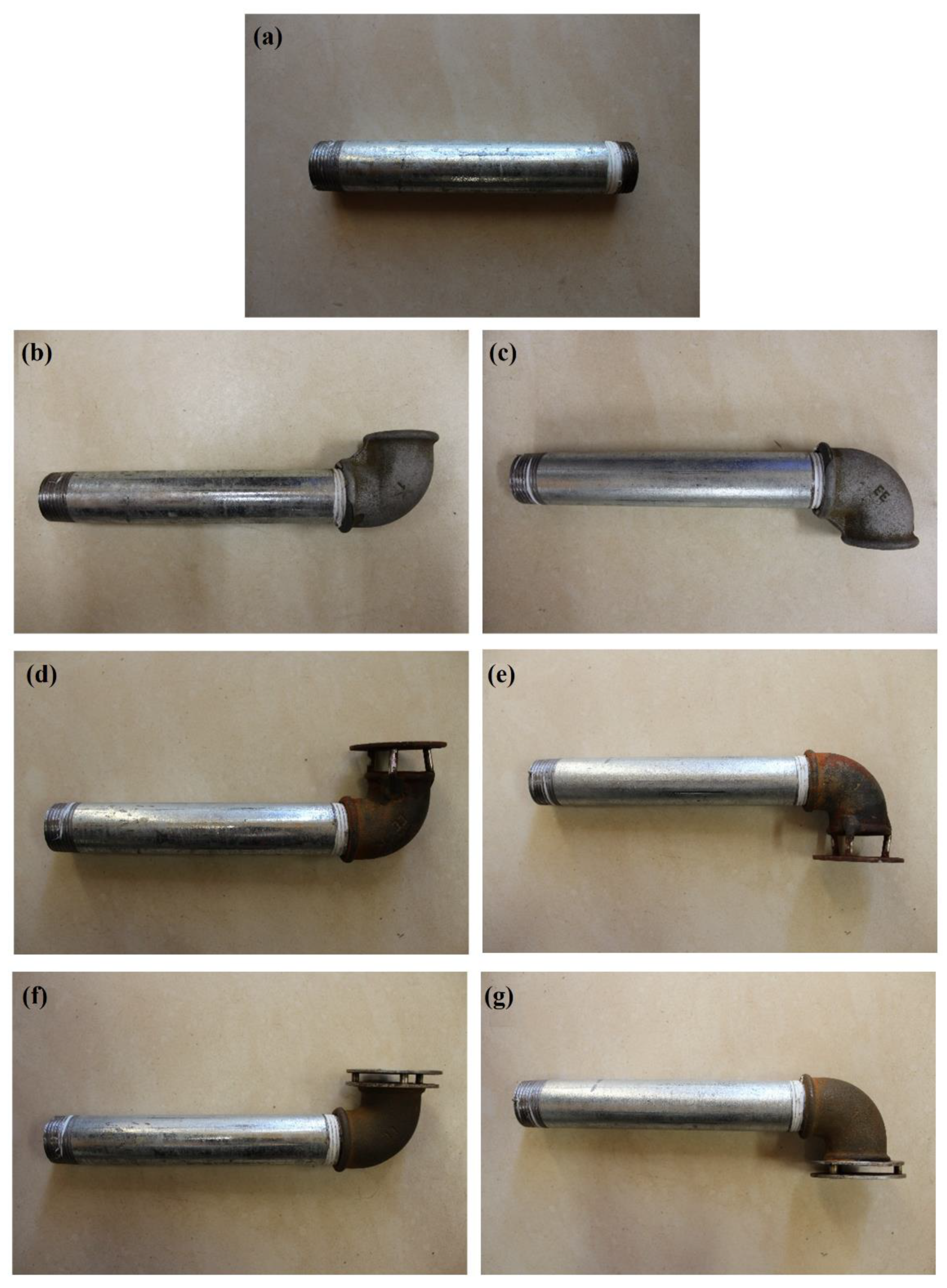
The analysis took into account seven different designs of cold water inlets in order to determine the preferred solution due to the conditions they generate in the DHW tank. The most popular cold water inlet to the tank is the one that introduces cold water horizontally in the lower parts of the tank (W1). There are also solutions of inlets, which are ended with an elbow directed to the upper parts of the tank (W2) or to the lower parts of the tank (W3). On the other hand, the W4–W7 inlet solutions are not commonly found as constructional solutions used in engineering practice. The W4 and W5 inlets, owing to their design, cause a direct loss of energy flowing into the cold water tank. On the other hand, W6 and W7 inlets, owing to the use of the double plate, direct the flow of cold water towards the sidewalls of the tank. Therefore, the following are the detailed results of the research that will illustrate the influence of the cold water inlet on the energy efficiency of the domestic hot water preparation process.
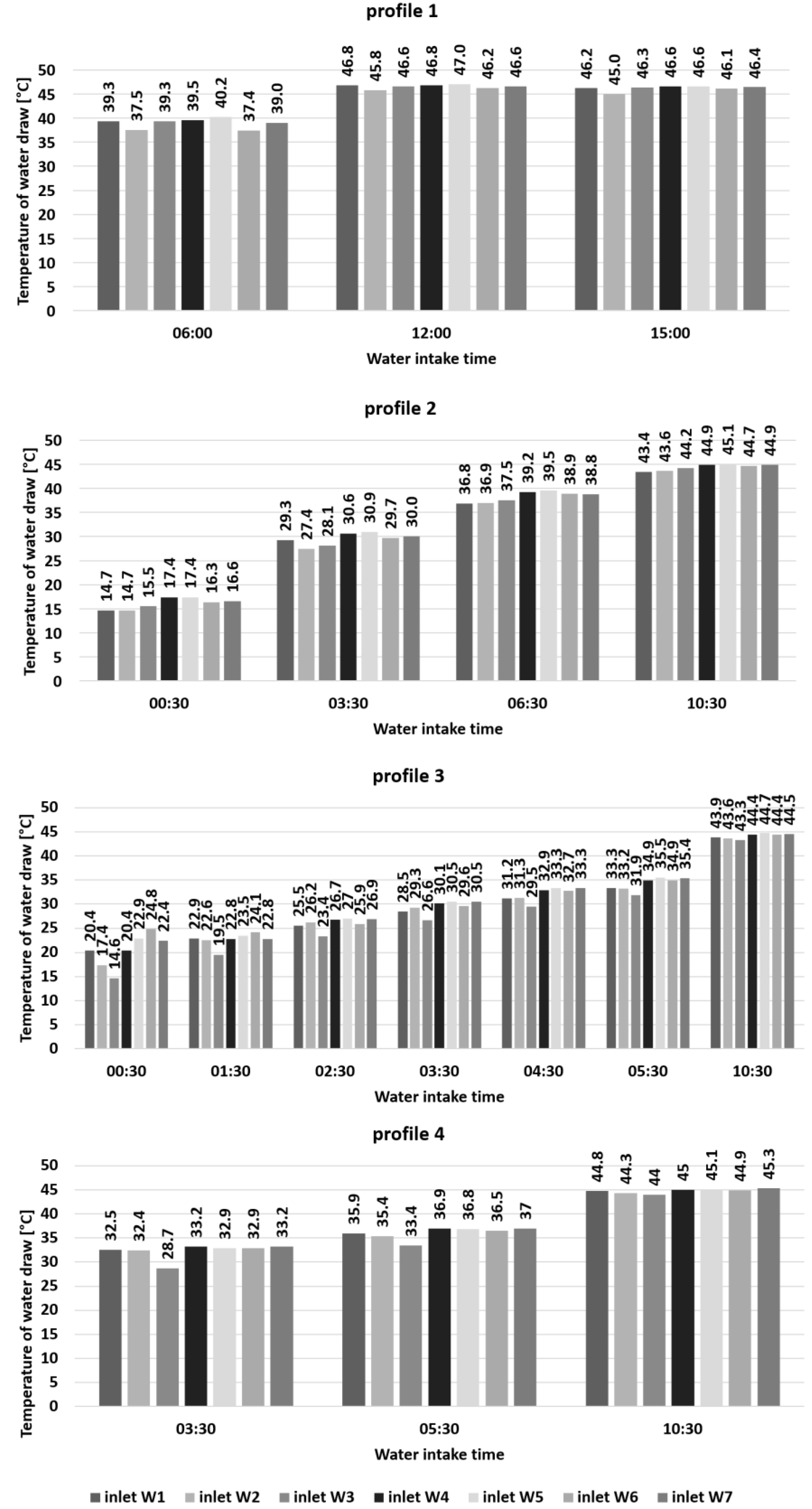
Figure 6 shows the temperatures of water taken from the tank depending on the time of water consumption for particular types of inlets and water consumption profiles. The highest temperature in the case of profile 1 was achieved for inlet W5 (knee to the bottom with a single plate), which is 40.2 °C, 47.0 °C, and 46.6 °C for each water intake time, respectively, and for inlet W4, 39.5 °C, 46.8 °C, and 46.6 °C, respectively. Similar results were obtained for profile 2, where the highest temperatures were also obtained for inlet W4 and W5. For profile 3, for the first two intakes, the highest temperatures were obtained for inlet W6 (elbow directed upwards with a double plate), but in the following hours, the best results were obtained for inlet W5 and W4. The situation is different for profile 4, where the highest intake water temperatures were obtained for inlet W7 (elbow down with a double plate), but these values are similar (difference ±0.3 K) to the inlets W4, W5, and W6.
The lowest temperatures of the intake water were obtained for inlet W2 (elbow up without plate) for profiles 1 and 2. Additionally, for profile 3, small values of this parameter were recorded for inlet W1. In profiles 3 and 4, the worst results were obtained for inlet W3 (elbow down without plate). Low initial temperatures in profiles 2 and 3 (14.7 °C and 14.6 °C, respectively) result from the fact that the first intake took place half an hour after switching on the ultrathermostat, while in other cases, it took place after several hours of its operation. However, this does not affect the comparative results of different types of inlets.
Taking into account the above-mentioned results, it can be seen that the cold water inlets, the design of which allows for the loss of energy of cold water flowing into the tank (inlet W4 and inlet W5) or directing the flow of cold water towards the side walls with the simultaneous reduction of energy of the incoming cold water (inlets W6 and W7), allow obtaining a higher value of hot water temperature in the upper parts of the tank compared to the W1–W3 inlets. Because inlets W1–W3 do not reduce the energy of the cold water flowing into the tank, this strongly influences the temperature of water in the upper parts of the tank. However, such inlets (W1–W3) are commonly used in the engineering practice in tanks, which are produced by different companies, and in this light, they do not provide energy-efficient solutions.
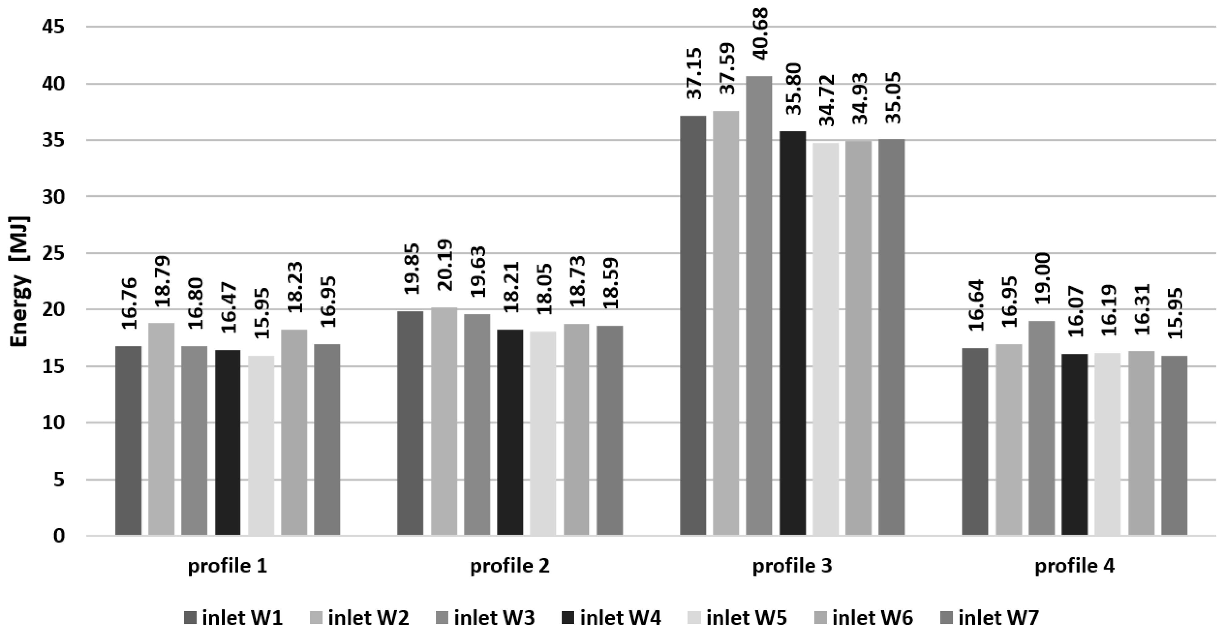
Taking into account the temperature values of hot water in the upper parts of the tank (based on the readings from the T15 sensor, which was located at the level of the hot water outlet from the tank), an analysis was carried out below in the scope of the total amount of energy needed to heat up the taken hot water from the tank to the assumed value of 55 °C (EDHW), which is shown in Figure 7. The best effect was achieved for inlet W5 for profile 1. The amount of energy that had to be provided for this variant was 15.95 MJ, which is 15.2% less than the option with inlet W2 (18.79 MJ), showing the highest energy demand for this profile. In the case of profile 2, the least energy for water heating was supplied in the configuration with inlet W5 (elbow down with a single plate) in the amount of 18.05 MJ, and the most with inlet W2 (20.19 MJ), which is 10.6% more in comparison with the most advantageous option. These results are valid because the calculated mean relative error of δ E D H W was equal to 2.5%.
While analyzing profile 3, it can be concluded that the most energy-efficient option is also the configuration with inlet W5 (elbow facing down with a single plate), in which the energy demand during the experiment was 34.72 MJ. A small difference could also be seen at inlet W6 (elbow facing upwards with a double plate)—34.93 MJ and at inlet W7 (elbow facing downwards with a double plate)—35.05 MJ. The most energy was used in the variant with inlet W3 (elbow facing down without a plate)—40.68 MJ. The difference between the best and worst cases was 14.65%. However, the greatest difference between the two extreme cases was recorded for profile 4, where it was 16.05%. The most energy-efficient variant with inlet W7 (elbow facing down with a double plate) showed a demand of 15.95 MJ, the worst variant with inlet W3 (elbow facing down without a plate)—19 MJ.
Summarizing this part of the analysis, it was noted that the smallest additional energy consumption (EDHW), i.e., the highest energy efficiency, was characterized by the W5 inlet because the total consumption in the whole analysis (profiles 1–4) was 84.91 MJ. The W4 inlet was characterized by a slightly higher total consumption (86.55 MJ). These were followed by W6 and W7 inlets, where the total consumption was 88.2 MJ and 86.54 MJ, respectively. Much higher total energy consumption (at 90.4 MJ) occurred in the W1 inlet. In turn, the worst results were obtained for the W2 and W3 inlets, and they are 93.52 MJ and 96.11 MJ, respectively.
Therefore, on the basis of the above, it can be concluded that it is justified to use inlets in hot water preparation tanks, the design of which allows losing the energy of cold water flowing into the tank (inlet W4 and inlet W5) or directing the flow of cold water towards the side walls with a simultaneous reduction of energy of incoming cold water (inlet W6 and W7), in contrast to cold water inlets, which are commonly used in engineering practice (W1–W3). It was noted that in the case of the W4–W7 inlets, the location of the elbow in the upper or lower parts of the tank does not significantly affect the values of analyzed parameters.
The differences in temperature values in the upper parts of the tank (Figure 6) and in the EDHW range result, among other things, are from the way the cold water stream and its energy (related to the pressure) flowing into the tank are directed. Therefore, the analysis of the stratification number (Str) is presented below. Thermal stratification is the occurrence of an arrangement of water layers in a water body. It is a result of different densities of hot and cold water. Water with a higher temperature has a lower density and therefore moves to the top of the reservoir. A higher stratification number means greater thermal stratification. Better stratification, on the other hand, allows for a higher outlet water temperature and reduces the energy required to heat the water to the required temperature. Therefore, one should aim for the highest possible values for this parameter, but for the cases of hot water tanks without hot water partitions or with hot water partitions but with cold water inlets, it allows losing the energy of cold water flowing into the tank.
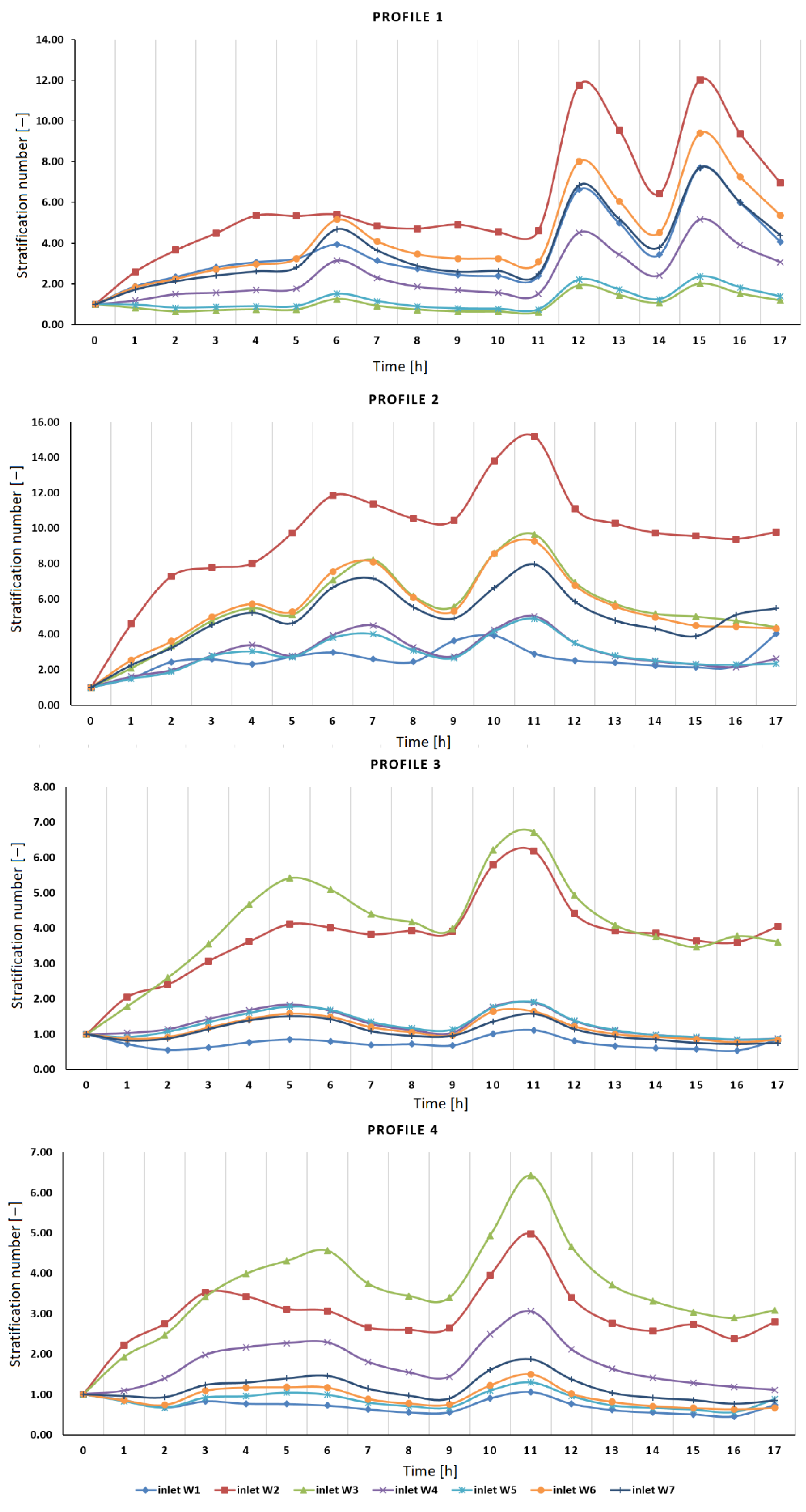
Determination of this parameter allowed evaluating thermal stratification inside the hot water tank with division into four hot water partition profiles for individual cold water inlets to the tank (Figure 8). The calculations were made for seventeen hours of the experiment. The average values of the stratification number for individual inlets with a division into profiles are presented in Table 3.
For profile no. 1, the highest stratification number was obtained for inlet W2 (elbow facing up without a plate) in the fifteenth hour of measurements (Str = 12.03). A slightly lower value (Str = 11.76) was obtained for this inlet in the twelfth hour of the experiment. The lowest values of the stratification number were found for inlet W3 throughout the entire duration of the experiment. The average value of the stratification number (Stravg) for this inlet was 1.03. The inlet W5 was characterized by slightly higher values (Stravg = 1.22).
The number of stratification for profile 2 also reached the highest values for inlet W2. The maximum value of 15.18 was calculated in the eleventh hour of the experiment, while the average for the whole period of the experiment was 9.52. In this case, inlet W3 was ranked in second place to the seventh hour of the experiment. Earlier higher values of the stratification number were calculated for inlet W6. The smallest values were obtained for the inlet W1; the average value of this parameter for the whole test period was 2.59. Low values were also shown inlet W5 (Stravg = 2.85) and inlet W4 (Stravg = 2.95).
When testing thermal stratification in the hot water reservoir in the case of profile 3, the highest values of stratification number were recorded for inlets W3 (Stravg = 4.07) and W2 (Stravg = 3.75). Inlet W1 showed the lowest values of this parameter (Stravg = 0.75). The remaining inlets achieved approximate results among themselves.
In the case of profile 4, inlet W3 was characterized by the highest values of the stratification number (Stravg = 3.57). High values were also obtained for inlet W2 (Stravg = 2.92). The lowest stratification number was shown for inlet W1 (Stravg = 0.72); slightly higher values were obtained for inlet W5 (Stravg = 0.85). Despite the low number of stratification of the W1 and W5 inlets, the obtained results are acceptable as they are higher than the mean relative error of δ S t r , amounting to 0.3%.
The increase in the stratification number is related to the hot water intake from the tank. During the hours of consumption, characteristic peaks are visible. They are particularly visible in the case of inlet W2, where the stratification number was the highest. For the inlets characterized by lower values of this parameter, the differences in individual hours of the experiment are not as clear.
The number of stratification is the most commonly analyzed parameter during hot water storage tank studies. For example, Zachár et al. [33] also analyzed the effect of using plates located opposite the inlets. They showed that the use of plates gives better stratification in storage tanks and that the plate diameter has no significant effect on the thermocline occurring in the tank when cold water flows in from the bottom of the tank. A similar result was obtained by Shah and Furbo [36], who compared three different inlet designs: a plain pipe, a pipe with a small semi-circular baffle placed on top, and an inlet with a flat baffle placed 0.01 m above a 0.3 m diameter pipe. The tank with the plate inlet obtained the highest degree of stratification, while the tank with the pipe inlet obtained the lowest degree of stratification. According to Li et al. [34], the thermal stratification was also lowest for the slit-type inlet facing the bottom of the tank, as opposed to the direct or spray-type inlet. The slotted-type inlet was more likely to limit the mixing progress and motivate thermal stratification. Moreover, a slotted-type inlet could deliver hot water for a longer period of time at the same discharge rate. The plate, despite the presence of holes, significantly increased the efficiency of the system and reduced electricity consumption. The use of plates opposite the cold water inlet (inlets W4–W7) resulted in reduced turbulent movement and mixing of water during the charging of the storage tank due to the lower velocities and their relatively smooth distribution along the horizontal direction between the edge of the plate and the wall.
However, it should be mentioned that most of the previous tests were made with storage tanks supplied directly (without a heating coil) or a mantle tank and without additional hot water drawn and cold water inlet. That is why the influence of these additional processes in the present study, based on the above-mentioned analysis regarding the energy needed to heat up the taken hot water from the tank (EDHW), showed that the Str of such a tank (with a spiral coil) should be as low as possible in order to improve the energy efficiency of DHW production.
The thermal performance of a heat storage system depends on the degree of stratification. A well-stratified tank is always able to provide higher exergy and a better utilization rate with less heat input compared to an isothermal mixed tank with the same energy content [
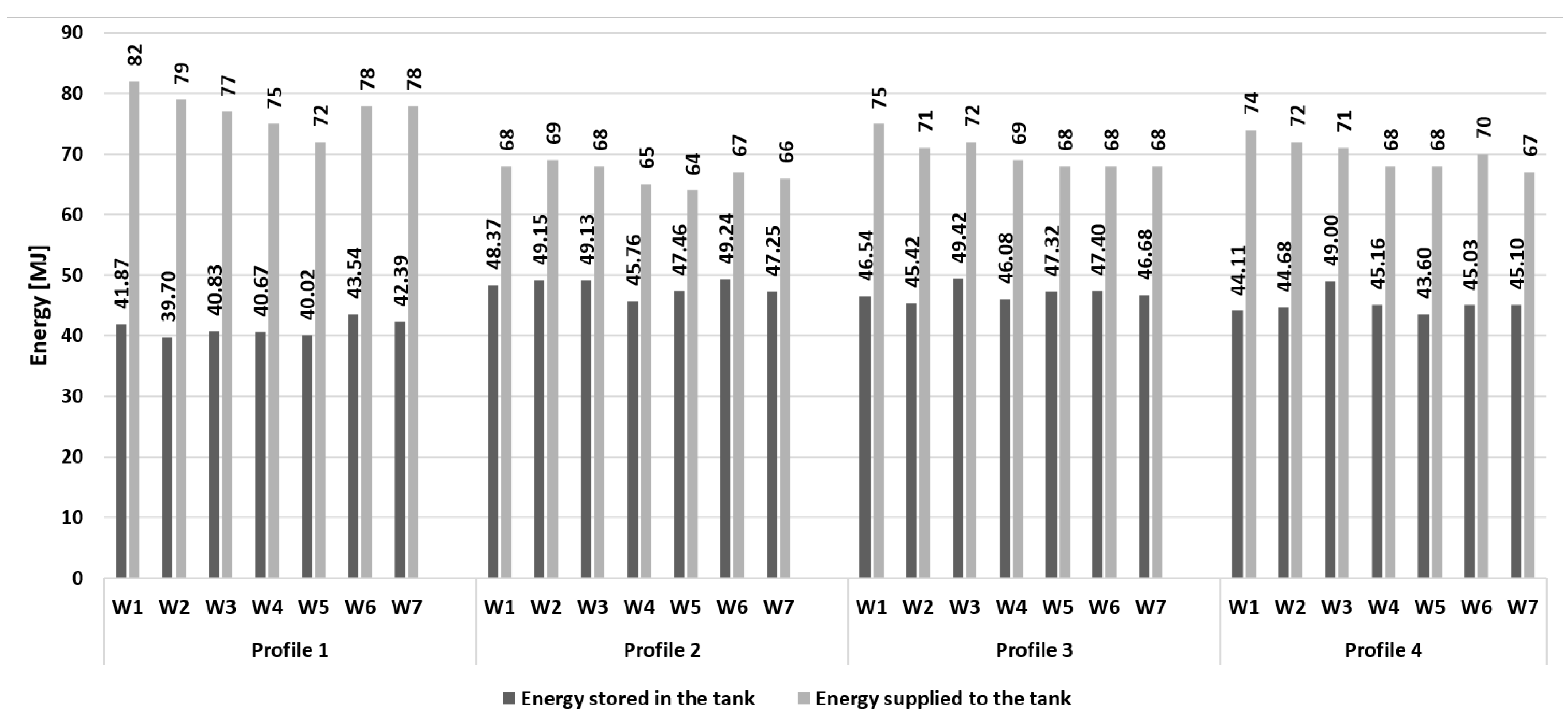
14]. Therefore, in the last stage of the experiment, the energy stored in the reservoir and the energy efficiency of the system were calculated. The obtained results are presented in Figure 9 and Table 4.
When considering profile 1, it was noted that for the configuration with the inlet with two plates facing upwards (inlet W6), the most energy was stored, i.e., 43.54 MJ. In this case, too, the highest value of heat accumulation efficiency of 56% was achieved. Almost identical efficiency was achieved for a system comprising an elbow with one plate facing down (inlet W5). The remaining inlets were characterized by efficiency in the range of 50–54%.
Profile 2 showed both the highest amount of stored energy in the tank and the highest value of heat accumulation efficiency, over 70%. The value of accumulated energy over 49 MJ was recorded for three inlets—W2, W3, and W6. The highest energy efficiency was calculated for inlet W5, amounting to 74%. The lowest efficiency was shown for inlet W7 (70%).
In the case of profile 3, the highest amount of energy stored in the hot water tank (49.42 MJ) was read for a system with inlet W3—elbow type facing down without a plate. It achieved an efficiency of 69%, while the highest efficiency of 70% was obtained by inlets W5 and W6. The inlet W1 was least efficient, reaching a value of 62%.
While analyzing profile 4, it was noticed that the efficiency of heat accumulation was the highest for inlet W3 (69%). For this variant, the highest level of energy stored in the tank, amounting to 49 MJ, was also noted. The remaining inlets reached the value of this parameter from 43.6 MJ to 45.16 MJ. A considerable discrepancy between the most effective system and other modifications is visible here. The system efficiency values (over 50%) for all profiles with a relatively low average relative error ( δ E j = 2.6% and δ η t a n k = 3.1%) prove the high efficiency of the proposed solutions.
Similar findings were obtained by Hegazy [41], who investigated three different inlet geometries (wedged, perforated, and slotted) and showed that the inlet design plays a key role in determining the thermal performance of a hot water tank. Mixing at an inlet equipped with an obstruction regulates the build-up of thermal stratification inside the heater tank and therefore reduces the degree of mixing. This results in better thermal performance because more hot water is discharged at a nearly constant temperature.

3.2. Impact Analysis of Obstacles Placed in the Tank

In addition to the cold water inlets (see 
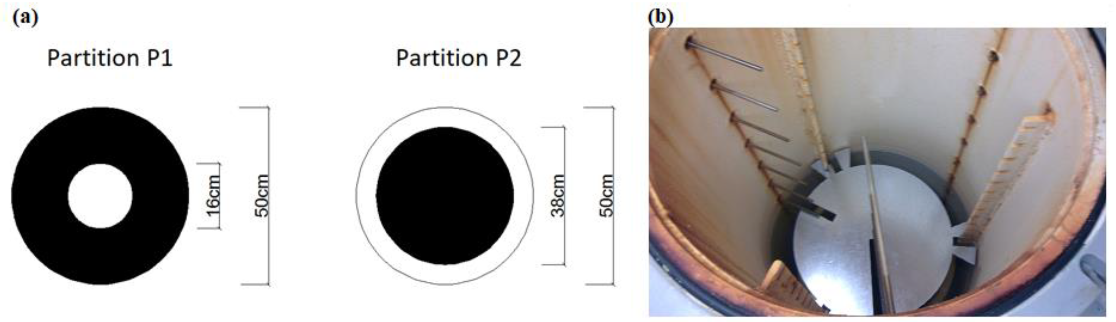
Section 3.1), the efficiency of the hot water preparation process can also be affected by obstacles placed inside the tank. Therefore, this analysis was performed to observe two extreme cases of obstacles; that is, P1, which only allows water to flow inside the tank through the middle of the tank, and P2, which only allows water to flow inside the tank at the tank walls. Each obstacle was also studied at three different heights in the tank. In this case, seven analyzed variants were obtained.
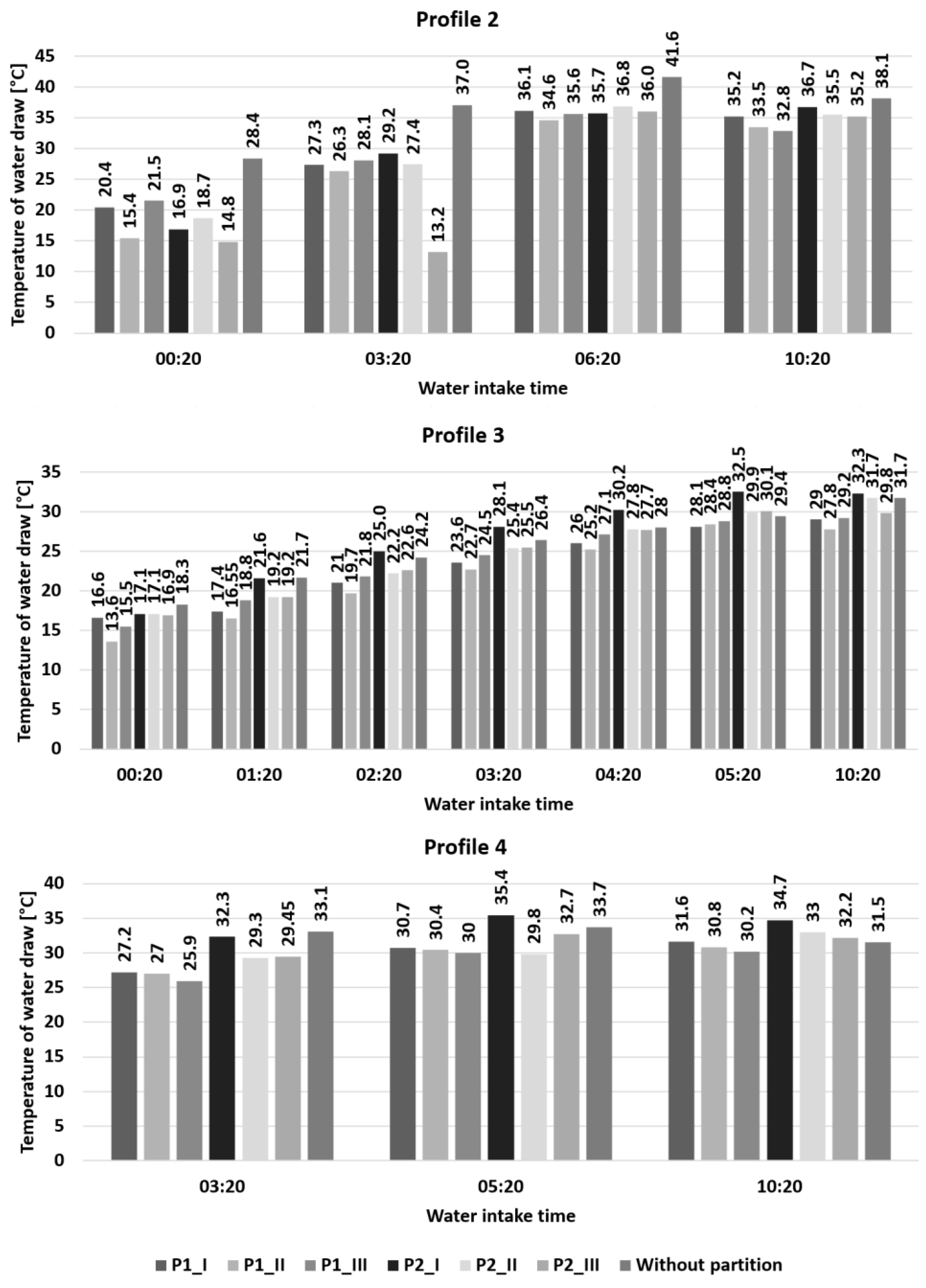
The analysis of the influence of the obstacles inside the tank began with a comparison of the temperature of the water intake (TDHW_tank), depending on the hour of water consumption for particular types of obstacles and partition profiles. The hot water intake from the tank was carried out for profiles 2–4 (profile 1—no hot water intake), and for these variants, the results are shown in Figure 10. For profile 2, the highest temperature values were obtained when there was no partition in the tank. They were 28.4 °C, 37.0 °C, 41.6 °C, and 38.1 °C, respectively, for individual water consumption. The results are very different for using obstacles. High temperatures were obtained using an obstacle P1 located in the upper part of the tank and obstacle P2 installed in the middle and bottom of the tank. The lowest temperatures were obtained with the configuration of obstacle P2 located on the top of the tank during the first two dissections (temperatures were 14.8 °C and 13.2 °C, respectively) and obstacle P1 located in the middle of the tank during two consecutive dissections. While analyzing the results obtained for profile 3, one can see that the results are less varied. The highest temperatures of the water intake were obtained with the configuration of obstacle P2, located in the upper part of the tank. Only in the first two offtakes, slightly higher temperature values were recorded in the variant without a partition.
The lowest values were recorded for the set with obstacle P1 located at the central height of the tank. Slightly higher results were obtained for the remaining locations of obstacle P1. Much better results were obtained when obstacle P2 was used. Moreover, higher values of the temperature of water taken up were achieved in the absence of the obstacle.
Similar relationships between the variants were obtained in the case of the analysis of profile 4. Here, the highest outlet water temperatures were also recorded for obstacle P2 at the bottom of the tank and the lowest for obstacle P1 at the top of the tank. With the increase of the obstacle mounting height, a decrease in the temperature of the intake water was observed for obstacle P1. For obstacle P2, such dependencies were only visible during the third intake.
Summarizing this part of the analysis, it can be stated that more favorable results (higher value of TDHW_tank) were obtained for obstacle P2 in comparison with obstacle P1, i.e., for the variant when water flow is forced into the upper parts of the tank at the tank walls and not through the middle of the tank. Additionally, more favorable results were obtained when the obstacle (P1 or P2) was placed on level I than on level III, which is connected with and could result from the process of temperature stabilization in the upper parts of the tank and thermal stratification process in the tank. Different results were obtained by Altuntop et al. [22] because they achieved higher temperatures for a horizontal obstacle with a hole in the middle of the obstruction.
This is connected with the fact that in the present study, the tank with a spiral coil (no direct supply) was investigated, and the cold water inlet into the tank was under high pressure (3 bar) in the middle parts of the tank. This caused obstacle P1 (with a hole in the middle) to not properly limit the influence of cold water coming into the tank during draw-offs of hot water.
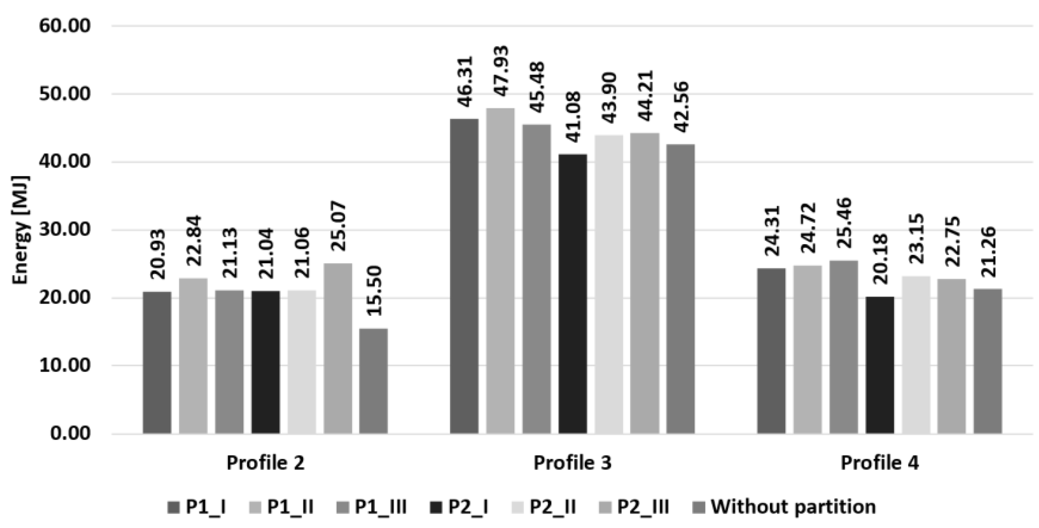
The above was also confirmed during the analysis of the total amount of energy needed to heat the water taken up to the value of 55 °C for each profile (Figure 11). In the case of profile 2 analysis, the lowest energy demand was shown when no obstacle in the tank (15.5 MJ) was used. The lowest value was also obtained for obstacle P1, located at the bottom of the tank (20.93 MJ). The highest energy demand was recorded with obstacle P2 in the upper part of the tank (25.07 MJ). While analyzing profile 3, it was noticed that the most effective solution was the use of obstacle P2 at the bottom of the tank. In this case, 41.08 MJ of energy was supplied, which was 14.3% less than in the least favorable variant, i.e., obstacle P1 placed in the middle (47.93 MJ). This is a high level of energy saving, taking into account the small average relative error of δ E D H W = 2.5%. Similarly, in profile 4, the variant with obstacle P2 at the bottom of the tank (20.18 MJ) proved to be the least energy-consuming solution. The most energy for water heating was used in the configuration with obstacle P1 in the upper parts of the tank (25.46 MJ).
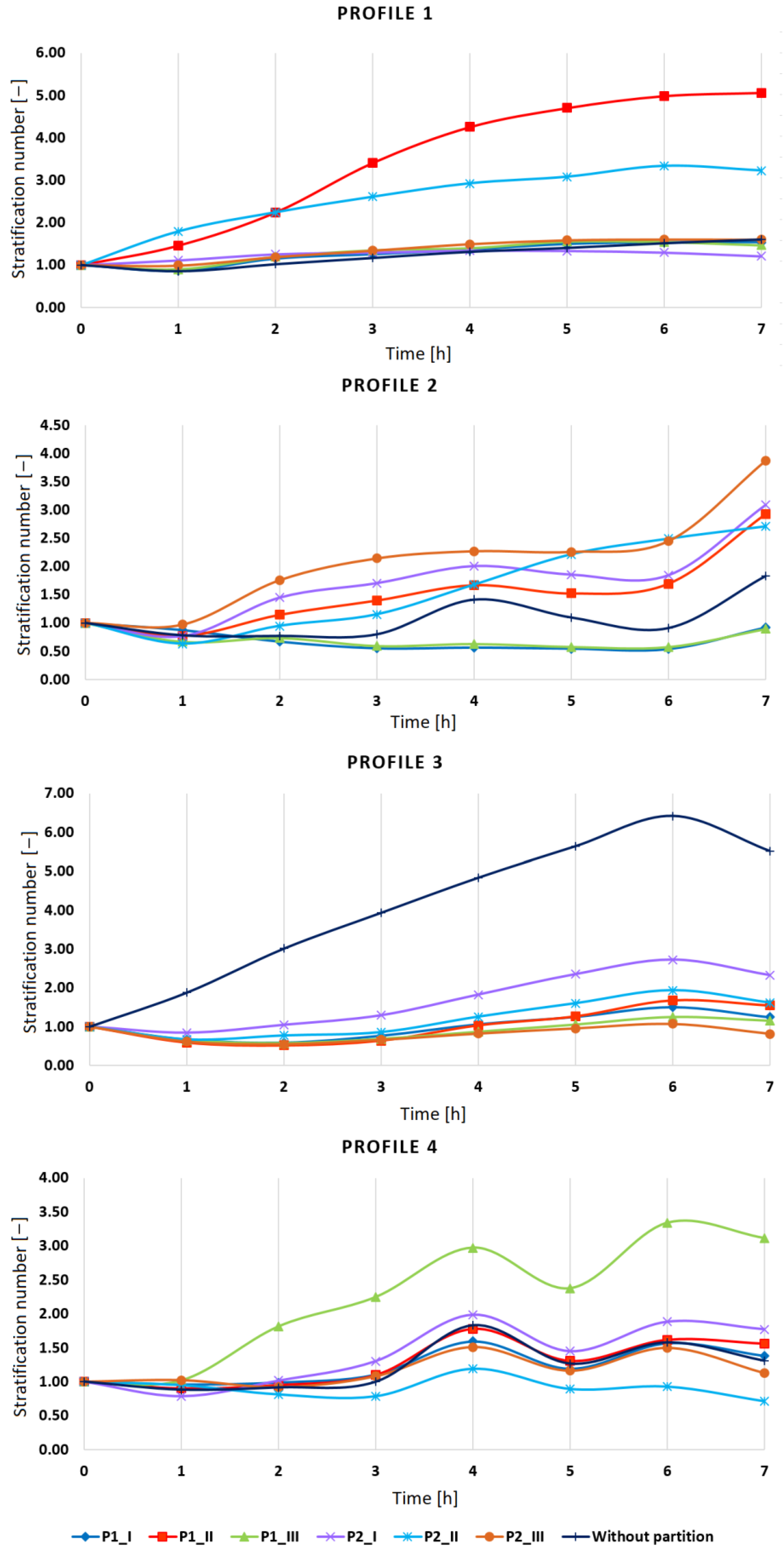
In order to demonstrate the reason for the above results, an analysis of the number of thermal stratification in the hot water storage tank was carried out with division into four hot water consumption profiles for individual partition configurations, as shown in Figure 12. The calculations were performed for the first seven hours of the experiment. The average values of the stratification number for individual inlets with division into profiles are presented in Table 5.
In the case of profile 1, the highest stratification number was obtained for the variant of obstacle P1 located in the middle part of the tank, Stravg = 3.39. A slightly lower value was obtained for obstacle P2, also in the middle of the tank height (Stravg = 2.52). Other configurations showed very similar average values of numerous stratifications. The lowest values were obtained for obstacle P2 at the bottom of the tank and when no partition was used. In both cases, Stravg = 1.23.
By testing the thermal stratification in the DHW tank in the case of profile 2, the highest values of stratification number were obtained for the variant with obstacle P2 located in the upper part of the buffer tank. The average for the whole test period was 2.09. The smallest values were obtained for obstacle P1 located in the lower and upper part; the average value of this parameter for these configurations was 0.71. The remaining variants reached Stravg from the range 1.07–1.71. The stratification number for profile 3 reached the highest values for the variant without the obstacle (Stravg = 4.03). The lowest values of this parameter were shown by the variant with partition located in the center of the tank, both obstacle P1 and obstacle P2 (Stravg = 0.90 and Stravg = 0.81, respectively). Other configurations reached values above 1.0–1.67. In the case of profile 4, the highest values of the stratification number are characterized by the system with obstacle P1 at the top of the tank (Stravg = 2.23). The lowest stratification number was shown by obstacle P2 in the middle part (Stravg = 0.91). Despite the low mean values of the stratification number (0.71 or 0.90), the obtained results are acceptable, as they are higher than the mean relative error of δ S t r equal to 0.3%.
Similar results were obtained by Altuntop et al. [22] as well as Erdemir and Altuntop [23], who showed that the obstacle types with a gap in the middle have better thermal stratification than those with water flowing against the tank walls. In the absence of an obstacle, the hot and cold water at the tank entrance are in contact with each other over the entire axial cross-section. The rotations of the velocity vectors of the warm and cold water occur because they hit the tank wall. Under this condition, the warm water stratification is destroyed by the cold water. In order to maintain greater thermal stratification, the axial contact area of the cold and hot water should be reduced, and the cold water should not be directed toward the top of the tank.
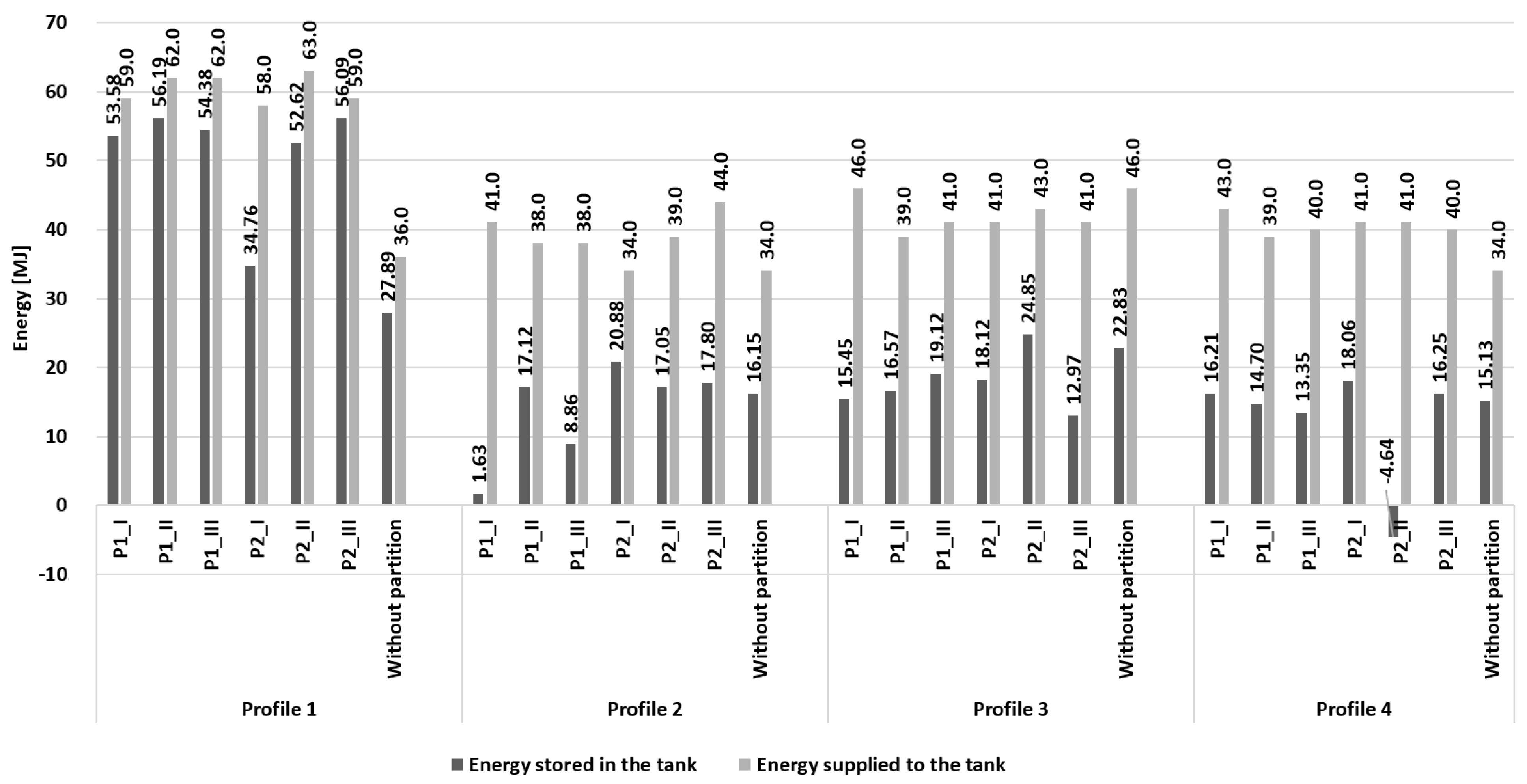
On the basis of this analysis and discussion of results, it can be seen that the use of obstacles close to the lower parts of the tank (level I) allows minimizing the phenomenon of thermal stratification in the upper parts of the tank and thus obtaining higher energy efficiency of the hot water preparation process. The obtained results of the calculated energy stored in the tank and the energy efficiency of the system are presented in Figure 13 and Table 6.
The most advantageous option for profile 1 was the use of obstacle P2 in the upper part of the tank, where the energy efficiency of the system was 95%. In this case, the most energy was stored—56.09 MJ. The most energy was stored during the application of obstacle P1 in the middle of the tank (56.19 MJ). However, the large amount of energy supplied reduced the efficiency of the system to 91%, which is still one of the higher efficiencies. The least effective, in this case, was the variant without an obstacle, achieving 78% efficiency.
When considering profile 2, it was noted that for the configuration with obstacle P2 located in the lower part of the tank, the highest efficiency of the system was achieved, as much as 61%, storing 20.88 MJ of energy when supplying the tank 34 MJ. Definitely, the lowest amount of stored energy (only 1.63 MJ), and thus energy efficiency (4%) was achieved by the system with obstacle P1 at the bottom of the tank. Moreover, placing this obstacle in the upper part of the tank significantly reduced the storage capacity of the tank. The storage capacity was 8.86 MJ of energy with a supply of 38 MJ, achieving a system efficiency of 23%.
For profile 3, efficiency was achieved at a similar level as for profile 2. Here, too, the highest efficiency (58%) was achieved by a configuration with partition P2, but placed at a higher level (center of the tank). Additionally, the most energy was accumulated in this option—24.85 MJ. It is 11.87 MJ more than in the least favorable variant, i.e., also for obstacle P2, but located in the upper part of the tank. The efficiency of the system was 32%. Slightly higher efficiency was achieved by obstacle P1—tank bottom configuration (34%).
The analysis of the results from profile 4 showed that the most effective variants are obstacle P2 in the lower part of the tank and the lack of partition, achieving an energy efficiency of 44%. The option with an obstacle made it possible to store more energy in the tank by 2.93 MJ but required 7 MJ more energy. Obstacle P2—the center of the tank—did not store energy in the tank and even reached a negative value. This may indicate a system failure, and it is worth repeating the measurements, especially as this is a single situation. Among other configurations, the system with obstacle P1 located in the upper part of the tank showed the lowest efficiency. It accumulated 13.35 MJ of energy with a supply of 40 MJ, which gives an efficiency of 33%.
In spite of the differences in the analyzed studies by different authors, it is possible to make a general statement that the use of obstacles inside the hot water tank promotes an increase in thermal stratification. This is due to the fact that placing an obstacle inside the tank in a horizontal jacketed hot water tank improved the thermal performance of the tank because the obstacle acted as a thermal and flow barrier. As also observed by Erdemir et al. [21], the obstacle blocked the flow of cold water from the main inlet. Obstacles also increase the energy storage capacity to the position of the obstruction. That is why using an obstacle inside the tank is an easy and inexpensive way to provide better thermal stratification. Thus, better thermal stratification provides improved energy storage capacity, higher temperature at the consumption outlet, and lower temperature at the outlet.

4. Conclusions

Experimental research was carried out in order to examine different designs of cold water inlets to the DHW tank, the use of different partitions inside the tank, and select optimal options influencing the energy efficiency of the hot water preparation process. The tests were carried out for a system, the main element of which was a hot water tank equipped with fifteen 5 cm-long temperature sensors installed in the tank at 10 cm intervals. The heating medium supply to the system was provided by an ultrathermostat, which also made it possible to read the energy supplied and stored in the system. In the first stage of the research, seven cold water inlets of different designs were analyzed, affecting the water supply to the tank in different ways. In the second stage, two types of obstacles placed on three levels in the tank (bottom, top, center) were analyzed.
The obtained results of temperature measurements of water at the outlet and in the tank made it possible to examine the energy efficiency, number of stratification, and energy efficiency of the system for each of the variants. In addition, tests were carried out for different profiles of hot water partitioning in order to examine the dependence of temperature changes in the water intake on the amount and frequency of intake. On the basis of the measurements and calculations, it was noticed that the configuration of the cold water inlet to the capacity tank and the application inside the obstacles significantly affects the accumulation and energy efficiency of the domestic hot water tank.
Inlet W5 (elbow down with a single plate) proved to be the most advantageous variant of all tested, as the system in which it was used showed the best energy efficiency and the lowest energy demand for hot water heating in the buffer tank (EDHW = 84.91 MJ). The worst results were obtained for inlets W2 (elbow up without a plate, EDHW = 93.52 MJ) and W3 (elbow down without a plate, EDHW = 96.11 MJ), depending on the profile of the dissection. However, in the case of maintaining the highest possible level of stratification in the hot water tank, the use of inlets W2 and W3 was the most beneficial. The use of a plate reduces the speed of water entering the tank so that there is no sudden mixing of cold and hot water. Additionally, directing the cold water inlet to the bottom directs its stream to the zone of the heating coil, where it is heated. The idea of maintaining good thermal stratification is to maintain a stable vertical temperature gradient throughout the tank cycle. The proper configuration, location, and shape of the cold water inlet are intended to minimize mixing of cold and hot water and maximize stratification.
The analysis of the use of obstacles inside the tank has shown that the use of obstacle P2, where the water flow takes place on the sides of the tank, is the most advantageous in most cases. The particularly advantageous option in terms of energy efficiency, the amount of accumulated energy in the tank, and the smallest energy requirement for heating hot water is to place this obstacle in the lower (EDHW = 82.30 MJ) or central part of the tank (EDHW = 88.11 MJ). Using obstacle P1 (water flow to the upper parts of the tank through the middle) resulted in much worse results. Similarly, the lack of the partition yields worse results in comparison to the application of obstacle P2. In this variant, cold water is stopped in the lower part of the buffer tank, where it is heated by a coil located there, and there is no violent mixing in the upper part of the tank with hot water.
These results applied in engineering practice (in the construction of DHW tanks) may increase the energy efficiency of the DHW production process by very low additional investment costs.
Future research on this topic may be related to the method of easy and wide applications of presented measures or other solutions in the existing DHW tanks in order to increase energy efficiency. Subsequent studies may also consider pressure loss in the tank (from the water inlet to the outlet) in order to analyze the issue from an economic point of view.

Author Contributions

Study conception and design: A.M., T.C. and A.S.-O.; Acquisition, analysis, and interpretation of data: A.M., T.C. and A.S.-O.; Drafting of the manuscript: A.M.; Critical revision: T.C. and A.S.-O. All authors have read and agreed to the published version of the manuscript.

Funding

This research received no external funding.

Institutional Review Board Statement

Not applicable.

Informed Consent Statement

Not applicable.

Data Availability Statement

The data presented in this study are available on request from the corresponding author.

Conflicts of Interest

The authors declare no conflict of interest.

References

  1. De Rosa, M.; Bianco, V.; Scarpa, F.; Tagliofico, L. Heating and Cooling Building Energy Demand Evaluation; A Simplified Model and Modified Degree Days Approach. Appl. Energy 2014, 128, 217–229. [Google Scholar] [CrossRef]
  2. D’Alonzo, V.; Novelli, A.; Vaccaro, R.; Vettorato, D.; Albatici, R.; Diamantini, C.; Zambelli, R. A Bottom-Up Spatially Explicit Methodology to Estimate the Space Heating Demand of the Building Stock at Regional Scale. Energy Build. 2020, 206, 109581. [Google Scholar] [CrossRef]
  3. Bekun, F.V.; Alola, A.A.; Sarkodie, S.A. Toward a Sustainable Environment: Nexus between CO2 Emissions, Resource Rent, Renewable and Nonrenewable Energy in 16-EU Countries. Sci. Total. Environ. 2019, 657, 1023–1029. [Google Scholar] [CrossRef] [PubMed]
  4. Rayner, T. Keeping It in the Ground? Assessing Global Governance for Fossil-Fuel Supply Reduction. Earth Syst. Gov. 2021, 8, 100061. [Google Scholar] [CrossRef]
  5. Kober, T.; Schiffer, H.W.; Densing, M.; Panos, E. Global Energy Perspectives to 2060—WEC’s World Energy Scenarios 2019. Energy Strategy Rev. 2020, 31, 100523. [Google Scholar] [CrossRef]
  6. Perez-Lombard, L.; Ortiz, J.; Pout, C. A Review on Buildings Energy Consumption Information. Energy Build. 2008, 40, 394–398. [Google Scholar] [CrossRef]
  7. Pomianowski, M.Z.; Johra, H.; Marszal-Pomianowska, A.; Zhang, C. Sustainable and Energy-Efficient Domestic Hot Water Systems: A Review. Renew. Sustain. Energy Rev. 2020, 128, 109900. [Google Scholar] [CrossRef]
  8. Cholewa, T.; Siuta-Olcha, A.; Anasiewicz, R. On the Possibilities to Increase Energy Efficiency of Domestic Hot Water Preparation Systems in Existing Buildings—Long Term Field Research. J. Clean. Prod. 2019, 217, 194–203. [Google Scholar] [CrossRef]
  9. Siuta-Olcha, A. Application of a Probabilistic Method for Determination of the Thermal Field in a Flat-Plate Solar Collector. Arch. Environ. Prot. 2007, 33, 67–81. [Google Scholar]
  10. Siuta-Olcha, A. Thermal Processes in Solar Domestic Hot-Water System. Environ. Prot. Eng. 2006, 32, 95–101. [Google Scholar]
  11. Wang, Z.; Zhang, H.; Dou, B.; Huang, H.; Wu, W.; Wang, Z. Experimental and Numerical Research of Thermal Stratification with a Novel Inlet in a Dynamic Hot Water Storage Tank. Renew. Energy 2017, 111, 353–371. [Google Scholar] [CrossRef]
  12. Wang, Z.; Zhang, H.; Huang, H.; Dou, B.; Huang, X.; Goula, M.A. The Experimental Investigation of the Thermal Stratification in a Solar Hot Water Tank. Renew. Energy 2019, 134, 862–874. [Google Scholar] [CrossRef]
  13. Kurşun, B. Thermal Stratification Enhancement in Cylindrical and Rectangular Hot Water Tanks with Truncated Cone and Pyramid Shaped Insulation Geometry. Sol. Energy 2018, 169, 512–525. [Google Scholar] [CrossRef]
  14. Chandra, Y.P.; Matuska, T. Stratification Analysis of Domestic Hot Water Storage Tanks: A Comprehensive Review. Energy Build. 2019, 187, 110–131. [Google Scholar] [CrossRef]
  15. Knudsen, M.D.; Petersen, S. Model Predictive Control for Demand Response of Domestic Hot Water Preparation in Ultra-Low Temperature District Heating Systems. Energy Build. 2017, 146, 55–64. [Google Scholar] [CrossRef]
  16. Jin, X.; Maguire, J.; Christensen, D. Model Predictive Control of Heat Pump Water Heaters for Energy Efficiency. In Proceedings of the 18th ACEEE Summer Study on Energy Efficiency in Buildings, Pacific Grove, CA, USA, 21–26 August 2014; pp. 133–145. [Google Scholar]
  17. Kazmi, H.; D’Oca, S.; Delmastro, C.; Lodeweyckx, S.; Corgnati, S.P. Generalizable Occupant-Driven Optimization Model for Domestic Hot Water Production in NZEB. Appl. Energy 2016, 175, 1–15. [Google Scholar] [CrossRef]
  18. Gómez, M.A.; Collazo, J.; Porteiro, J.; Míguez, J.L. Numerical Study of an External Device for the Improvement of the Thermal Stratification in Hot Water Storage Tank. Appl. Therm. Eng. 2018, 144, 996–1009. [Google Scholar] [CrossRef]
  19. Bouhal, T.; Fertahi, S.; Agrouaz, Y.; El Rhafiki, T.; Kousksou, T.; Jamil, A. Numerical Modeling and Optimization of Thermal Stratification in Solar Hot Water Storage Tanks for Domestic Applications: CFD Study. Sol. Energy 2017, 157, 441–455. [Google Scholar] [CrossRef]
  20. Ievers, S.; Lin, W. Numerical Simulation of Three-Dimensional Flow Dynamics in a Hot Water Storage Tank. Appl. Energy 2009, 86, 2604–2614. [Google Scholar] [CrossRef] [Green Version]
  21. Erdemir, D.; Atesoglu, H.; Altuntop, N. Experimental Investigation on Enhancement of Thermal Performance with Obstacle Placing in the Horizontal Hot Water Tank Used in Solar Domestic Hot Water System. Renew. Energy 2019, 138, 187–197. [Google Scholar] [CrossRef]
  22. Altuntop, N.; Arslan, M.; Ozceyhan, V.; Kanoglu, M. Effect of Obstacles on Thermal Stratification in Hot Water Storage Tanks. Appl. Therm. Eng. 2005, 25, 2285–2298. [Google Scholar] [CrossRef]
  23. Erdemir, D.; Altuntop, N. Improved Thermal Stratification with Obstacles Placed Inside the Vertical Mantled Hot Water Tank. Appl. Therm. Eng. 2016, 100, 20–29. [Google Scholar] [CrossRef]
  24. Dragsted, J.; Furbo, S.; Dannemand, M.; Bava, F. Thermal Stratification Built Up in Hot Water Tank with Different Inlet Stratifiers. Sol. Energy. 2017, 147, 414–425. [Google Scholar] [CrossRef] [Green Version]
  25. Esen, M.; Durmuş, A. Geometric Design of Solar-Aided Latent Heat Store Depending on Various Parameters and Phase Change Materials. Sol. Energy. 1998, 62, 19–28. [Google Scholar] [CrossRef]
  26. Yang, Z.; Chen, H.; Wang, L.; Sheng, Y.; Wang, Y. Comparative Study of the Influences of Different Water Tank Shapes on Thermal Energy Storage Capacity and Thermal Stratification. Renew. Energy. 2016, 85, 31–44. [Google Scholar] [CrossRef]
  27. Żukowski, M. Experimental Determination of the Cold Water Temperature at the Inlet to Solar Water Storage Tanks. Therm. Sci. Eng. Prog. 2020, 16, 100466. [Google Scholar] [CrossRef] [Green Version]
  28. Rendall, J.D.; Gluesenkamp, K.R.; Worek, W.; Abu-Heiba, A.; Nawaz, K.; Gehl, T. Empirical Characterization of Vertical-Tube Inlets in Hot-Water Storage Tanks. Int. Commun. Heat Mass Transf. 2020, 119, 104838. [Google Scholar] [CrossRef]
  29. Assari, M.R.; Tabrizi, H.B.; Savadkohy, M. Numerical and Experimental Study of Inlet-Outlet Locations Effect in Horizontal Storage Tank of Solar Water Heater. Sustain. Energy Technol. Assess. 2018, 25, 181–190. [Google Scholar] [CrossRef]
  30. Kaloudis, E.; Grigoriadis, D.G.E.; Papanicolaou, E.; Panidis, T. Large Eddy Simulation of Thermocline Flow Phenomena and Mixing during Discharging of an Initially Homogeneous or Stratified Storage Tank. Eur. J. Mech.–B/Fluids. 2014, 48, 94–114. [Google Scholar] [CrossRef]
  31. Dehghan, A.A.; Barzegar, A. Thermal Performance Behavior of a Domestic Hot Water Solar Storage Tank during Consumption Operation. Energy Convers. Manag. 2011, 52, 468–476. [Google Scholar] [CrossRef]
  32. Lavan, Z.; Thompson, Y. Experimental Study of Thermally Stratified Hot Water Storage Tanks. Sol. Energy. 1977, 19, 519–524. [Google Scholar] [CrossRef]
  33. Zachar, A.; Farkas, I.; Szlivka, F. Numerical Analyses of the Impact of Plates for Thermal Stratification Inside a Storage Tank with Upper and Lower Inlet Flows. Sol. Energy. 2003, 74, 287–302. [Google Scholar] [CrossRef]
  34. Li, S.; Zhang, Y.; Li, Y.; Zhang, X. Experimental Study of Inlet Structure on the Discharging Performance of a Solar Water Storage Tank. Energy Build. 2014, 70, 490–496. [Google Scholar] [CrossRef]
  35. Abdelhak, O.; Mhiri, H.; Bournot, P. CFD Analysis of Thermal Stratification in Domestic Hot Water Storage Tank during Dynamic Mode. Build. Simul. 2015, 8, 421–429. [Google Scholar] [CrossRef]
  36. Shah, L.J.; Furbo, S. Entrance Effects in Solar Storage Tanks. Sol. Energy. 2003, 75, 337–348. [Google Scholar] [CrossRef]
  37. Chandra, Y.P.; Matuska, T. Numerical Prediction of the Stratification Performance in Domestic Hot Water Storage Tanks. Renew. Energy. 2020, 154, 1165–1179. [Google Scholar] [CrossRef]
  38. Oliveski, R.; Krenzinger, A.; Vielmo, H.A. Comparison between Models for the Simulation of Hot Water Storage Tanks. Sol. Energy. 2003, 75, 121–143. [Google Scholar] [CrossRef]
  39. Furbo, S. Heat Storage for Solar Heating Systems. In Educational Note BYG DTU U-071; Department of Civil Engineering Technical University of Denmark: Kongens Lyngby, Denmark, 2005; Available online: https://orbit.dtu.dk/en/publications/heat-storage-for-solar-heating-systems (accessed on 29 September 2021).
  40. Mawire, A.; Taole, S.H. A Comparison of Experimental Thermal Stratification Parameters for an Oil/Pebble-Bed Thermal Energy Storage (TES) System during Charging. Appl. Energy. 2011, 88, 4766–4778. [Google Scholar] [CrossRef]
  41. Hegazy, A.A. Effect of Inlet Design on the Performance of Storage-Type Domestic Electrical Water Heaters. Appl. Energy. 2007, 84, 1338–1355. [Google Scholar] [CrossRef]
Figure 1. Diagram of an N-section tank with a spiral coil in its lower part [39].
Energies 14 06509 g001
Figure 2. Diagram of the existing research installation for domestic hot water preparation: 1—hot water tank; 2—ultrathermostat; 3—heat meter; 4—drain solenoid valve; 5—flow meter; 6—diaphragm expansion vessel; 7—variable displacement pump; 8—regulation and measurement system; 9—regulator; 10—partition inside the tank; 11—cold water connection; 12—hot water connection; 13—counter-current heat exchanger.
Energies 14 06509 g002
Figure 3. Hot water storage tank: (a) test setup; (b) schema.
Energies 14 06509 g003
Figure 4. Inlet variants used in the test: (a) inlet W1; (b) inlet W2 (elbow directed upwards); (c) inlet W3 (elbow directed downward); (d) inlet W4 (elbow directed upwards with a single plate); (e) inlet W5 (elbow directed downward with a single plate); (f) inlet W6 (elbow directed upwards with a double plate); (g) inlet W7 (elbow directed downward with a double plate).
Energies 14 06509 g004
Figure 5. Schema of the horizontal partitions located in the hot water tank (a) and view of partitions during installation in the tank (b).
Energies 14 06509 g005
Figure 6. Temperature of water drawn from the tank (TDHW_tank).
Energies 14 06509 g006
Figure 7. The amount of energy needed to heat the water intake to 55 °C (EDHW).
Energies 14 06509 g007
Figure 8. Stratification number inside the tank during hot water consumption.
Energies 14 06509 g008
Figure 9. Amount of energy stored and supplied to the tank.
Energies 14 06509 g009
Figure 10. Temperature of the intake water from the tank (TDHW_tank).
Energies 14 06509 g010
Figure 11. Amount of energy needed to heat up the water to 55 °C.
Energies 14 06509 g011
Figure 12. Stratification number inside the tank during hot water consumption.
Energies 14 06509 g012
Figure 13. The amount of energy stored and delivered to the tank.
Energies 14 06509 g013
Table 1. Schedule of hot water consumption for inlets.
Water Intake TimeAmount of Hot Water Drawn
Profile 106:00150 dm3
12:00100 dm3
15:00100 dm3
Profile 200:30
03:30
06:30
10:30
50 dm3
50 dm3
50 dm3
50 dm3
Profile 300:30
01:30
02:30
03:30
04:30
05:30
10:30
50 dm3
50 dm3
50 dm3
50 dm3
50 dm3
50 dm3
50 dm3
Profile 403:30100 dm3
05:3050 dm3
10:3080 dm3
Table 2. Schedule of hot water consumption for partitions.
Water Intake TimeAmount of Hot Water Drawn
Profile 1-without consumption
Profile 200:20
03:20
06:20
10:20
50 dm3
50 dm3
50 dm3
50 dm3
Profile 300:20
01:20
02:20
03:20
04:20
05:20
10:20
50 dm3
50 dm3
50 dm3
50 dm3
50 dm3
50 dm3
50 dm3
Profile 403:20100 dm3
05:2050 dm3
10:2080 dm3
Table 3. Average stratification number (Str).
Inlet W1Inlet W2Inlet W3Inlet W4Inlet W5Inlet W6Inlet W7
Profile 13.575.981.032.411.224.273.64
Profile 22.599.525.502.952.855.474.96
Profile 30.753.754.071.271.271.141.06
Profile 40.722.923.571.740.850.941.14
Table 4. Energy efficiency of the system.
Inlet W1Inlet W2Inlet W3Inlet W4Inlet W5Inlet W6Inlet W7
Profile 151%50%53%54%56%56%54%
Profile 271%71%72%70%74%73%72%
Profile 362%64%69%67%70%70%69%
Profile 460%62%69%66%64%64%67%
Table 5. Average stratification number (Str).
P1_IP1_IIP1_IIIP2_IP2_IIP2_IIIWithout Partition
Profile 11.273.391.301.232.521.351.23
Profile 20.711.520.711.711.602.091.07
Profile 31.011.030.901.671.210.814.03
Profile 41.221.282.231.400.911.161.22
Table 6. Energy efficiency of the system.
P1_IP1_IIP1_IIIP2_IP2_IIP2_IIIWithout Partition
Profile 191%91%88%92%88%95%77%
Profile 24%45%23%61%44%40%48%
Profile 334%42%47%44%58%32%50%
Profile 438%38%33%44%−11%41%44%
Publisher’s Note: MDPI stays neutral with regard to jurisdictional claims in published maps and institutional affiliations.

