Abstract
Reliability is a fundamental requirement in electric propulsion systems, involving a particular approach in studies on system failure probabilities. An intrinsic improvement to the propulsion system involves introducing robust architectures such as fault-tolerant motor drives to these systems. Considering the potential for hardware failures, a fault-tolerant design approach will achieve reliability objectives without recourse to optimized redundancy or over-sizing the system. Provisions for planned degraded modes of operation are designed to operate the motor in fault-tolerant mode, which makes them different from the pure design redundancy approach. This article presents how a five-phase permanent-magnet synchronous motor operates under one- or two-phase faults, and how the system reconfigures post-fault motor currents to meet the torque and speed requirement of reliable operation that meets the requirements of an electric propulsion system.
1. Introduction
In automotive, marine, and railway applications, electric machines and their drive systems have recently gained significant commercial interest due to their potential for higher energy efficiencies, higher peak power, faster power response, and lower emissions as compared to conventional solutions [1,2]. Characteristics such as high power and torque density, increased starting torque, great hill-climbing ability, reliability, robustness appropriate to the environment, low acoustic noise, low torque ripple, good voltage regulation over a wide speed range, and acceptable cost [1,3,4,5,6,7,8] are the main reasons for the growing trend towards automotive electrification.
Similarly, conventional engines are being replaced by electric motors and drive systems with the advancements in the fields of electric machines and power electronics [9,10,11]. Electric propulsion systems allow maneuver flexibility; easy maintenance; reliability; reduced logistics; and architectural flexibility in ship design, environment protection, and reductions in acoustic signatures [8]. Various different topologies of electric machines have been used for electric propulsion [12,13,14,15]. In order to simplify the maintenance of electromechanical drives and increase the global reliability of the ship propulsion system, DC machines were the first to be used in this field [16]. Gradually, DC machines have been replaced by induction and permanent-magnet motors [12,17,18,19].
Critical applications, such as in the ship propulsion, automotive, and aeronautics industries, demand a high reliability, and it is essential for them to be able to operate under fault conditions. Especially in the case of ship propulsion, where any failure of the system would compromise the safety of the crew, it is crucial to continue the operation of the propulsion system even when a fault occurs. This is why the electric propulsion system is required to be highly fault-tolerant [20,21,22,23]. Research has concluded that multiphase machines and drive systems have various advantages over conventional electric power systems, which offer improved fault tolerance [24], and various kinds of fault-tolerant methods for multiphase machines have been reported [25,26,27,28]. In high-power applications, the selection of such multiphase machines offers reduced constraints in drive components by power splitting among different inverter legs. Due to these potential advantages, multiphase machines are a prime choice for ship propulsion applications [29,30].
This paper concentrates on the design of a five-phase permanent magnet synchronous motor (PMSM) and an adequate fault-tolerant control to continue motor operation smoothly in the case of open-phase faults. Differently from the direct quadrate (DQ) model, we present a lumped-element model for the five-phase motor which gives an insight into each phase behavior in case of the occurrence of a fault [31]. Most significantly, the optimum arrangement of current vectors is found to obtain the maximum achievable average torque by reducing ripples in the torque to a considerable value. The current vectors are symmetrically arranged [32], unlike where asymmetrical arrangements have been used to maximize torque. The symmetrical arrangement of current vectors abolishes the need to access a machine’s neutral point. Therefore, there is no change in the power-converter topology and no additional connection between the neutral point and the split capacitor, which are conventional solutions [33,34]. This is an important advantage presented in this paper.
The proposed technique was simulated on PLECS by Plexim, and its feasibility was verified by Finite Element Analysis (FEA) using Elmer, and a JMAG 3.5 kW 1500 rpm five-phase permanent-magnet synchronous motor was used as a propulsion motor. The TMS320F28377D DSP board was used as a control board.
2. Fault-Tolerant Drive Modeling
2.1. Five-Phase Permanent Magnet Motor
A five-phase permanent-magnet synchronous motor (PMSM) was used as a propulsion motor. Five-phase star-connected winding topology was used in the propulsion motor, as shown in Figure 1. It can be modeled in the natural reference frame by the following Equation (1) [35,36]:
where Rs = 14e−3 stator resistance and L is inductance, vas–ves are phase voltages, ias–ies are phase currents, and eas–ees are Back Electromotive Force (emf) due to the permanent magnets of the motor, which can be stated as in (2).
where ωr, λm, θr, and epm are the electrical rotor speed, the peak strength of the flux linkage due to the permanent magnets, the electrical rotor position, and the back emf due to the permanent magnets.
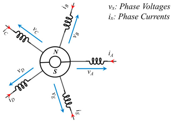
Figure 1.
The winding topology of a five-phase permanent-magnet synchronous motor.
The electromagnetic torque developed by the motor can be driven by co-energy relationships, and, for surface-mounted PMSM, is given by (3):
where Te(SM), p, and Tcog are the electromagnetic torque of the PMSM, pole pair, and cogging torque of the machine. The mechanical equation of the machine is given by (4):
where J, B, and Qp are the moment of inertia, viscous damping, and mechanical load due to the propeller.
2.2. Design and FEM Analysis of a Five-Phase Permanent-Magnet Motor
This section deals with the design and analysis of a five-phase PMSM. The benchmark motor rating was set to 3.5 kW and the operating speed was 1500 RPM. The terminal voltage rating requirement was 48 VDC. The machine was a totally enclosed non-ventilated (TENV) motor. The current density was 6.0 A/mm2. The phase and line voltages of the PMSM were set to 16 Vrms and 18.8 Vrms. A cross-section of the five-phase PMSM is illustrated in Figure 2a, and the winding configuration—a double-layer distributed lap winding—is shown in Figure 2b. The design parameters of the five-phase PMSM are given in Table 1, along with the material properties in Table 2.
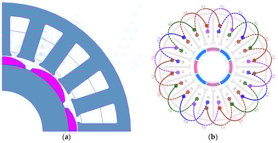
Figure 2.
Design representation of the five-phase PMSM: (a) cross-section, (b) winding configuration.

Table 1.
Design parameters of the five-phase PMSM.
Table 2.
Material list for the five-phase PMSM.
A 2D FEM analysis was performed to realize the five-phase PMSM; the simulation was performed on Elmer FEA as well as on JMAG. The FEA summary is presented in Table 3 and compared with the JMAG results. It should be noted that, until now, the current component taking over the iron losses has not been included in the study, the line-to-line voltages are presented in rms, and the mechanical losses are also not considered in this study.
Table 3.
FEM result summary.
In the FEM analysis, the final design of the PMSM, as modeled, is presented in Figure 3. It also illustrates the mesh distribution, flux density, Joule loss density, and iron loss density. The models from both ELMER and JMAG are compared.
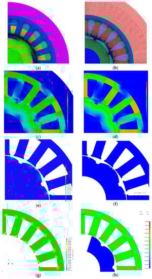
Figure 3.
(a) Mesh distribution, Elmer; (b) mesh distribution, JMAG; (c) flux density, Elmer; (d) flux density, JMAG; (e) Joule loss density, Elmer; (f) Joule loss density, JMAG; (g) iron loss density, Elmer; (h) iron loss density, JMAG.
2.3. Load Torque at Variable Speeds
The machine torque (Te) must be opposed by an equal and opposite load torque (Qp) for the machine to operate at a steady rotational speed. If Te is greater than Qp, the machine will accelerate, and it will decelerate if Qp is greater than Te. The mathematical relation for this can be seen in (4).
By assuming a load torque with the optimum speed variation, the relationship between the load torque and speed can be drawn as (5) [37]:
2.4. Power Converter
The propulsion motor was fed with a five-leg PWM VSI inverter. The inverter performed the task of speed control of the propulsion motor; the topology of the inverter used is illustrated in Figure 4. This is obtained from the switching states of each leg as in (6), where Si = 1 if the upper switch is on and Si = 0 for the opposite case.
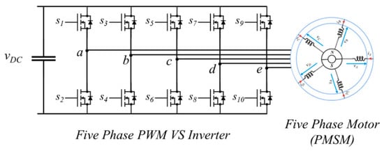
Figure 4.
Five-phase Voltage Source Inverter (VSI) topology.
3. Fault-Tolerant Control
This section deals with the rearrangement of post-fault motor currents to obtain the maximum achievable power. The proposed approach revolves around the idea that having an optimized arrangement of post-fault currents is necessary to achieve the optimum selection point between the maximum achievable average torque and the minimum amount of torque ripples.
3.1. Reconfiguration of Post-Fault Currents
A well-known vector diagram for a healthy five-phase system is illustrated in Figure 5a. Starting with the one-phase fault, consider that phase A is open, ensuring open-phase fault—i.e., ia = 0. This creates a gap between the adjacent phases B and E, leaving behind the asymmetrical arrangement of the current vectors, as illustrated in Figure 5b.
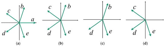
Figure 5.
Vector space diagrams: (a) healthy operation; (b) phase A open; (c) phase A and C open; (d) phase A and B open.
Similarly, the situation gets worse in the case of two-phase fault. Firstly, consider two non-adjacent phase faults. Assuming that phase A and C are permanently open, the result is an open-phase fault; the current vectors are shown in Figure 5c. For an adjacent phase fault, phase A and B are permanently open and the gap between C and E is considerable, as shown in Figure 5d.
As a working hypothesis, the proposed solution for the stated condition is to align the remaining phases symmetrically. Some reasonable constraints are fixed accordingly [22,23], such as:
- Currents must be sinusoidal.
- Each healthy phase must maintain the same current amplitude.
- Post fault currents must be symmetrical to avoid zero sequence currents; the constraint Σi* = 0 must be satisfied.
In order to achieve the required goal, the current vectors are forced to align themselves symmetrically. In the case of a one-phase fault, a new set of four current vectors is introduced. Vector B is set at 45° and each current vector is 90° apart from each other, as shown in Figure 6a. This arrangement is acceptable because it fulfills the condition of having zero amplitude of homopolar current due to an isolated neutral point. The equation of the reference currents can be given as (7)–(10), where θm is the angular position of the rotor and φ is the offset angle, to are the post-fault motor currents, and IM is the amplitude of the post-fault motor currents.
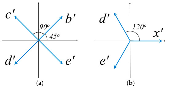
Figure 6.
Configuration of the proposed vector space diagrams: (a) one-phase fault; (b) two-phase fault.
Similarly, addressing the two open-phase faults, the post-fault motor currents must be reconfigured symmetrically so that the sum of the currents will be zero. In doing so, the new current vectors are introduced. These vectors are 120° apart from each other, similar to the conventional three-phase system shown in Figure 6b. The reference currents in the case of a two-phase fault can be calculated as (11)–(13); “x” can be either phase B or C depending on whether the type of open-phase fault is adjacent or non-adjacent.
3.2. Average Torque and Ripples Evaluation
For an electric motor, the relation for torque can be derived in terms of back emf* and phase currents i* as in (14), where ω is the speed of the motor.
It is clear from (14) that the angle between the back emf and current is of significant importance. Losing one or more motor phases results in an imbalance. In order to avoid zero-sequence current and to balance the post-fault motor currents, a study was performed to find the optimum offset angle (φ) for the current Equations (7)–(13) we derived in the previous section.
3.2.1. Torque Estimation of a One-Phase Fault
Figure 7a illustrates the torque variation with respect to the offset angle (φ) in the case of a one-phase fault. The offset angle of −10° gives the maximum achievable average torque, but at 9° we achieve the minimum number of ripples in the torque with comparatively less compromise in the average torque; therefore, 9° was chosen as the optimum offset angle for this paper. The vector illustration of the post-fault motor current and the proposed solution are presented in Figure 7b.
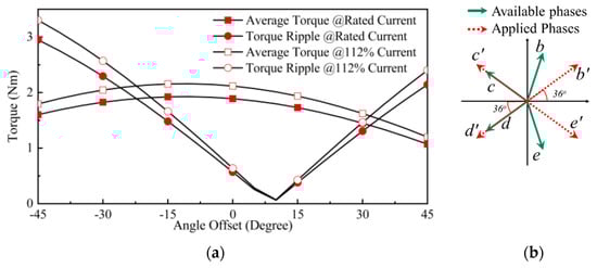
Figure 7.
(a) Torque with respect to the offset angle for a one-phase fault; (b) proposed solution for a one-phase fault.
3.2.2. Torque Estimation of a Two-Phase Fault
Similarly, Figure 8a and Figure 9a illustrate the torque variation with respect to the offset angle (φ) for two non-adjacent and adjacent phase fault cases. The maximum average torque is achieved at −75° for non-adjacent two-phase faults and −95° for adjacent two-phase faults, whereas the ripples in the torque are almost the same from −180° to 30°. It should be noted that the average torque in two adjacent phase faults is less than that of one non-adjacent-phase fault because, in order to make the post-fault current balanced, a comparatively larger phase displacement is performed as compared to two non-adjacent phase fault cases. A graphical illustration of the post-fault motor current and the proposed solution is shown in Figure 8a and Figure 9a.
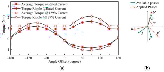
Figure 8.
(a) Torque with respect to the offset angle for two non-adjacent phase faults; (b) proposed solution for two non-adjacent phase faults.
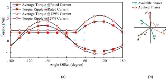
Figure 9.
(a) Torque with respect to the offset angle for two adjacent phase faults; (b) proposed solution for two adjacent phase faults.
4. Simulation Results
4.1. PLECS Model Results
The simulation of the presented system was performed on PLECS by Plexim, the block diagram in Figure 10. The simulation model, model parameters, and specifications of a five-phase PMSM are given in Table 4. A 48 VDC source wa used to supply the five-phase inverter. The five-phase PMSM was first accelerated to 1500 rpm using the feedback current control and the machine operation at a healthy condition was analyzed and compared with the available DQ models [38,39].
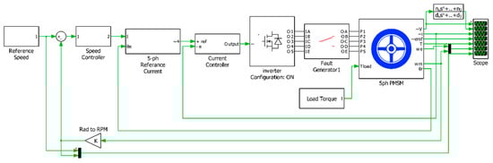
Figure 10.
A simulation model for the fault-tolerant control of the five-phase PMSM.
Table 4.
Modeling parameters of the five-phase PMSM.
The machine was then subjected to a one-phase open-circuited fault by breaking the connection at the fault-generating block at a time of 0.10 s. The immediate effect can be seen as increased motor currents in Figure 11. The increase in the post-fault motor current is limited by the relation as in (15) in order to avoid any additional losses.
where “iN”, “iO”, and “e” are the post-fault current, the pre-fault current, and the number of available phases.
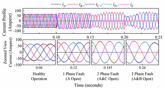
Figure 11.
The current profile of a 5-phase PMSM.
At a time of 0.15 s, the system was subjected to two non-adjacent phase faults (phase A and C), and at a time of 0.20 s phase C was turned back on whilst B was off, resulting in two adjacent phase faults (phase A and B). The motor current profiles are illustrated in Figure 11; it is quite noticeable that the post-fault motor currents are perfectly balanced and have identical amplitudes. The motor current increased by 12% in the case of a one-phase fault and 19% in the case of a two-phase fault. This increase in current value is acceptable because it did not increase the copper losses. As in (15). The fault-tolerant algorithm justification can be seen in Figure 12; the phase shift of the motor currents can be seen in accordance with the motor’s back-emf waveform. The offset angle was chosen in order to make the current in-phase with the back emf as much as possible and to avoid zero-sequence current.
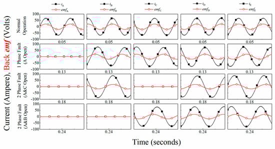
Figure 12.
Current and back-emf profiles in the case of healthy operation and one- and two-phase fault operations.
The torque and speed outputs of the machine are illustrated in Figure 13. The output torque is reduced by 19% in the case of a one-phase fault, 46% in the case of two adjacent phase faults, and 32% for non-adjacent phase faults. This drastic amount of reduction in torque is due to current limitation it can be slightly increased by raising the current limit. The relation between torque and speed is presented earlier in (5), and the output speed is illustrated in Figure 13, showing a little turbulence in two phase fault operation. Figure 14 illustrates the phase voltages of the five phase PMSM during healthy and faulty operation. It can be seen that no reasonable increase in voltage amplitudes. The numerical values of the simulated results can be seen in Table 5.
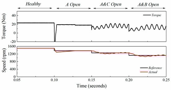
Figure 13.
Torque and speed profiles in case of healthy and one- and two-phase fault operation.
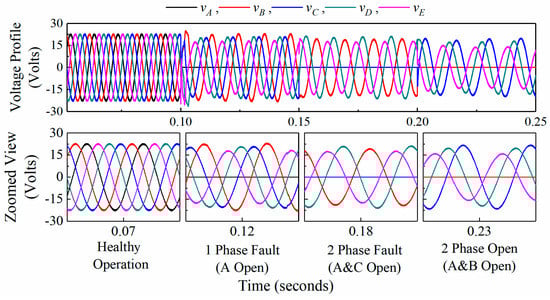
Figure 14.
Phase voltage profile in case of healthy operation, one-and two-phase fault operations.
Table 5.
Numerical output modeling results.
4.2. FEM Modeling Results
In order to validate the proposed approach, a FEM analysis was performed on the design presented in Section 2.2. A five-phase current identical to the healthy, one- and two-phase fault operation modes similar to the current in Figure 11 was applied to the five-phase PMSM in FEM software, and the resultant torque and phase voltages were calculated as illustrated in Figure 15. The results obtained from the FEM analysis show similarities to the results obtained in Section 4.1. Figure 15a shows the voltage, current, and torque profile for the case of a healthy operation. Figure 15b illustrates the voltage, current, and torque profile for a one-phase fault case (A open). Figure 15c,d illustrate the voltage, current, and torque profile for two-phase fault cases (A and C, and A and B open). A numerical comparison is performed in Table 5.
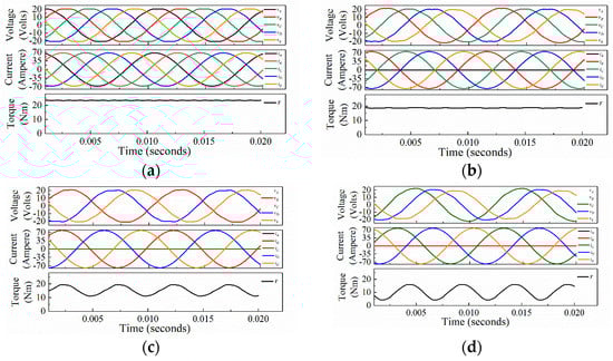
Figure 15.
FEM modeling results: (a) healthy operation; (b) a one-phase fault (A open), (c) a non-adjacent two-phase fault (A and C open), (d) two adjacent phase fault (A and B open).
5. Results
Based on the modeling in the previous section, a five-phase PMSM prototype was fabricated as illustrated in Figure 16. The experiment test bench is illustrated in Figure 17; the test bench was comprised of a personal computer, a DSP control board, a five-phase VSI inverter, a DC power source, and a five-phase PMSM. No-load experiments were performed on a low-speed operation and the results are illustrated in Figure 18 for no-load motor currents for the justification of the proposed fault-tolerant approach. The current profile can be seen as balanced, as was proposed in the previous section for the faulty operations. Figure 19 illustrates the respective speed of the motor for healthy and degraded modes.
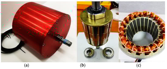
Figure 16.
Prototype: (a) a five-phase PMSM; (b) a permanent magnet rotor; (c) the stator of a five-phase PMSM.
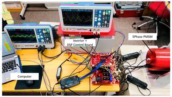
Figure 17.
Experiment test bench.
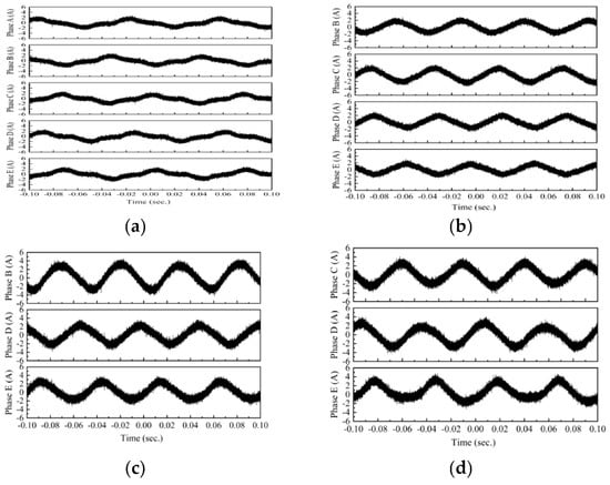
Figure 18.
Current profiles: (a) a healthy operation; (b) a one-phase fault (A open); (c) a non-adjacent two-phase fault (A and C open); (d) an adjacent two-phase fault (A and B open).
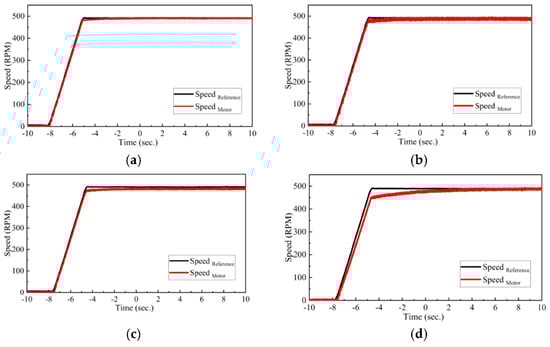
Figure 19.
Rotational speed profiles: (a) a healthy operation; (b) a one-phase fault (A-Open), (c) a non-adjacent two-phase fault (A and C open), (d) an adjacent two-phase fault (A and B open).
Figure 18a illustrates the current profiles for a healthy phase. The phase currents are balanced and identical to each other; Figure 18b shows a phase difference of 90° with currents balanced as proposed earlier in this article for a one-phase fault mode, whereas in Figure 18c,d it is clear that the current profiles have a phase difference of 120° and the motor currents are balanced and identical, which is the whole point of the technique presented in this article.
By applying the currents discussed in Figure 18, we achieve the motor speeds illustrated in Figure 19a, which provides a visualization of healthy phases and illustrates that the motor follows the reference speed, whereas, in Figure 19b, which shows one-phase faults, there is a small delay to track the maximum 500 rpm speed. An explanation for this is that the control algorithm is recalculating the phase since it is a degraded mode. Figure 19c,d show a two-phase fault, and this approach has set a condition in Section 4.1 to limit the losses; therefore, the motor takes longer to track the max reference speed. The goal of this approach is to operate the motor under degraded modes and avoid additional copper losses without using any neutral point. From the results, it is clear that this approach provides the solution for fault-tolerant five-phase PMSM drives and propulsion systems.
6. Conclusions
This paper has presented effective post-fault current control strategies to operate a five-phase permanent magnet synchronous motor indefinitely. A case study was performed to select an optimum point between the achievable maximum average torque and minimum ripples in accordance with the application.
The results presented earlier show an appropriate current control strategy that enables the motor to operate in the occurrence of an open-phase fault and generates a comparatively smooth and adequate amount of average torque in the case of a one-phase fault. The motor torque reduces to 80% with an offset angle of 10°, whereas an offset angle of −10° gives 85% of the average torque with a significant number of ripples. The occurrence of two adjacent open-phase faults proves to be the worst-case scenario and the limitation of the zero-sequence current causes a 54% decrease in the average torque, decreasing by 68% in the case of a non-adjacent two-phase fault.
Ultimately, the aim of this paper was to conclude the results in an analytical form and present the rules to apply to find out the post-fault reference current for multiphase machines. The proposed approach proved to be accurate for controlling multiphase machines.
Both the simulation and the experimental results prove the effectiveness of the proposed fault-tolerant solution presented. Indeed, it has been shown to reproduce the propulsion system dynamics in the laboratory and also the experimental validation of the proposed fault-tolerant control. This proposed solution should be a useful tool for all-electric propulsion systems.
Author Contributions
Conceptualization, J.-W.K. and B.-G.P.; methodology, J.-W.K.; software, M.H.I.; validation, M.H.I. and J.-W.K.; formal analysis, M.H.I.; investigation, M.H.I.; resources, J.-W.K.; writing—original draft preparation, J.-W.K.; writing—review and editing, M.H.I.; visualization, M.H.I.; supervision, J.-W.K.; project administration, J.-W.K.; funding acquisition, J.-W.K. and B.-G.P. All authors have read and agreed to the published version of the manuscript.
Funding
This research was funded by the Ministry of Science, ICT and Future Planning (MSIP), grant number No. 18-12-N0101-27.
Institutional Review Board Statement
Not applicable.
Informed Consent Statement
Not applicable.
Data Availability Statement
Some or all data, models, or code generated or used during the study are available in a repository or online.
Acknowledgments
This work was supported by the Technology Innovation Program (20011693, Development of integrated rear wheel drive module technology for SUV xEV to improve driving energy consumption efficiency by 3%) funded By the Ministry of Trade, Industry & Energy (MOTIE, Korea).
Conflicts of Interest
The authors declare no conflict of interest.
References
- Ehsani, M.; Yimin, G.; Miller, J.M. Hybrid Electric Vehicles: Architecture and Motor Drives. Proc. IEEE 2007, 95, 719–728. [Google Scholar] [CrossRef]
- Lomonova, E.A.; Kazmin, E.; Tang, Y.; Paulides, J.J.H. In-wheel PM motor: Compromise between high power density and extended speed capability. Int. J. Comput. Math. Electr. Electron. Eng. 2011, 30, 98–116. [Google Scholar] [CrossRef]
- Chau, K.T.; Chan, C.C. Overview of Permanent-Magnet Brushless Drives for Electric and Hybrid Electric Vehicles. IEEE Trans. Ind. Electron. 2008, 55, 2246–2257. [Google Scholar] [CrossRef]
- Zhu, Z.Q.; Howe, D. Electrical Machines and Drives for Electric, Hybrid, and Fuel Cell Vehicles. Proc. IEEE 2007, 95, 746–765. [Google Scholar] [CrossRef]
- Emadi, A.; Young, J.L.; Rajashekara, K. Power Electronics and Motor Drives in Electric, Hybrid Electric, and Plug-In Hybrid Electric Vehicles. IEEE Trans. Ind. Electron. 2008, 55, 2237–2245. [Google Scholar] [CrossRef]
- Funhs, A. Hybrid Vehicles and the Future of Personal Transportation; CRC Press: Boca Raton, FL, USA, 2009. [Google Scholar]
- Xu, W.; Zhu, J.; Guo, Y.; Wang, S.; Wang, Y.; Shi, Z. Survey on electrical machines in electrical vehicles. In Proceedings of the 2009 International Conference on Applied Superconductivity and Electromagnetic Devices, Chengdu, China, 25–27 September 2009; pp. 167–170. [Google Scholar] [CrossRef]
- Gao, D.W.; Mi, C.; Emadi, A. Modeling and Simulation of Electric and Hybrid Vehicles. Proc. IEEE 2007, 95, 729–745. [Google Scholar] [CrossRef]
- Doerry, N.; Amy, J.; Krolick, C. History and the Status of Electric Ship Propulsion, Integrated Power Systems, and Future Trends in the U.S. Navy. Proc. IEEE 2015, 103, 2243–2251. [Google Scholar] [CrossRef]
- Dale, S.J.; Hebner, R.E.; Sulligoi, G. Electric Ship Technologies. Proc. IEEE 2015, 103, 2225–2228. [Google Scholar] [CrossRef]
- Hansen, J.F.; Wendt, F. History and State of the Art in Commercial Electric Ship Propulsion, Integrated Power Systems, and Future Trends. Proc. IEEE 2015, 1–14. [Google Scholar] [CrossRef]
- Thongam, J.S.; Tarbouchi, M.; Okou, A.F.; Bouchard, D.; Beguenane, R. Trends in naval ship propulsion drive motor technology. In Proceedings of the 2013 IEEE Electrical Power & Energy Conference, Halifax, NS, Canada, 21–23 August 2013; pp. 1–5. [Google Scholar] [CrossRef]
- Gieras, J.F. Scenario for nearest future. In Advancements in Electric Machines; Springer: Dordrecht, The Netherlands, 2008; pp. 235–253. [Google Scholar]
- Veneri, O.; Migliardini, F.; Capasso, C.; Corbo, P. Overview of electric propulsion and generation architectures for naval applications. ESARS 2012. [Google Scholar] [CrossRef]
- Hansen, J.F.; Ådnanes, A.K.; Fossen, T.I. Mathematical Modelling of Diesel-Electric Propulsion Systems for Marine Vessels. Math. Comput. Model. Dyn. Syst. 2001, 7, 323–355. [Google Scholar] [CrossRef]
- Chen, J.; Zheng, H.; Ye, A. Design and implementation of marine electric propulsion dynamic load simulation system. In Proceedings of the 2008 3rd IEEE Conference on Industrial Electronics and Applications, Singapore, 3–5 June 2008; pp. 483–488. [Google Scholar] [CrossRef]
- Kirtley, J.L.; Banerjee, A.; Englebretson, S. Motors for Ship Propulsion. Proc. IEEE 2015, 103, 2320–2332. [Google Scholar] [CrossRef]
- Cho, Y.; Lee, S.; Kang, G.; Kim, B. Design and Verification of 200 kW Interior Permanent Magnet Synchronous Motor for Ship Propulsion. In Proceedings of the 2016 IEEE Conference on Electromagnetic Field Computation (CEFC), Miami, FL, USA, 13–16 November 2016. [Google Scholar]
- Yanamoto, T.; Izumi, M.; Yokoyama, M.; Umemoto, K. Electric Propulsion Motor Development for Commercial Ships in Japan. Proc. IEEE 2015, 103, 2333–2343. [Google Scholar] [CrossRef]
- Dwari, S.; Parsa, L. An optimal control technique for multiphase PM machines under open-circuit faults. IEEE Trans. Ind. Electron. 2008, 55, 1988–1995. [Google Scholar] [CrossRef]
- Mohammadpour, A.; Member, S.; Gandhi, A.; Member, S.; Parsa, L. Design and Control of Fault-Tolerant Permanent Magnet Machines. In Proceedings of the 2013 IEEE Workshop on Electrical Machines Design, Control and Diagnosis (WEMDCD), Paris, France, 11–12 March 2013; pp. 108–116. [Google Scholar]
- Kang, M.; Huang, J.; Yang, J.; Liu, D.; Jiang, H. Strategies for the fault-tolerant current control of a multiphase machine under open phase conditions. In Proceedings of the 2009 International Conference on Electrical Machines and Systems, Tokyo, Japan, 15–18 November 2009; pp. 4–9. [Google Scholar] [CrossRef]
- Bianchi, N.; Bolognani, S.; Pré, M.D. Strategies for the fault-tolerant current control of a five-phase permanent-magnet motor. IEEE Trans. Ind. Appl. 2007, 43, 960–970. [Google Scholar] [CrossRef]
- Levi, E. Multiphase Electric Machines for Variable-Speed Applications. IEEE Trans. Ind. Electron. 2008, 55, 1893–1909. [Google Scholar] [CrossRef]
- Xu, H.; Toliyat, H.A.; Petersen, L.J. Resilient current control of five-phase induction motor under asymmetrical fault conditions. In Proceedings of the APEC. Seventeenth Annual IEEE Applied Power Electronics Conference and Exposition (Cat. No.02CH37335), Dallas, TX, USA, 10–14 March 2002; pp. 64–71. [Google Scholar] [CrossRef]
- Mohammadpour, A.; Parsa, L. Global fault-tolerant control technique for multiphase permanent-magnet machines. IEEE Trans. Ind. Appl. 2015, 51, 178–186. [Google Scholar] [CrossRef]
- Morsy, A.S.; Abdelkhalik, A.S.; Abbas, A.; Ahmed, S.; Massoud, A. Open loop V/f control of multiphase induction machine under open-circuit phase faults. In Proceedings of the 2013 Twenty-Eighth Annual IEEE Applied Power Electronics Conference and Exposition (APEC), Long Beach, CA, USA, 17–21 March 2013; pp. 1170–1176. [Google Scholar]
- Che, H.S.; Duran, M.J.; Levi, E.; Jones, M.; Hew, W.P.; Rahim, N.A. Postfault operation of an asymmetrical six-phase induction machine with single and two isolated neutral points. IEEE Trans. Power Electron. 2014, 29, 5406–5416. [Google Scholar] [CrossRef]
- Huang, J.H.J.; Kang, M.; Yang, J.Q.; Jiang, H.B.; Liu, D. Multiphase machine theory and its applications. In Proceedings of the 2008 International Conference on Electrical Machines and Systems, Wuhan, China, 17–20 October 2008; pp. 1–7. [Google Scholar]
- Xu, H.X.H.; Toliyat, H.A.; Petersen, L.J. Rotor field oriented control of five-phase induction motor with the\ncombined fundamental and third harmonic currents. In Proceedings of the APEC 2001 Sixteenth Annual IEEE Applied Power Electronics Conference Exposition (Cat. No.01CH37181), Anaheim, CA, USA, 4–8 March 2001; pp. 392–398. [Google Scholar] [CrossRef]
- Ryu, H.M.; Kim, J.H.; Sul, S.K. Analysis of multiphase space vector pulse-width modulation based on multiple d-q spaces concept. IEEE Trans. Power Electron. 2005, 20, 1364–1371. [Google Scholar] [CrossRef]
- Arashloo, R.S.; Salehifar, M.; Martinez, J.L.R. On the effect of accessible neutral point in fault tolerant five phase PMSM drives. In Proceedings of the IECON 2012—38th Annual Conference on IEEE Industrial Electronics Society, Montreal, QC, Canada, 25–28 October 2012; pp. 1934–1939. [Google Scholar]
- Gaeta, A.; Scelba, G.; Consoli, A. Modeling and control of three-phase PMSMs under open-phase fault. IEEE Trans. Ind. Appl. 2013, 49, 74–83. [Google Scholar] [CrossRef]
- Tabbache, B.; Benbouzid, M.; Kheloui, A.; Bourgeot, J.M.; Mamoune, A. An improved fault-tolerant control scheme for PWM inverter-fed induction motor-based EVs. ISA Trans. 2013, 52, 862–869. [Google Scholar] [CrossRef] [PubMed]
- Chapman, P.L.; Sudhoff, S.D.; Whitcomb, C.A. Multiple reference frame analysis of non-sinusoidal brushless DC drives. IEEE Trans. Energy Convers. 1999, 14, 440–446. [Google Scholar] [CrossRef]
- Kestelyn, X.; Semail, E. A Vectorial Approach for Generation of Optimal Current References for Multiphase Permanent-Magnet Synchronous Machines in Real Time. IEEE Trans. Ind. Electron. 2013, 58, 5057–5065. [Google Scholar] [CrossRef]
- Wind Energy Systems|Book Download. Available online: https://www.rpc.com.au/information/faq/wind-power/wind-energy-systems.html (accessed on 1 January 2019).
- Modeling, P.I.; Condition, U.B. Synchronous Frame Current Control of Multi-Phase Synchronous Motor. Ind. Appl. Conf. 2004, 56–63. [Google Scholar] [CrossRef]
- Ryu, H.; Kim, J.; Sul, S. Synchronous frame current control of multi-phase synchronous motor, Part II. In asymmetrical fault condition due to open phases. In Proceedings of the Industrial Application Society Annunal Meeting Application Conference 2004. 39th IAS Annunal Meeting Conference Record 2004 IEEE, Seattle, WA, USA, 3–7 October 2004; pp. 268–275. [Google Scholar] [CrossRef]
Publisher’s Note: MDPI stays neutral with regard to jurisdictional claims in published maps and institutional affiliations. |
© 2021 by the authors. Licensee MDPI, Basel, Switzerland. This article is an open access article distributed under the terms and conditions of the Creative Commons Attribution (CC BY) license (http://creativecommons.org/licenses/by/4.0/).