1. Introduction
Based on the CIE 88:1990 regulations, the L20 method has been used for designing tunnel road lighting, defined as the luminance of a tunnel’s entrance and surrounding areas within a 20° conical field of view, and for determining stopping distances to inform design. However, new research and extensive practical experience from tunnels constructed over the last decade have led to considerable differences between CIE 88:1990 and the present regulations, CIE 88:2004 [
1]. The main difference is the determination of the luminance in the first part of the threshold zone. This change allows the threshold zone luminance to be determined more accurately than according to the previous regulations.
Compared with the conventional lights used in road tunnels, such as High-Pressure Sodium (HPS) lights and fluorescent lights [
2,
3,
4,
5], the light-emitting diode (LED) [
6,
7,
8] possesses the advantages of a better optical efficiency, less heat radiation, lower power consumption, longer lifetime, smaller emitting angle, lack of mercury release, etc. However, like other light sources, LEDs alone cannot provide the necessary intensity distribution in all applications. Therefore, LED lights tend to be furnished with secondary lenses to tailor their light to meet the standards for lighting applications [
9,
10], such as road lighting. Recently, the study of economic LED road lighting has been particularly emphasized because it could bring to the world a cost-effective, clean, and non-polluting lighting environment [
11,
12]. In other words, lighting technologies that can address economic and financial issues are gaining the attention of researchers [
13,
14]. Accordingly, a new efficient LED Counter Beam Light (CBL) is proposed and demonstrated in this paper for reducing the electrical power consumed in tunnel lighting.
Besides addressing the above-mentioned issues, the use of an LED road lighting system for tunnel road lighting should improve the safety with which vehicles enter, pass, and exit tunnels [
15,
16,
17]. This is achieved by the adequate illumination of the inside of the tunnel and allows the driver to quickly adapt to the light environment inside the tunnel and avoid obstacles and accidents that can occur within. The drivers should be able to discern the presence of other vehicles and possible obstacles in the road [
2,
3]. The “black hole” effect at the entrance of the tunnel during the day must particularly be avoided. Thus, higher luminance at the entrance zone L
th is required to enhance the visual adaptation of incoming drivers. Therefore, considering the cost and financial issues, the invention of the LED Counter Beam Light (CBL) is essential for tunnel lighting, because the higher contrast revealing coefficient q
c of CBLs can reduce L
th, decreasing both the power consumption and cost of tunnel lighting.
In order to construct a new LED CBL tunnel light, a free surfaced secondary lens was designed and produced to tailor the light of a 50 W white-light LED array. The lens uses the internal reflection and refraction of light to work, which is different from traditional optical LED devices, such as optical reflectors or total internal reflection (TIR) devices [
9,
18]. Through optical simulation experiments in a trial tunnel in Taiwan, the LED light was demonstrated to be suitable for use as a Counter Beam Light (CBL) and able to meet the CIE 88:2004 regulations for tunnel lighting with appropriate light arrangements [
19,
20,
21].
In this paper, the working principles and a demonstration of the proposed LED CBL design are presented in the following section. In order to evaluate its practical feasibility, the LED CBL was prototyped and measured using an imaging goniophotometer to determine its spatial light intensity distribution and create a far-field source file as a database for the use of the LiteStar4D tunnel lighting software. Two commercialized tunnel lights with OSRAM 400 W HPS lamps and two conventionally used 50 W LED road lights were also measured, comparing their performance against that of the produced sample. In the experiments, eight sets of the proposed 50 W LED Counter Beam Lights (CBL) were grouped as one set of 400 W CBLs with an efficacy of 94.64 lm/W and routinely located in the threshold region. Through optical simulation experiments in the trial tunnel using LiteStar4D, it was shown that the proposed LED light can accomplish a contrast revealing coefficient of 1.03, which is higher than the base regulation level of 0.6 for a qualified Counter Beam Light (CBL), and average road surface luminance (Lav) of 182.76 cd/m2, which is better than the CIE 88:2004 regulation standard of 181 cd/m2. Moreover, a luminance light uniformity of 0.89 (the minimum according to the regulations is 0.4), longitudinal luminance light uniformity of 0.99 (regulatory minimum, 0.6), and glare factor of 7.24% (regulatory minimum, 15%) were also obtained with the LED CBLs in the trial tunnel lighting plan. A comparison of the lighting performance between the initially designed LED CBL and the optimized tunnel light LED CBL within the tunnel threshold region will also be presented.
2. Optical Design of LED CBL for CIE Tunnel Road Lighting
To prevent the driver from experiencing the black hole effect when approaching the tunnel’s entrance and to help the driver to easily adapt to the light inside the tunnel, the lighting zones are divided into the reach area, threshold area, transition area, inner area, and exit area, which can be evaluated using Equation (1):
where L
tr is the intensity of the luminance of the tunnel road surface within the transition region; L
th is the road surface luminance within the threshold region; and t is the driving time in seconds. The time required to drive into the t
tr transition region can be determined according to Equation (2):
The threshold region is the area that the driver first encounters when going through the tunnel, which is also where black holes dominate. Based on the specified metering standard in the CIE 88:2004 regulations, the required road luminance of the threshold region can be determined using Equation (3):
where
=
, C
m is the lowest level required to perceive contrast (−0.28), ρ is the target’s reflectivity of 0.2,
is the windshield transmit coefficient of 0.80,
is the atmospheric transmit coefficient of 1.0,
where
is the equivalent screen brightness coefficient,
is the luminance coefficient of each immediate partial front of the eye (cd/m
2),
is the average luminance coefficient for each section measured outside the windshield of an automotive (cd/m
2),
is the luminance of the atmosphere (200 cd/m
2, the average veiling level),
is the windshield veiling luminance (100 cd/m
2, a medium veiling level), and q
c is the contrast disclosure coefficients (≥0.2 for a symmetrical lighting system or ≥0.6 for a counter beam lighting system).
Based on the Holladay–Stiles algorithm, the average luminance can be resolved by using the graphs method to determine . The equivalent screen luminance is , where . The contrast disclosure coefficients () are the ratios between the pavement luminance and the vertical illuminance in the tunnel Ev over obstacles at specific locations inside. Cm is the perceptible contrast and must be at least 28% of that recommended inside the tunnel. This value tends to be negative for any greater than 0.06 and reflectance factor of the target equal to 0.2. In order to determine the luminance threshold for the road, the designer should consult the standard figures for the contrast revealing factor (either 0.2 for symmetrical lighting or 0.6 for reverse chandelier systems). In order to determine the threshold luminance values more accurately, a repeatable procedure is required. After selecting the initial estimated average qc and calculating the correlation with Lth, the real average qc of the installation may need to be continuously calculated and verified against the initial assumptions.
Generally speaking, in the alternative hypothesis, the transmittance (τ
atm) values in the atmosphere, for design purposes, are assumed to be 1.0, and the windscreen transmission coefficient (τ
ws) is assumed to be 0.8. Disability glare reduces visibility and must be minimized. If disability glare is controlled under tunnel lighting conditions, then discomfort dazzle is also controlled, and safety is increased. The defect glare effect must be quantified by calculating the glare factor TI. Good uniform luminance should be provided on the pavement, and the minimum recommended value for the mean pavement glare under a clearway tunnel is 0.4. A longitudinal uniformity along the center of each lane is recommended for tunnels with a threshold of 0.6. The values of 0.4 and 0.6 are comparable to the average illumination values stipulated by the regulations CIE 115-1995 [
20,
22].
Asymmetric directional lights distribute illumination in the direction of or opposite to traffic flow [
23,
24,
25]. Counter beam illumination maximizes optical physical intensity illumination; it is against traffic throughout the length of the driver’s line of sight, creating a high negative contrast when vehicles enter the tunnel. By reducing glare for the drivers, it allows them to see the outline shapes of the vehicles ahead. At the same time, the Pro-Beam Lighting (PBL) system maximizes the light direction when traffic is far from the driver in the tunnel [
26], providing higher object brightness, the lowest road tunnel luminance, and positive contrast. This system works effectively, minimizing lamp glare and increasing visibility over long distances.
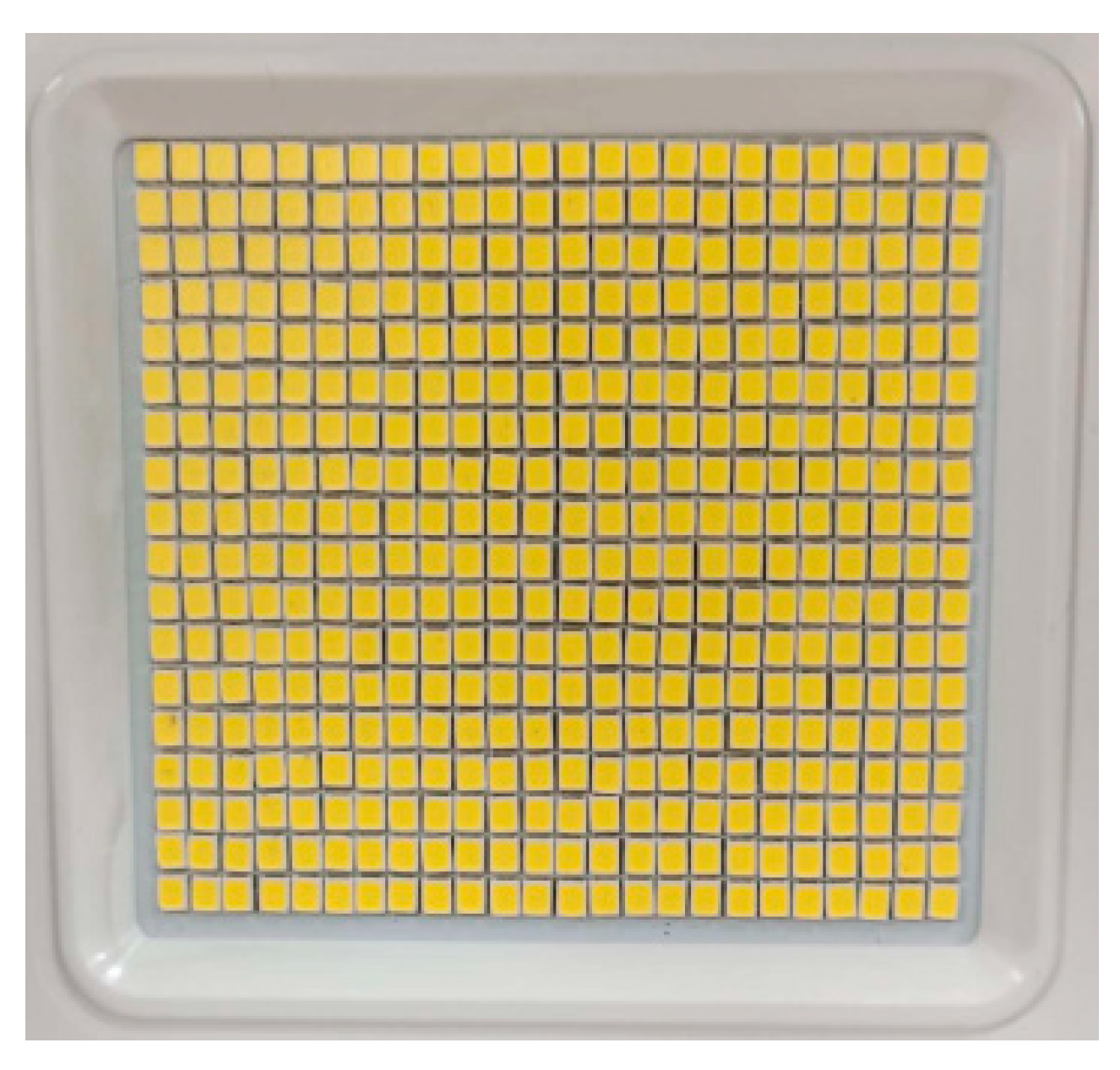
The proposed LED Counter Beam Light (CBL) consisted of a set of 45 mm × 40 mm white light LED array module shown in
Figure 1. The Lambertian LED source owns 5000K color temperature and 5700 output lumens while driven by 50W electrical power supply. The concept of the secondary lens design is to have the Lambertian distributed rays guided to be in almost the same way for forming the counter beam. In consequence, as shown in
Figure 2, the initial step of the design is to have the rays toward the left reflected by aluminum coating surface D and then refracted by surface A to the right, which directions can be adjusted through the tilt angle of surface D and the curvatures of surface C and surface A. As to the LED rays toward the right side, they are planned to be refracted by B surface finally and go to the right, which directions can be controlled by the curvatures of surface B and surface E. In consequence, the variables of the lens optimization can include the tilt angle of surface D and the curvatures of surface A, B, C and E. The searching method used for optimization is based on genetic algorithm embedded in Ansys Speos optical software. The workflow of designing the counter beam tunnel lighting to meet the standards of the CIE 88:2004 regulations is shown in
Figure 3. Based on the standards in the CIE 115-1995 regulations, the brightness luminance uniformity U
o and brightness longitudinal luminance uniformity U
L should be more than 0.4 and 0.6, respectively; additionally, the glare factor TI needs to be higher than 15%, and the contrast revealing factor must be higher than 0.6 for production expenses and economic reasons. The tunnel lighting design areas must conform to the categories below:
- (1)
The speed limit of the path into the tunnel is 70 km/h.
- (2)
The stopping distance in the tunnel is 49.4 m.
- (3)
The tunneling is class two, with one-way lanes, and for motor vehicles only.
- (4)
The traffic flow rate in the tunnel is 500–1000 vehicles per hour per lane during the busiest hour.
To meet the above specifications, eight sets of 50 W LED Counter Beam Lights (CBLs) were grouped as one set of 400 W CBLs with an efficacy of 94.64 lm/W and sorted routinely in the threshold region; the layout is shown in
Figure 4,
Figure 5 and
Figure 6. The spacing of the lights was set to 2 m at that point, following a similar pattern until the end of the zone. Through optical simulation experiments in the trial tunnel performed in LiteStar4D, it was shown that the optimized LED light can accomplish a contrast revealing coefficient of 1.03, which is higher than the minimum regulation level of 0.6 for a qualified Counter Beam Light (CBL), and an average street surface luminance (L
av) of 182.76 cd/m
2, which is better than the CIE 88:2004 regulation standard of 181 cd/m
2. Moreover, a luminance light uniformity of 0.89 (regulatory minimum, 0.4), longitudinal luminance light uniformity of 0.99 (regulatory minimum, 0.6), and glare factor of 7.24% (regulatory minimum, 15%) were also obtained with the LED CBLs in the trial tunnel lighting plan. A comparison of the lighting performance between the initially designed LED CBL and the optimized tunnel light in the tunneling threshold region is shown in
Table 1.
During the optics design process, the initial CBL structure was shown in
Figure 7a and its simulated Light Intensity Distribution Curve (LIDC) was shown in
Figure 7c. The target of optimizing the LED Counter Beam Light was to achieve the contrast revealing factor q
c higher than the lowest regulation level of 0.6 (0.2 for symmetry light formation or 0.6 for a counter beam luminous systems) in the trial tunnel shown in
Figure 4, where 400W Counter Beam Lights (CBL) were set repeatedly with 2 meters spacing along the tunnel road, as shown in
Figure 5. At the start, the initial design can only yield q
c and TI to be 0.36 and 19.96%, respectively, which are far away the requirements of CIE regulation. Through hundreds of computing iterations by Ansys Speos software, the optimized secondary lens was accomplished and shown in
Figure 7b, which LIDC was shown in
Figure 7d, directed LED light pass through its outer curved surfaces—the surface A and the surface B, which radius R
a = 262 mm and R
b = 116 mm, respectively. The inner curved surface C with radius R
c = 40 mm was responsible for refracting its incident LED rays to surface D and then reflecting to surface A, so as to generate the 1763 lumens output beam pattern as shown in
Figure 8. As to the inner curved surface E of the lens, it was with radius R
E = 90 mm and in charge of refracting its incident rays to surface B, which 2969 lumens output beam pattern was shown in
Figure 9. The output light came from surface A and surface B resulted in the 4732 lumens output beam pattern of the optimized LED light, as shown in
Figure 6d, which information was saved as the far field source file for serving as the input into tunnel lighting software LiteStar 4D for analysis and evaluation. Based on the above simulation data, it can be estimated that the optical efficiency and the efficacy of the optimized LED CBL was 83% (4732 lm/5700 lm) and 94.64 lm/W (4732 lm/50 W), respectively.
The tunnel worked on in this research is situated in the north of Taiwan; its entrance is shown in
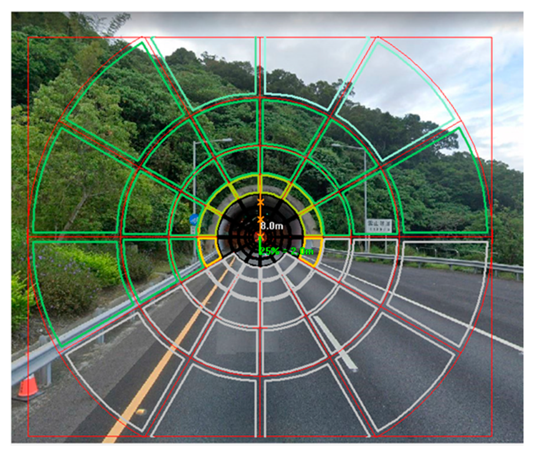
Figure 10. The calculated tunnel details are as follows: a highway tunnel, with two one-way bores; two roadways, each 3.75 m in width; total absolute width, 10 m; roof tallness, 8.05 m; and length of the road tunnel > 500 m. The tunneling direction is south to north. The amount of lighting needed inside a passage is reliant on the level of ambient lighting at which visibility for the driver is conceivable at the passage’s approach and inside. To achieve this, the lighting of a tunnel is divided into specific zones, such as the threshold region and transition region. Using the Holladay–Stiles formula, the equivalent veiling luminance
can be determined to figure out the minimum entry port luminance L
th by using a graphical method embedded in the LiteStar 4D software (Milan, Italy, OxyTech), as shown in
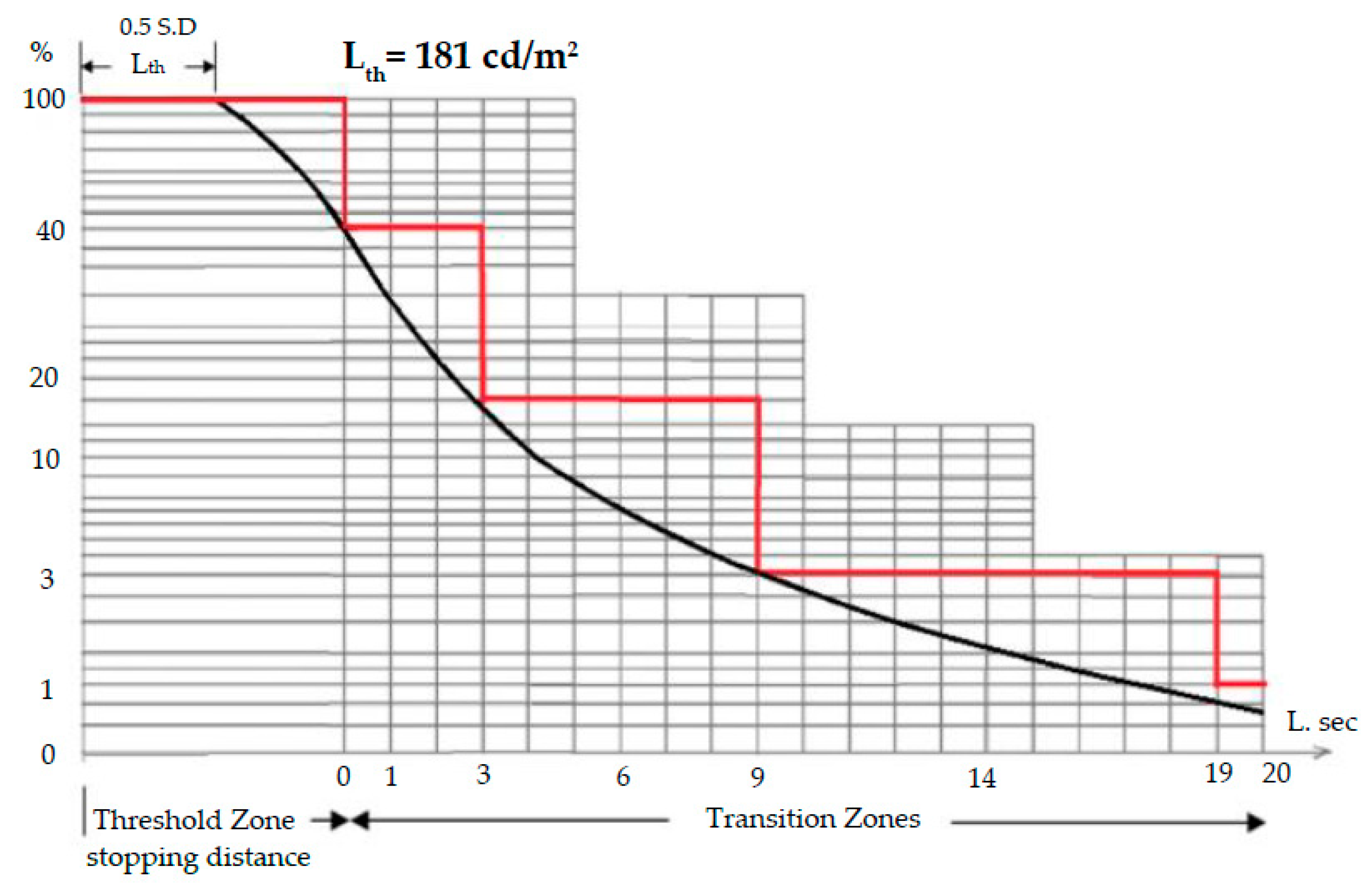
Figure 11. The overlay lines and sections were identified with the Holladay–Stiles method, determining the luminance reduction curve and a required minimum luminance at the entrance
= 181 cd/m
2, as shown by the black curve in
Figure 12.
3. Prototyping and Optical Measurements of Optimized LED CBL
To show that the optimized LED CBL enables the tunnel lighting to satisfy the CIE 88:2004 specialized standards, a secondary lens made of PMMA (Poly (methyl methacrylate),
n = 1.49, melting point = 130–140 °C) was prototyped according to the design shown in
Figure 6. The fixed set of modern CBLs, an approximately 5700-lumen LED array driven by 50 W of electrical power, was as denoted in
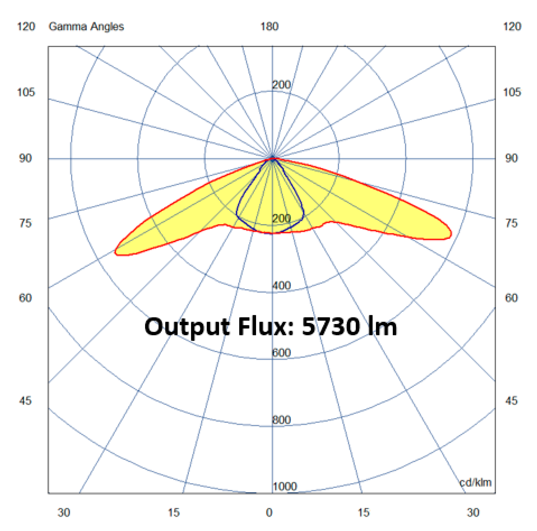
Figure 13a,b. Measurements were taken using an imaging goniophotometer (Radiant Imaging Co. Ltd.) to obtain the intensity distribution, which is shown in
Figure 14 and its near source file. Its output power was adjusted to 4732 lumens based on the simulation results. Therefore, the light efficacy and luminaire efficiency of the LED CBL were 94.64% (4732 lumens/50 W) and 83% (4732 lumens/5700 lumens), respectively. Thereafter, in place of the original simulation source file, the measured optimized tunneling light LED CBL pattern was loaded into LiteStar4D based on the layout shown in
Figure 5,
Figure 6 and
Figure 7; the output reports show that the q
c is 1.38 (>0.6), which means that the optimized LED CBL can function as a counter beam illuminator and be used to illuminate the tunnel in reality. The tunnel lighting evaluation items include
, the average road tunnel surface brightness;
, the brightness uniformity;
, the longitudinal luminance, which the optimized tunnel light LED CBL design and its prototype yield respectively from the tunnel light LED CBL test were both recorded as shown in
Table 2, and the difference in light performance was analyzed.
To exhibit the benefits of the improved LED CBL, the 400 W High-Pressure Sodium (HPS) tunnel lights produced by Innotek Co., Ltd. (Seoul, Korea) and General Electric (GE) Co., Ltd. (Boston, MA, USA), usually used in tunnels in Taiwan, were tested in the trial tunnel lighting plan, to compare their performance in the threshold zone. The measured intensity distributions of these tunnel lights with OSRAM 400 W HPS lamps of 51,000 lumens are shown in
Figure 15 and
Figure 16, respectively. The output powers of Innotek’s fixture and GE’s (GE177743) were measured as 35,843 lumens (luminaire efficiency: 35,843/51,000 = 70.3%) and 36,865 lumens (luminaire efficiency: 36,865/51,000 = 72.2%), respectively, and the light efficacy was calculated as 35,843/400 = 89.6 lumens/W and 36,865/400 = 92.16 lumens/W. Two conventional LED lights (50 W/5000 lumens) provided by LIGITEK Co. Ltd. were also measured and compared: one was the LG-CMTA-2002 LED street light, and the other was the LG-SSL048-12D LED road light; their intensity distributions are shown in
Figure 17 and
Figure 18, respectively. Under the same arrangement with 2 m spacing along each tunnel lane and the same total consumption of electrical power, the lighting performance of the optimized LED CBL light, the commercial 400 W Sodium tunnel lights, and the two LED lights provided by LIGITEK Co. Ltd. were compared in the threshold region, as presented in
Table 3. According to the resulting data listed in
Table 3, it can be observed that both commercial HPS lights were inferior to the proposed LED CBLs in terms of the tunnel road surface luminance L
av and contrast revealing coefficient q
c; furthermore, they failed to meet the CIE 88:2004 regulation standards. In addition, the proposed LED light was shown to be able to qualify as a CBL according to the standards, with a contrast revealing coefficient q
c of 1.38, above the minimum regulatory level of 0.6. The accomplished average road surface luminance (L
av) of 184.5 cd/m
2 was higher than the 114 and 137.64 cd/m
2 provided by the commercial HPS tunnel lights and the 181 cd/m
2 minimum stipulated in the CIE 88:2004 regulations. The yielded luminance uniformity of 0.7 (regulatory minimum, 0.4), longitudinal luminance uniformity for the tunnel of 0.94 (regulatory minimum, 0.6), and glare factor of 7.04% (regulatory minimum, 15%) were also above the CIE standards. As for the two conventional LED lights compared, their beam patterns did not result in tunnel lighting with qualifying contrast coefficients or glare factors, as shown in
Table 3. Therefore, among the five lights, only the proposed LED CBL can meet all of the CIE 88:2004 regulatory requirements for the trial tunnel lighting scheme.
4. Discussion and Conclusions
To improve driving safety and lighting efficiency, an LED Counter Beam Light (CBL) was proposed for use in a tunnel lighting plan to meet the CIE 88:2004 regulations. We proved that the tunneling lighting project could meet the international CIE standards with an appropriate arrangement of the LED CBLs on the ceiling of the trial tunnel, using LiteStar 4D lighting simulations. Based on the simulation results, the new counter beam can produce an average road surface brightness of 182.76 cd/m2 (the regulatory minimum is 181 cd/m2), brightness luminous uniformity of 0.89 (regulatory minimum, 0.4), brightness uniformity for the longitudinal UL of 0.99 (regulatory minimum, 0.6), and glare factor of 7.24% (regulatory minimum, 15%), with a contrast coefficient of 1.03 (regulatory minimum, 0.6) in the threshold region of the tunnel. To prove and demonstrate the feasibility of using the LED CBL in the tunnel, the new design was constructed and measured using an imaging goniophotometer. Based on optical simulations in the software LightTools and LiteStar4D and the IES source files created through the measurements, to verify, calculate, and simulate the new LED CBL sample, the following were achieved: an average surface brightness of the tunnel of 184.2 cd/m2 (regulatory minimum, 181 cd/m2), a brightness uniformity of 0.70 (regulatory minimum, 0.4), a longitudinal brightness uniformity UL of 0.94 (regulatory minimum, 0.6), and a glaring factor of 7.04% (regulatory minimum, 15%). A contrast coefficient of 1.38 (regulatory minimum, 0.6) was obtained in the threshold region. The results show that, both in simulation and in practice, it can be inferred that the proposed tunnel light LED CBL can qualify as a certified Counter Beam Light (CBL) and light the trial tunnel in a way that meets the regulatory standards CIE 88:2004.
To prove the advantages of using the proposed tunnel light LED CBL, commercial tunnel lights with OSRAM Vialox Nav-T Super 400 W/51,000 lm High-Pressure Sodium (HPS) lamps were measured for comparison; the results are shown in
Table 3. The used HPS lamps have an efficacy of 124.5 lm/W (51,000 lm/400 W), conclusively better than the 114 lm/W (5700 lm/50 W) of the LED array source. However, the luminaire efficiencies of these HPS tunnel lights, 72.2 and 70.3%, are both much less than the 83% of the proposed LED CBL. Therefore, the LED CBL has a light efficacy of 94 lumens/W, better than the 89.6 and 92.16 lumens/W that the commercial HPS tunnel lights can provide. The measured light intensity distribution curves shown in
Figure 14,
Figure 15 and
Figure 16 indicate that the optimized tunnel light LED CBL has the strongest light luminous intensity control over 40°~60°, which dominates the luminance intensity in the tunnel for drivers, so the proposed LED CBL results in the best tunnel road surface luminance L
av by comparison. For highway tunnels with speed limits more than 70 km/h, the minimum required luminance L
th at the entrance would be even higher. Therefore, LED CBLs will become even essential in future tunnel lighting development.
Because the used LED array was built by surface mounting technology (SMT), the larger LED array emitting area would cause the secondary lens to fall short of the CIE regulations for tunnel lighting. On the other hand, even chip-on-board (COB) techniques can effectively minimize the LED array size but considering the issues of the life and efficiency of LEDs, LED arrays with more than 80 W of power have still not been commercialized. Therefore, the grouping of multiple LED CBLs is still necessary for achieving higher luminance. If COB LED technology continues to improve, the proposed LED CBL with hundreds of watts of power may be realized in the future, allowing the number of CBLs in the tunnel lighting plan to be reduced.


 ,
, 


