Abstract
Wireless power transfer (WPT) is becoming popular increasingly in stationary electric vehicle (EV) charging. Various coil structures were proposed to improve the coupling characteristics, and polarized couplers have been proven to have better performance. Considering the varying spatial scales of transmitting and receiving, coils will alter the mutual inductance, further affecting the output power and transmission efficiency; therefore, it is crucial to calculate the mutual inductance of polarized couplers with variable offset for WPT system design. However, given the complex structure and the various excitation conditions of polarized couplers, the solving process based on the finite element model is time-consuming and resource intensive, therefore it is necessary to develop analytical models of mutual inductance for polarized couplers under misalignment. In this paper, the analytical models of the two commonly used polarized couplers with a Double-D polarized coil (DDP) or a Bipolar polarized coil (BP) on both sides under misalignment along any direction under different excitation conditions are proposed based on dual Fourier transformation. The mutual inductance characteristics of the two polarized couplers under misalignment can be investigated based on the proposed analytical models and finite element models, respectively. The results show that the mutual inductance of BP-BP coupler with in-phase current excitation mode is greater and more stable, and the method based on the analytical model is timesaving. Finally, the prototype of the WPT system with the two polarized couplers has been built, and experiments have also been carried out to verify the accuracy of the analytical models.
1. Introduction
Owing to the advantages of convenience and safety [1,2,3,4], wireless power transfer (WPT) is becoming increasingly popular in stationary electric vehicle (EV) charging. A typical WPT stationary charging system usually consists of a transmitting side and receiving side. To improve the charging efficiency, the transmitting side and the receiving side are usually designed to resonate at the operating frequency [5,6,7,8,9,10,11]. Magnetic couplers are key components of the WPT system; the power is delivered from the transmitting coils to the receiving coils across tens of centimeters. The performance of the magnetic coupler determines the overall feasibility of a complete system. Therefore, the modeling and analysis of magnetic coupling coils are helpful to speed up the design process of a WPT system.
In order to enhance the coupling characteristics, various magnetic coil structures had been developed and analyzed for electric vehicle wireless charging applications in the previous work. Based on their ability to generate or couple different flux patterns, these coil structures can be divided into the non-polarized coil and polarized coil. A non-polarized coil ideally generates and couples a flux pattern that is symmetric around the centre of the coil, but the term is still used for the coil designs where the fields are directionally symmetric around the coil centre though the strength of the field might be different along different angles around the centre. On the other hand a polarized coil generates and couples a flux pattern in which the flux flows dominantly along one dimension of the coil only i.e., either length or width of the coil [12]. The influences of the key design parameters on coupled power were investigated and the circular magnetic structure was optimized in [13]. The design of a disc structure for the energy transmission over an air gap of several hundred millimeters was investigated in [14]. The loosely coupled transformer design method to minimize the EMF in the concerned area was presented in [15]. However, the above research focused on the design and optimization of the non-polarized coil. To further improve the flexibility and efficiency of the coupling coil, a variety of polarized coil structures had been proposed and analyzed. A new polarized coupler structure called the Double-D coupler was presented, and the transmission characteristics of the circular coupler and the Double-D coupler were compared in [16]. An optimization structure was proposed in the Double-D receiving coils by adding an extra coil, called the Quadrature coil, and the transmission characteristics of the DD-DDQ coupler were studied in [17]. Another polarized decoupled coupler called the Bipolar Pad (BPP) was proposed, and the uncompensated power characteristics of various multiple decoupled coil structures were investigated in detail in [12,18]. A compact and efficient bipolar coupler for wireless power chargers was proposed, and the coupling coefficient characteristics of the coils under misalignment were studied in [19]. A new magnetic structure called Tripolar Pad was developed as a primary pad, and the coupling coefficient characteristics of the Tripolar pads and circular pads under misalignment were compared in [20,21]. It can be concluded that a polarized coupler usually have larger mutual inductance and larger charging zone than the a non-polarized coupler. Moreover, in the application of electric vehicle wireless charging, the misalignment between the transmitting coil and the receiving coil may occur in any direction, and the excitation conditions of the polarized couplers may change to obtain better coupling characteristics. These two factors may alter the mutual inductance of the coupler and further cause the fluctuation of transmission power and efficiency. Therefore, it is critical to calculate the mutual inductance of different polarized couplers with variable offset and under different excitation conditions for the WPT system design, and the two commonly used polarized couplers DD-DD and BPP-BPP are focused on this paper.
Meanwhile, given the complex structure and the various excitation conditions of the two polarized couplers, the solving process of the mutual inductance based on finite element models is increasingly time-consuming and resource intensive, the analytical model is a more flexible, convenient and economic tool for coupler design. Various analytical models of mutual inductance for different coil structures have been proposed in the previous work. The mutual inductance and self-inductance of circular coils were analyzed by the method of Bessel and Struve functions in [22]. New analytic formulas for determining the mutual inductance and the axial magnetic force between two coaxial coils were presented in [23]. The analytical calculations of magnetic parameters (field, force, torque, stiffness) in cylindrical magnets and coils were proposed by Biot-Savart law in [24]. The mutual inductance characteristics between two circular coils in lateral and angular misalignment were investigated in [25].The analytical models of the square and circular planar coils with a ferrite layer were calculated by the method of Fourier-Bessel transformation and Dual-Fourier transformation in [26].Unfortunately, the above researches mainly focused on the modeling of non-polarized couplers under misalignment, none of them considered the polarized couplers under misalignment and under different excitation conditions. Therefore, it is necessary to put forward the analytical models of the mutual inductance for the two polarized couplers under misalignment and under different excitation conditions, and investigate the mutual inductance characteristics of the two polarized couplers under misalignment based on the analytical models.
In this paper, the two commonly used polarized couplers DDP-DDP and BP-BP are considered. The analytical models of the two polarized couplers under misalignment along any direction and under different excitation conditions are proposed based on dual Fourier transformation. Furthermore, the mutual inductance characteristics of the two polarized couplers under misalignment along different directions are investigated by the proposed analytical models and the finite element models, respectively, and the computational costs of the two methods are compared. Finally, the prototypes of the WPT system and the two polarized couplers with an area of 500 mm × 300 mm have been built and the measurements were taken to validate the accuracy of the analytical models.
2. Analytical Models of the DDP-DDP and BP-BP Couplers under Misalignment
In the application of electric vehicle wireless charging, due to the variable mutual inductance of the coupler under misalignment, the output power and transmission efficiency will fluctuate; it is necessary to obtain the analytical models of the mutual inductance for different coil structures under misalignment. In this section, the analytical models of the DDP-DDP and BP-BP couplers under misalignment along any direction and under different excitation conditions are developed, and the opposite phase currents and in-phase currents excitation modes are considered.
2.1. Mutual Inductance of the DDP-DDP Coupler under Misalignment
The basic structure of the DDP-DDP filamentary coupler in Cartesian coordinates is shown in Figure 1. The lower Double-D filamentary turn represents the transmitting coils, which are driven by the harmonic current Iejωt. The upper Double-D filamentary coil represents the receiving coils. The whole area can be divided into two regions: region 1 is the area under the transmitting filamentary turn, and region 2 is the area above the transmitting filamentary turn. The mediums corresponding to the two regions are air, and μ0 and σ0 are relative permeability and conductivity, respectively. The transmitting filamentary turn and receiving filamentary turn are located at z = z1 and z = z1 + h planes, and the dimensions of the two filamentary turns on both sides are indicated in Figure 1,where the six sides of the transmitting filamentary turn are located at y’ = c1, y’ = c2, y’ = −c1, y’ = −c2, x’ = c3, x’ = −c3,respectively, and the six sides of the receiving coil in alignment are located at y’ = d1, y’ = d2, y’ = −d1, y’ = −d2, x’ = d3, x’ = −d3, respectively.
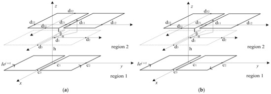
Figure 1.
Layout of the dual Double-D(DD–DD) filamentary coupler under misalignment. (a) Driven by the opposite phase currents; (b)Driven by the in-phase currents.
2.1.1. DDP-DDP Coupler Driven by the Opposite Phase Currents
When the two individual coils of the transmitting filamentary turn are driven by the opposite phase currents, the analytical model can be regarded as a magnetoquasistatic system, such as in Figure 1a. The magnetic flux density B generated by the currents of the transmitting filamentary turn can be expressed as Equation (1), and the vector potential A of arbitrary point p(x, y, z) as Equation (2) can be derived by integrating the current density J1(x’, y’, z’) along the wire [27].
where J1(x’, y’, z’) is the current density, and J1(x’, y’, z’)dv is the current element along the turn. R is the distance from arbitrary point p(x, y, z) to source point (x’, y’, z’), defined in Equation (3):
For solving the above Equations, the dual Fourier transformation and its inverse methods are used as follows, where and are integration variables [28]:
Appling Fourier transformation to (1), the magnetic flux density B can be obtained as
Appling Fourier transformation to (2), the magnetic vector potential can be derived as
where .
Considering the current distribution of the DDP transmitting filamentary coil driven by the opposite phase currents in Figure 1a, the wire paralleled to the x-axis consists of four parts, which satisfy y’ = c1, x’ = [−c3, c3], J1(x’, y’, z’) = I; y’ = c2, x’ = [c3, −c3], J1(x’, y’, z’) = I; y’ = −c1, x’ = [−c3, c3], J1(x’, y’, z’) = I; y’ = −c2, x’ = [c3, −c3], J1(x’, y’, z’) = I, respectively, so the x component of vector potential ax can be obtained as
Similarly, the wire paralleled to the y-axis also consists of four parts, which satisfy x’ = c3, y’ = [c1, c2] and y’ = [−c1,−c2], J1(x’, y’, z’) = I; x’ = −c3, y’ = [c2, c1] and y’ = [−c2, −c1], J1(x’, y’, z’) = I, respectively, and the y component of vector potential ay can be given as follows:
Substituting (8) and (9) into (6), considering that only the z component of the magnetic flux density contributes to the mutual inductance M between transmitting filamentary turn and receiving filamentary turn, and the receiving filamentary turn is located in region 2, and the z components of incident magnetic flux density in region 2 can be written as follows:
According to Fourier inverse transformation (5), the z component of magnetic flux density in region 2 can also be expressed as
When the receiving filamentary turn displace along one direction, the six sides of the receiving coil under misalignment are located at y’ = d11, y’ = d12, y’ = d21, y’ = d22, x’ = d31, x’ = d32, respectively, as shown in Figure 1a, where L is the displacement along any direction, β is the angle between displacement direction and the x–y plane, α is the angle between the direction of the component of the displacement in the x–y plane and the x-axis, and the position variable of the receiving turn can be expressed as
Mutual inductance can be obtained by Equation (13) [27], substituting (11) and (12) into (13):
The mutual inductance between the two filamentary turns driven by the opposite phase currents can be obtained. When the number of turns of the transmitting coil and receiving coil are N1 and N2, according to the superposition principle, the mutual inductance of the DDP-DDP coupler in the opposite phase excitation mode can be derived as (14), where s1 and s2 are the line spacing of the transmitting coils and the receiving coils, respectively, and p and q represent the p turn of the transmitting coils and the q turn of the receiving coils, respectively.
2.1.2. DDP-DDP Coupler Driven by the In-Phase Currents
When the two individual coils of the DDP transmitting coil are driven by in-phase currents, the analytical model can be regarded as a magnetoquasistatic system (Figure 1b).
Considering the current distribution of the DDP transmitting filamentary coil driven by the in-phase currents in Figure 2, the wire parallel to x-axis consists of four parts, which satisfy y’ = c1, x’ = [c3, −c3], J1(x’, y’, z’) = I; y’ = c2, x’ = [−c3, c3], J1(x’, y’, z’) = I; y’ = −c1, x’ = [−c3, c3], J1(x’, y’, z’) = I; y’ = −c2, x’ = [c3, −c3], J1(x’, y’, z’) = I, respectively, so the x component of vector potential ax can be obtained as
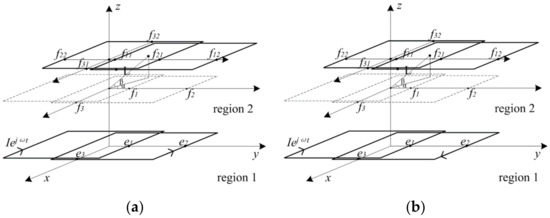
Figure 2.
Layout of the dual Bipolar (BPP-BPP) filamentary coupler under misalignment. (a) Driven by the opposite phase currents; (b) Driven by the in-phase currents.
Similarly, the wire parallel to the y-axis also consists of four parts, which satisfy x’ = c3,y’ = [c2 c1] and y’ = [−c1, −c2], J1(x’, y’, z’) = I; x’ = −c3, y’ = [c1, c2] and y’ = [−c2, −c1], J1(x’, y’, z’) = I, respectively, and the y component of vector potential ay can be given as follow
Substituting (15) and (16) into (6) and (13), according to the superposition principle, the mutual inductance of the DDP-DDP coupler in the in-phase excitation mode can be derived as Equation (17).
2.2. Mutual Inductance of the BP-BP Coupler under Misalignment
The basic structure of the BPP-BPP filamentary coupler in Cartesian coordinates is shown in Figure 2. The single-sided bipolar coil consists of two identical, partially overlapped and mutually decoupled coils. The lower bipolar filamentary turn represents the transmitting coils, which is driven by the harmonic current Iejωt, and the current density along the transmitting turn is J2(x’, y’, z’). The upper bipolar filamentary turn represents the receiving coils. The dimensions of the two filamentary turns on both sides are indicated in Figure 2. The opposite phase driving currents and in-phase driving currents are discussed in this section.
2.2.1. BPP-BPP Coupler Driven by the Opposite Phase Currents
For Bipolar transmitting filamentary turns driven by the opposite phase currents, the current distribution is shown in Figure 2a. The current density distribution along the wire parallel to the x-axis satisfy y’ = e1, x’ = [−e3, e3], J1(x’, y’, z’) = I; y’ = e2, x’ = [e3, −e3], J1(x’, y’, z’) = I; y’ = −e1, x’ = [−e3, e3], J1(x’, y’, z’) = I; y’ = −e2, x’ = [e3, −e3], J1(x’, y’, z’) = I, so the x component of vector potential ax can be obtained as follows:
The current density distribution along the wire parallel to the y-axis satisfies x’ = e3, y’ = [e1, −e2] and y’ = [−e1,e2], J1(x’, y’, z’) = I; x’ = −e3, y’ = [−e2, e1] and y’ = [e2, −e1],J1(x’, y’, z’) = I; the y component of vector potential can be given as
When the receiving filamentary turns displace along one direction, the six sides of the receiving coil under misalignment are located at y’ = f11, y’ = f12, y’ = f21, y’ = f22, x’ = f31, x’ = f32, respectively, as shown in Figure 2a, where L is the displacement along any direction, β is the angle between displacement direction and x–y plane, α is the angle between the direction of the component of the displacement in the x–y plane and the x-axis, and the position variable of the receiving turn can be expressed as
Substituting (18)–(20) into (6) and (13), according to the superposition principle, the mutual inductance of the BP-BP coupler in the opposite phase currents excitation can be derived as Equation (21).
2.2.2. BP-BP Coupler Driven by the In-Phase Currents
For bipolar transmitting filamentary turns driven by the in-phase currents, the current distribution is considered (Figure 2b). The current density distribution along the wire parallel to the x-axis satisfy y’ = e1,x’ = [−e3, e3], J1(x’, y’, z’) = I; y’ = e2, x’ = [−e3, e3], J1(x’, y’, z’) = I; y’ = −e1, x’ = [e3, −e3], J1(x’, y’, z’) = I; y’ = −e2, x’ = [e3, −e3], J1(x’, y’, z’) = I, so the x component of vector potential ax can be obtained as follows:
The current density distribution along the wire parallel to the y-axis satisfy x’ = e3, y’ = [e1, −e2] and y’ = [−e1, e2], J1(x’, y’, z’) = I; x’ = −e3, y’ = [−e2, e1] and y’ = [e2, −e1], J1(x’, y’, z’) = I, so the y component of vector potential can be given as follows:
Substituting (22) (23) (20) into (6) and (13), according to the superposition principle, the mutual inductance of the BP-BP coupler in the in-phase currents excitation can be derived as Equation (24).
It should be noted that the mutual inductance characteristics of the DDP-DDP and BP-BP couplers under misalignment along any direction can be easily obtained by the above analytical models, as long as the values of L, α, β are modified.
3. Comparison of the Mutual Inductance Characteristics for the DDP-DDP and BP-BP Couplers Based on the Analytical Models
Based on the analytical models proposed in the Section 2, the mutual inductance characteristics of the DDP-DDP and BP-BP couplers under misalignment in different directions and different excitation modes were investigated, comparing with the results of the finite element simulations. The computational cost of the two methods was compared, the displacements of the receiving coils along the x-axis, y-axis and z-axis directions were focused, and the in-phase current excitation modes and the opposite phase current excitation modes are discussed. The results of the analytical model were obtained by the numerically evaluate integral, the value of the maximum number of intervals (650) was used, and the integration domain was defined as (−Inf, Inf) and the finite element models (FEM) of the DDP-DDP and BP-BP couplers under misalignment are established based on the software JMAG (Figure 3).To fairly compare the analytical models and the finite element models, the parameters of the two models for the two polarized couplers are shown in Table 1 and Table 2. It should be noted that the position coordinates are for the outermost turn of the coils on both sides, and the parameters of the analytical models are 2 mm smaller than those of the finite element model because the width of the litz wire was 4 mm. Considering the trade-off between calculation time and calculation accuracy, the mesh of coil area and air area were 4 mm and 40 mm, respectively.
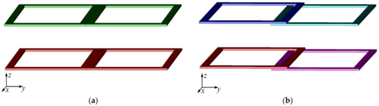
Figure 3.
Finite element models of the polarized couplers (a) DDP-DDP coupler (b) BP-BP coupler.

Table 1.
Parameters of the analytical models for the two polarized couplers.
Table 2.
Parameters of the finite element model for the two polarized couplers.
3.1. Mutual Inductances of the Two Polarized CouplersUnder Misalignment in Different Directions
3.1.1. Misalignment along the x-Axis
In this part, the transmitting coils of DDP-DDP and BP-BP couplers were excited by the in-phase and opposite phase currents. The receiving coils moved along the x-axis; the displacement along the x-axis, L, was considered as a variable, which ranged from L = 0 mm to L = 300 mm and the interval was 50 mm.
The mutual inductances of the two polarized couplers under misalignment along the x-axis and in different excitation modes are shown in Figure 4. The lines of different shapes correspond to the mutual inductances of DDP-DDP and BP-BP couplers based on the analytical models, and the points of different shapes correspond to those obtained by finite element simulations. It can be observed that the mutual inductances of the two coil structures decreased gradually with the increase in the displacement along the x-axis in both excitation modes. The mutual inductance of the BP-BP coupler under the in-phase current excitation condition produced the largest value when the displacement was less than 160 mm, but the mutual inductance of the two polarized couplers in the opposite phase currents excitation condition decreased more slowly.
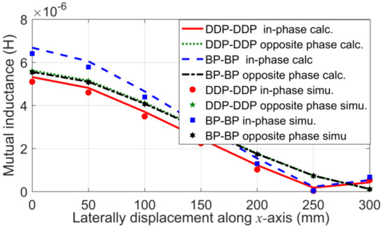
Figure 4.
Mutual inductance of coils under misalignment along the x-axis and in different excitation modes.
3.1.2. Misalignment along the y-Axis
When the receiving coils moved along the y-axis, the displacement of the receiving coils along the y-axis, L, was considered as a variable, varying from L = 0 mm to L = 500 mm and the interval was 50 mm.
The mutual inductances of the two polarized couplers under misalignment along the y-axis and in different excitation modes are shown in Figure 5. This shows that with the increase in the displacement along the y-axis, the mutual inductances of the two coil structures in the in-phase current excitation mode decreased gradually, but the mutual inductances in the opposite phase current excitation mode first decreased, then increased, and finally decreased. It can also be observed that the mutual inductance of the BPP-BPP coupler in-phase currents excitation condition was greater when the displacement was less than 250 mm. However, the mutual inductances of coils under the opposite phase currents excitation condition had greater fluctuation.
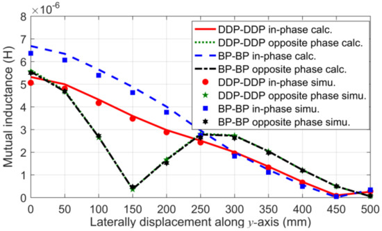
Figure 5.
Mutual inductance of coils under misalignment along the y-axis and in different excitation modes.
3.1.3. Misalignment along the z-Axis
In this part, the receiving coils moved along the z-axis. The vertical distance between two coils was considered as a variable, varying from 50 mm to 300 mm and the interval was 50 mm.
The mutual inductances of the two coil structures in different excitation modes as the receiving coils moved in the z-axis direction are shown in Figure 6. It can be observed that the mutual inductances of the two coil structures decreased gradually with the increase in the displacement along the z-axis in both excitation modes. It can also be observed that the mutual inductance of the BP-BP coupler in the in-phase current excitation mode was always greater than that of other conditions, and the decreasing speed of the mutual inductance in the in-phase current excitation mode was less than that of the opposite phase current excitation mode.
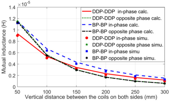
Figure 6.
Mutual inductance of coils under misalignment along the z-axis and in different excitation modes.
The mutual inductance obtained by the analytical model and the finite element simulations show a great agreement under the same parameters; it can be observed that the BP-BP coupler in the in-phase current excitation mode achieved greater mutual inductance for the misalignment along the x-, y- and z-axes, and the two polarized couplers in the in-phase current excitation mode have a small mutual inductance fluctuation for the misalignment along y- and z-axes, but it had a large mutual inductance fluctuation for the misalignment along the x-axis.
3.2. Comparison of Computational Costs
For the DDP-DDP and BP-BP couplers in the in-phase current excitation mode and under the misalignment in the x-axis direction, the computational costs of the analytical models and the finite element models were compared. Both of the calculations are operated in a computer equipped with Intel Core processors featuring a 3.3-GHz clock frequency and 4GB RAM memory. The total calculation times for the seven locations based on the two models are shown in Table 3.
Table 3.
Computational cost of the two modes under misalignment along the x-axis.
It can be inferred that mutual inductance of the polarized couplers under misalignment along the x-axis can be obtained more quickly based on the analytical models proposed in this paper. The same conclusion can be obtained for the displacements along the y-axis and z-axis. It should be noted that when the mesh of the finite element model was larger, the calculation time was shortened, but the calculation accuracy was reduced. By comparing the computational cost of the methods based on the analytical models and the finite element models, it can be concluded that the method based on the analytical model was timesaving.
4. Experimental Results and Discussion
To validate the accuracy of the proposed analytical models and compare the performance of the DDP-DDP and BP-BP couplers in the electric vehicle wireless charging application, the experimental prototype of the WPT system with the two polarized couplers has been built, and is shown in Figure 7. The mutual inductances of the two polarized couplers under misalignment are assessed in this section. According to the SAE J2954 wireless charging standard for EVs, the parameters of the low power scale experimental setup and the misalignment ranges along different directions are shown in Table 4.
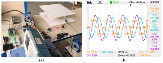
Figure 7.
Prototype of the wireless power transfer (WPT) system with the polarized coupler. (a) Experimental setup; (b) Waveforms of input voltage and currents on both sides.
Table 4.
Parameters of the experimental setup.
4.1. Experimental Setup
As shown in Figure 7a, the experimental setup consisted of a full bridge inverter, compensation circuits, the polarized couplers, a rectifier, and DC load. The full bridge inverter was implemented with four Silicon Carbide MOSFETs. Series compensation topology was adopted on both sides of the WPT system. Both of the DDP-DDP and BP-BP couplers were wound by litz wire composed of 800 strands with 0.1 mm strand diameter—the skin effect could be neglected when the frequency was 85 kHz. The two individual coils within the single side of the polarized coil in the in-phase current excitation mode could be wound as two separate planar coils with two same poles and two accessible terminals, and the two individual coils in the opposite phase current excitation mode could be wound with two opposite poles and two accessible terminals.
When the WPT system operated under the parameters as shown in Table 4, the resultant waveforms of the input AC voltage and currents of coils on both sides are shown in Figure 7b. The varying spatial scales of the coils on both sides will alter the mutual inductance, further causing fluctuations in the currents of coils and the output power. Therefore, the mutual inductance characteristics of the two polarized couplers under misalignment along the x-, y-, and z-axes are verified by experiments in the next section.
4.2. Experimental Results of the Mutual Inductances for the Two Polarized Couplers under Misalignment
The mutual inductances of DDP-DDP and BP-BP couplers under misalignment along the x-axis, y-axis and z-axis were measured by TH2827A LCR Meter (20 Hz–300 kHz), as shown in Figure 8, Figure 9 and Figure 10, respectively, comparing with the calculation results based on the analytical models under the identical settings. The lines of different shapes in the figures correspond to the mutual inductances of DDP-DDP and BPP-BPP couplers based on the analytical models, and the points of different shapes represent the experimental results.
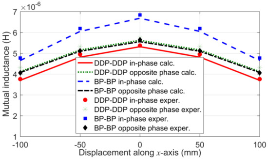
Figure 8.
Experimental results and calculation results of mutual inductance for the two polarized couplers under misalignment along the x-axis.
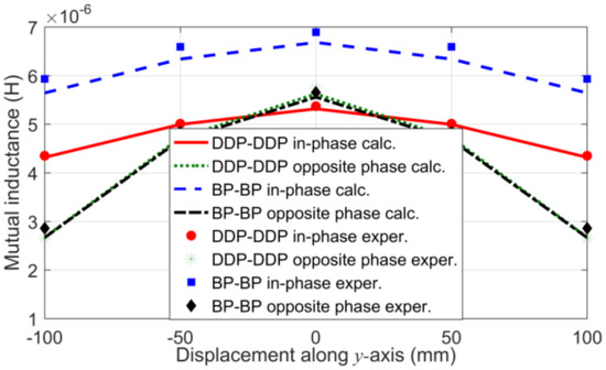
Figure 9.
Experimental results and calculation results of mutual inductance for the two polarized couplers under misalignment along the y-axis.
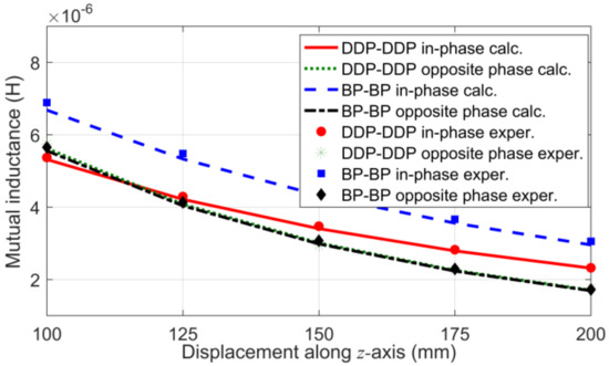
Figure 10.
Experimental results and calculation results of mutual inductance for the two polarized couplers under misalignment along the z-axis.
Figure 8 shows that in the displacement range along the x-axis, the mutual inductance of the BPP-BPP coupler in the in-phase current excitation mode produced the largest value. The decrease rates of the mutual inductances for the DDP-DDP coupler in the two excitation modes were 30% and 25%, respectively. The counterparts of the BPP-BPP coupler were 30% and 28%, respectively. In Figure 9, it can be observed that in the displacement range along the y-axis, the mutual inductance of the BPP-BPP coupler in the in-phase current excitation mode was larger than that of other cases. The decrease rates of mutual inductances for the DDP-DDP coupler in the two excitation modes were 19% and 54%, respectively. The counterparts of the BPP-BPP coupler were 14% and 49%, respectively. Figure 10 shows that the mutual inductance of the BPP-BPP coupler in the in-phase current excitation mode produced the largest value in the displacement range along the z-axis. The decrease rates of mutual inductances for DDP-DDP coupler in the two excitation modes were 57% and 69%, respectively. The counterparts of the BP-BP coupler were 56% and 70%, respectively. It was verified that the BPP-BPP coupler in the in-phase current excitation mode achieved greater mutual inductance for the misalignment along the x-, y- and z-axes; the two polarized couplers in the in-phase current excitation mode had a small mutual inductance fluctuation for the misalignment along the y- and z- axes, but had a large mutual inductance fluctuation for the misalignment along the x-axis. In the design of the WPT system, we considered the trade-off between the magnitude and fluctuation of mutual inductance, and chose the appropriate polarized coupler.
Furthermore, the experimental results are well in agreement with the theoretical analysis, verifying the accuracy of the analytical models. It should be noted that the mutual inductance characteristics of the two polarized couplers under misalignment in x-, y-, and z-axis directions were analyzed in simulations and experiments, but the mutual inductance characteristics under misalignment in any direction could be analyzed based on the analytical models proposed in this paper.
5. Conclusions
In this paper, the analytical models of the two commonly used polarized couplers DDP-DDP and BP-BP under misalignment in any direction were developed based on dual Fourier transformation, and the mutual inductance characteristics of the two polarized couplers under misalignment in different directions and different excitation modes can be investigated based on the proposed analytical models and the finite element models. The results show that in the electric vehicle wireless charging application, the BP-BP coupler in the in-phase current excitation mode achieved greater mutual inductance for the misalignment in the x-, y- and z-axes direction, the two polarized couplers in the in-phase current excitation mode had a small mutual inductance fluctuation for the misalignment along the y- and z-axes, but had a large mutual inductance fluctuation for the misalignment along the x-axis. The computational cost of the analytical models and the finite element models were compared under the same parameters. The results show that the method based on the analytical models was faster to analyze the mutual inductance characteristics of the polarized couplers. The experimental results are well in agreement with the theoretical analysis, verifying the accuracy of the analytical model. It should be noted that the numerical calculation method proposed in this paper is not only suitable for the DDP-DDP and BP-BP polarized couplers, but also can be applied to the analysis of other polarized couplers.
Author Contributions
Conceptualization, W.Z.; methodology, W.Z., Z.L. and S.L.; project administration, J.S.; writing—original draft, H.R., Y.Z. and Y.S. All authors have read and agreed to the published version of the manuscript.
Funding
This research received no external funding.
Institutional Review Board Statement
Not applicable.
Informed Consent Statement
Not applicable.
Data Availability Statement
Not applicable.
Acknowledgments
This work was supported in part by the National Natural Science Foundation of China under Grant 51577123.
Conflicts of Interest
The funders had no role in the design of the study; in the collection, analyses, or interpretation of data; in the writing of the manuscript, or in the decision to publish the results.
References
- Hui, S.; Zhong, W.; Lee, C. A critical review of recent progress in mid-range wireless power transfer. IEEE Trans. Power Electron. 2014, 29, 4500–4511. [Google Scholar] [CrossRef]
- Covic, G.A.; Boys, J.T. Modern trends in inductive power transfer for transportation applications. IEEE J. Emerg. Sel. Top. Power Electron. 2013, 1, 28–41. [Google Scholar] [CrossRef]
- Lee, C.; Zhong, W.; Hui, S. Recent progress in mid-range wireless power transfer. In Proceedings of the 2012 IEEE Energy Conversion Congress and Exposition (ECCE), Raleigh, NC, USA, 15–20 September 2012; pp. 3819–3824. [Google Scholar]
- Choi, S.; Gu, B.; Jeong, S.; Rim, C. Advances in wireless power transfer systems for roadway-powered electric vehicles. IEEE J. Emerg. Sel. Top. Power Electron. 2015, 3, 18–36. [Google Scholar] [CrossRef]
- Li, X.; Zhang, H.; Peng, F.; Li, Y.; Yang, T.; Wang, B.; Fang, D. A wireless magnetic resonance energy transfer system for micro implantable medical sensors. Sensors 2012, 12, 10292–10308. [Google Scholar] [CrossRef] [PubMed]
- Puccetti, G.; Stevens, C.; Reggiani, U.; Sandrolini, L. Experimental and numerical investigation of termination impedance effects in wireless power transfer via metamaterial. Energies 2015, 8, 1882–1895. [Google Scholar] [CrossRef]
- Sun, L.; Tang, H.; Zhang, Y. Determining the frequency for load-independent output current in three-coil wireless power transfer system. Energies 2015, 8, 9719–9730. [Google Scholar] [CrossRef]
- Cheon, S.; Kim, Y.-H.; Kang, S.-Y.; Lee, M.L.; Lee, J.-M.; Zyung, T. Circuit-model-based analysis of a wireless energy-transfer system via coupled magnetic resonances. IEEE Trans. Ind. Electron. 2011, 58, 2906–2914. [Google Scholar] [CrossRef]
- Kiani, M.; Jow, U.M.; Ghovanloo, M. Design and optimization of a 3-coil inductive link for efficient wireless power transmission. IEEE Trans. Biomed. Circuits Syst. 2011, 5, 579–591. [Google Scholar] [CrossRef] [PubMed]
- Ahn, D.; Hong, S. A study on magnetic field repeater in wireless power transfer. IEEE Trans. Ind. Electron. 2013, 60, 360–371. [Google Scholar] [CrossRef]
- Sample, A.P.; Meyer, D.A.; Smith, J.R. Analysis, experimental results, and range adaptation of magnetically coupled resonators for wireless power transfer. IEEE Trans. Ind. Electron. 2011, 58, 544–554. [Google Scholar] [CrossRef]
- Zaheer, A.; Hao, H.; Covic, G.A.; Kacprzak, D. Investigation of multiple decoupled coil primary pad topologies in lumped IPT systems for interoperable electric vehicle charging. IEEE Trans. Power Electron. 2015, 30, 1937–1955. [Google Scholar] [CrossRef]
- Carmeli, M.S.; Castelli-Dezza, F.; Mauri, M.; Foglia, G. Contactless energy transmission system for electrical vehicles batteries charging. In Proceedings of the 2015 International Conference on Clean Electrical Power (ICCEP), Taormina, Italy, 16–18 June 2015; pp. 499–505. [Google Scholar]
- Budhia, M.; Covic, G.A.; Boys, J.T. Design and optimization of circular magnetic structures for lumped inductive power transfer systems. IEEE Trans. Power Electron. 2011, 26, 3096–3108. [Google Scholar] [CrossRef]
- Zhang, W.; White, J.C.; Malhan, R.K.; Mi, C.C. Loosely Coupled Transformer Coil Design to Minimize EMF Radiation in Concerned Areas. IEEE Trans. Veh. Technol. 2016, 65, 4779–4789. [Google Scholar] [CrossRef]
- Budhia, M.; Boys, J.T.; Covic, G.A.; Huang, C.-Y. Development of a single-sided flux magnetic coupler for electric vehicle IPT charging systems. IEEE Trans. Ind. Electron. 2013, 60, 318–328. [Google Scholar] [CrossRef]
- Budhia, M.; Covic, G.A.; Boys, J.T.; Huang, C.-Y. Development and evaluation of single sided flux couplers for contactless electric vehicle charging. In Proceedings of the 2011 IEEE Energy Conversion Congress and Exposition, Phoenix, AZ, USA, 17–22 September 2011; pp. 614–621. [Google Scholar]
- Covic, G.A.; Kissin, M.L.G.; Kacprzak, D.; Clausen, N.; Hao, H. A bipolar primary pad topology for ev stationary charging and high-way power by inductive coupling. In Proceedings of the 2011 IEEE Energy Conversion Congress and Exposition, Phoenix, AZ, USA, 17–22 September 2011; pp. 1832–1838. [Google Scholar]
- Deng, J.; Li, W.; Nguyen, T.D.; Li, S.; Mi, C.C. Compact and efficient bipolar coupler for wireless power chargers: Design and analysis. IEEE Trans. Power Electron. 2015, 30, 6130–6140. [Google Scholar] [CrossRef]
- Kim, S.; Covic, G.A.; Boys, J.T. Tripolar pad for inductive power transfer systems for EV charging. IEEE Trans. Power Electron. 2017, 32, 5045–5057. [Google Scholar] [CrossRef]
- Kim, S.; Covic, G.A.; Boys, J.T. Comparison of tripolar and circular pads for IPT charging systems. IEEE Trans. Power Electron. 2018, 33, 6093–6103. [Google Scholar] [CrossRef]
- Acero, J.; Carretero, C.; Lope, I.; Alonso, R.; Lucia, O.; Burdio, J.M. Analysis of the mutual inductance of planar-lumped inductive power transfer systems. IEEE Trans. Ind. Electron. 2013, 60, 410–420. [Google Scholar] [CrossRef]
- Babic, S.; Sirois, F.; Akyel, C.; Lemarquand, G.; Lemarquand, V.; Ravaud, R. New formulas for mutual inductance and axial magnetic force between a thin wall solenoid and a thick circular coil of rectangular cross-section. IEEE Trans. Magn. 2011, 47, 2034–2044. [Google Scholar] [CrossRef]
- Ravaud, R.; Lemarquand, G.; Babic, S.; Lemarquand, V.; Akyel, C. Cylindrical magnets and coils: Fields, forces, and inductances. IEEE Trans. Magn. 2010, 46, 3585–3590. [Google Scholar] [CrossRef]
- Liu, F.; Yang, Y.; Jiang, D.; Ruan, X.; Chen, X. Modeling and optimization of magnetically coupled resonant wireless power transfer system with varying spatial scales. IEEE Trans. Power Electron. 2017, 32, 3240–3250. [Google Scholar] [CrossRef]
- Luo, Z.; Wei, X. Analysis of square and circular planar spiral coils in wireless power transfer system for electric vehicles. IEEE Trans. Ind. Electron. 2018, 65, 331–341. [Google Scholar] [CrossRef]
- Feng, C.; Ma, X. An Introduction to Engineering Electromagnetic Fields; Higher Education Press: Beijing, China, 2000; pp. 186–189. (In Chinese) [Google Scholar]
- Zhang, S.; Tang, J.; Wu, W. Calculation model for the induced voltage of pick-up coil excited by rectangular coil above conductive plate. In Proceedings of the 2015 IEEE International Conference on Mechatronics and Automation (ICMA), Beijing, China, 2–5 August 2015; pp. 1805–1810. [Google Scholar]
Publisher’s Note: MDPI stays neutral with regard to jurisdictional claims in published maps and institutional affiliations. |
© 2021 by the authors. Licensee MDPI, Basel, Switzerland. This article is an open access article distributed under the terms and conditions of the Creative Commons Attribution (CC BY) license (http://creativecommons.org/licenses/by/4.0/).