Article

Lightning Overvoltage Protection of Step-Up Transformer Inside a Nacelle of Onshore New-Generation Wind Turbines

Department of Power Engineering, University of Split, FESB, R. Boskovica 32, HR-21000 Split, Croatia
*
Author to whom correspondence should be addressed.
Energies 2021, 14(2), 322; https://doi.org/10.3390/en14020322
Submission received: 27 November 2020 / Revised: 4 January 2021 / Accepted: 6 January 2021 / Published: 8 January 2021
(This article belongs to the Section A3: Wind, Wave and Tidal Energy)

Abstract

:
This paper presents an electromagnetic transient analysis of lightning-initiated overvoltage stresses of the step-up transformers installed inside a nacelle of onshore, multi-megawatt, new-generation wind turbines. The increase in the wind turbine (WT) nominal power output, necessitated introducing the step-up transformer into the nacelle. A transformer installed inside a nacelle is subjected to completely different overvoltage stresses from those present if it were installed at the base of the WT tower. This has serious repercussions on its overvoltage protection (i.e., selection and installation of surge arresters) and insulation coordination. Furthermore, the overvoltage protection of medium-voltage cables (inside the tower) is also problematic when considering their length, proximity to the tower wall, and their screen grounding practices, and needs to be tackled in conjunction with that of the step-up transformer. This paper presents detailed models for the various components of the latest-generation WTs, intended for fast-front transient analysis and assembled within the EMTP software package. We further present the comprehensive results of the lightning-transient numerical simulations, covering both upward and downward (first and subsequent) strikes, their analysis, and recommendations for the optimal selection of medium-voltage surge arresters for the step-up transformers installed inside a nacelle.

1. Introduction

The continued growth of the wind energy sector worldwide, partially fueled by government subsidies and policy directions, is not showing any signs of abating. Two different avenues of wind energy resource exploitation can be identified: urban environment wind energy development [1,2,3] and traditional large-scale (onshore and offshore) wind energy sector. Our study is concerned with a large-scale onshore wind resource utilization, by means of a new-generation (multi-megawatt) wind turbines. Accelerated growth in the wind turbine nominal power, enabled by innovations in wind turbine generators and blade designs, revealed a gap between the existing standards and the most recent manufacturers’ recommendations. This widening gap can be closed only by providing more high-end research supporting the industry. The intention of this study was to assist with closing this gap by presenting a rigorous numerical analysis using the electromagnetic transients (EMTP) simulations of the lightning-initiated overvoltage stresses of a step-up transformer installed in a nacelle of the most-recently developed new-generation wind turbines.
Modern, new-generation wind turbines (WTs) have already attained the 5 MW level for some time, and are on track to reach the 10 MW mark in the near future. This development creates two crucial and closely inter-related issues: (1) the height of the WT is reaching over 150 m, with projections of further increases, and (2) the large nominal power of the wind generators (with nominal voltage below 1 kV) necessitates introducing the step-up transformer into the nacelle. The first issue has two repercussions: a tall WT initiates its own lightning strikes (i.e., upward lightning) and simultaneously introduces a large distance between the generator and the tower base, which cannot be covered by the low-voltage cables at this power level. The second issue, which is closely related to the first, involves problems associated with the dry-type transformer being located in the nacelle, where it becomes exposed to lightning overvoltage, along with constant and considerable mechanical vibrations. The WT lightning–overvoltage situation can be further exacerbated by adverse orographic conditions, as well as the high soil resistivity, at the onshore wind farm sites. Another closely associated problem is the selection and optimal installation of the WT metal-oxide (MO) surge arresters, which has not been properly addressed by the existing standards; see IEC 61400-24:2019 [4].
The prerequisite of having a dry-type transformer in a nacelle, imposed for the reasons of fire hazard, creates a difficult situation from the perspective of lightning overvoltage mitigation and insulation coordination. The most frequent failure mode for a dry-type (e.g., cast resin) transformer is insulation breakdown between the adjacent turns of the winding, which most often results from the steep overvoltages developed by the impinging lightning surges. A transformer installed inside a nacelle is subjected to completely different overvoltage stresses from those that would be present if it was installed at the base of the WT tower, which is not recognized by IEC 61400-24:2019 [4]. It stems in part from the transformer being far-removed from the grounding system of the WT, which exacerbates the problems associated with the effectiveness of the MO surge arresters, by raising their actual protection level through adding considerable transient overvoltage drops on their leads (e.g., equipment can fall outside the protection zone of the arrester). Furthermore, overvoltage protection of the medium-voltage (MV) cables (installed vertically inside the tower) is problematic considering their length, proximity to each other and to the tower wall, and their screen grounding practices, and needs to be tackled in conjunction with the step-up transformer. We aimed to shed light on these issues and provide recommendations on the best practices for installing MV surge arresters for these most-recently developed WTs with step-up transformer installed in a nacelle.
Previous research on the subject of lightning overvoltage analysis of wind turbines did not extensively consider the step-up transformer inside a nacelle, considering this is still a relatively nascent development. The state of the current affairs can be easily understood from the vagueness and non-committal standings of the IEC 61400-24:2019 concerning these matters [4]. The manufacturers generally refrain from providing concrete recommendations regarding the overvoltage protection of the step-up transformer, and suggest conducting detailed numerical analysis of lightning-surge transients.
The main focus of previous research has been the lightning response of the WT as a structure [5,6,7,8,9], or its grounding system in particular [10,11,12]; the associated overvoltage stresses of some of its electrical components in connection with the study of the backsurge phenomenon, such as the signal cables [13]; and low-voltage equipment inside a switchgear cubicle at the base of the tower [14]. Previous research also considered lightning overvoltage stresses of the step-up transformer installed at the base of the WT tower or in a separate near-by structure [15]. Lightning overvoltage propagation through the wind farm cable network, including the impact of topology, was also considered as well as other repercussions of backsurge [16,17,18]. However, there is a clear and evident need for addressing the mentioned problems of lightning overvoltage stresses of the step-up transformer inside a nacelle. These issues are current, pressing, and prevalent with the newest-generation multi-megawatt wind turbines, and have not yet been fully studied to the best of our knowledge.
Tackling this complex problem necessitates surmounting several different challenges: (1) WT is exposed to both downward (first and subsequent) and upward lightning strikes [19]; (2) WT internal design details are often considered proprietary and undisclosed; (3) WT reinforced-concrete foundations serve as a large-volume concentrated grounding system, in addition to any extended grounding [12], which requires sophisticated models; (4) capacitances (to the ground and between windings) of the dry-type step-up transformer is often undisclosed and difficult to obtain; (5) down-conductors and bearings short-circuit connections, as well as other lightning protection system (LPS) design details, are often considered proprietary information [20]; and (6) medium-voltage cables are installed vertically inside the tower, which makes all existing wide-band cable models inapplicable [14]. Some of these issues have been resolved satisfactorily [12,14,20,21]; whenever this is the case, these solutions were incorporated (with improvements and/or adjustments) into the proposed WT model for the fast-front transient analysis, which will be developed using the EMTP-RV software package [22]. The proposed WT model features original contributions in the domain of modeling the tower, vertical single-core cables, and grounding system.
Consequently, the contribution of this paper is twofold: (1) introducing original improvements in the domain of the modeling of WT components for the lightning surge (i.e., fast-front transients) analysis, and (2) providing novel analysis and recommendations for the optimal selection of medium-voltage (MV) surge arresters for the step-up transformer inside a nacelle of the most-recently developed onshore WTs.
The rest of the paper is organized as follows: Section 2 introduces a detailed model of the WT with all the pertinent component parts for the fast-front transient analysis. Section 3 presents the results of the EMTP-RV numerical simulations, followed by a subsequent analysis. Section 4 provides recommendations for the optimal overvoltage protection of the new-generation WTs. The paper is concluded in Section 5.

2. Wind Turbine Modeling for Fast-Front Transients

Development of wide-band, frequency-dependent models for the various WT components (both electrical and non-electrical) involves tackling complex electromagnetic (EM) phenomena issues, involving geometry not traditionally encountered in the electrical power system, from the vertical position of MV cables to the volumetric grounding systems. Some of the models have been appropriated from the power system elements (e.g., transmission line tower models), whereas others have been purposely built (e.g., moving contacts models). In the following, a state-of-the-art WT model for lightning surge fast-front transients is described and constructed within the EMTP-RV software package. It consists of the following components: (1) lightning surge channel and current, (2) blades, (3) moving contacts surge-current path(s), (4) step-up transformer inside a nacelle, (5) tower, (6) vertically positioned MV cables with screens, (7) volumetric grounding system of the reinforced-concrete foundations with additional extended grounding conductors, and (8) MV surge arresters including their leads. Figure 1 presents a basic outline of the onshore WT model for a fast-front transient analysis. This skeleton model is further expanded with additional details and elaborated in the subsections below.
A single WT was studied, without regard for the rest of the wind farm. In other words, extensive backsurge propagation though the cable (collection) network of the wind farm is not considered here, nor is the surge transference through the step-up transformer to the generator side. The proposed model has certain limitations, which it shares with similar models proposed by other authors, e.g., [14,23]. It also introduces simplifications and assumptions, which are seen as reasonable from an engineering perspective, to ensure the model is manageable [24]. The model presupposes, for example, that the capacitive coupling between the MV cables and the tower structure, which is predominant during the front of the lightning surge, is more important [17] for the present study than the inductive coupling component, which is neglected. A cable that is closest to the tower wall is considered a reference, since it will be subjected to the highest EM coupling effects. The cables in the other two phases are represented by their screens, which provide additional paths for the lightning currents. The frequency-dependence of the cable parameters has been considered only approximately [14]. The EM coupling between the grounding conductors, which are far-off and extend in different directions, was neglected. Soil ionization is not considered. Additional model details are provided in the following subsections.

2.1. Lightning Surge

A direct lightning strike to the (tip of the) WT blade was modeled in the EMTP-type software packages with a special kind of current source, which can be of different types [25,26]. This current source, which can furnish different lightning current wave-shapes, is further connected in parallel with a resistance, which represents the surge impedance of the lightning channel (400 to 1000 Ω ). The versatile CIGRE-type of the current source is used in this paper [26].

2.2. Blades

The air termination system placed on the surface of the blade is connected to the central down-conductor located inside the blade, which connects the tip and the root of the blade [4,27]. When a lightning flash hits the blade air termination system, the lightning current is conducted via a down-conductor to the blade root. The blade model is based on the assumption that the lightning surge strikes the blade when it is in a vertical position. The remaining two blades are meanwhile leaning at 30 relative to the horizontal plane; however, they are modeled as being in the horizontal position. The surge impedance of the vertical and the horizontal blades is, respectively, calculated using the following equations [28]:
Z h o r = 60 · ln 4 H d b ln 1 2 1 + 1 + 2 H l b 2 ,
Z v e r t = 1 2 π μ 0 ϵ 0 ln 2 l b d b 4 H + l b 4 H + 3 l b ,
where ϵ 0 and μ 0 are the permittivity and permeability of the free space, respectively; l b is the blade length; d b is the conductor diameter; and H is the tower height. In the EMTP-RV [22] environment, blade down-conductors are modeled using the constant parameter line model, which includes losses.

2.3. Moving Contacts and Bearings

Lightning current flows from the down-conductor in the blade root through the system of moving parts, located between the blade root and the tower top, i.e., bearings and actuator systems [4]. The exact transient model of the wind turbine bearings (i.e., bearings for the blade pitch, main shaft, gearbox, generator, and yawing system) has not yet been established. Hence, a simplified model is used to represent equivalent moving contacts resistance R c o n [5] and capacitances between the roller element and the inner/outer main shaft bearing ring [20]:
C m s b = 2 π ϵ ln ( β + β 2 1 ) ,
with:
β = D 2 ( R 1 2 + R 2 2 ) 2 · R 1 · R 2 ,
where D is the distance between the roller and inner/outer ring axes, and R 1 and R 2 are, respectively, the roller and the inner/outer ring radius.

2.4. Step-Up Transformer

Because the lightning-surge transference through the step-up transformer to the generator voltage level is not considered in this paper, there is no need for a detailed wide-band transformer model which would be difficult to obtain due to the lack of proprietary information. We focused on the overvoltage protection of the MV level of the WT electrical systems, including the associated winding of the step-up transformer along with the MV cables. Hence, the step-up transformer is represented here with an equivalent capacitance, which can be determined from the capacitance of the winding to ground and that in-between windings, C T r = C g · C w , where C g and C w represent the capacitance to the ground of the MV winding and the capacitance between windings of the step-up transformer, respectively [25,29].

2.5. Tower

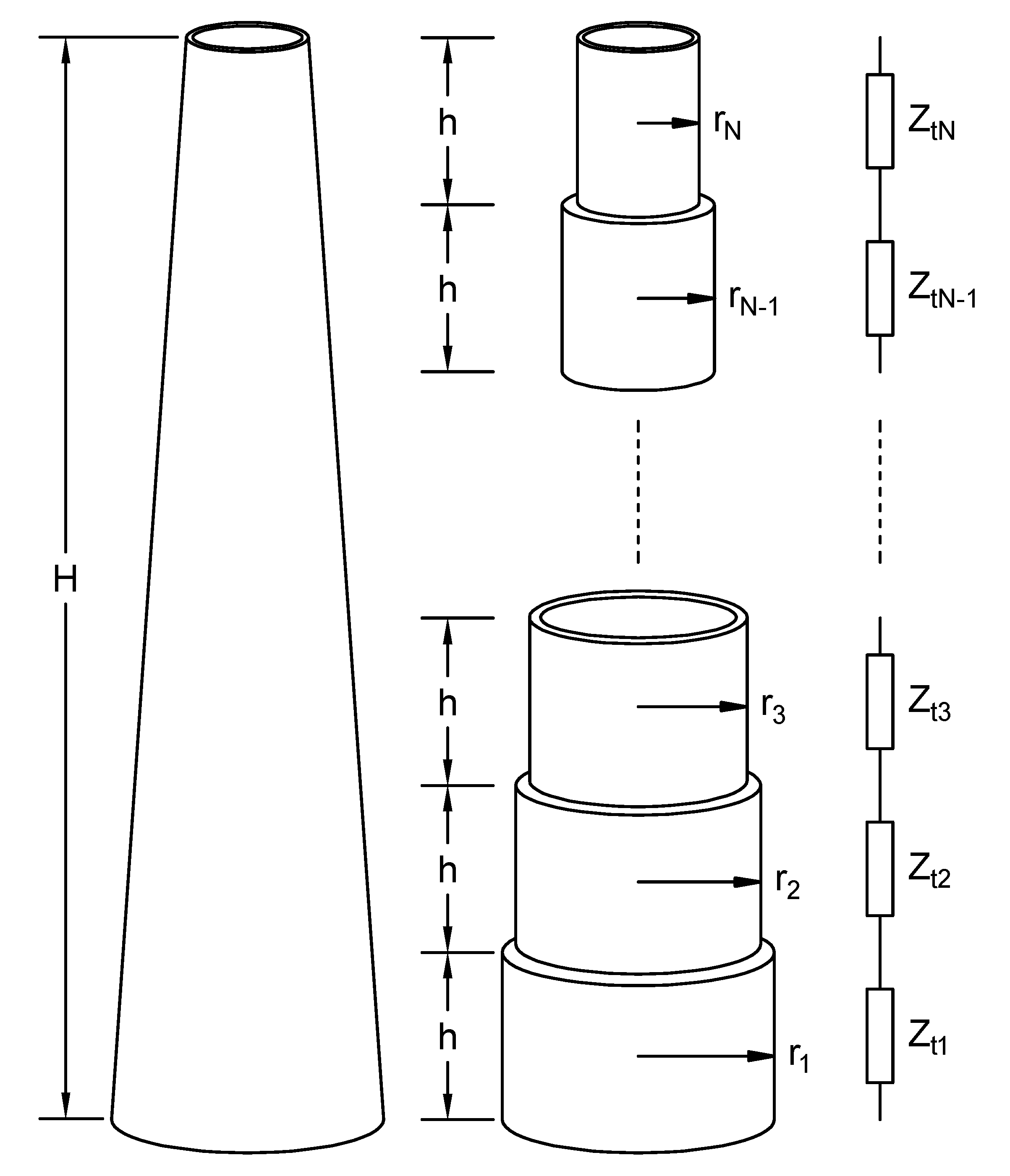
The wind turbine tower is a tall and hollow truncated cone composed of steel. The model of the WT tower is often reappropriated, and even misappropriated, from the high-voltage transmission line (TL) tower models [24]. Since the WT tower is considerably taller than a TL tower, it should not be represented by a simple single-impedance model, but needs a multi-story type of model. The tower needs to be divided into several segments to accurately represent the high-frequency lightning propagation effects. Figure 2 graphically depicts the WT tower model, developed from several individual segments.
As a rule of thumb, the maximum tower segment length should not be longer than [5]:
l s e g , m a x = 1 10 · c f m a x ,
where c is the velocity of light in free space and f m a x is the maximum frequency that has to be represented. Consequently, the tower is divided into a finite number of segments of equal length, such that each segment’s length is shorter than the l s e g , m a x . Surge impedance of the ith tower segment ( i = 1 , 2 , , N ), where N is the number of segments, is calculated using the multi-conductor tower model [30]:
Z t i = 60 · ln 2 2 h r t i 2 ,
where h is tower segment’s height and r t i is the ith radius of the tower segment. The capacitance-to-earth of each tower segment (i.e., parasitic capacitance) is calculated using the formula for the vertical cylindrical conductor above a plane [28]:
C t i = 2 π ϵ 0 h ln 2 h d t i 4 s i + h 4 s i + 3 h ,
where d t i is the tower segment diameter and s i is the height of the segment’s lowest point above the plane. Medium-voltage cables are distanced approximately 0.1 m from the tower’s inner wall at each tower segment, except at the uppermost segment i = N , where the cables pass through the tower center. To calculate capacitance between the tower and the cable screen, each individual tower segment is additionally represented as a truncated cone with an equivalent radius [23]:
r e q i = r 1 i h 2 i + r 2 i h + r 3 i h 1 i 2 h ,
where r 1 i , r 2 i , r 3 i are the radii of the ith tower segment upper, middle, and bottom part, respectively; h 1 i and h 2 i are the heights of the ith tower segment upper-to-middle and middle-to-lower part, respectively. As the tower radius is much larger than the cable’s outer radius, distributed capacitances between the jth ( j = 1 , 2 , , N 1 ) tower segment and the cable screen can be calculated by flattening the tower (i.e., the tower can be assumed as a vertical plane) [17]:
C t s j = 2 π ϵ 0 cosh 1 r e q j 2 + r c 2 + D t s 2 2 r e q j r c ,
where r c is the cable outer radius and D t s is the cable distance from the tower inner wall. The exception is the uppermost (i.e., Nth) tower section, where cables pass through the tower center; thus, a well-known formula for the capacitance of the cylindrical capacitor is used here:
C t s N = 2 π ϵ 0 ln r e q N r c ,
where r e q N is the equivalent radius of the tower’s uppermost segment. WT tower geometry details can be obtained from the manufacturer’s design drawings.

2.6. Medium-Voltage Cables

Medium-voltage (MV) cables connect the transformer located in the nacelle with the MV switchgear at the tower base. The transient response of the vertically-positioned cables has not yet been studied using the frequency-dependent (i.e., full-wave) EM models, to the best of our knowledge. All known transient EM models of the cables (either single-core or three-core) presuppose that they are in the horizontal position relative to the earth’s surface, either buried, installed in a pipe, or in the air. Hence, individual vertical cables are here modeled (Figure 1) as they have been previously by other authors (i.e., representing the core and screen as series R–L branches divided into Nsections) [10,14,17,23].
The cable core and screen DC resistance were taken from the manufacturer’s data. The cable core and the screen inductance are calculated using the assumption that the mutual inductance between the cable core and screen can be neglected [17]. Therefore, the self-inductance equation for a straight wire is used [31]:
L = 2 l · ln l + l 2 + r 2 r l 2 + r 2 + l 4 + r ,
where l is the wire length in cm, r is the wire diameter in cm, and L is the wire inductance in nH. For a very high frequencies, the current is practically flowing on the wire surface due to the skin effect, and there is no magnetic field inside the wire, so Equation (11), with approximation for l > > r , becomes:
L = 2 · l ln 2 l r 1 .
Equation (12) is used for the cable core and screen self-inductance calculation. The current flows through the outer surface of the core where the screen is approximated as a very thin tube; hence, the self-inductance equations for the cable core and the screen segments, respectively, become:
L c = 2 H N ln 2 H r c 1 ,
L s = 2 H N ln 4 H D i 1 ,
where r c is the cable core radius and D i is the diameter across the insulation.
The capacitance between the cable core and the screen depends on the cable geometry and main insulation [10]:
C 23 = 0.02413 · ϵ r , i log D i d + 2 d s e m ,
where ϵ r , i is the insulation layer permittivity and d s e m is the width of the semi-conductive layer.

2.7. Grounding System

The wind turbine grounding transient overvoltage response is determined by the response-time and current-dependence effects of the associated surge impedance of the overall grounding system, which features both concentrated and distributed component parts. The reinforced concrete foundation of the WT serves as a large-volume concentrated grounding system, while an outer ring (outside the concrete foundations), as well as additional horizontally buried grounding conductors (radially emanating from the tower base) along the WT plateau, serve as an extended grounding system. Hence, the high-frequency model of the WT grounding system combines and interconnects a single concentrated (volumetric) component with several distributed-parameter (buried) transmission line components.
The concentrated reinforced concrete foundation is represented as a hemisphere, thus allowing the use of the simplified formula [32]:
R c = 0.2 ρ V 3 ,
where V is the hemisphere volume and ρ is the soil resistivity in the immediate proximity of the concrete foundations.
The outer grounding ring is represented as an octagon (further subdivided into segments as necessary). The horizontally-buried grounding conductors (connected to it) are subdivided into a number of segments (Figure 1), ensuring that the maximum segment length is no longer than [33]:
l m a x = 3160 6 ρ c f m a x ,
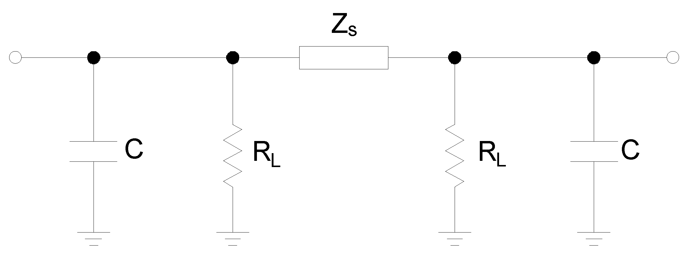
where ρ c is the equivalent soil resistivity around the buried conductors. This subdivision ensures that the grounding conductor’s model, which is based on the cascaded Π –circuits, will be applicable up to a frequency of f m a x from the lightning strike [34]. A single Π –circuit of the grounding conductor’s segment is presented in Figure 3. Each grounding conductor is a cascaded section of these Π –circuits.
The surge impedance, capacitance, and leakage resistance of the equivalent Π –circuit, for a single segment, are calculated using the following equations [33,35,36]:
Z s = ϵ 0 ϵ r μ 0 μ r C ,
C = 4 π ϵ 0 ϵ r l I s e l f + I m u t ,
R L = ρ c 4 π l 2 ( I s e l f + I m u t ) ,
with I s e l f and I m u t representing the appropriate integral expressions with following analytical solutions:
I s e l f = 2 · l · ln l 2 + r 2 + l r l 2 + r 2 + r ,
I m u t = 2 · l · ln l 2 + 4 h c 2 + l 2 h c l 2 + 4 h c 2 + 2 h c ,
where h c is burial depth and l < l m a x is the segment’s length. Additional details regarding the expressions (21) and (22) can be found in [35,36].

2.8. Metal-Oxide Surge Arrester

A typical high-frequency IEEE model of the MV metal-oxide surge arrester is employed, which has already been extensively tested [37]. It features a realistic response to the fast-front (lightning) surges of different wave shapes, i.e., the protection level of the arrester increases slightly from the nominal level with increasing steepness of the impinging surge.
During a lightning strike, the arrester absorbs a certain amount of energy, depending on the lightning current wave shape, duration, and amplitude. The absorbed energy can be expressed as:
W a = t 0 t 1 v s p d · i s p d · d t ,
where t 0 is the time at which the lightning surge appears on the arrester terminals, t 1 is the end time when the arrester no longer conducts lightning current, and v s p d and i s p d are the voltage across the terminals and the current that passes through the arrester, respectively.

3. New-Generation WT Lightning Surge Transient Analysis

3.1. WT Design Details and Input Data

A Nordex Delta4000 series wind turbine with a nominal power of 4.5 MW was analyzed. It is characterized by a tower hub height of 105 m and a rotor diameter of 149 m (with a blade length of approx. 72 m). Moving contacts and bearings are modeled using information from Napolitano et al. [20]. A 5000 kVA, 0.66/33 kV dry-type transformer was analyzed. According to IEC 60071-1:2019, equipment with the highest voltage of U m = 36 kV has standard-rated lightning impulse withstand voltages (LIWL) equal to 145 kV or 170 kV; the latter value was used in the simulations [38]. The coordination level for this LIWL was set to 150 kV in accordance with the IEC 60071-2:2019. Due to the lack of the transformer manufacturer data, equivalent capacitance was estimated at C T r = 0.5 nF, which is in accordance with those of transformers with a similar nominal power range, see, e.g., [29,39].
The transformer in a nacelle is connected to the MV switchgear cubicle placed in the tower base via the MV cables. Single-core N2XS(F)2Y-type MV cables are used in this analysis; however, similar circumstances can be expected with the three-core cables with split-earth conductors (screens). The single-core cables have a 70 mm 2 phase conductor and a screen with a 16 mm 2 cross-section, both made of copper, with cross-linked polyethylene insulation. Basic manufacturer data for the cable are listed in Table 1. The cable screens can be grounded either on both ends via grounding busbars in the nacelle (top end) and the tower bottom (bottom end), or on the single end only. The latter alternative does not provide an optional path for the lightning current flow to the ground. We assume here that the MV cable screens are grounded at both ends (unless stated otherwise).
A EUROMOLD 800SA-10-36N elbow-type metal-oxide surge arrester was selected for step-up transformer protection. When the surge arrester is distanced from the transformer (i.e., not directly placed at the transformer terminals), a 25 mm 2 straight wire with a circular cross-section is used as a connection lead; the wire inductance is calculated using Equation (12). The arrester energy absorption capability is 1.27 kJ/kV of the maximum continuous operating voltage ( U c = 28.8 kV).
The WT grounding system (Figure 1) consists of a single concentrated component (i.e., concrete foundations) with a resistance of R g = 7 Ω , initially calculated for the 500 Ω m equivalent soil resistivity in close vicinity of the concrete foundations, and several distributed components, consisting of the outer earthing ring (approximated as an octagon) and four horizontally-buried grounding conductors along the plateau, with an equivalent soil resistivity of ρ c = 1000 Ω m. Each grounding conductor is subdivided into 7 m long sections, and each section is modeled with a Π circuit (Section 2.7).

3.2. Lightning Current Parameters

The lightning exposure of the new-generation WTs needs to consider for both downward (first and subsequent) as well as upward, lightning strikes. It needs to consider the statistical probability (conditional where appropriate) of these lightning currents. If Eriksson’s expression for the probability of upward lightning strikes as a function of the free-standing object’s height can be evoked [40]: P u p = 52.8 · ln ( H W T ) 230 ( % ) , where H W T is the overall WT height (tower plus blade), then, as a rule of thumb, for this 177 m tall WT, we can expect (on average) that upward-initiated lightning strikes would amount to 43.3% of all incident lightning.
Different parameters that define the lightning current wave shape (front duration, steepness, amplitude, and wave-tail half-time point) in relation to the CIGRE-type current source (Section 2.1) are all taken from the appropriate statistical probability distributions [41]. These parameters individually follow the log-normal (log-N) distribution. Besides, a correlation exists between steepness and amplitude as statistical variables, which necessitates introducing a conditional probability [41].
A probability that a particular lightning current parameter (e.g., amplitude) will exceed a certain value ( I k ) can be determined from the complementary cumulative distribution function (CCDF) of the Log-N distribution:
P ( I I k ) = 0.5 · erfc ln ( I k ) ln ( I μ ) 2 · σ ln I ,
where I μ = 31.1 and σ ln I = 0.48 are the median value and a standard deviation of the associated distribution, respectively; and erfc represents a complementary error function.
When a statistical correlation exists between the lightning-current parameters, the conditional probability is used (e.g., CCDF probability of exceeding amplitude I k with a front-time duration of t f ), as follows [41]:
P ( I I k | t = t f ) = 0.5 · e r f c ln ( I k ) b 2 · σ ,
with
b = ln ( I μ ) + ρ c · σ ln I σ ln t · ( ln ( t f ) ln ( t f μ ) ) ,
σ = σ ln I · 1 ρ c ,
where t f μ = 3.83 and σ l n t = 0.55 represent a median value and a standard deviation of the associated Log-N probability for the lightning-current wave-front duration, respectively; ρ c = 0.47 is the correlation coefficient between these random variables. Statistical parameters of the first and subsequent downward (negative) as well as upward lightning currents were obtained from the IEEE WG [41].
Hence, the following lightning currents are considered in the subsequent EMTP-RV numerical simulations:
  • Downward lightning (first and subsequent): 60 kA and 4/75 µs (first), immediately followed by 20 kA and 1/75 µs (subsequent) strike;
  • Upward lightning (fast-front): 12 kA and 1/75 µs;
  • Upward lightning (slow-front): 12 kA and 8/75 µs.
These parameters were selected to represent the influence of different amplitude and front-time pairs. Wave-tail time is fixed in all cases on the median probability value. We show that very dangerous overvoltages are generated from these events of moderate probability. Even more serious consequences could be expected from the lower-probability events, which would have to be considered as part of a WT insulation coordination study [38].

3.3. Analysis of EMTP-RV Numerical Simulations

The presented WT model, once assembled in the EMTP-RV, affords flexibility and considerable detail in studying the overvoltage stresses of WT electrical systems. Due to space limitations, only a select portion of the obtained numerical results are presented here, with a focus on the step-up transformer inside a nacelle, which will provide necessary information for the subsequent recommendations concerning the optimal WT overvoltage protection design. Special consideration is given to the influence of the surge arrester (i.e., SPD) location on overvoltage suppression and mitigation.
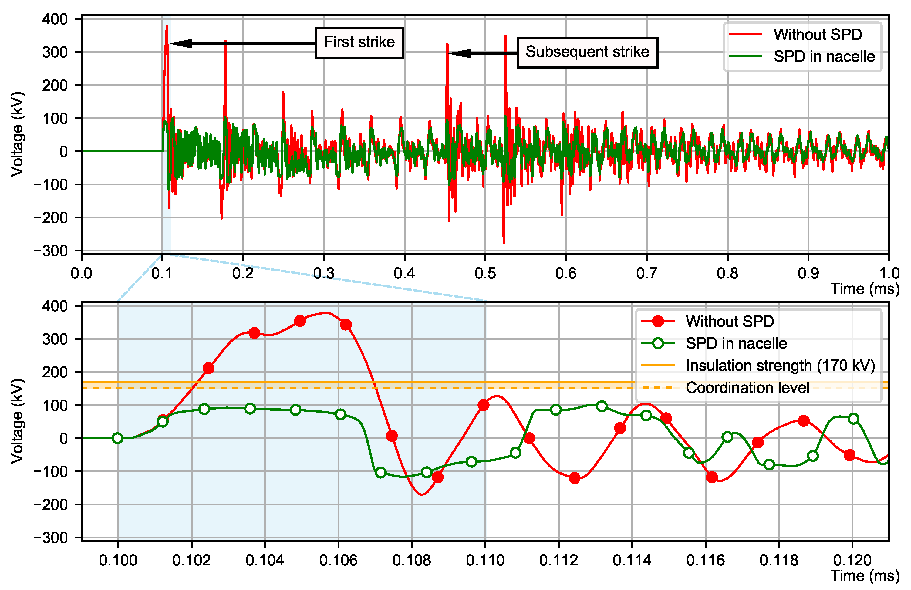
Figure 4 presents the overvoltage wave shapes at the transformer terminal due to the downward lightning strike (first and subsequent). It considers the transformer with and without the SPD installation inside a nacelle. The SPD inside a nacelle at the transformer terminals can suppress this overvoltage below its insulation (coordination) withstand level.
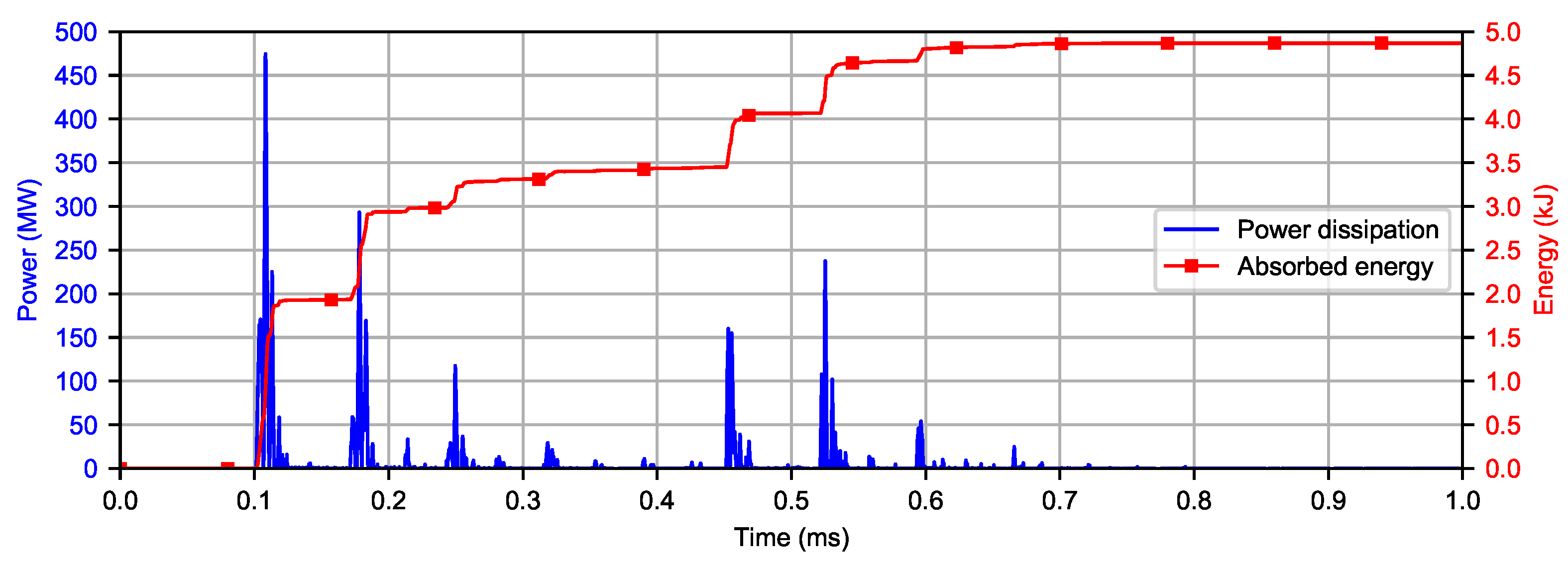
Figure 5 presents the power and energy absorption of this surge arrester for the treated lightning strike. During the downward strike (first and subsequent), the surge arrester absorbed less than 5 kJ, which is considerably below its energy absorption capability. However, higher energy absorption is expected from the switching overvoltages; hence, this calculation alone cannot be used for establishing the needed absorption capacity of the SPD.
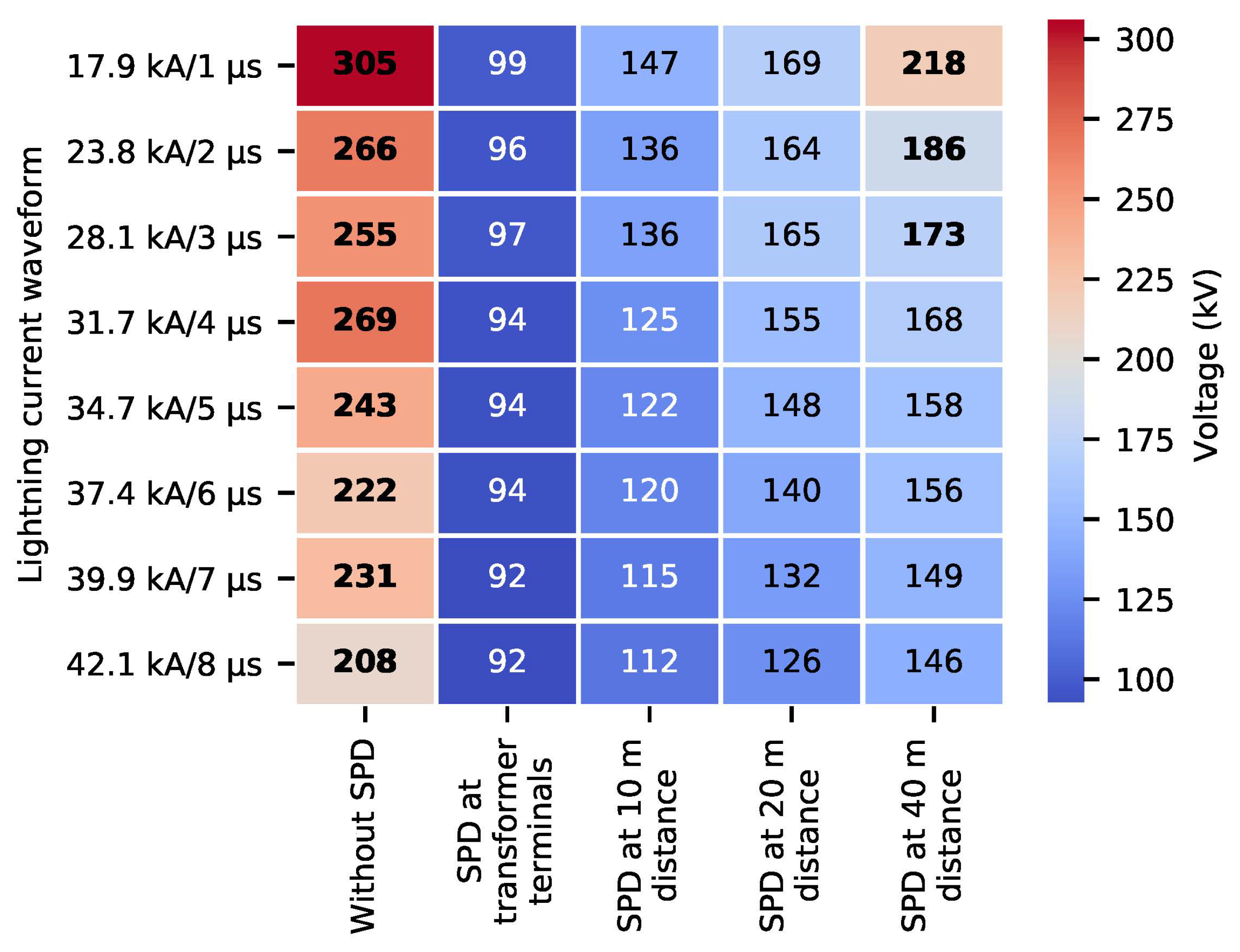
The distance between the SPD and the transformer terminals, as well as the steepness of the impinging surge, influences the SPD protection zone and its ability to suppress overvoltages at the transformer terminals. Hence, the effects of different SPD leads lengths and wave-front times of the impinging surge were examined. Wave front time is varied between 1 and 8 µs, while the amplitude is selected using (25), with a median (conditional) probability, which means that these amplitudes will be exceeded with a 50% probability. Based on this, Figure 6 presents amplitudes (i.e., peak values) of the obtained overvoltages for different lightning currents and arrester leads lengths. The presence of the SPD is therefore seen as absolutely indispensable to the overvoltage protection of the step-up transformer. The SPD clearly needs to be installed as close as possible to the transformer terminals (the total length of the arrester leads should be minimized, i.e., 10–20 m).
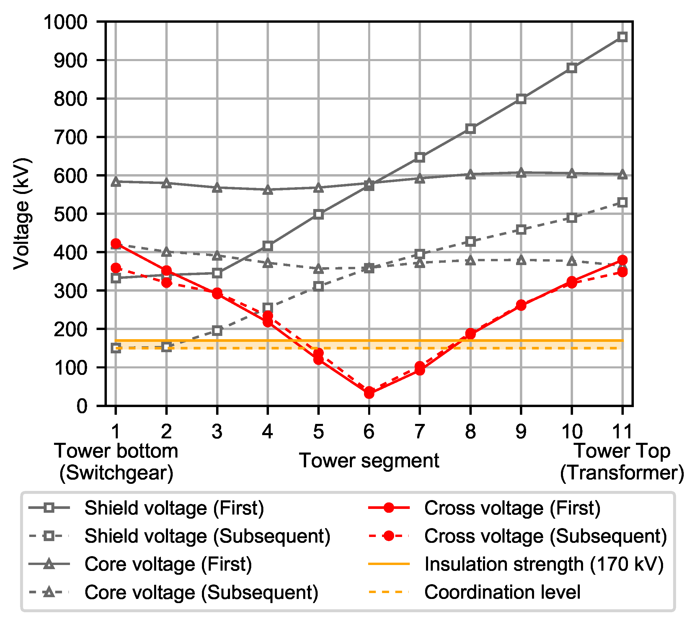
In addition to the step-up transformer (inside a nacelle), MV cables inside a tower are exposed to considerable overvoltage stresses. To examine these, Figure 7 presents he overvoltage distribution along the MV cable length due to downward lightning strikes (first and subsequent). Only peak values along the cable length (from the bottom to the top of the tower) of the core, screen, and cross voltages are presented, without the SPD installation. The cross overvoltage exhibits a typical V shape [14], and it exceeds the cable insulation strength (cable LIWL is assumed equal to that of the transformer) for a considerable length of the cable.
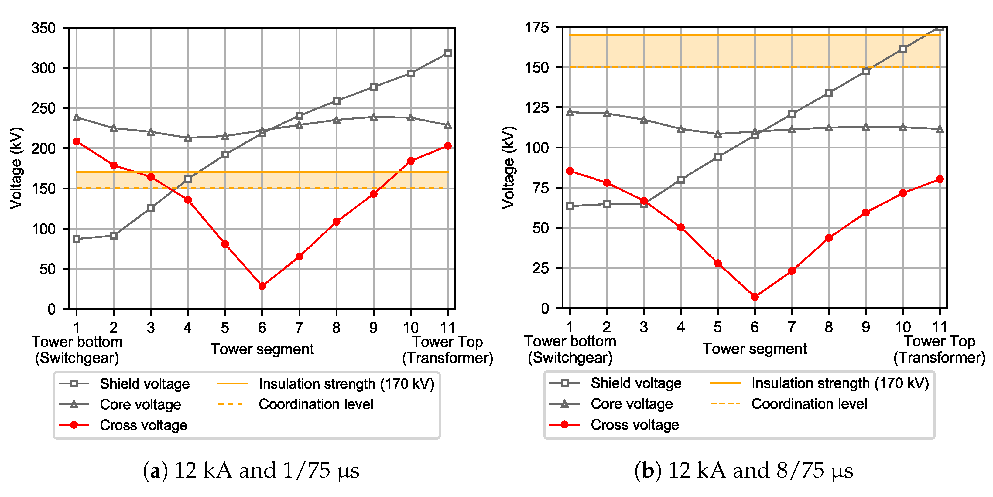
Figure 8 presents the same kind of overvoltage distribution along the MV cable length, but due to the upward lightning strike with (Figure 8a) 12 kA and 1/75 µs and (Figure 8b) 12 kA and 8/75 µs (again without the SPD installation). The cross voltage exceeds the cable insulation strength in case (a), although somewhat less dramatically. Only in case of a very long wave-front time duration, the overvoltages do not exceed the insulation level of the cables (case b). Comparing the cross voltages along the cable due to the aforementioned lightning strikes with equal amplitudes, we conclude that the lightning surge steepness is of utmost importance. Notably, the cable screen is grounded at both ends in all above-treated cases.
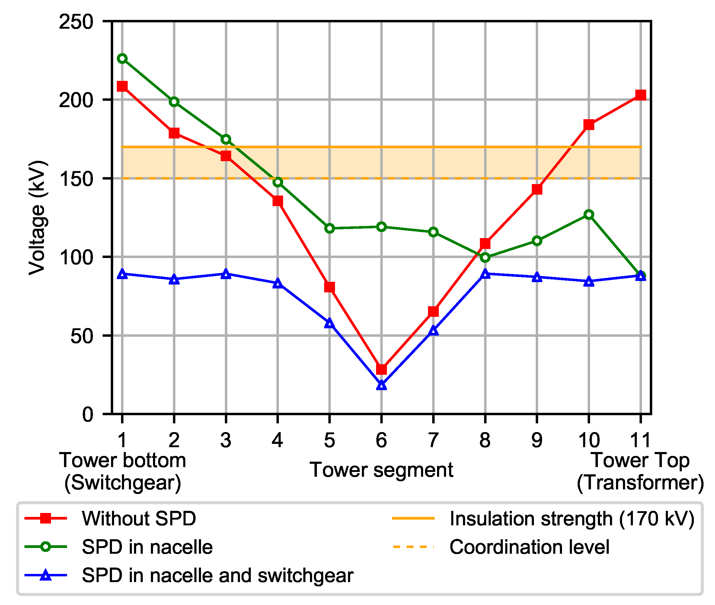
The results clearly show that the step-up transformer inside a nacelle is exposed to considerable lightning stresses, both from upward and downward lightning strikes, and needs to be protected with SPDs. However, with only a single set of SPDs (in three phases) installed at the terminals of the step-up transformer (Figure 4), it is not possible to provide overvoltage protection to the cable end in the switchgear cubicle at the base of the WT tower. To demonstrate this, Figure 9 presents the overvoltage distribution across the MV cable with 12 kA and 1/75 µs for three different situations of SPD installation. With the SPD at the terminals of the step-up transformer, there is no protection for the cable end at the tower base. The cross voltage even starts increasing from the middle of the cable toward the tower bottom due to the backsurge flow phenomenon [14]. Only by providing a second set of SPDs in the switchgear cubicle at the tower base does it become possible to cover the entire length of the cable with adequate overvoltage protection. This holds only if the cable screens are grounded on both ends.
Consequently, it is important to examine the influence of the cable screen grounding practices (i.e., grounding on a single end or at both ends) on the lightning overvoltage distribution and overvoltage stresses of the step-up transformer inside a nacelle. The optimal grounding treatment of the cable screens must also be established, as seen from the lightning overvoltage mitigation perspective and insulation coordination design. In that regard, Table 2 presents the comprehensive simulation results (peak values of overvoltages) developed along the cable (i.e., cross voltage) for different cable screen grounding practices, i.e., screen grounding in the nacelle (top end), in the tower base (bottom end), or at both ends. Upward lightning strike with 12 kA and 1/75 µs is used again. Different locations of the SPDs installation are considered as well. Note that position y = 0 indicates the cable end at the tower base, i.e., in the switchgear cubicle, and y = H indicates a cable end at the tower top, i.e., at the step-up transformer inside a nacelle.
From the results in Table 2, several important conclusions can be drawn. First, if there is no SPD installed in the WT, extremely dangerous overvoltages are attained regardless of how the cable screens are grounded. The absence of SPDs is an unrealistic situation, but it serves to show that the lowest possible overvoltages occur in the case of grounding cable screens at both ends. Second, if a single set of SPDs is installed in the WT, it cannot cover the full length of the MV cables with its protection zone, regardless of where it is installed (in a nacelle or in a switchgear cubicle). This is due to the considerable length of the MV cables inside a tower. In this case, again, it is best to ground cable screens at both ends, since this results in the lowest possible overvoltage. With the cable screens grounded on a single end, the other ungrounded end is stressed with extremely high overvoltages. With screens grounded on a single end while SPDs are installed on the other end, there is considerable cross voltage increase along the entire cable length. Finally, only two sets of SPDs installed at both MV cable ends, i.e., inside a nacelle and the switchgear cubicle, provide fully-effective overvoltage protection to the WT electrical systems. Again, the lowest overvoltages are obtained for the screens grounded at both ends. Conversely, with screens grounded on a single end, even with two sets of SPDs (at both cable ends), the overvoltage in the middle of the cable length exceeds its insulation strength (LIWL). This is an important finding.

4. Recommendations for Optimal WT Overvoltage Protection

From the presented numerical simulations and subsequent comprehensive analysis (Section 3.3), the following main conclusions can be drawn:
  • Steepness of the impinging surge is the single most important factor influencing the overvoltage stresses of the step-up transformer inside a nacelle due to the capacitive coupling, which predominates during the front of the surge.
  • The step-up transformer in a nacelle is exposed to considerable lightning overvoltage stresses, which is evident from the amplitudes associated with a median (conditional) probability producing overvoltages that exceed its insulation level (LIWL).
  • The cross voltage of the MV single-core cable exhibits a typical V shape [23] and exceeds its insulation level at both ends, even for moderate-probability lightning currents of both upward and downward strikes.
  • Lowering the WT grounding system impulse impedance does not considerably influence the cross voltage of the MV single-core cables, nor does it influence the overvoltage stresses of the step-up transformer in the nacelle, which agrees with the previous findings [14,23].
  • The protection zone of the MO surge arrester, which is a function of the difference between the overvoltage amplitude and the protection level of the arrester as well as of the steepness of the impinging surge, is around 10 meters for a median (conditional) probability lightning currents; the zone shrinks rapidly with increasing steepness of the impinging surge.
  • Unless the cable screens are grounded at both ends, dangerous overvoltages form on the open-ended side, which cannot be lowered even by installing surge arresters at both cable ends.
Unequivocally, the MV surge arrester installed in the switchgear cubicle (tower base) cannot provide adequate overvoltage protection to the step-up transformer in a nacelle when the tower is taller than 100 m. Its presence in the base of the tower may even increase the overvoltage at the step-up transformer terminals during lightning strikes. This was corroborated by Yang et al. [23]. These findings negate the IEC 61400-24:2019 statement that the designer has to decide “if for instance arresters at the bottom of the tower can provide the needed protection for a transformer placed in the nacelle”, calling for an amendment to and partial revision of the IEC 61400-24:2019 concerning these issues. We are under the impression that this standard does not place due importance on the overvoltage issues associated with the placement of the transformer in a nacelle (e.g., no distinction is made between the transformer placed in the nacelle and the tower base as far as its overvoltage protection is concerned). Furthermore, the standard solely recognizes that transient EM simulations should be used to asses the levels of transients from medium- or high-voltage cables outside the wind turbine (which are, in our opinion, inferior), ignoring (or at least overshadowing) the potential hazardous overvoltages on the transformers in the nacelle during direct lightning strikes [4].
Considering these conclusions, in addition to what has already been stated, we put forward the following recommendations for the effective overvoltage protection of the step-up transformer inside a nacelle:
(a)
The dry-type step-up transformer inside a nacelle should be selected with the highest possible insulation level (in relation to lightning surges, LIWL), considering the nominal voltage levels of its windings, following IEC 60071-1:2019 [38].
(b)
If only a single set of MV surge arresters is applied to the WT overvoltage protection, it should be installed at the terminals of the step-up transformer inside a nacelle and grounded, with as short a connection as possible, to the same point to which the screens of the MV cables are grounded (e.g., grounding busbar inside a nacelle); it is preferable to use an elbow-type surge arrester. Connecting leads (i.e., earth connection) should be minimal and should be preferably achieved with a flat conductor.
(c)
The MV surge arrester at the terminals of the step-up transformer inside a nacelle should be no less than Line Discharge Class 2 level considering the importance of the step-up transformer, vicinity to the generator and exposure of the WT to frequent direct lightning strikes, in accordance with IEC 60099-4:2014 [42].
(d)
A single set of MV surge arresters installed at the step-up transformer terminals inside a nacelle cannot provide efficient (lightning) surge protection to the MV cable heads (core ends) at the base of the WT tower; the second set of MV surge arresters should then be installed at the switchgear cubicle in the base of the WT tower to provide a fully-effective (lightning) surge protection to this end of the cable.
(e)
The second set of MV surge arresters at the base of the WT tower should preferably be of the elbow-type design and could be Line Discharge Class 1 level, in accordance with IEC 60099-4:2014 [42], since they will be aided, in terms of the energy absorption capacity, by the MO surge arresters in the nacelle.
(f)
Screens of the MV single-core cables should be grounded at both ends; this may reduce their current-carrying capacity [43], but will result in lower overvoltage stresses at the step-up transformer terminals (inside a nacelle). Tt will also remove the need for installing surge protection for the cable jacket.
(g)
If the single-core cable screens are to be grounded on a single end, which is a decidedly inferior option that is not recommended, that end should be on the side of the step-up transformer inside a nacelle; in that case, another set of low-voltage SPDs should be installed at the ungrounded end of the cable screens as a protection for the cable jacket.
Finally, the lightning-related risk is not the same for all WTs within onshore wind farms. The risk is influenced by the wind farm topology, terrain orography, keraunic level, soil resistivity, wind farm layout in relation to the prevailing wind direction, local weather patterns (i.e., winter lightning), and other influential factors [44]. A lightning risk analysis for the entire wind farm ought to establish the necessary conditions for installing the second set of arresters for each individual WT, considering the total price of the risk and its premium level. The price of the risk needs to account for the financial losses arising from lightning-related damage, replacement costs, and lost revenue from downtime [44]. After all, the investment in surge arresters is seen as buying insurance!

5. Conclusions

This paper presented a comprehensive analysis of lightning overvoltage stresses of the step-up transformer inside a nacelle for the most-recently designed multi-megawatt wind turbines. Both upward and downward lightning (first and subsequent) strikes were considered. This is the first time, to the best of our knowledge, that this type of analysis has been provided for new-generation onshore WTs with a step-up transformer installed inside a nacelle. Analysis was performed on the basis of a large body of exhaustive numerical simulations, produced by employing a WT model for fast-front transients, assembled in the EMTP-RV software package. We provided a thorough analysis of overvoltage distributions along the MV cables installed vertically inside WT towers, including the influence of the backsurge phenomenon and its mitigation. This analysis fully considered the important influence of the cable screen grounding practice on the resulting overvoltage stresses.
We described important conclusions regarding the lightning overvoltage propagation through the MV electrical systems of the new-generation WTs, with a special emphasis on the stresses of the cable insulation (cable heads, screen grounding practice) and of the step-up transformer inside a nacelle. Some of our findings, particularly regarding SPD installation location, highlight the shortcomings of IEC 61400-24:2019, calling for its amendment and/or revision of parts pertaining to these issues. We also encourage extending the current IEC standard with a more specific set of guidelines regarding the overvoltage protection of the step-up transformers placed inside the nacelle, which are close to non-existent at present.
We offered recommendations for the (optimal) overvoltage protection of new-generation wind turbines with step-up transformers in a nacelle, including preferable screen grounding practice, and installation location of the MO surge arresters at the medium-voltage level. They can, tentatively, serve as basic guidelines for WT insulation coordination studies pertaining to the lightning overvoltage stresses. However, the analysis did not extend beyond a single wind turbine to consider the rest of the wind park network. A future study should consider the wind farm topology in relation to the risk(s) associated with direct WT lightning strikes.
The proposed model, for obvious reasons, included certain assumptions and simplifications, which could be removed by introducing (proprietary) information regarding the design of the step-up transformer, MV cables, and other details of the internal WT components and systems. Manufacturers and/or wind turbine owners ought to be able to share the data and information pertinent to these crucial components (e.g., frequency-response measurements needed for a wide-band transformer model) without revealing their trade secrets and proprietary design details. It would benefit the engineers in designing the overvoltage protection, which would translate into increased security and reliability of the WT and wind park, ensuring its optimal performance with minimum downtime.

Author Contributions

Conceptualization, P.S., A.M. and R.G.; Investigation, A.M.; Methodology, P.S. and A.M.; Resources, A.M. and R.G.; Software, A.M.; Supervision, R.G.; Validation, P.S. and R.G.; Visualization, A.M.; Writing—original draft, P.S. and A.M.; Writing—review and editing, R.G. All authors have read and agreed to the published version of the manuscript.

Funding

This research received no external funding.

Conflicts of Interest

The authors declare no conflict of interest.

Abbreviations

The following abbreviations are used in this manuscript:
CCDFComplementary cumulative distribution function
CIGREConseil International des Grands Réseaux Électriques
EMElectromagnetic
EMTPElectroMagnetics Transients Program
IEEEInstitute of Electrical and Electronics Engineers
LIWLLightning insulation withstand level
LPSLightning protection system
MOMetal-oxide
MVMedium voltage
SPDSurge protection device (i.e., surge arrester)
TLTransmission line
WTWind turbine

References

  1. Rodriguez-Hernandez, O.; Martinez, M.; Lopez-Villalobos, C.; Garcia, H.; Campos-Amezcua, R. Techno-Economic Feasibility Study of Small Wind Turbines in the Valley of Mexico Metropolitan Area. Energies 2019, 12, 890. [Google Scholar] [CrossRef] [Green Version]
  2. Micallef, D.; van Bussel, G. A Review of Urban Wind Energy Research: Aerodynamics and Other Challenges. Energies 2018, 11, 2204. [Google Scholar] [CrossRef] [Green Version]
  3. Gough, M.; Lifti, M.; Castro, R.; Madhlopa, A.; Khan, A.; P.S. Catalao, J. Urban Wind Resource Assessment: A Case Study on Cape Town. Energies 2019, 12, 1479. [Google Scholar] [CrossRef] [Green Version]
  4. IEC 61400-24:2019, Wind Energy Generation Systems—Part 24: Lightning Protection; International Standard, International Electrotechnical Commission: Geneva, Switzerland, 2019.
  5. Zhang, X.; Zhang, Y.; Liu, C. A complete model of wind turbines for lightning transient analysis. J. Renew. Sustain. Energy 2014, 6, 013113. [Google Scholar] [CrossRef]
  6. Zhang, L.; Lao, H.; Wang, G.; Zou, L.; Zhao, T.; Fang, Z. A new method for spatial allocation of turbines in a wind farm based on lightning protection efficiency. Wind Energy 2019, 22, 1310–1323. [Google Scholar] [CrossRef]
  7. Zalhaf, A.S.; Abdel-Salam, M.; Mansour, D.A.; Ookawara, S.; Ahmed, M. Assessment of wind turbine transient overvoltages when struck by lightning: Experimental and analytical study. IET Renew. Power Gener. 2019, 13, 1360–1368. [Google Scholar] [CrossRef]
  8. Tao, S.; Zhang, X.; Wang, Y.; Yang, J. Transient Behavior Analysis of Offshore Wind Turbines during Lightning Strike to Multi-Blade. IEEE Access 2018, 6, 22070–22083. [Google Scholar] [CrossRef]
  9. Tao, S.; Yao, X.; Liu, B.; Zhang, X.; Wang, Y. Research of lightning transient potential on the jacket foundation offshore wind turbines. E3S Web Conf. 2019, 95, 6–10. [Google Scholar] [CrossRef]
  10. Shariatinasab, R.; Kermani, B.; Gholinezhad, J. Transient modeling of the wind farms in order to analysis the lightning related overvoltages. Renew. Energy 2019, 132, 1151–1166. [Google Scholar] [CrossRef]
  11. Alipio, R.; Conceiçāo, D.; Conti, A.D.; Yamamoto, K.; Dias, R.N.; Visacro, S. A comprehensive analysis of the effect of frequency-dependent soil electrical parameters on the lightning response of wind-turbine grounding systems. Electr. Power Syst. Res. 2019, 175, 105927. [Google Scholar] [CrossRef]
  12. Deshagoni, R.G.; Auditore, T.; Rayudu, R.; Moore, C.P. Factors Determining the Effectiveness of a Wind Turbine Generator Lightning Protection System. IEEE Trans. Ind. Appl. 2019, 55, 6585–6592. [Google Scholar] [CrossRef]
  13. Chen, H. A Study on the Cable Grounding Condition in Wind Turbines Under Direct Lightning. In Proceedings of the 2019 11th Asia-Pacific International Conference on Lightning (APL), Hong Kong, China, 12–14 June 2019; pp. 1–6. [Google Scholar]
  14. Jiang, J.L.; Chang, H.C.; Kuo, C.C.; Huang, C.K. Transient overvoltage phenomena on the control system of wind turbines due to lightning strike. Renew. Energy 2013, 57, 181–189. [Google Scholar] [CrossRef]
  15. Malcolm, N.; Aggarwal, R. The impact of multiple lightning strokes on the energy absorbed by MOV surge arresters in wind farms during direct lightning strikes. Renew. Energy 2015, 83, 1305–1314. [Google Scholar] [CrossRef]
  16. Sarajčev, P.; Goić, R. A Review of Current Issues in State-of-Art of Wind Farm Overvoltage Protection. Energies 2011, 4, 644–668. [Google Scholar] [CrossRef] [Green Version]
  17. Jiang, J.L.; Chang, H.C.; Kuo, C.C. Analysis of transient energy affection for wind farm under lightning. Energy 2012, 48, 292–297. [Google Scholar] [CrossRef]
  18. Sekioka, S.; Otoguro, H.; Funabashi, T. A Study on Overvoltages in Windfarm Caused by Direct Lightning Stroke. IEEE Trans. Power Deliv. 2019, 34, 671–679. [Google Scholar] [CrossRef]
  19. Diendorfer, G. On the risk of upward lightning initiated from wind turbines. In Proceedings of the 2015 IEEE 15th International Conference on Environment and Electrical Engineering (EEEIC), Rome, Italy, 10–13 June 2015; pp. 872–876. [Google Scholar]
  20. Napolitano, F.; Paolone, M.; Borghetti, A.; Nucci, C.A.; Cristofolini, A.; Mazzetti, C.; Fiamingo, F.; Marzinotto, M. Models of wind-turbine main-shaft bearings for the development of specific lightning protection systems. IEEE Trans. Electromagn. Compat. 2011, 53, 99–107. [Google Scholar] [CrossRef]
  21. Badrzadeh, B.; Hogdahl, M.; Isabegovic, E. Transients in Wind Power Plants—Part I: Modeling Methodology and Validation. IEEE Trans. Ind. Appl. 2012, 48, 794–807. [Google Scholar] [CrossRef]
  22. EMTP-RV. ElectroMagnetic Transients Program—Restructured Version. Available online: https://www.emtp-software.com/ (accessed on 7 January 2021).
  23. Yang, Q.; Tao, J.; He, Y.; Zhang, B. Analysis and suppression measures of lightning transient overvoltage in the signal cable of wind turbines. Wind Energy 2018, 21, 211–225. [Google Scholar] [CrossRef]
  24. Martinez-Velasco, J.A. (Ed.) Power System Transients: Parameter Determination; CRC Press: Boca Raton, FL, USA, 2010. [Google Scholar]
  25. CIGRE Working Group Guidelines for Representation of Network Elements when Calculating Transients. CIGRE Broch. 1988, 39, 1–29.
  26. CIGRE Working Group Guide to procedures for estimating the lightning performance of transmission lines. CIGRE Broch. 1991, 63, 61.
  27. Yan, J.; Wang, G.; Ma, Y.; Guo, Z.; Ren, H.; Zhang, L.; Li, Q.; Yan, J.D. Electrical and thermal performance of different core materials applied in wind turbine blades under lightning strikes. Wind Energy 2019, 22, 1603–1621. [Google Scholar] [CrossRef]
  28. Kuffel, E.; Zaengl, W.S.; Kuffel, J. High Voltage Engineering: Fundamentals, 2nd ed.; Butterworth–Heinemann: Oxford, UK, 2000. [Google Scholar]
  29. Greenwood, A. Electrical Transients in Power Systems, 2nd ed.; John Wiley & Sons, Inc.: New York, NY, USA, 1991. [Google Scholar]
  30. Ametani, A.; Kasai, Y.; Sawada, J.; Mochizuki, A.; Yamada, T. Frequency-dependent impedance of vertical conductors and a multiconductor tower model. IEE Proc. Gener. Transm. Distrib. 1994, 141, 339–345. [Google Scholar] [CrossRef]
  31. Rosa, E.B. The Self and Mutual Inductances of Linear Conductors. Bull. Bur. Stand. 1908, 4, 301–344. [Google Scholar] [CrossRef]
  32. Brandenbursky, V.; Farber, A.; Korj, V.; Braunshtein, A. Ground resistance calculation for small concrete foundations. Electr. Power Syst. Res. 2011, 81, 408–413. [Google Scholar] [CrossRef]
  33. Vujevic, S.; Sarajcev, P. An EMTP Extension for Computing Earthing System Transient Step and Touch Voltages. In Proceedings of the CIGRE Symposium: Transient Phenomena in Large Electric Power Systems, Zagreb, Croatia, 18–21 April 2007; pp. 1–8. [Google Scholar]
  34. Dommel, H.W. EMTP Theory Book, 2nd ed.; Microtran Power System Analysis Corporation: Vancouver, BC, Canada, 1992. [Google Scholar]
  35. Vujevic, S.; Sarajcev, P.; Lucic, R. Computing the mutual impedances between segments of earthing system conductors. In WIT Transactions on Modelling and Simulation; WIT Press: Southampton, UK, 2005; pp. 641–650. [Google Scholar]
  36. Sarajcev, P.; Vujevic, S.; Lovric, D. Time-Harmonic Current Distribution on Conductor Grid in Horizontally Stratified Multilayer Medium. Prog. Electromagn. Res. B 2011, 31, 67–87. [Google Scholar] [CrossRef] [Green Version]
  37. Martinez, J.A.; Durbak, D.W. Parameter determination for modeling systems transients–Part V: Surge arresters. IEEE Trans. Power Deliv. 2005, 20, 2073–2078. [Google Scholar] [CrossRef]
  38. IEC 60071-1:2019, Insulation Co-Ordination—Part 1: Definitions, Principles and Rules; International Standard, International Electrotechnical Commission: Geneva, Switzerland, 2019.
  39. Das, J.C. Surges transferred through transformers. In Proceedings of the Conference Record of the 2002 Annual Pulp and Paper Industry Technical Conference (Cat. No.02CH37352), Toronto, ON, Canada, 17–21 June 2002; pp. 139–147. [Google Scholar]
  40. Eriksson, A.J. The Incidence of Lightning Strikes to Power Lines. IEEE Trans. Power Deliv. 1987, 2, 859–870. [Google Scholar] [CrossRef]
  41. Chowdhuri, P.; Anderson, J.G.; Chisholm, W.A.; Field, T.E.; Ishii, M.; Martinez, J.A.; Marz, M.B.; McDaniel, J.; McDermott, T.E.; Mousa, A.M.; et al. Parameters of Lightning Strokes: A Review. IEEE Trans. Power Deliv. 2005, 20, 346–358. [Google Scholar] [CrossRef]
  42. IEC 60099-4:2014. Surge Arresters–Part 4: Metal-Oxide Surge Arresters without Gaps for a.c. Systems; International Standard, International Electrotechnical Commission: Geneva, Switzerland, 2014.
  43. Schött-Szymczak, A.; Walczak, K. Analysis of Overvoltages Appearing in One-Sidedly Ungrounded MV Power Cable Screen. Energies 2020, 13, 1821. [Google Scholar] [CrossRef] [Green Version]
  44. Sarajcev, P.; Jakus, D.; Mudnic, E. Gaussian process regression modeling of wind turbines lightning incidence with LLS information. Renew. Energy 2020, 146, 1221–1231. [Google Scholar] [CrossRef]
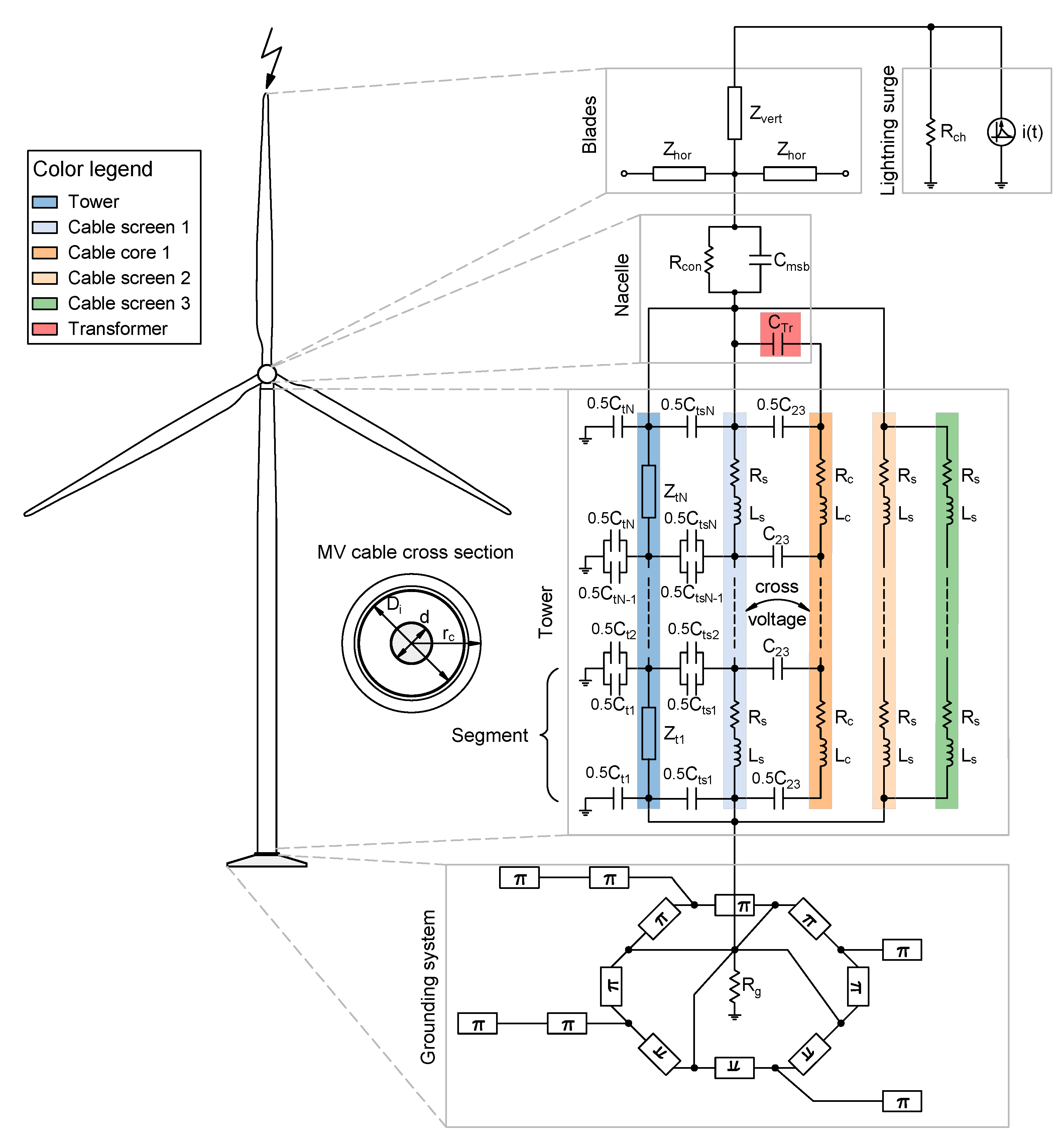
Figure 1. Basic outline of the wind turbine (WT) model for a fast-front transient analysis.
Energies 14 00322 g001
Figure 2. Schematic representation of the multi-story WT tower model.
Energies 14 00322 g002
Figure 3. Equivalent Π –circuit of the horizontally buried conductor’s segment.
Energies 14 00322 g003
Figure 4. Transformer overvoltage(s) with and without surge arrester (SPD) with 60 kA and 4/75 µs (first stroke), and 20 kA and 1/75 µs (subsequent stroke).
Energies 14 00322 g004
Figure 5. Absorbed energy of the SPD inside a nacelle with 60 kA and 4/75 µs (first stroke), and 20 kA and 1/75 µs (subsequent stroke).
Energies 14 00322 g005
Figure 6. Transformer overvoltage amplitudes as a function of the arrester lead length and the steepness of the impinging surge.
Energies 14 00322 g006
Figure 7. Overvoltage distribution across the power cable with downward lightning: 60 kA and 4/75 µs (first stroke), and 20 kA and 1/75 µs (subsequent stroke).
Energies 14 00322 g007
Figure 8. Overvoltage amplitudes distribution across the power cable with upward lightning strikes.
Energies 14 00322 g008
Figure 9. Overvoltage amplitudes distribution across the power cable with 12 kA and 1/75 µs.
Energies 14 00322 g009
Table 1. Basic medium-voltage (MV) cable data.
ParameterUnitValue
Cable nominal voltages U m a x / U n / U 0 (kV)36/30/18
Core and screen cross section(mm 2 )70/16
Conductor diameter(mm)10.3
Insulation thickness(mm)8.0
Sheath thickness(mm)2.5
Cable outer diameter(mm)36.0
Table 2. Cable cross voltages as a function of the screen grounding practice and SPD location.
SPD LocationScreen GroundingCross Voltage (kV)
y = 0 y = 0.3 H y = 0.5 H y = 0.7 H y = H
No SPDBoth ends208.5135.728.4108.5202.9
Top end811.589.5111.9104.2143.4
Bottom end64.144.856.042.5721.5
NacelleBoth ends226.2147.6119.199.687.9
Top end813.067.8110.389.176.8
Bottom end682.7670.1711.5660.3109.2
SwitchgearBoth ends87.892.3122.4134.3207.6
Top end110.4650.8696.4690.4670.6
Bottom end69.454.768.552.4751.6
Nacelle and SwitchgearBoth ends89.383.418.689.488.2
Top end110.3468.8408.3321.5106.4
Bottom end104.1315.5392.9456.6106.1
Publisher’s Note: MDPI stays neutral with regard to jurisdictional claims in published maps and institutional affiliations.