Article

An Anti-Fluctuation Compensator Design and Its Control Strategy for Wind Farm System

Department of Electrical Engineering, National Chin-Yi University of Technology, Taichung 41107, Taiwan
*
Author to whom correspondence should be addressed.
Energies 2021, 14(19), 6413; https://doi.org/10.3390/en14196413
Submission received: 28 August 2021 / Revised: 27 September 2021 / Accepted: 29 September 2021 / Published: 7 October 2021
(This article belongs to the Topic Power System Modeling and Control)

Abstract

:
Large-scale wind farms in commercial operations have demonstrated growing influence on the stability of an electricity network and the power quality thereof. Variations in the output power of large-scale wind farms cause voltage fluctuations in the corresponding electrical networks. To achieve low-voltage ride-through capability in a doubly fed induction generator (DFIG) during a fault event, this study proposes a real-time reactive power control strategy for effective DFIG application and a static synchronous compensator (STATCOM) for reactive power compensation. Mathematic models were developed for the DFIG and STATCOM, followed by the development of an indirect control scheme for the STATCOM based on decoupling dual-loop current control. Moreover, a real-world case study on a commercial wind farm comprising 23 DFIGs was conducted. The voltage regulation performance of the proposed reactive power control scheme against a fault event was also simulated. The simulation results revealed that enhanced fault ride-through capability and prompt recovery of the output voltage provided by a wind turbine generator could be achieved using the DFIG along with the STATCOM in the event of a three-phase short-circuit fault.

Graphical Abstract

1. Introduction

Currently, wind power is considered to be among the most promising renewable energy sources for commercial applications. The commercial application of large-scale wind turbine generators demonstrates the growing need for stability and quality in electrical networks. Because of the inherent characteristics of wind-powered generator sets, an output fluctuation occurs when substantial wind power is supplied to an electrical network. For example, considerable disturbance in a wind farm engenders a three-phase short-circuit fault and causes inadequate supply of reactive power [1,2,3,4]. Wind turbine generators can be disconnected from an electrical network in the event of overspeeding and low output voltage or to ensure protection. When the affected power generator set is disconnected, the output voltage provided by the set is unlikely to be recovered, resulting in a short-term power outage in the entire power station or even the connected electrical network. To avoid this, two effective measures are employed against an unintended power failure. The first measure entails applying a high-speed real-time reactive power compensator, such as a static var compensator (SVC), static synchronous compensator (STATCOM), or thyristor-controlled series capacitor (TCSC) [5,6,7,8,9], to obtain a prompt point of common coupling (PCC) voltage [10,11]. The second measure involves regulating the reactive power by using a doubly fed induction generator (DFIG), such as an active crowbar, excitation fault, or wind tracking control; nevertheless, the innate power decoupling capability of the DFIG itself (i.e., a reactive power controller) is limited. Accordingly, considering the reactive power characteristics of a DFIG, research has proposed a real-time reactive power control strategy for ensuring coordination among power generator sets. Specifically, in this strategy, a DFIG serves as a reactive power compensator for a connected electricity network for adequately regulating the PCC voltage level. Thus, enhanced low-voltage ride-through (LVRT) capability is achieved against a fault event [12,13,14,15].
A STATCOM is a crucial facility as well as a core technology in a flexible alternating current transmission system and is highly suitable for performing reactive power compensation when applied to regulate a node voltage to a specified level. Previous studies [16,17,18,19] have applied a STATCOM to achieve fault ride-through capability enhancement. Although numerous studies have been conducted on various types of STATCOM control strategies, some current control strategies remain the most widely and successfully applied to practical operations. Such current control strategies can be categorized into two types: indirect and direct. The direct control strategy necessitates high-speed switching, which is not applicable to high-voltage and high-power systems. Therefore, adopting the indirect current control approach, this study proposes a reactive power compensation strategy for wind farms; this strategy entails the use of a STATCOM controlled by decoupling the dual-loop current control [20,21,22].
SVC, STATCOM, distribution static synchronous compensator (D-STATCOM), and permanent magnet direct-drive wind turbines [23] have been widely used to provide high-performance steady-state and transient voltage control at the PCC. These devices are employed to develop fixed-speed wind turbines equipped with induction generators for steady-state voltage regulation and short-term transient voltage stability [24,25]. The STATCOM is low-cost and suitable for small-capacity generators. Moreover, STATCOM has a faster response speed than SVC. Using a MATLAB/Simulink toolbox, this study developed a simulation model for 23 DFIGs constructed at Changhua Coastal Industrial Park, Taiwan. The performance of the proposed real-time reactive power control strategy and the power stability improvement at the moment of a fault were studied. Moreover, through simulations, the STATCOM was validated to improve the voltage transient response of the DFIGs during a fault event. Furthermore, the effect of the STATCOM installation location on the system output voltage stability was explored. The results indicate the response tracking performance of a STATCOM at the facility level and the compensation performance at the system level, as reflected in the performances of the inner and outer loop controllers, respectively.

2. STATCOM Mathematical Model and Control Strategy

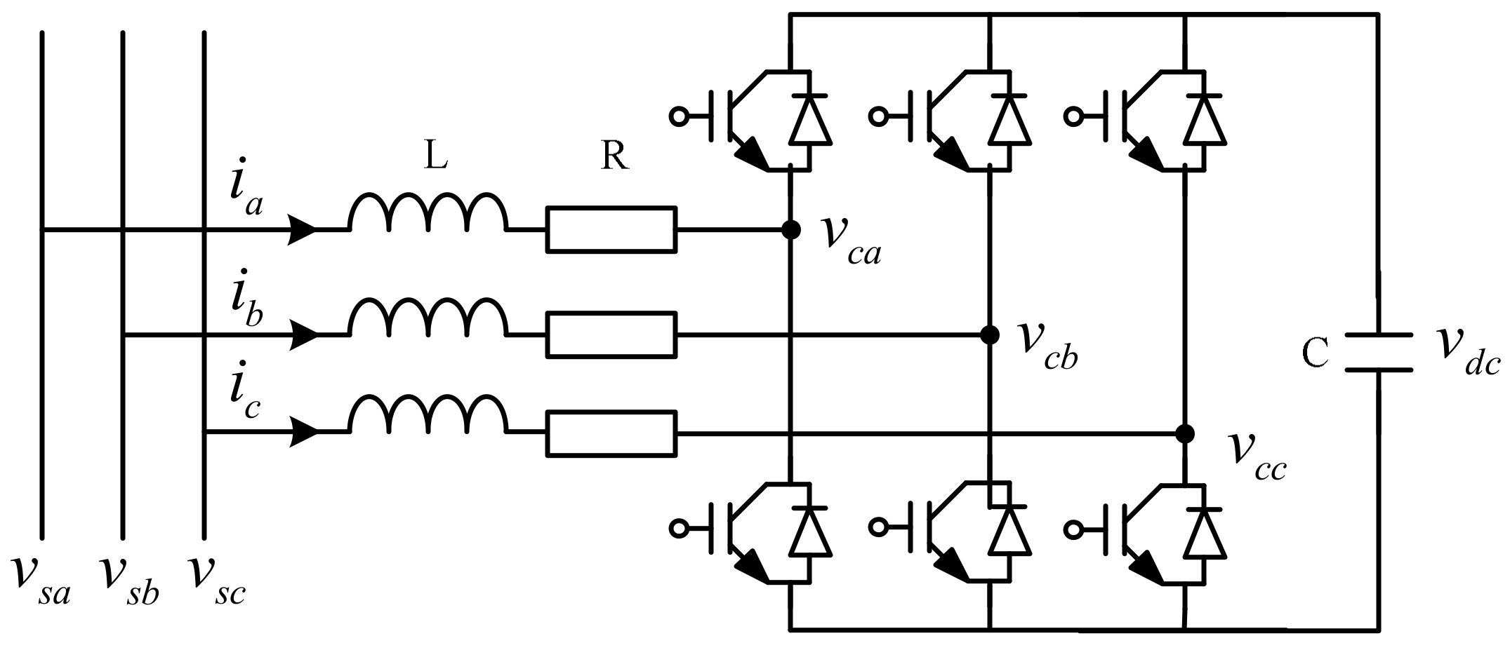
2.1. Mathematical Model

This section describes the operating principle of a STATCOM. In a STATCOM circuit, a self-commutated voltage-source inverter is connected in parallel with a grid through a transformer. The inverter regulates the phase of the output voltage on the ac side [7,8] to achieve continuous input or to absorb the reactive power. Figure 1 illustrates a schematic of a basic STATCOM circuit. To account for the power facility loss, a cascade of R and L, representing the power line resistance and transformer leakage reactance in a typical STATCOM, respectively, is included.
Assume that the voltage vs. in a three-phase system is represented as
v s = v s a v s b v s c = 2   V s sin ω t sin ( ω t 2 π / 3 ) sin ( ω t + 2 π / 3 )
where Vs represents the root mean square of vs, and ω is the angular frequency rate (377 rad/s) Then, the output voltage provided by the STATCOM can be expressed as follows:
v c = v c a v c b v c c = m v d c sin ( ω t δ ) sin ( ω t 2 π / 3 δ ) sin ( ω t + 2 π / 3 δ )
where m is the modulation index and δ is a tunable quantity symbolizing the phase angle between vc and vs. Application of Kirchhoff’s voltage law to the three-phase circuit of a STATCOM (Figure 1) requires that
L d d t i s + R i s = v s v c
where is = [ia ib ic]T. Applying the energy conservation law to both ports of the STATCOM yields the following:
d d t ( 1 2 C v d c 2 ) = v c T i s
By applying Park transform, the three-phase currents are converted into direct axis (d axis), quadrature axis (q axis), and zero axis (0 axis) components perpendicular to the dq reference frame [26,27]. Equations (3) and (4) can be converted to the dq0 synchronous rotating coordinate system:
L d d t i d i q = R ω L ω L R i d i q + v s d v c d v s q v c q
C v d c d d t v d c = 3 2 ( v c d i d + v c q i q )
Assume that the d axis of the synchronous rotating coordinate system represents the system voltage vs; accordingly, the phase angle δ of the output voltage vc can be expressed as follows:
v s d v s q = 2 V s 1 0
v c d v c q = m v d c cos δ sin δ
Back substitution of Equations (7) and (8) into Equations (5) and (6) yields a matrix representation of the STATCOM in time domain
d d t i d i q v d c = R L ω m cos δ L ω R L m sin δ L 3 m 2 C cos δ 3 m 2 C sin δ 0 i d i q v d c + 2 V s L 0 0
Through the mathematical model, the reactive power drawn and supplied by a compensator can be derived as follows:
Q = 3 V s 2 2 R sin 2 δ
According to Equation (10), when δ > 0, that is, Q > 0, reactive power is drawn by the device; otherwise, it is supplied by the device. In other words, the operation of a STATCOM depends on the value of the phase angle δ.

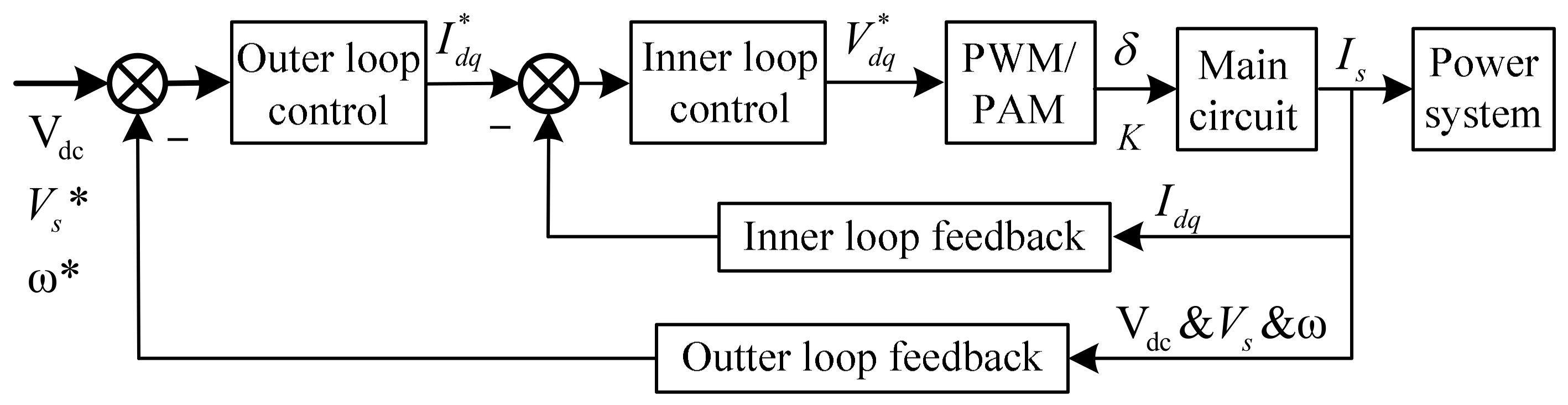
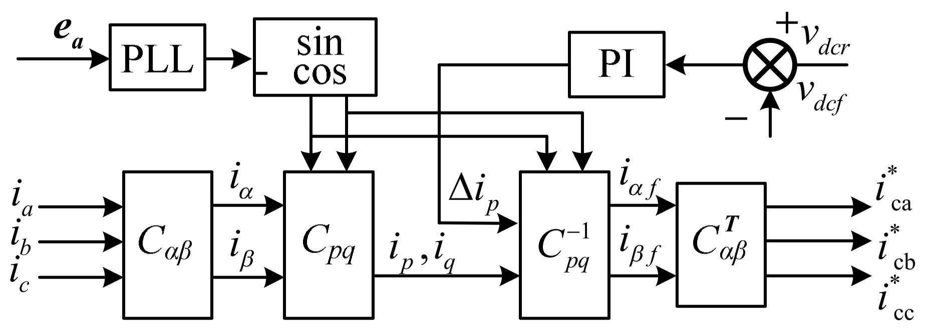
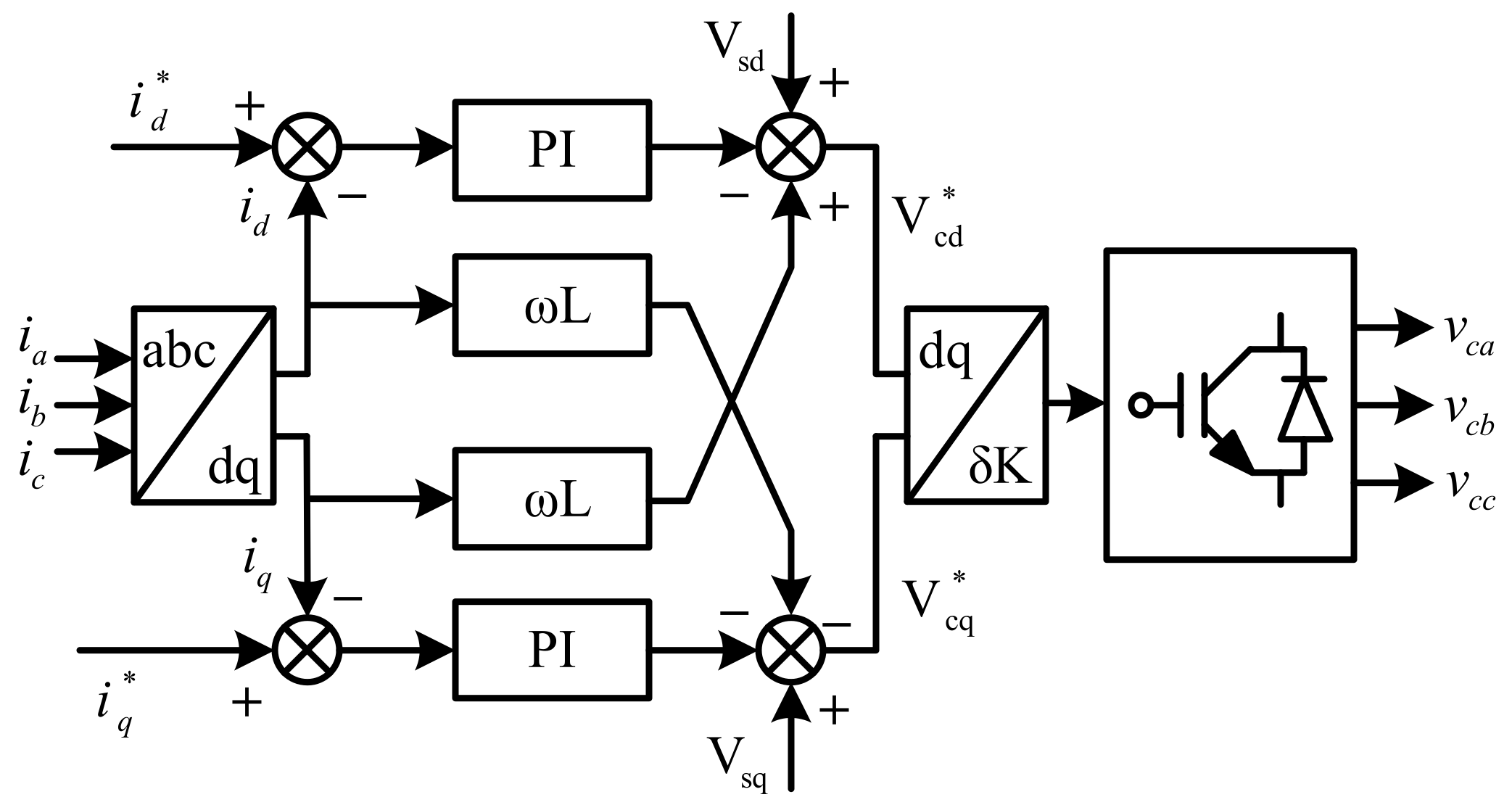
2.2. Decoupling Dual-loop Current Control

As illustrated in Figure 2, a STATCOM controller design involves two levels: an inner loop and outer loop. As a parallel reactive power compensator, a STATCOM aims to provide a power system with a continuous reactive current such that the voltage can be regulated as intended. In practical applications, numerous quantities such as the system current, power angle, and rotator speed are considered to improve the system performance (e.g., signal filtering and power oscillation damping in the outer feedback loop) [21]. The current instruction yielded by the outer loop controller is used as an instruction to the inner loop controller to achieve efficient and precise mapping between i*dq and the compensation current is.
The response tracking performance at the facility level of a STATCOM and the compensation performance at the system level are reflected in the performance of the inner and outer loop controllers, respectively. The outer loop controller adapts to various power system applications, and the inner loop controller affects the overall performance of the facility. This study presents a dual-loop current control strategy based on the proposed STATCOM model.

2.2.1. Inner Loop Current Control

Because id and iq in Equation (5) cannot be decoupled, the state matrix is diagonalized in an attempt to independently control the real and reactive power through the compensator [8]. Accordingly, the introduction of the variables x1 and x2 into Equation (5) yields the following:
d d t i d i q = R L 0 0 R L i d i q + x 1 x 2
Equation (5) into Equation (11) yields the following:
v c d = v s d L x 1 + ω L i q v c q = v s q L x 2 ω L i d
In this study, particle swarm optimization (PSO) was applied to obtain the voltage PI parameters. PSO produces no overlapping and does not require mutation calculation [28]. The search can be performed using the speed of the particle. Over the development of several generations, only the most optimized particle can transmit information to the other particles, and the research speed is rapid [29,30]. It has excellent robustness and can be used in different application environments with minor modifications. x1 and x2 can be treated as the control variables of the AC voltage outputs vcd and vcq, respectively, provided by the STATCOM [8]. Accordingly, the proportional integral PI control law can be defined as follows:
x 1 = ( K P d + K I d s ) ( i d * i d ) x 2 = ( K P q + K I q s ) ( i q * i q )
Consequently, the decoupling inner loop control for the STATCOM is derived, as illustrated in Figure 3. The current instructions i*d and i*q are provided by the outer loop control, where i*q reflects the variation in the capacitor voltage vdc on the dc side. On the basis of the instantaneous reactive power theory, m and δ can be expressed in terms of vcd and vcq as follows:
m = v c d 2 + v c q 2 v d c
δ = tan 1 ( v c q v c d )

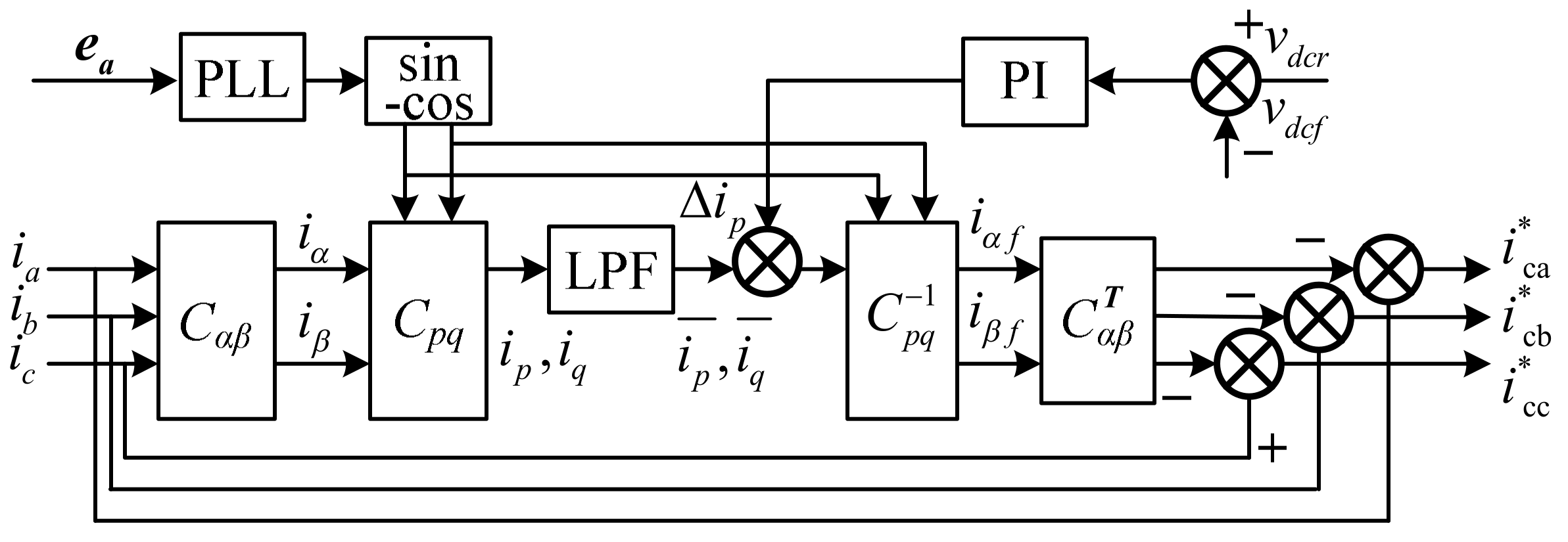
2.2.2. Current Instruction Generation for Outer Loop Current Control

Unlike the conventional definition of a time averaged power, the instantaneous power, both reactive and real, is well defined in the instantaneous reactive power. Presented in Figure 4 is the block diagram of a reactive power detector for the fundamental and higher harmonic components. Phase lock loop (PLL) is a control system that generates an output signal whose phase is related to the phase of an input signal [31] C α β is used to convert the equation from ia, ib, ic to iα, iβ values, which is based on Park transform. C α β T is the transpose of C α β , C pq is the real and reactive current convert matrix, and C pq 1 is the inverse of C pq . The grid voltage ea is employed in a PLL to yield a synchronous signal sin ωt and the corresponding−cos ωt, and then the real and reactive power components ip and iq are determined by taking the transform of the load current [22].
Subsequently, both DC components i p ¯ and i q ¯ are yielded as the output of a low pass filter (LPF). Consider that the channels ip and iq represent the real and reactive power, respectively; the final current instruction, which comprises the fundamental and higher harmonic reactive power components, is provided when the channel iq is disconnected. The difference between the DC-side capacitor voltage vdcr and the feedback signal vdcf is derived and applied to a PI controller, after which Δip is superimposed onto the fundamental harmonic real power branch. Thus, the capacitor voltage is regulated by the energy interchange between the dc and AC-side of the STATCOM, as displayed in Figure 4.
In Figure 4, all the variables are related as follows:
i p i q = C p q C α β i a i b i c = C p q i α i β
where
C p q = sin ω t cos ω t cos ω t sin ω t
C α β = 2 3 1 1 / 2 1 / 2 0 3 / 2 3 / 2
The ip represents the sum of the real power and DC-side Δip, expressed as
i p = i ¯ p Δ i p
Disconnection of the reactive power channel yields
i a f i b f i c f = C α β T i α f i β f = C α β T C p q i p 0
Finally, the current instruction for the compensation can be written as follows:
i c a * i c b * i c c * = i a i b i c i a f i b f i c f
However, the aforementioned control scheme has a major limitation when applied to a high-power STATCOM because it involves the highly complex task of controlling a high-power switching device, such as a gate turn-off thyristor. Moreover, a higher harmonic component cannot be detected precisely owing to the switching frequency limit of the device, and unintended harmonics would be embedded into the output voltage. Therefore, the mentioned control approach is applicable only to a low- or medium-power STATCOM.
Because the reactive power of the fundamental harmonic contributes the most to the entire reactive power consumption, the reactive power can be compensated to a satisfactory extent in case the compensation is conducted on only the fundamental harmonic component. This compensatory approach entails extracting the reactive power associated with the fundamental harmonic from the load current and then converting it into the current instruction by taking the inverse transform. Figure 5 displays a block diagram of the derivation of the inverse transform of the real power to regulate the DC-side capacitor voltage. Disconnection of the transformed channel ip yields the instruction signals for the compensation current as follows:
i c a * i c b * i c c * = C α β T i α f i β f = C α β T C p q Δ i p i q
The greatest advantage of this approach over the aforementioned approach is that it does not necessitate the detection of any harmonic component; that is, the switching frequency limit is not a concern. This permits the design of a high-capacity power system by using a high-power thyristor as a switch. Consequently, the output voltage contains a large number of harmonics, leading to a reduced utilization rate of the DC component—a problem that can be solved using a multilevel technique.

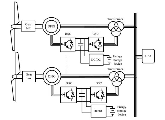
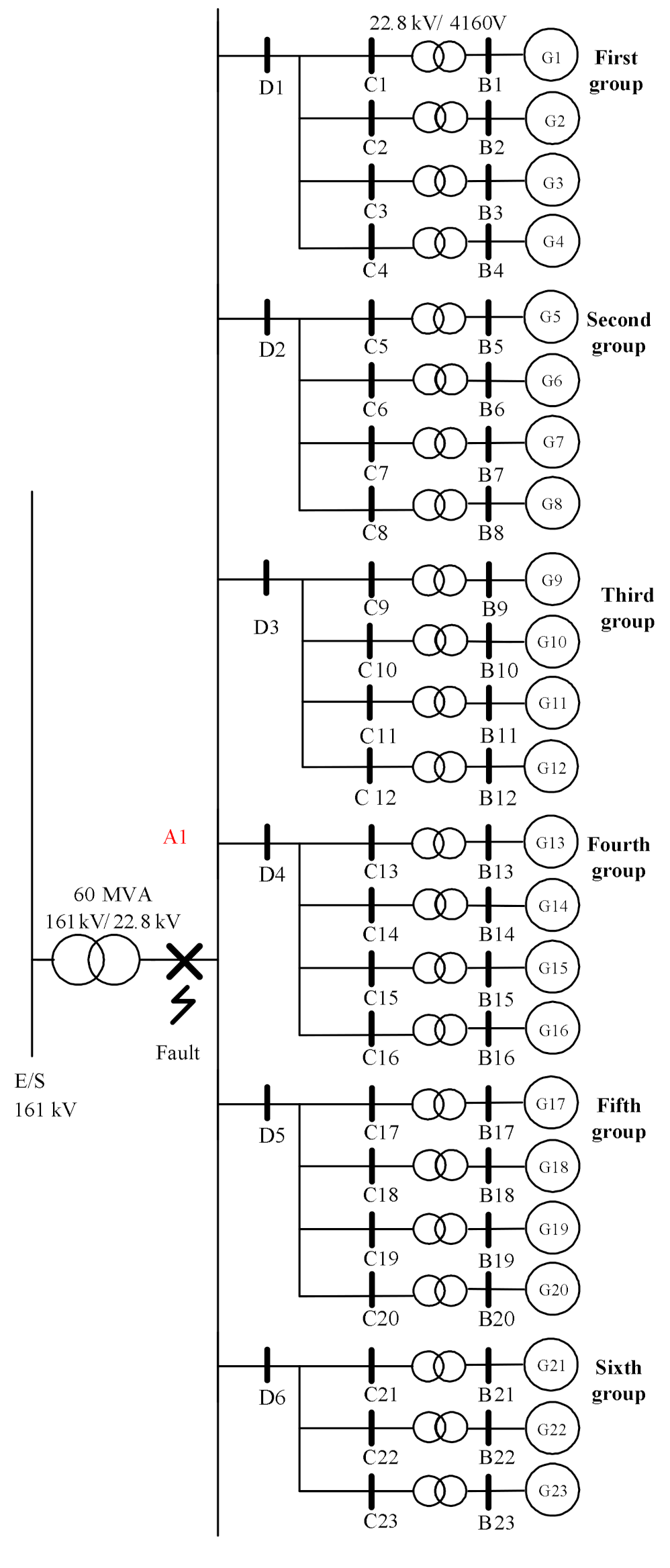
3. Case Study on Wind Power System

The test objects employed in this work included 23 sets of 3.6 MW DFIGs, with a total capacity of 82.8 MW, erected at the wind farm in Changhua Coastal Industrial Park, Taiwan. The generators were divided into six groups, five of which comprised four wind turbine generators, and the sixth group contained three wind turbine generators. The transmission line lengths of the groups are presented in Table 1. As illustrated in Figure 6, the output voltage provided by each generator (4160 V) was boosted to 22.8 kV by using a 4160 V/22.8 kV step-up transformer connected in parallel with PCC through power cables spanning several kilometers. Then, the 22.8 kV voltage was applied to a 161 kV power grid compound transmission line system by using a 22.8 kV/161 kV step-up transformer. The parameters required for simulations, 4.16 kV/22.8 kV and 2.8 kV/161 kV step-up transformers, and the transmission line are tabulated in Table 2 and Table 3 [25].

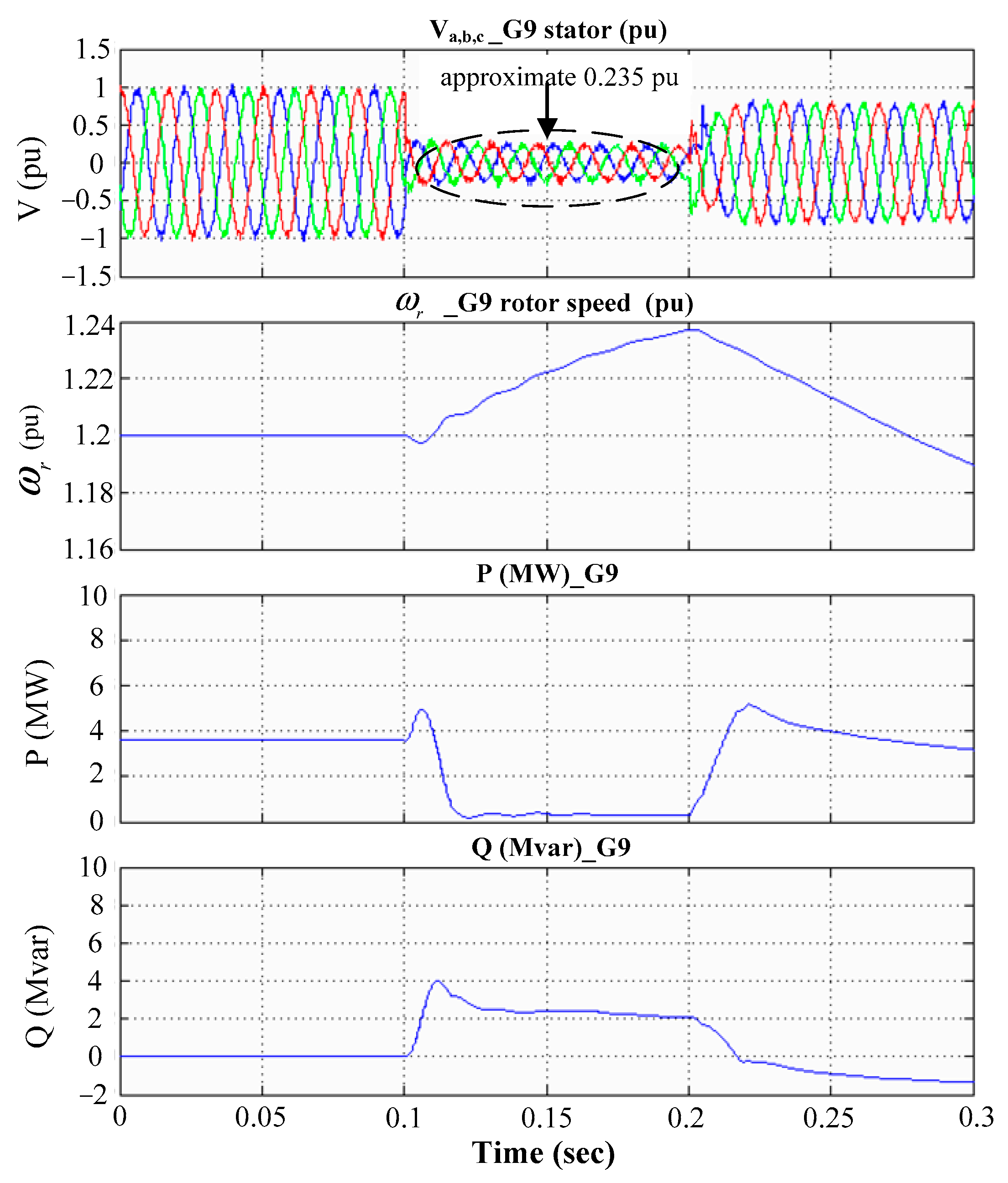
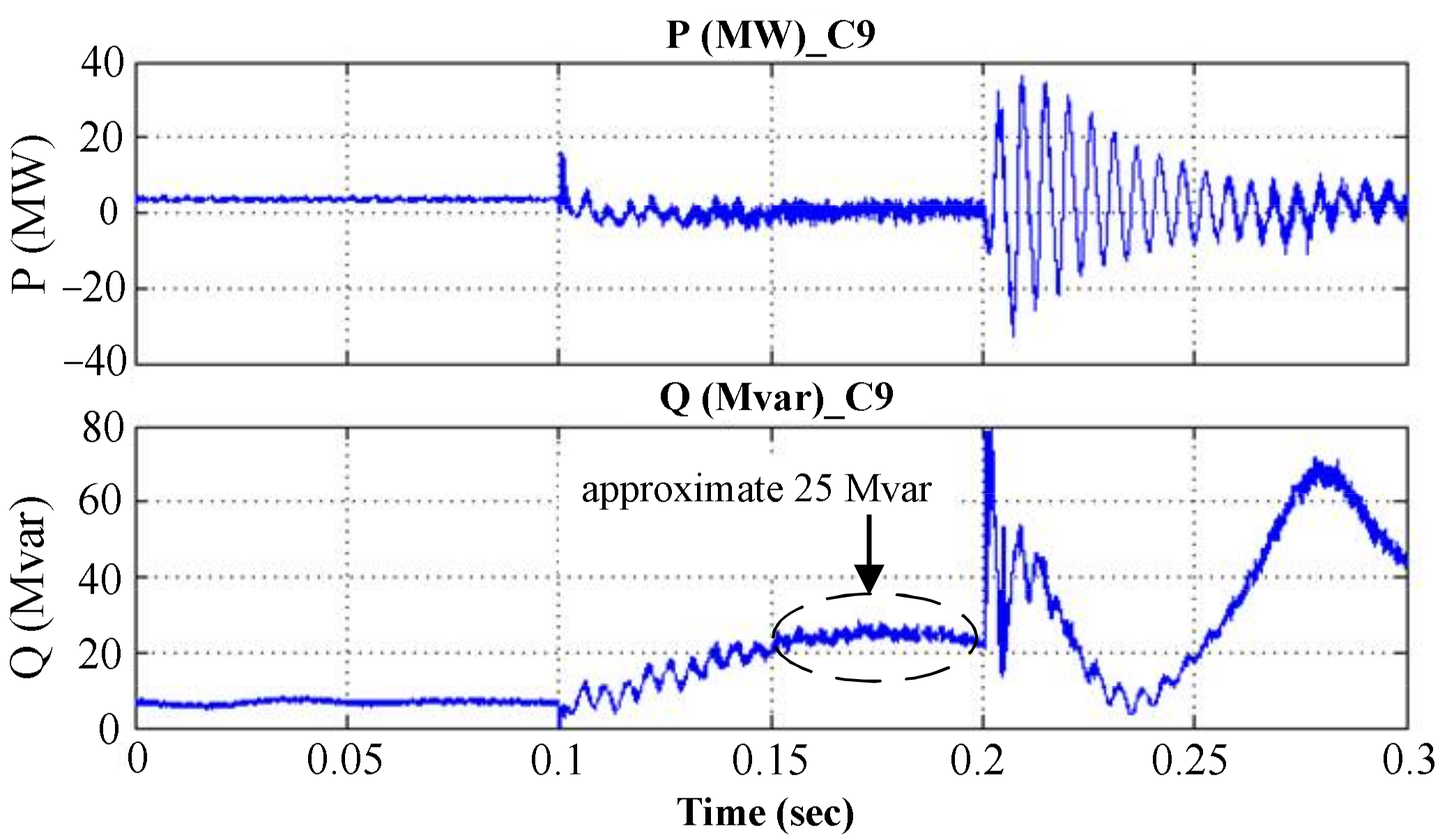
3.1. Three Phase Ground Fault Analysis

This study simulated a scenario involving the occurrence of a three-phase ground fault at t = 0.1 s in bus A1 and the removal of the ground fault at t = 0.2 s. The simulation revealed the transient-state response across the various wind turbine generators and buses. The simulation was performed on a reasonable premise: the wind speed was maintained at 15 m/s, the rotator was operated at 1.2 per unit (pu), and all wind power generators were operated in the over-synchronous speed mode. As presented in Table 1, with the shortest transmission line length, the turbines in the third group had the shortest distance from the fault location, meaning that they were affected the most. Therefore, the transient-state response of buses D3 and C9 and that of the generator G9 (treated as a reference) were explored for further investigation of the STATCOM.
The transient-state responses of voltage, current, real power, and reactive power to a three-phase ground fault on bus A1 are displayed in Figure 7; the voltage and the real and reactive power dropped to zero at the instant the fault occurred, but the current increased up to a maximum value of 4.18 pu.
The transient-state responses of voltage, current, real power, and reactive power on bus D3 are presented in Figure 8. When a fault occurred, the voltage magnitude dropped to approximately 0.103 pu, the current increased to a maximum value of 0.68 pu, and the real power dropped to 1 MW. However, a reactive power of 4 Mvar was provided by one of the generators to the power grid, with the symbols “−” and “+” representing the reactive power provided by the power grid and by a wind turbine generator, respectively.
The transient-state responses on bus C9 are plotted in Figure 9. When the fault occurred, the voltage dropped to 0.103 pu, the maximum current was 0.18 pu, and real power decreased from 3.6 to 0.3 MW. In addition, a reactive power of 1 Mvar was supplied from the winder power generators to the power grid to compensate for the loss and to increase the bus voltage.
The G9 transient-state responses of stator voltage, rotator speed, real power, and reactive power are presented in Figure 10. In the event of a system malfunction, on account of a drop in the stator voltage, the power generator set failed to supply the intended amount of electricity to the power grid, leading to a drop (from 3.6 to 0.3 MW) in the real power supplied to the grid. An excessive amount of electricity supplied by a generator sped up the rotator revolution to approximately 1.237 pu. For compensation, 2.2 Mvar of reactive power was provided to the grid for boosting the voltage to 0.235 pu on bus G9.

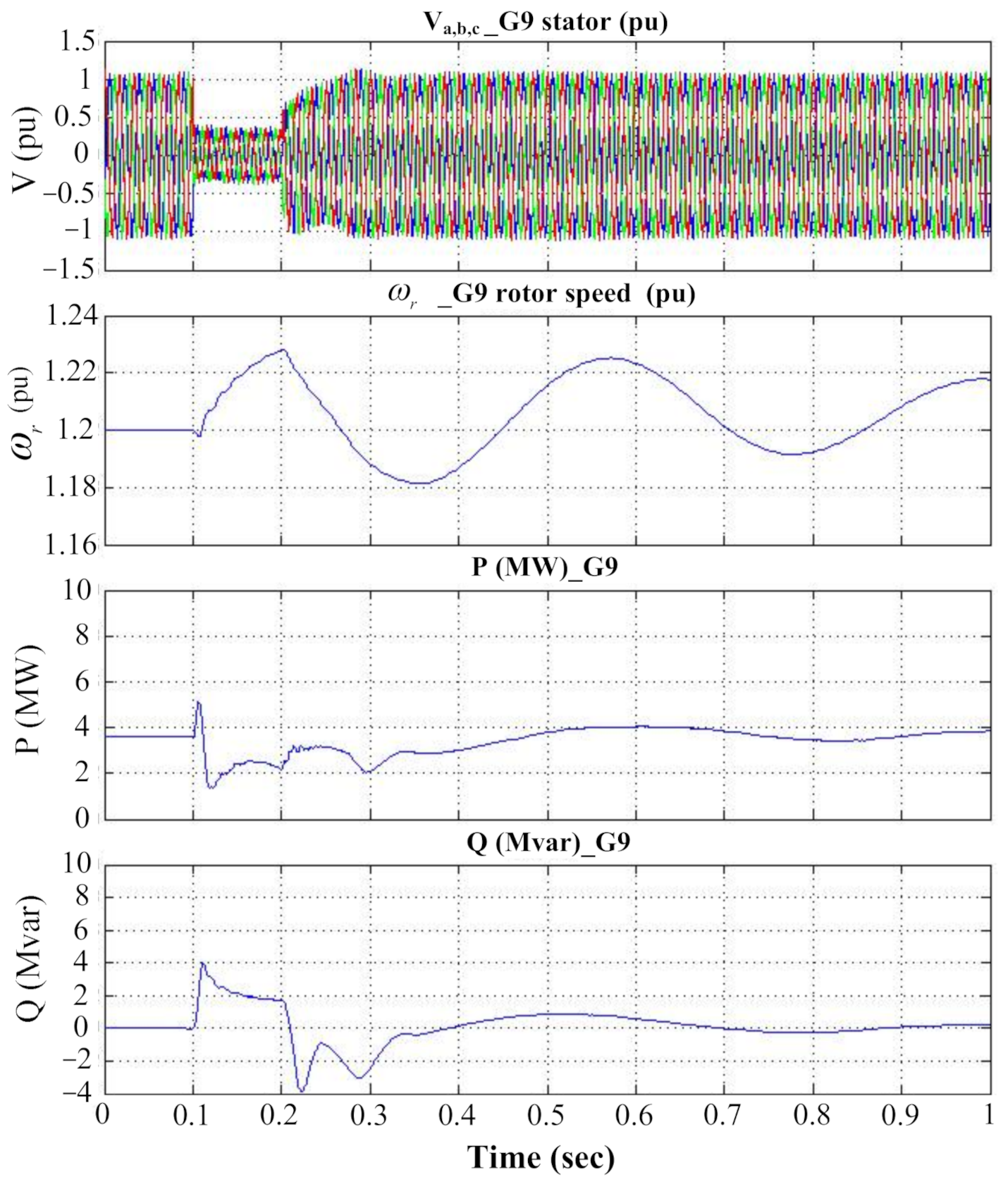
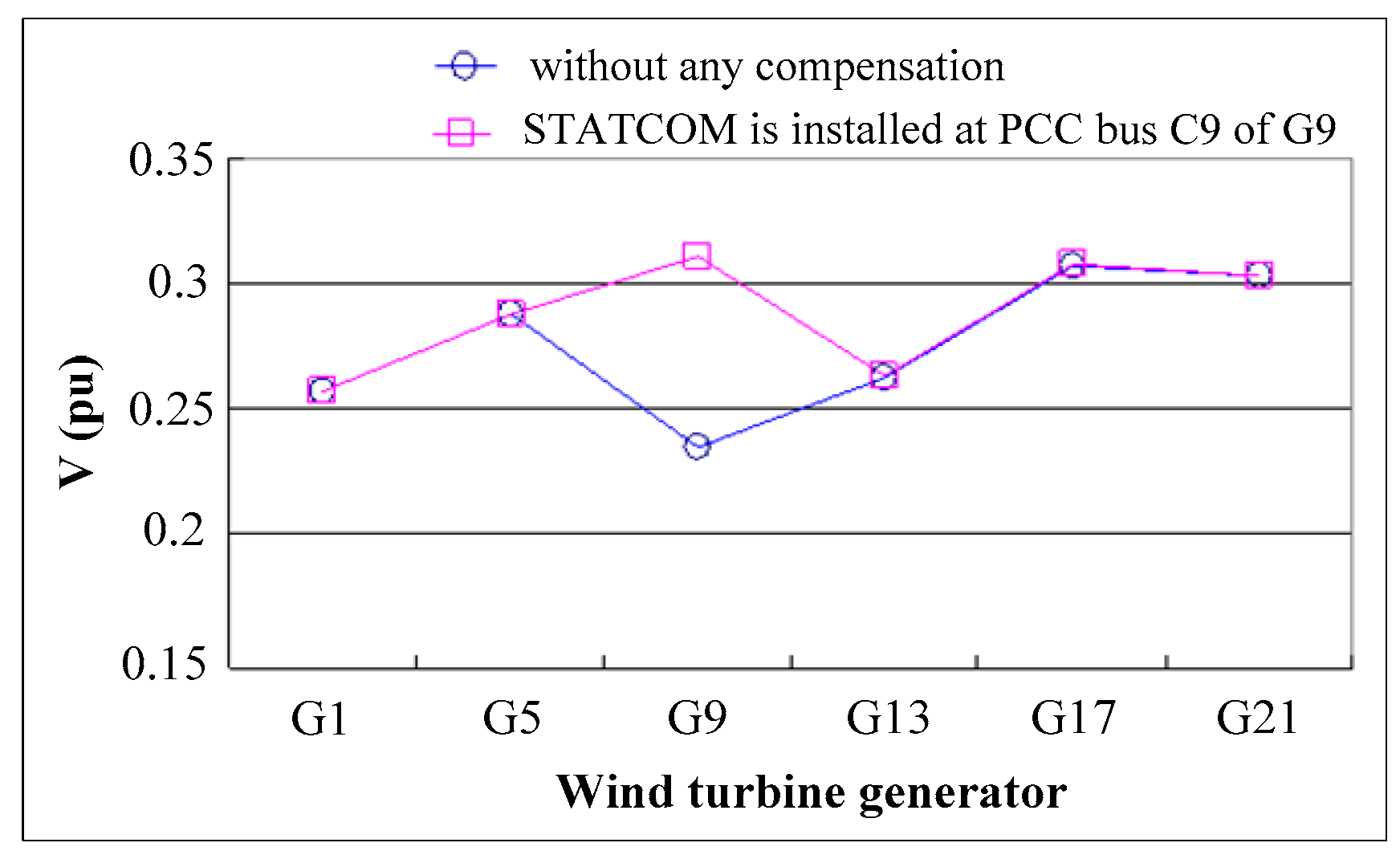
3.2. Responses in the Presence of a STATCOM

As mentioned, the third group of generators had the greatest vulnerability to the impact because it was closest to the fault location. Accordingly, the effects of a STATCOM on a wind turbine generator were investigated in three cases: In the first case, the STATCOM was installed at the PCC bus C9 of G9. In the second case, the STATCOM was installed at the feeder termination bus D3 of the third group. Finally, in the third case, the STATCOM was installed at the feeder termination bus D1–D6 of each group.

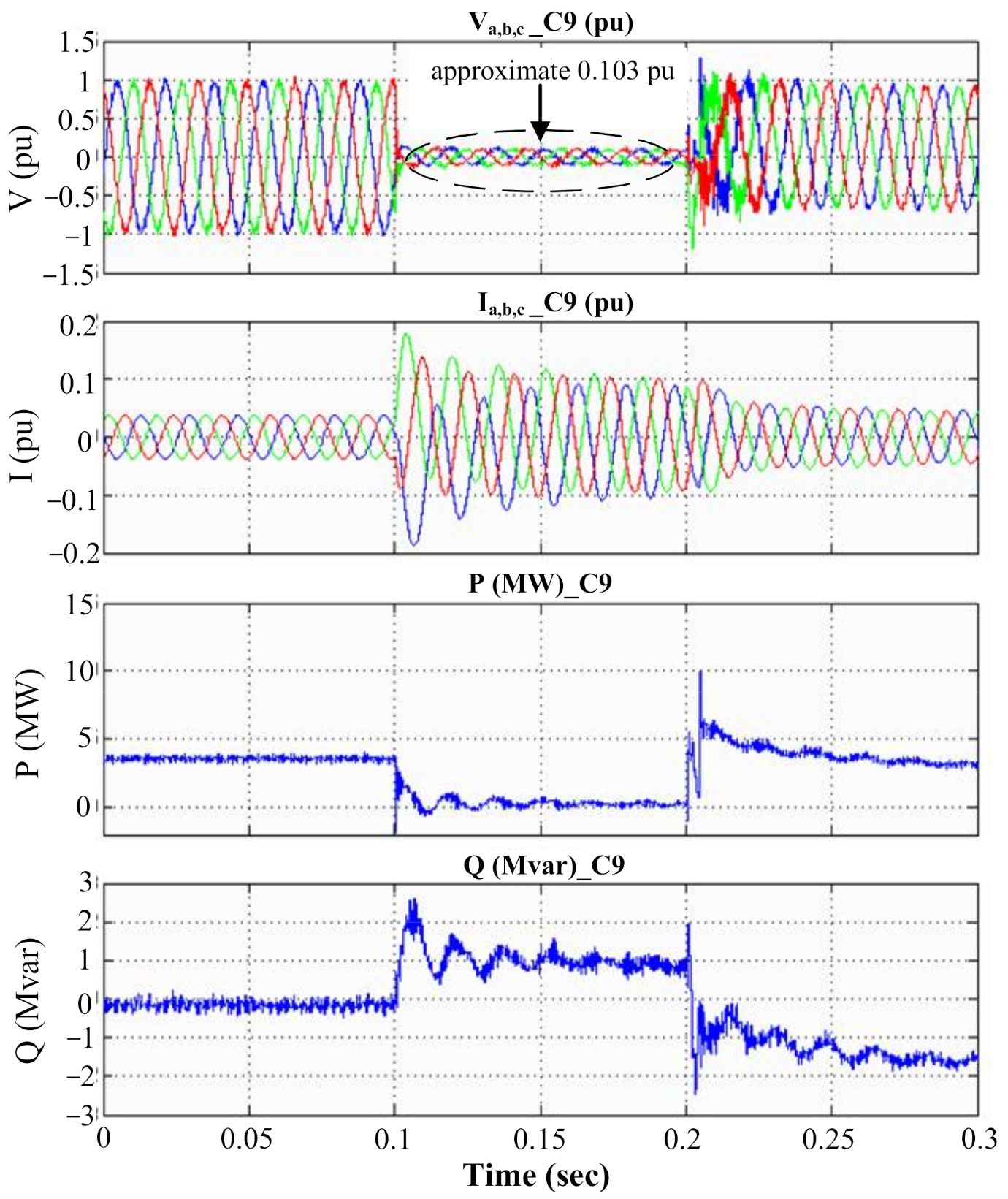
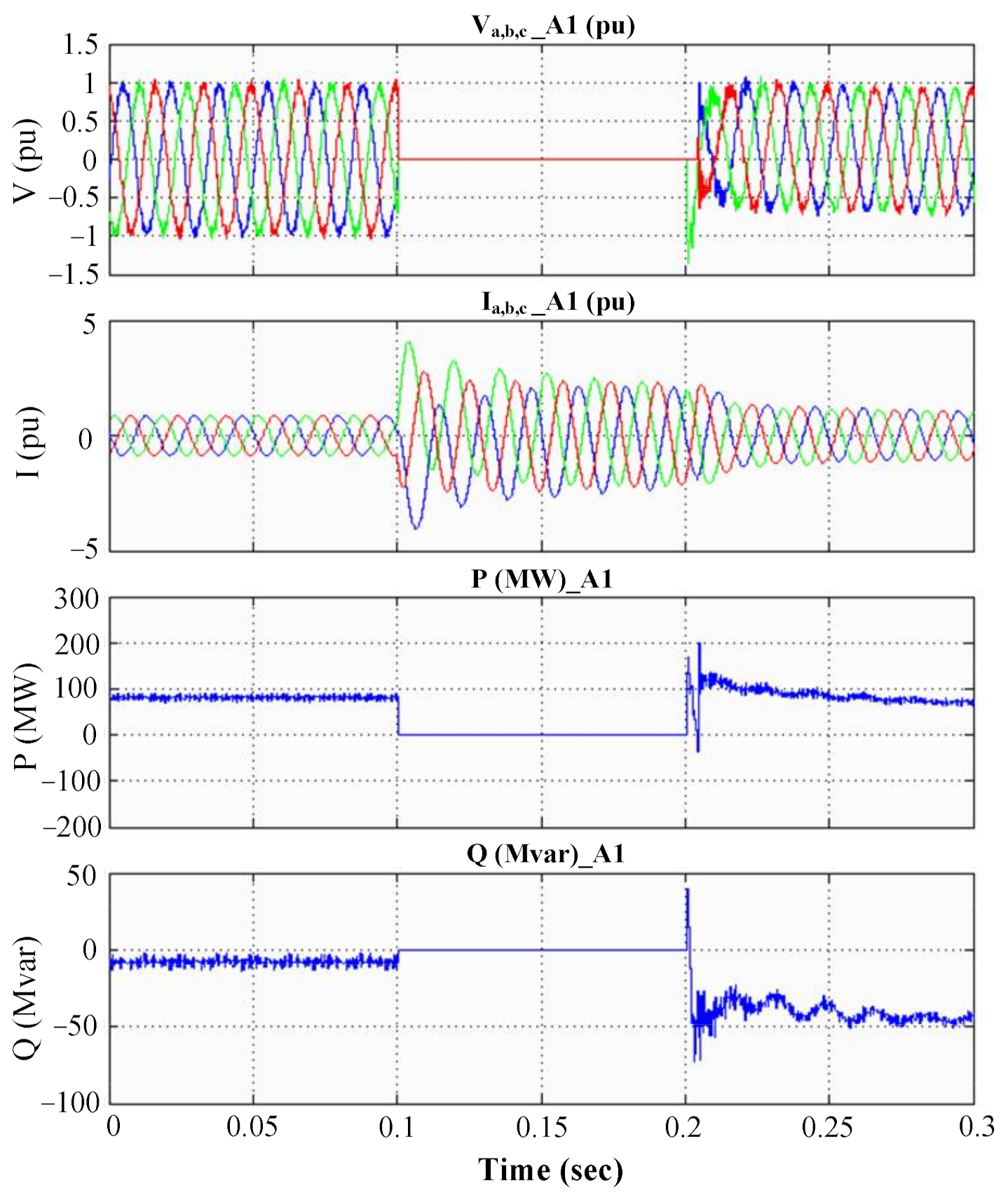
3.2.1. Case 1—STATCOM Installed at the PCC Bus C9 of G9

The plots of real and reactive power in case 1 are shown in Figure 11. When a fault occurred, zero real power was delivered to C9, but the STATCOM compensated for the reactive power on C9 by up to 25 Mvar. Accordingly, the line voltage increased. The simulated responses of the G9 stator voltage, rotator speed, and real and reactive power for a time span of 1 s are presented in Figure 12. The use of the STATCOM promoted the generator voltage to 0.311 pu, which increased the electromagnetic torque and inhibited the increase in the rotator speed. The rotor speed decreased from 1.237 pu (without any compensation) to 1.228 pu (after compensation). An output power of 2.5 MW was well maintained. Thus, the installation of the STATCOM at C9 of G9 helped maintain the LVRT capability and prevented overspeeding of the rotator; that is, a balance between mechanic and electromagnetic torque was reached to avoid generator tripping. After the fault was fixed at t = 0.2 s, the steady-state response recovered following an interval of oscillation. Specifically, the STATCOM installed at bus C9 of G9 enabled an uninterrupted power supply system.
The first wind turbine generator erected in each group incurred the most severe impact from the fault. A comparison of the output voltage supplied by the first generator in each group is provided in Figure 13. The comparison results indicated that the installation of the STATCOM at bus C9 of G9 increased the voltage from 0.235 to 0.311 pu when the fault occurred but did not demonstrate the influence on the output voltage rendered by other generators. Thus, the STATCOM improved only the transient-state response of the compensated power generator. In contrast to the results in Figure 11, as illustrated in Figure 12, a reactive power of only 2 Mvar was delivered, but the voltage levels on buses C9 and C10–C12 were largely elevated due to the contribution of a 25-Mvar compensation to bus C9.

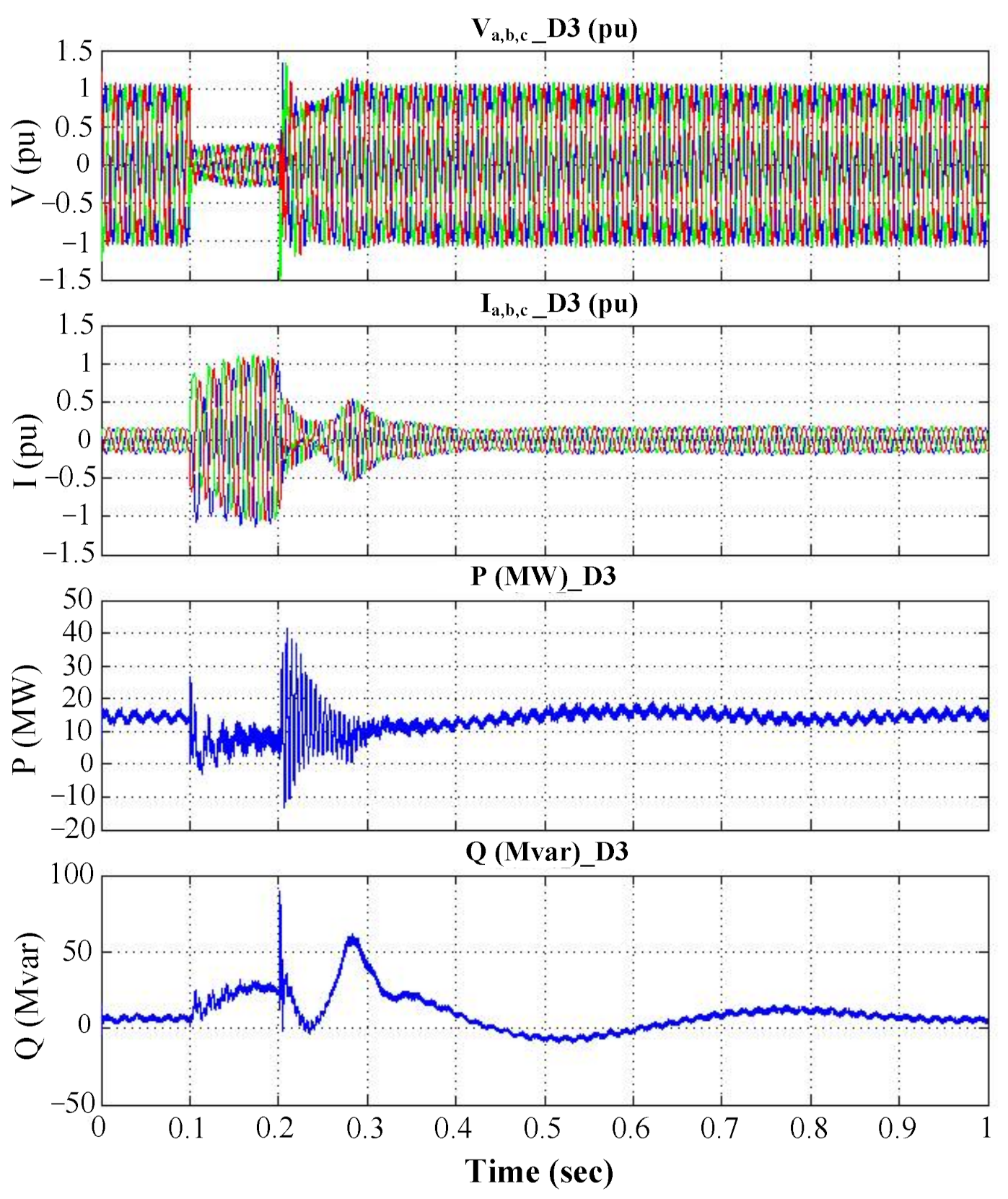
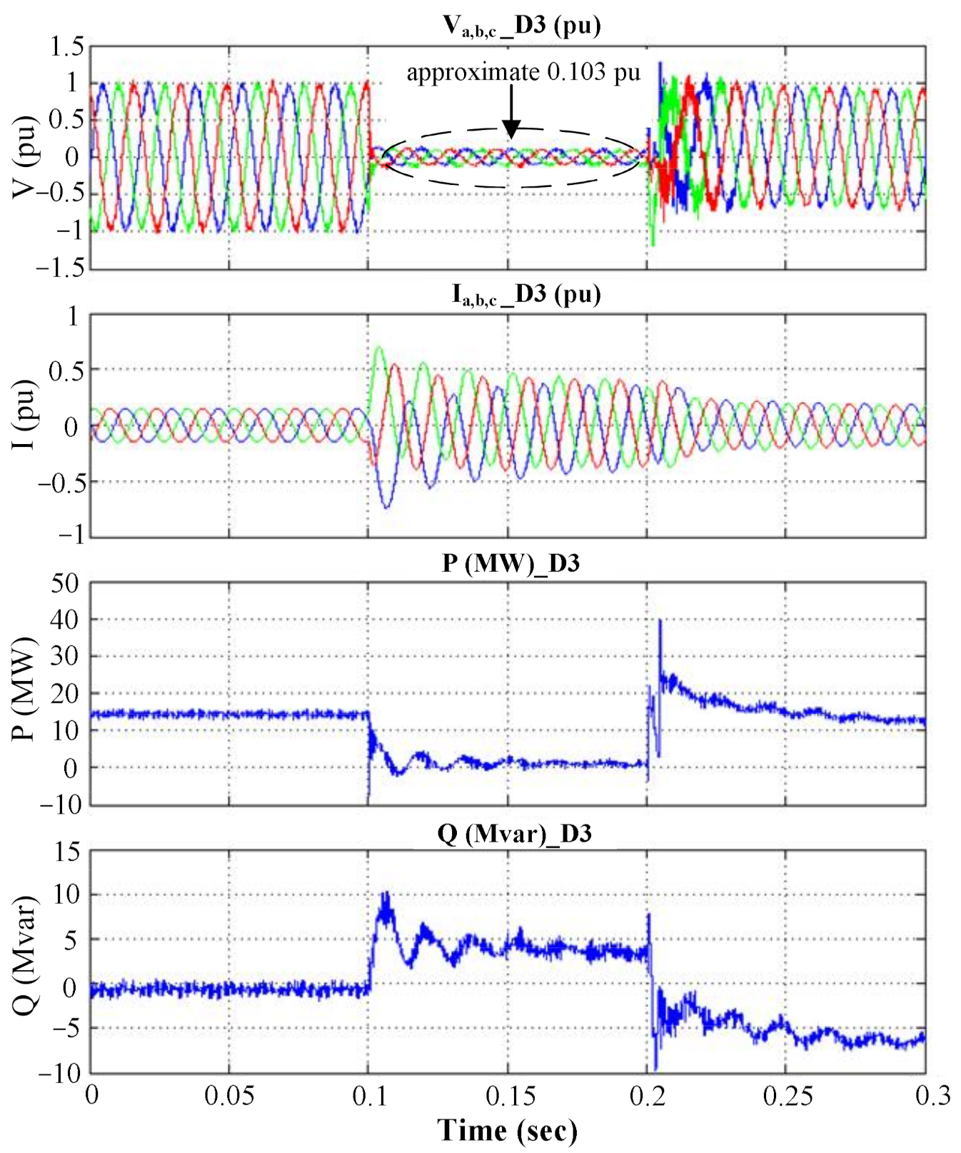
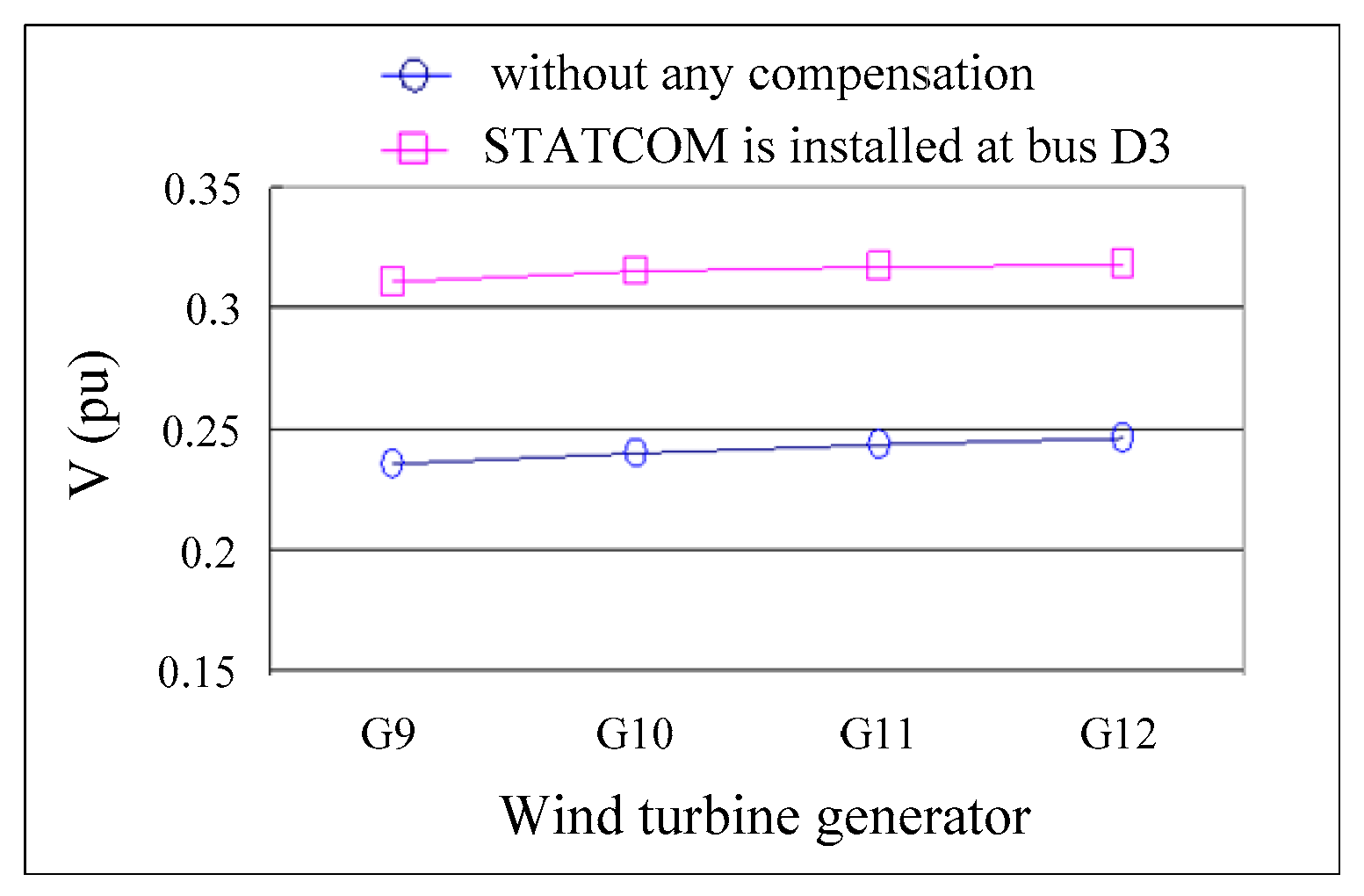
3.2.2. Case 2—STATCOM Installed at Feeder Termination Bus D3 of Third Group

The simulated responses of the stator voltage, current, and real and reactive power for a time span of 1 s for this case are presented in Figure 14. During a fault event, the real power on bus D3 was maintained at approximately 8 MW due to the contribution by generators G9–G12. In addition, an elevated reactive power of approximately 25 Mvar was noted on bus D3 due to the contribution of the STATCOM. As displayed in Figure 14, the transient-state responses of the generators and respective LVRT abilities in the third set improved. After the fault removal at t = 0.2 s, the steady-state response recovered in the wake of an oscillation.
For comparison, the output voltages provided by generators G9–G12 in the third group in the course of the fault event are plotted in Figure 15. In compliance with the safety requirements for an LVRT in a wind power generation facility, a wind turbine generator must endure operation for 1 s at a low voltage level; that is, the output voltage must be maintained above 0.3 pu. A difference was seen between an uncompensated case and this STATCOM-compensated power system, and all the output voltage levels were effectively regulated to meet the power requirement.

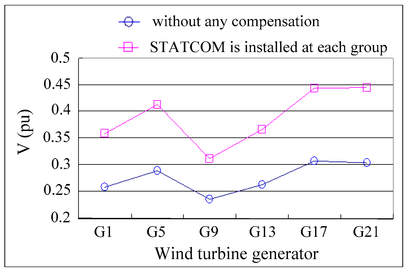
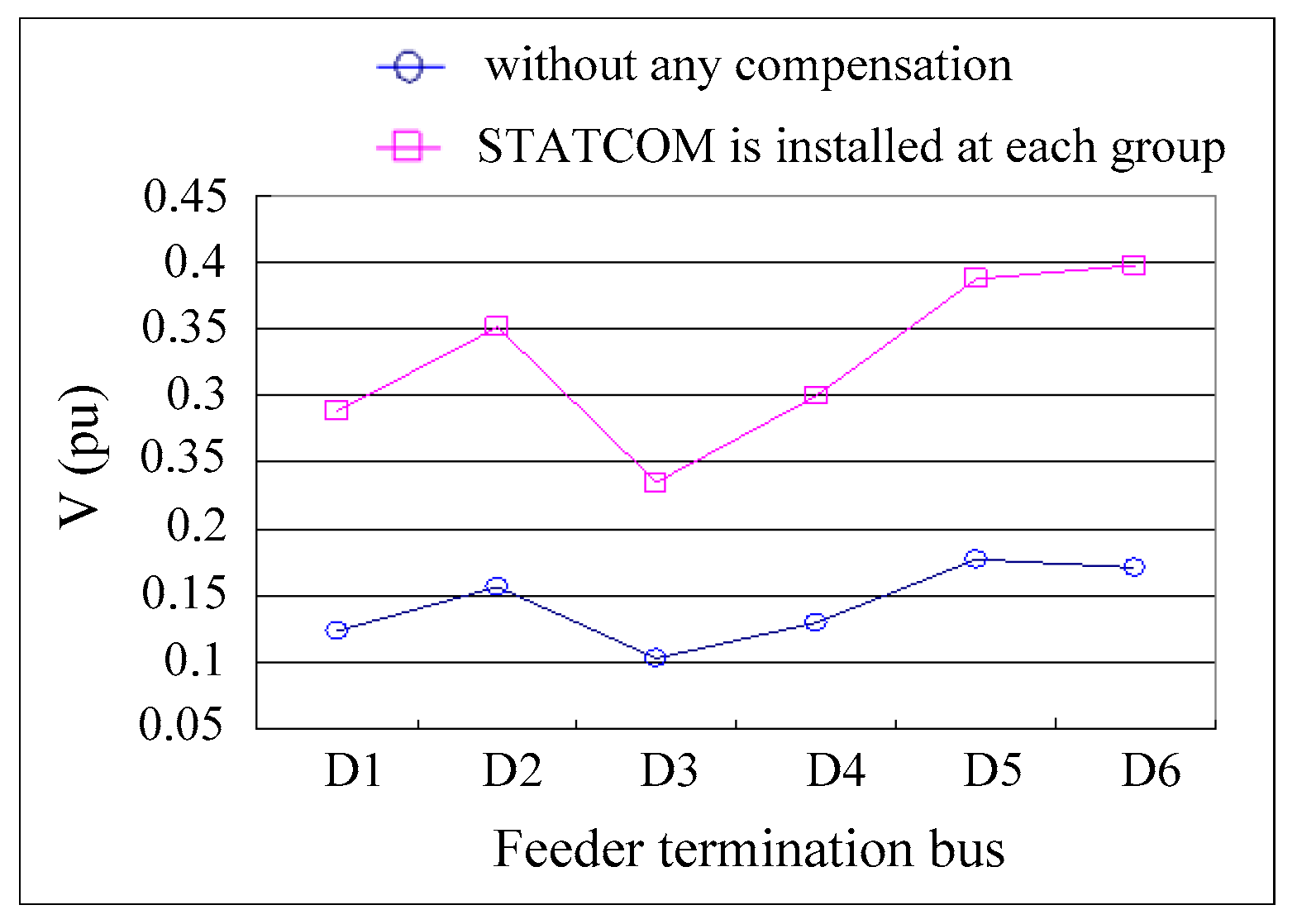
3.2.3. Case 3—STATCOM Installed at the Feeder Termination Bus D1–D6 of Each Group

According to the LVRT requirement stipulated in the parallel connection regulation by the Taiwan Power Company for renewable energy sources, a wind power generation facility must be able to operate for 0.5 s when the output voltage plunges to 15% of the voltage rating in the event of a power system malfunction [32]. As indicated in Figure 16, in the uncompensated case, the feeder termination bus D1–D6 voltages did not reach 15% of the rated voltage because of a shorter transmission line length (i.e., a smaller value capacitance). In this case, dynamic reactive power compensation was achieved by the STATCOM to individual groups during the fault event. The LVRT capability was enhanced, and feeder termination bus D1–D6 voltage in each group exceeded 0.2 pu, as presented in Figure 16.
In consideration of LVRT, uninterrupted operation for a minimum of 1 s is required for a power generator; that is, a minimum of 0.3 pu of output voltage must be maintained, which is evident in Figure 17.

4. Conclusions

In this study, fault analysis was performed, and transient performance improvement of wind power systems was investigated. A model of the Changhua Coastal Industrial Park commercial wind farm was constructed using Simulink, and the transient responses of the wind farm during ground faults were simulated. Utilizing the innate reactive power compensation ability of DFIGs, this study proposes a real-time reactive power control strategy as an effective approach for regulating the system output voltage by using a STATCOM against a fault event. The analysis and simulation results reveal that the fault ride-through capability improved considerably, and rapid recovery of power generator output voltage was observed upon fault removal. Furthermore, the effect of the STATCOM installation location on the stability of the system output voltage was explored for practical applications.

Author Contributions

F.-C.G. conceived and designed the study, studied and tested the algorithm, and wrote the original draft; H.-C.C. contributed to the writing, reviewing, editing, resource planning, supervision, and project administration processes. Both coauthors collaborated with respect to the interpretation of the results and in the preparation of the manuscript. Both authors have read and agreed to the published version of the manuscript.

Funding

The research was supported by the Ministry of Science and Technology, Taiwan, under contract numbers: MOST 110-2221-E-167-012 and MOST 108-2221-E-167-017.

Institutional Review Board Statement

Not applicable.

Informed Consent Statement

Not applicable.

Data Availability Statement

Not applicable.

Acknowledgments

Authors thank for the financial support of the Ministry of Science and Technology.

Conflicts of Interest

The authors declare no conflict of interest.

References

  1. Guo, S.; Miao, S.; Zhao, H.; Yin, H.; Wang, Z. A novel fault location method of a 35-kV high-reliability distribution network using wavelet filter-S transform. Energies 2020, 13, 5118. [Google Scholar] [CrossRef]
  2. Martini, F.; Contreras Montoya, L.T.; Ilinca, A. Review of wind turbine icing modelling approaches. Energies 2021, 14, 5207. [Google Scholar] [CrossRef]
  3. Song, X.W.; Liu, D.; Polinder, H.; Mijatovic, N.; Holboll, J.; Jensen, B.B. Short circuits of a 10-MW high-temperature superconducting wind turbine generator. IEEE Trans. Appl. Supercond. 2017, 27, 5201505. [Google Scholar] [CrossRef] [Green Version]
  4. Zhao, H.S.; Cheng, L.L. Open-switch fault-diagnostic method for back-to-back converters of a doubly fed wind power generation system. IEEE Trans. Power Electr. 2018, 33, 3452–3461. [Google Scholar] [CrossRef]
  5. Wang, L.; Truong, D.N. Stability enhancement of a power system with a PMSG-based and a DFIG-based offshore wind farm using a SVC with an adaptive-network-based fuzzy inference system. IEEE Trans. Ind. Electron. 2013, 60, 2799–2807. [Google Scholar] [CrossRef]
  6. Bian, X.Y.; Geng, Y.; Lo, K.L.; Fu, Y.; Zhou, Q.B. Coordination of PSSs and SVC damping controller to improve probabilistic small-signal stability of power system with wind farm integration. IEEE Trans. Power Syst. 2016, 31, 2371–2382. [Google Scholar] [CrossRef] [Green Version]
  7. Wang, T.; Song, G.B.; Hussain, K.S.T. Three-phase adaptive auto-reclosing for single outgoing line of wind farm based on active detection from STATCOM. IEEE Trans. Power Deliv. 2020, 35, 1918–1927. [Google Scholar] [CrossRef]
  8. Ibrahim, A.M.; Gawish, S.A.; El-Amary, N.H.; Sharaf, S.M. STATCOM controller design and experimental investigation for wind generation system. IEEE Access 2019, 7, 150453–150461. [Google Scholar] [CrossRef]
  9. Liu, J.W.; Xu, Y.; Qiu, J.; Dong, Z.Y.; Wong, K.P. Non-network solution coordinated voltage stability enhancement with STATCOM and UVLS for wind-penetrated power system. IEEE Trans. Sustain. Energy 2020, 11, 1559–1568. [Google Scholar] [CrossRef]
  10. Luo, C.; Ma, X.; Yang, L.; Li, Y.; Yang, X.; Ren, J.; Zhang, Y. A modified grid-connected inverter topology for power oscillation suppression under unbalanced grid voltage faults. Energies 2021, 14, 5057. [Google Scholar] [CrossRef]
  11. Chishti, F.; Murshid, S.; Singh, B. Robust normalized mixed-norm adaptive control scheme for PQ improvement at PCC of a remotely located wind-solar PV-BES microgrid. IEEE Trans. Ind. Inform. 2020, 16, 1708–1721. [Google Scholar] [CrossRef]
  12. Ockhuis, D.K.; Kamper, M. Potential of slip synchronous wind turbine systems: Grid support and mechanical load mitigation. Energies 2021, 14, 4995. [Google Scholar] [CrossRef]
  13. Jin, Y.Q.; Wu, D.M.; Ju, P.; Rehtanz, C.; Wu, F.; Pan, X.P. Modeling of wind speeds inside a wind farm with application to wind farm aggregate modeling considering LVRT characteristic. IEEE Trans. Energy Convers. 2020, 35, 508–519. [Google Scholar] [CrossRef]
  14. Xiang, D.W.; Turu, J.C.; Muratel, S.M.; Wang, T. On-site LVRT testing method for full-power converter wind turbines. IEEE Trans. Sustain. Energy 2017, 8, 395–403. [Google Scholar] [CrossRef]
  15. Zhu, R.W.; Chen, Z.; Wu, X.J.; Deng, F.J. Virtual damping flux-based LVRT control for DFIG-based wind turbine. IEEE Trans. Energy Convers. 2015, 30, 714–725. [Google Scholar] [CrossRef]
  16. Su, Y.C.; Cheng, P.T. Development of a hybrid cascaded converter based STATCOM with reduced switching losses and improved fault ride through capability. IEEE Trans. Ind. Appl. 2021, 57, 3087–3096. [Google Scholar] [CrossRef]
  17. Nguyen, T.H.; Lee, D.C. Advanced fault ride-through technique for PMSG wind turbine systems using line-side converter as STATCOM. IEEE Trans. Ind. Electron. 2013, 60, 2842–2850. [Google Scholar] [CrossRef]
  18. Morshed, M.J.; Fekih, A. A novel fault ride through scheme for hybrid wind/PV power generation systems. IEEE Trans. Sustain. Energy 2020, 11, 2427–2436. [Google Scholar] [CrossRef]
  19. Yan, S.; Wang, M.H.; Chen, J.; Hui, S.Y. Smart loads for improving the fault-ride-through capability of fixed-speed wind generators in microgrids. IEEE Trans. Smart Grid 2019, 10, 661–669. [Google Scholar] [CrossRef]
  20. Ma, Y.J.; Sun, X.T.; Zhou, X.S. Research on D-STATCOM double closed-loop control method based on improved first-order linear active disturbance rejection technology. Energies 2020, 13, 3958. [Google Scholar] [CrossRef]
  21. Law, K.H. An effective voltage controller for quasi-z-source inverter-based STATCOM with constant DC-link voltage. IEEE Trans. Power Electr. 2018, 33, 8137–8150. [Google Scholar] [CrossRef]
  22. Shi, Y.J.; Liu, B.Y.; Shi, Y.J.; Duan, S.X. Individual phase current control based on optimal zero-sequence current separation for a star-connected cascade STATCOM under unbalanced conditions. IEEE Trans. Power Electr. 2016, 31, 2099–2110. [Google Scholar] [CrossRef]
  23. Ma, Y.J.; Yang, X.; Zhou, X.S.; Yang, L.Y.; Zhou, Y.L. Dual closed-loop linear active disturbance rejection control of grid-side converter of permanent magnet direct-drive wind turbine. Energies 2020, 13, 1090. [Google Scholar] [CrossRef] [Green Version]
  24. Nunes, M.V.A.; Lopes, J.A.P.; Zurn, H.H.; Bezerra, U.H.; Almeida, R.G. Influence of the variable-speed wind generators in transient stability margin of the conventional generators integrated in electrical grids. IEEE Trans. Energy Convers. 2004, 19, 692–701. [Google Scholar] [CrossRef] [Green Version]
  25. Qiao, W.; Venayagamoorthy, G.K.; Harley, R.G. Real-time implementation of a STATCOM on a wind farm equipped with doubly fed induction generators. IEEE Trans. Ind. Appl. 2009, 45, 98–107. [Google Scholar] [CrossRef] [Green Version]
  26. Onel, I.Y.; Benbouzid, M.E.H. Induction motor bearing failure detection and diagnosis: Park and Concordia transform approaches comparative study. IEEE Asme Trans. Mech. 2008, 13, 257–262. [Google Scholar] [CrossRef] [Green Version]
  27. Hannoon, N.M.S.; Ananth, D.V.N.; Bin Hidayat, M.N.; Chowdary, P.S.R.; Chakravarthy, V.V.S.S.S.; Sivashankar, K.; Satapathy, S.C. A common capacitor based three level STATCOM and design of DFIG converter for a zero-voltage fault ride-through capability. IEEE Access 2021, 9, 105153–105179. [Google Scholar] [CrossRef]
  28. Wang, D.S.; Tan, D.P.; Liu, L. Particle swarm optimization algorithm: An overview. Soft Comput. 2018, 22, 387–408. [Google Scholar] [CrossRef]
  29. Dezelak, K.; Bracinik, P.; Hoger, M.; Otcenasova, A. Comparison between the particle swarm optimisation and differential evolution approaches for the optimal proportional-integral controllers design during photovoltaic power plants modelling. IET Renew. Power Gen. 2016, 10, 522–530. [Google Scholar] [CrossRef]
  30. Zhou, S.J.; Rong, F.; Ning, X.J. Optimization control strategy for large doubly-fed induction generator wind farm based on grouped wind turbine. Energies 2021, 14, 4848. [Google Scholar] [CrossRef]
  31. Xi, Z.; Bhattacharya, S. STATCOM control with instantaneous phase-locked loop for performance improvement under single-line to ground fault. In Proceedings of the 2008 34th Annual Conference of IEEE Industrial Electronics, Orlando, FL, USA, 10–13 November 2008; pp. 971–976. [Google Scholar]
  32. Parallel Technology of Taiwan Power Co., Ltd. Renewable Energy Power Generation System; Taiwan Power Co., Ltd.: Taipei City, Taiwan, 2018; pp. 1–7. [Google Scholar]
Figure 1. Schematic of a basic STATCOM circuit.
Energies 14 06413 g001
Figure 2. A STATCOM control system.
Energies 14 06413 g002
Figure 3. Decoupled current control approach between the real and reactive power in a STATCOM.
Energies 14 06413 g003
Figure 4. Block diagram for a simultaneous detection of the fundamental and higher harmonic reactive power components.
Energies 14 06413 g004
Figure 5. Block diagram for the detection of the fundamental reactive power component.
Energies 14 06413 g005
Figure 6. Power system configuration of the wind power generation station at Changhua Coastal Industrial Park, Taiwan.
Energies 14 06413 g006
Figure 7. Responses of voltage, current, and real and reactive power on bus A1.
Energies 14 06413 g007
Figure 8. Responses of voltage, current, and real and reactive power on bus D3.
Energies 14 06413 g008
Figure 9. Responses of voltage, current, and real and reactive power on bus C9.
Energies 14 06413 g009
Figure 10. Responses of stator voltage, the rotator speed, and real and reactive power measured in G9.
Energies 14 06413 g010
Figure 11. Real and reactive power responses on bus C9.
Energies 14 06413 g011
Figure 12. Responses of the G9 stator voltage, rotator speed, and real and reactive power for the STATCOM installed at bus C9.
Energies 14 06413 g012
Figure 13. Comparison results of the output voltage supplied by the first set generator in each group.
Energies 14 06413 g013
Figure 14. Responses of the D3 voltage, current, and real and reactive power for STATCOM installed at bus D3.
Energies 14 06413 g014
Figure 15. Comparison of the voltages of various generators in the third group.
Energies 14 06413 g015
Figure 16. Comparison of the generator voltage with a STATCOM installed at the feeder termination bus D1–D6 of each group.
Energies 14 06413 g016
Figure 17. Comparison of the generator voltage with a STATCOM installed at D1–D6 of each group.
Energies 14 06413 g017
Table 1. Transmission line length in the wind power generation station at Changhua Coastal Industrial Park, Taiwan.
First GroupLength (km)Fourth GroupLength (km)
E/S→G13.7E/S→G133.863
G1→G20.212G13→G140.212
G2→G30.212G14→G150.212
G3→G40.212G15→G160.513
Second GroupLength (km)Fifth GroupLength (km)
E/S→G54.65E/S→G175.3
G5→G60.212G17→G180.5
G6→G70.212G18→G190.5
G7→G80.212G19→G200.527
Third GroupLength (km)Sixth GroupLength (km)
E/S→G93.015E/S→G216.827
G9→G100.212G21→G220.528
G10→G110.212G22→G230.514
G11→G120.212
Table 2. Parameters of a transformer and transmission line.
4.16 kV/22.8 kV22.8 kV/161 kV
Rated capacity4 MVA60 MVA
Transmission line impedance0.0694 (Ω/km)0.0694 (Ω/km)
Connection typeYgΔ/Yg
Table 3. Parameters of a DFIG system.
Wind TurbineGenerator
Rated power3.6 MWRated power3.6 MW
Rated velocity14 m/sRated voltage4.16 kV
Cut-in velocity3.5 m/sRated frequency60 Hz
Number of blades3rr0.025 pu
Cut-out velocity27 m/srs0.0079 pu
Area of cross section8495 m2Lir0.40 pu
Blade diameter104 mLis0.07939 pu
Blade speed8.5–15.3 rpmLm4.4 pu
Publisher’s Note: MDPI stays neutral with regard to jurisdictional claims in published maps and institutional affiliations.

