
Review of Potential Energy Storage in Abandoned Mines in Poland


Abstract
:1. Introduction
2. Hydroelectric Energy Storage
2.1. Pumped Hydroelectric Energy Storage (PHES)
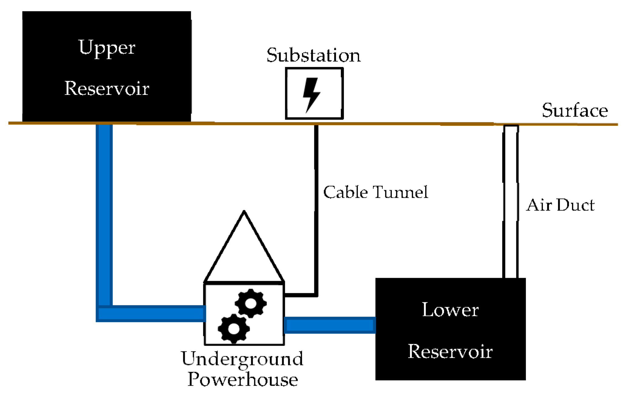
2.2. Underground Pumped Hydroelectric Energy Storage (UPHES)
3. Compressed Air Energy Storage
- Adiabatic or A-CAES: This method processes the heat generated by the compressor to increase the initial temperature of the compressed air, then utilizes cold air during the release of the gas to cool the compressor.
- Diabatic or D-CAES: In the diabatic process, the heat exchange process does not occur as it does in A-CAES. The heat generated by the compressor is released into the atmosphere temporarily to increase the temperature of the gas during the release or expansion process before going to the turbine, a combustion chamber, which usually uses natural gas combustion, is used.
- Isothermal: In this system, constant heat exchange is used to maintain a quasi-constant temperature in the environment, so that when the compression process and air expansion take place in the reservoir, the temperature remains at a stable or constant condition. The drawback of this system is that it is only effective in CAES systems with a low power level [38].
4. Underground Gas Energy Storage
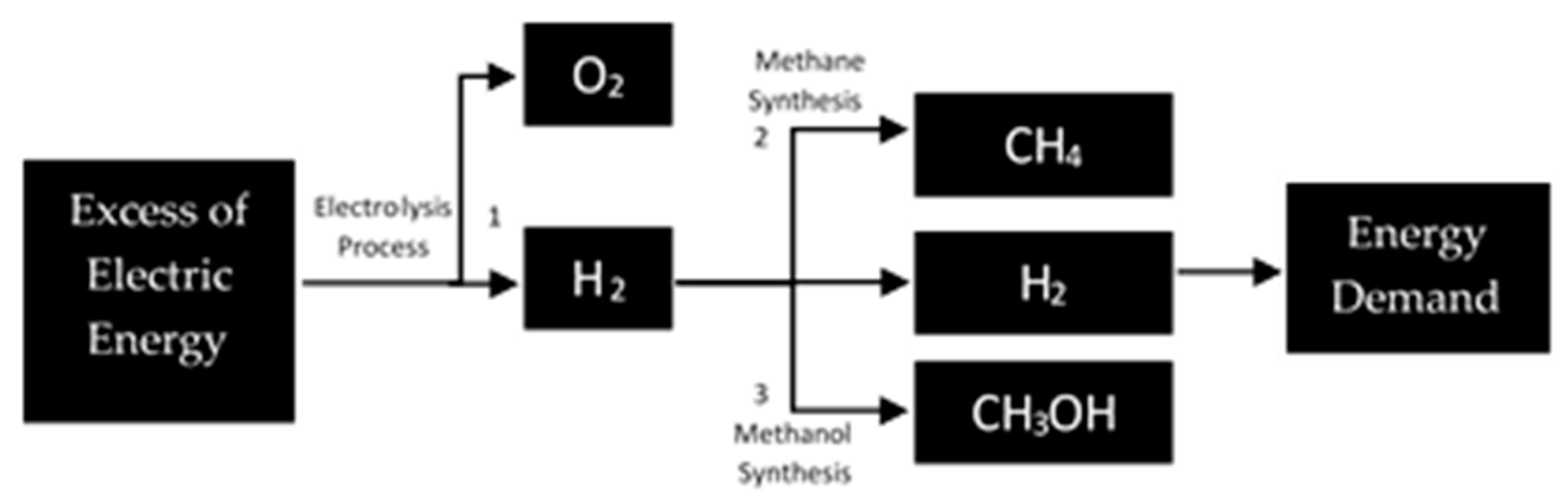
- The second method is a method that is very relevant to the UGS system. In this process, hydrogen (H2) and carbon dioxide (CO2) are processed by a methanation reaction to produce methane gas (CH4) [44]. This methane gas is then injected into the gas distribution network, stored in gas storage, or can be used for all other established natural fuels [44].
- The third method adds hydrogen to the gas produced by the PtG process to increase the quality of the gas through the electrolysis process. In this method, the gas produces impurities such as carbon dioxide, water, hydrogen sulfide, and particulates. Therefore, this material needs to be removed from the gas, because it can cause damage to the storage pipe installation [42].
5. Suspended Weight Energy Storage
6. Comparative Analysis of Electrical Energy Storage
7. Conclusions
Author Contributions
Funding
Institutional Review Board Statement
Informed Consent Statement
Data Availability Statement
Conflicts of Interest
References
- World Energy Outlook 2020—Analysis. 2020. Available online: https://www.iea.org/reports/world-energy-outlook-2020 (accessed on 26 April 2021).
- Renewables: Europe on Track to Reach Its 20% Target by 2020. 2020. Available online: https://ec.europa.eu/commission/presscorner/detail/sl/MEMO_17_163 (accessed on 26 April 2021).
- Energy Policy of Poland until 2040. Available online: https://www.gov.pl/attachment/376a6254-2b6d-4406-a3a5-a0435d18be0f (accessed on 2 April 2021).
- Guney, M.S.; Tepe, Y. Classification and Assessment of Energy Storage Systems. Renew. Sustain. Energy Rev. 2017, 75, 1187–1197. [Google Scholar] [CrossRef]
- Aneke, M.; Wang, M. Energy Storage Technologies and Real-Life Applications—A State of the Art Review. Appl. Energy 2016, 179, 350–377. [Google Scholar] [CrossRef] [Green Version]
- Luo, X.; Wang, J.; Dooner, M.; Clarke, J. Overview of Current Development in Electrical Energy Storage Technologies and the Application Potential in Power System Operation. Appl. Energy 2015, 137, 511–536. [Google Scholar] [CrossRef] [Green Version]
- Hall, P.J.; Bain, E.J. Energy-Storage Technologies and Electricity Generation. Energy Policy 2008, 36, 4352–4355. [Google Scholar] [CrossRef] [Green Version]
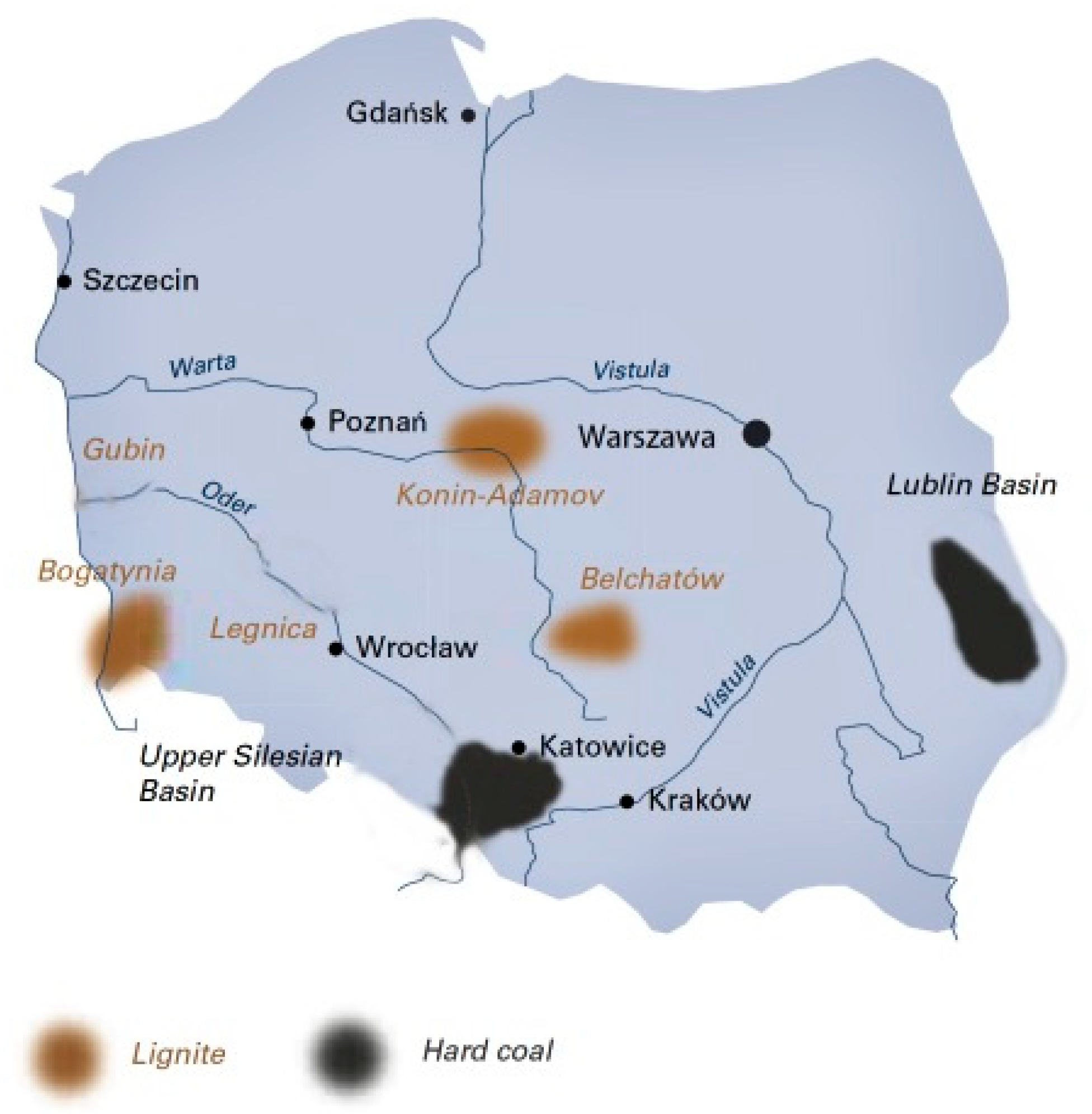
- The Voice of Coal in Europe: Poland. Available online: https://euracoal.eu/info/country-profiles/poland/ (accessed on 26 April 2021).
- Szpor, A.; Ziółkowska, K. The Transformation of the Polish Coal Sector. 2014. Available online: https://www.iisd.org/system/files/publications/transformation-polish-coal-sector.pdf (accessed on 26 April 2021).
- Czapowski, G.; Bukowski, K. Salt Resources in Poland at the Beginning of the 21st Century: Stan Zasobów Soli w Polsce Na Początku XXI Wieku. Geol. Geophys. Environ. 2012, 38, 189. [Google Scholar] [CrossRef] [Green Version]
- Janusz, K.; Ewa, J.; Antoni, C. Changes of Hydrogeological Conditions in the Area of Liquidated Hard Coal Mines in the North-Eastern Part of Upper Silesia Coal Basin (Southern Poland). In Proceedings of the 9th IMWA International Congress, Oviedo, Spain, 20–26 May 2012. [Google Scholar]
- Bukowski, P.; Wagner, J.; Witkowski, A. Use of void space in abandoned mines in the upper silesia Coal Basin (Poland). In Proceedings of the IMWA Symposium 2007, Cagliari, Italy, 27–31 May 2007. [Google Scholar]
- Global Energy Storage Database|Energy Storage Systems. Available online: https://www.sandia.gov/ess-ssl/global-energy-storage-database-home/ (accessed on 26 April 2021).
- Barbour, E.; Wilson, I.A.G.; Radcliffe, J.; Ding, Y.; Li, Y. A Review of Pumped Hydro Energy Storage Development in Significant International Electricity Markets. Renew. Sustain. Energy Rev. 2016, 61, 421–432. [Google Scholar] [CrossRef] [Green Version]
- Hydropower Plants. Available online: https://www.energoprojekt.pl/en/completed-projects/hydro-power-plants (accessed on 26 April 2021).
- Guittet, M.; Capezzali, M.; Gaudard, L.; Romerio, F.; Vuille, F.; Avellan, F. Study of the Drivers and Asset Management of Pumped-Storage Power Plants Historical and Geographical Perspective. Energy 2016, 111, 560–579. [Google Scholar] [CrossRef]
- Rehman, S.; Al-Hadhrami, L.M.; Alam, M. Pumped Hydro Energy Storage System: A Technological Review. Renew. Sustain. Energy Rev. 2015, 44, 586–598. [Google Scholar] [CrossRef]
- Yang, C.-J.; Jackson, R.B. Opportunities and Barriers to Pumped-Hydro Energy Storage in the United States. Renew. Sustain. Energy Rev. 2011, 15, 839–844. [Google Scholar] [CrossRef]
- Berrada, A.; Loudiyi, K. Operation, Sizing, and Economic Evaluation of Storage for Solar and Wind Power Plants. Renew. Sustain. Energy Rev. 2016, 59, 1117–1129. [Google Scholar] [CrossRef]
- Meyer, F. Storing Wind Energy Underground; FIZ Karlsruhe–Leibnz Institute for Information Infrastructure: Eggenstein Leopoldshafen, Germany, 2013. [Google Scholar]
- Winde, F.; Kaiser, F.; Erasmus, E. Exploring the Use of Deep Level Gold Mines in South Africa for Underground Pumped Hydroelectric Energy Storage Schemes. Renew. Sustain. Energy Rev. 2017, 78, 668–682. [Google Scholar] [CrossRef]
- Madlener, R.; Specht, J.M. An Exploratory Economic Analysis of Underground Pumped-Storage Hydro Power Plants in Abandoned Deep Coal Mines. Energies 2020, 13, 5634. [Google Scholar] [CrossRef]
- Matos, C.R.; Carneiro, J.F.; Silva, P.P. Overview of Large-Scale Underground Energy Storage Technologies for Integration of Renewable Energies and Criteria for Reservoir Identification. J. Energy Storage 2019, 21, 241–258. [Google Scholar] [CrossRef]
- San Martín, J.I.; Zamora, I.; San Martín, J.J.; Aperribay, V.; Eguía, P. Energy Storage Technologies for Electric Applications. Renew. Energy Power Qual. J. 2011, 593–598. [Google Scholar] [CrossRef]
- Bodeux, S.; Pujades, E.; Orban, P.; Brouyère, S.; Dassargues, A. Interactions between Groundwater and the Cavity of an Old Slate Mine Used as Lower Reservoir of an UPSH (Underground Pumped Storage Hydroelectricity): A Modelling Approach. Eng. Geol. 2017, 217, 71–80. [Google Scholar] [CrossRef] [Green Version]
- Pujades, E.; Orban, P.; Bodeux, S.; Archambeau, P.; Erpicum, S.; Dassargues, A. Underground Pumped Storage Hydropower Plants Using Open Pit Mines: How Do Groundwater Exchanges Influence the Efficiency? Appl. Energy 2017, 190, 135–146. [Google Scholar] [CrossRef]
- Pujades, E.; Willems, T.; Bodeux, S.; Orban, P.; Dassargues, A. Underground Pumped Storage Hydroelectricity Using Abandoned Works (Deep Mines or Open Pits) and the Impact on Groundwater Flow. Hydrogeol. J. 2016, 24, 1531–1546. [Google Scholar] [CrossRef] [Green Version]
- Menéndez, J.; Loredo, J.; Fernandez, J.M.; Galdo, M. Underground Pumped-Storage Hydro Power Plants with Mine Water in Abandoned Coal Mines. In Proceedings of the 13th IMWA International Congress, Rahua, Finland, 29 July 2017. [Google Scholar]
- Jastrzębska Spółka Węglowa SA-O nas-Zakłady JSW-Budryk-O Zakładzie. Available online: https://www.jsw.pl/o-nas/zaklady/budryk/o-zakladzie (accessed on 24 September 2021).
- Kopalnia Węgla Kamiennego Halemba. Wikipedia, Wolna Encyklopedia. 2021. Available online: https://pl.wikipedia.org/wiki/Kopalnia_W%C4%99gla_Kamiennego_Halemba (accessed on 24 September 2021).
- Ruch Pokój-O firmie-Polska Grupa Górnicza, S.A. Available online: https://korporacja.pgg.pl/o-firmie/oddzialy/2po (accessed on 24 September 2021).
- Wang, J.; Lu, K.; Ma, L.; Wang, J.; Dooner, M.; Miao, S.; Li, J.; Wang, D. Overview of Compressed Air Energy Storage and Technology Development. Energies 2017, 10, 991. [Google Scholar] [CrossRef] [Green Version]
- Lutyński, M. An Overview of Potential Benefits and Limitations of Compressed Air Energy Storage in Abandoned Coal Mines. IOP Conf. Ser. Mater. Sci. Eng. 2017, 268, 012006. [Google Scholar] [CrossRef]
- Energy Storage Association. Compressed Air Energy Storage (CAES). Available online: https://energystorage.org/why-energy-storage/technologies/mechanical-energy-storage/ (accessed on 26 April 2021).
- Layton, L. Compressed Air Energy Storage. Available online: https://pdhonline.com/courses/e365/e365content.pdf (accessed on 26 April 2021).
- He, W.; Luo, X.; Evans, D.; Busby, J.; Garvey, S.; Parkes, D.; Wang, J. Exergy Storage of Compressed Air in Cavern and Cavern Volume Estimation of the Large-Scale Compressed Air Energy Storage System. Appl. Energy 2017, 208, 745–757. [Google Scholar] [CrossRef]
- Succar, S.; Williams, R.H.; Cavallo, A.J.; Christopher, C.K.; Denholm, P.; Dekenberger, D.; Kalinowski, A.; McGill, M.; Socolow, R.; Vann, I. Compressed Air Energy Storage: Theory, Resources, and Applications for Wind Power. Princeton: Princeton Environmental Institute: Princeton, NJ, USA, 2008. Available online: https://acee.princeton.edu/wp-content/uploads/2016/10/SuccarWilliams_PEI_CAES_2008April8.pdf (accessed on 27 April 2021).
- Wang, J.; Ma, L.; Lu, K.; Miao, S.; Wang, D.; Wang, J. Current Research and Development Trend of Compressed Air Energy Storage. Syst. Sci. Control Eng. 2017, 5, 434–448. [Google Scholar] [CrossRef] [Green Version]
- Bader, A.-G.; Beccaletto, L.; Bialkowski, A.; Jaudin, F.; Hladík, V.; Holecek, J.; Van Gessel, S.; Meinke-Hubeny, F.; Wiersma, F. The ESTMAP Project (Energy Storage Mapping and Planning): Focus on the Subsurface Data Collection. 2016. p EGU2016. Available online: https://hal-brgm.archives-ouvertes.fr/hal-01281949 (accessed on 26 August 2021).
- British Geological Survey. An Appraisal of Underground Gas Storage Technologies and Incidents, for the Development of Risk Assessment Methodology. Research Report; 2008. Available online: https://www.hse.gov.uk/research/rrpdf/rr605.pdf (accessed on 2 March 2021).
- Ghaib, K.; Ben-Fares, F.-Z. Power-to-Methane: A State-of-the-Art Review. Renew. Sustain. Energy Rev. 2018, 81, 433–446. [Google Scholar] [CrossRef]
- Power-to-Gas Energy Storage Is Booming. Available online: https://www.betterworldsolutions.eu/power-to-gas-energy-storage-is-booming/ (accessed on 4 April 2021).
- Eberle, U.; Müller, B.; von Helmolt, R. Fuel Cell Electric Vehicles and Hydrogen Infrastructure: Status 2012. Energy Environ. Sci. 2012, 5, 8780. [Google Scholar] [CrossRef]
- Götz, M.; Lefebvre, J.; Mörs, F.; McDaniel Koch, A.; Graf, F.; Bajohr, S.; Reimert, R.; Kolb, T. Renewable Power-to-Gas: A Technological and Economic Review. Renew. Energy 2016, 85, 1371–1390. [Google Scholar] [CrossRef] [Green Version]
- Sarić, M.; Dijkstra, J.W.; Haije, W.G. Economic Perspectives of Power-to-Gas Technologies in Bio-Methane Production. J. CO2 Util. 2017, 20, 81–90. [Google Scholar] [CrossRef] [Green Version]
- Power-to-Gas-Chemical Storage of Excess Power. Available online: https://www.ens.ei.tum.de/en/research/projects/finished-projects/p2g/ (accessed on 26 April 2021).
- Lepszy, S.; Chmielniak, T. Storage System for Electricity Obtained from Wind Power Plants Using Underground Hydrogen Reservoir. J. Power Technol. 2017, 97, 61–68. [Google Scholar]
- Jensen, S.H.; Graves, C.; Mogensen, M.; Wendel, C.; Braun, R.; Hughes, G.; Gao, Z.; Barnett, S.A. Large-Scale Electricity Storage Utilizing Reversible Solid Oxide Cells Combined with Underground Storage of CO2 and CH4. Energy Environ. Sci. 2015, 8, 2471–2479. [Google Scholar] [CrossRef]
- Nunes, P. Potencial de Armazenamento Subterrâneo Em Cavidades Salinas de Gás Natural Em Portugal. Master’s Thesis, IST—Instituto Superior Técnico, Lisboa, Portugal.
- Amid, A.; Mignard, D.; Wilkinson, M. Seasonal Storage of Hydrogen in a Depleted Natural Gas Reservoir. Int. J. Hydrog. Energy 2016, 41, 5549–5558. [Google Scholar] [CrossRef] [Green Version]
- Current State of and Issues Concerning Underground Natural Gas Storage. Available online: https://www.ferc.gov/sites/default/files/2020-05/UndergroundNaturalGasStorageReport.pdf (accessed on 2 April 2021).
- Gimeno-Gutiérrez, M.; Lacal-Arántegui, R. Assessment of the European Potential for Pumped Hydropower Energy Storage Based on Two Existing Reservoirs. Renew. Energy 2015, 75, 856–868. [Google Scholar] [CrossRef]
- Botha, C.D.; Kamper, M.J. Capability Study of Dry Gravity Energy Storage. J. Energy Storage 2019, 23, 159–174. [Google Scholar] [CrossRef]
- Berrada, A.; Loudiyi, K.; Zorkani, I. Dynamic Modeling and Design Considerations for Gravity Energy Storage. J. Clean. Prod. 2017, 159, 336–345. [Google Scholar] [CrossRef]
- Berrada, A.; Loudiyi, K.; Zorkani, I. Sizing and economic analysis of gravity storage. J. Renew. Sustain. Energy. 2017, 8, 1–15. [Google Scholar] [CrossRef]
- Fraenkel, P.; Wright, M. Apparatus and Method for Electrical Energy Storage. 2013. Available online: https://patents.google.com/patent/GB2518125A/en (accessed on 2 June 2021).
- Morstyn, T.; Chilcott, M.; McCulloch, M.D. Gravity Energy Storage with Suspended Weights for Abandoned Mine Shafts. Appl. Energy 2019, 239, 201–206. [Google Scholar] [CrossRef]
- Gravitricity System Offers Lower Cost of Energy Storage. Available online: https://gravitricity.com/gravitricity-offers-lower-cost-of-energy-storage/ (accessed on 2 June 2021).
- Kabiesza, J. Annual Report on the State of Basic Natural and Technical Hazards in Hard Coal Mining. 2018. Available online: https://gig.eu/sites/default/files/raport_roczny_za_%202018_rok.pdf (accessed on 22 September 2021).
- Carnegie, R.; Gotham, D.; Nderitu, D.; Preckel, P.V. Utility Scale Energy Storage Systems. Internal Report of the State Utility Forecasting Group. 2013. Available online: https://www.purdue.edu/discoverypark/energy/assets/pdfs/SUFG/publications/SUFG%20Energy%20Storage%20Report.pdf (accessed on 16 July 2021).
- Mueller, S.C.; Sandner, P.G.; Welpe, I.M. Monitoring Innovation in Electrochemical Energy Storage Technologies: A Patent-Based Approach. Appl. Energy 2015, 137, 537–544. [Google Scholar] [CrossRef] [Green Version]
- IEC White Paper: Electrical Energy Storage. Available online: https://basecamp.iec.ch/download/iec-white-paper-electrical-energy-storage/ (accessed on 26 April 2021).
- Kucukali, S. Finding the Most Suitable Existing Hydropower Reservoirs for the Development of Pumped-Storage Schemes: An Integrated Approach. Renew. Sustain. Energy Rev. 2014, 37, 502–508. [Google Scholar] [CrossRef]
- Menéndez, J.; Loredo, J.; Galdo, M.; Fernández-Oro, J.M. Energy Storage in Underground Coal Mines in NW Spain: Assessment of an Underground Lower Water Reservoir and Preliminary Energy Balance. Renew. Energy 2019, 134, 1381–1391. [Google Scholar] [CrossRef]
- Menéndez, J.; Ordóñez, A.; Álvarez, R.; Loredo, J. Energy from Closed Mines: Underground Energy Storage and Geothermal Applications. Renew. Sustain. Energy Rev. 2019, 108, 498–512. [Google Scholar] [CrossRef]
- Electricity Storage and Renewables:Cost and Markets to 2030. 2017. Available online: https://www.irena.org/-/media/Files/IRENA/Agency/Publication/2017/Oct/IRENA_Electricity_Storage_Costs_2017.pdf (accessed on 2 May 2021).
- Schainker, R. Compressed Air Energy Storage (CAES): Scoping Study for California; Electric Power Research Institute: Palo Alto, CA, USA, 2008. [Google Scholar]
- Müller-Syring, G.; Henel, M.; Koppel, W.; Mlaker, H.; Sterner, M.; Hocher, T. Entwicklung von Modularen Konzepten zur Erzeugung, Speicherung und Einspeisung von Wasserstoff und Methan ins Erdgasnetz. Abschlussbericht DVGW-Projekt G1-07-10: Bonn, Germny, 2013. Available online: https://www.dvgw.de/medien/dvgw/forschung/berichte/g1_07_10.pdf (accessed on 2 June 2021).
- Sterner, M.; Stadler, I. Energiespeicher—Bedarf, Technologien, Integration, 1st ed.; Springer: Berlin, Germany, 2017. [Google Scholar]
- Reytier, M.; Di Iorio, S.; Chatroux, A.; Petitjean, M.; Cren, J.; De Saint Jean, M.; Aicart, J.; Mougin, J. Stack Performances in High Temperature Steam Electrolysis and Co-Electrolysis. Int. J. Hydrog. Energy 2015, 40, 11370–11377. [Google Scholar] [CrossRef]
- Etude Portant sur L’hydrogene et la Methanation Comme Procede de Valorisation de L’electricite exc Edentaire. Available online: https://www.actu-environnement.com/media/pdf/news-25572-power-to-gas-ademe-grtgaz.pdf (accessed on 26 April 2021).
- Beaudin, M.; Zareipour, H.; Schellenberglabe, A.; Rosehart, W. Energy Storage for Mitigating the Variability of Renewable Electricity Sources: An Updated Review. Energy Sustain. Dev. 2010, 14, 302–314. [Google Scholar] [CrossRef]
- Graf, F.; Gotz, M.; Henel, M.; Schaaf, T.; Tichler, R. Techno-Okonomische Studie von Power-to-Gas-Konzepten. Bonn, Germany, 2014. Available online: https://www.dvgw.de/medien/dvgw/forschung/berichte/g3_01_12_tp_b_d.pdf (accessed on 25 June 2021).
- Bath County Pumped Storage Station. Available online: https://www.dominionenergy.com/projects-and-facilities/hydroelectric-power-facilities-and-projects/bath-county-pumped-storage-station (accessed on 2 May 2021).
- Chen, H.; Cong, T.N.; Yang, W.; Tan, C.; Li, Y.; Ding, Y. Progress in Electrical Energy Storage System: A Critical Review. Prog. Nat. Sci. 2009, 19, 291–312. [Google Scholar] [CrossRef]
- Sabihuddin, S.; Kiprakis, A.; Mueller, M. A Numerical and Graphical Review of Energy Storage Technologies. Energies 2014, 8, 172–216. [Google Scholar] [CrossRef]
- Nordling, A.; Englund, R.; Hembjer, A.; Mannberg, A. Energy Storage—Electricity Storage Technologies—IVA’s Electricity Crossroads Project; Royal Swedish Academy of Engineering Sciences: Stockholm, Sweden, 2016. [Google Scholar]
- RWE Power. ADELE—Adiabatic Compressed-Air Energy Storage for Electricity Supply. Available online: https://wecanfigurethisout.org/ENERGY/Web_notes/Round_Pegs/Power_Cycles_and_Energy_Storage_Supporting_Files/ADELE%20%E2%80%93%20Adiabatic%20Compressed-Air%20Energy%20Storage%20for%20Electricity%20Supply.pdf (accessed on 20 May 2021).
- Hydrogenics. Available online: http://www.renewableenergyfocus.com/view/35124/german-wind-park-with-1-mw-hydrogenics-electrolyser-for-power-to-gas-energy-storage/ (accessed on 20 May 2021).
- Ruoso, A.C.; Caetano, N.R.; Rocha, L.A.O. Storage Gravitational Energy for Small Scale Industrial and Residential Applications. Inventions 2019, 4, 64. [Google Scholar] [CrossRef] [Green Version]
- Alvarado Montero, R.; Wortberg, T.; Binias, J.; Niemann, A. Integrated assessment of underground pumped-storage facilities using existing coal mine infrastructure. Sustainable hydraulics in the era of global change. In Proceedings of the 4th IAHR Europe Congress, Liege, Belgium, 27–29 July 2016. [Google Scholar]
- Verzijlbergh, R.; de Vries, L.; Herder, P. Routekaart Energieopslag 2030: Systeemintegratie en Derol van Energieopslag; Report; DNV GL—Energy: Arnhem, The Netherlands, 2015. [Google Scholar]
- Gravity Energy Storage Will Show Its Potential in 2021—IEEE Spectrum. Available online: https://spectrum.ieee.org/energy/batteries-storage/gravity-energy-storage-will-show-its-potential-in-2021 (accessed on 18 July 2021).
- “HyPSTER”: Realising the First EU-Supported Large Scale Green Hydrogen Underground Storage Demonstrator. Available online: http://www.element-energy.co.uk/2021/01/hypster-realising-the-first-eu-supported-large-scale-green-hydrogen-underground-storage-demonstrator/ (accessed on 18 July 2021).
- Scafidi, J.; Wilkinson, M.; Gilfillan, S.M.V.; Heinemann, N.; Haszeldine, R.S. A Quantitative Assessment of the Hydrogen Storage Capacity of the UK Continental Shelf. Int. J. Hydrog. Energy 2021, 46, 8629–8639. [Google Scholar] [CrossRef]
- Corbijn, L.J. Benefits of Underground Pumped Hydro Storage (UPHS) in the Dutch Power System. Master’s Thesis, Utrecht University, Utrecht, The Netherlands.


| No. | Name | Location | Head (m) | Capacity (MW) |
|---|---|---|---|---|
| 1 | Dychow | Lubuskie | 30 | 79.5 |
| 2 | Solina | Solina | 60 | 200.2 |
| 3 | Czorsztyn—Niedzica | Małopolskie | 46.1 | 93 |
| 4 | Porabka-Zar | Slaskie | 439 | 500 |
| 5 | Żarnowiec | Pomorskie | 119.3 | 680 |
| 6 | Żydowo | Wielkopolskie | 81 | 150 |
| Total | 1713.7 |
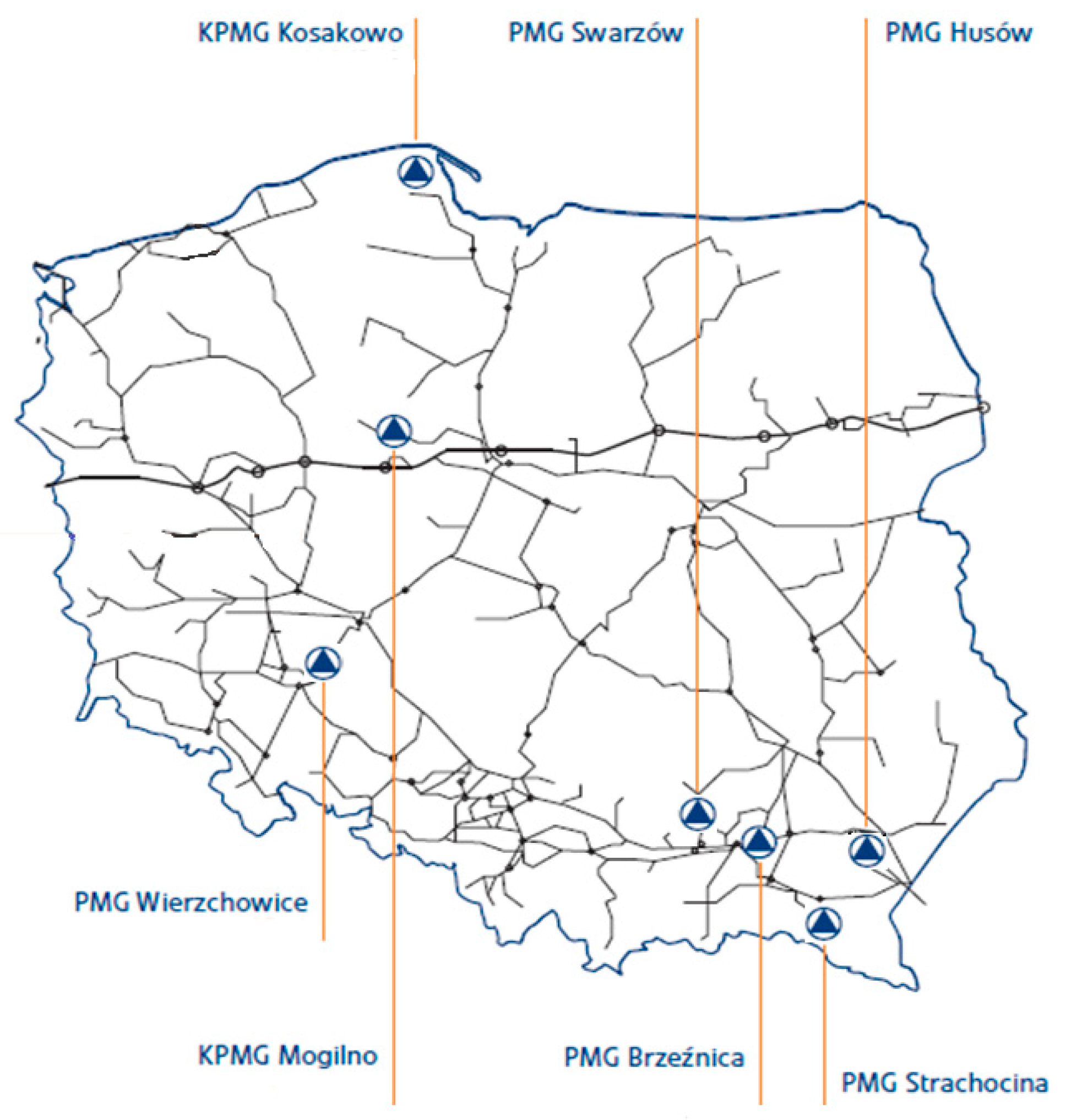
| No. | Gas Storage | Working Capacity | |
|---|---|---|---|
| Million m3 | GWh 1 | ||
| 1 | KPMG Mogilno | 585.4 | 6521.4 |
| 2 | KPMG Kosakowo | 239.4 | 2669.3 |
| 3 | UGS Husów | 500 | 5650 |
| 4 | UGS Strachocina | 360 | 4078.8 |
| 5 | UGS Swarzów | 90 | 1013.4 |
| 6 | UGS Brzeźnica | 100 | 1126 |
| 7 | UGS Wierzchowice | 1300 | 14,729 |
| Sum | 3174.8 | 35,787.9 | |
| Name | Advantages | Disadvantages | Storage Duration |
|---|---|---|---|
| Technical maturity | High cost | ||
| PHES | High energy storage capacity | Low power and energy density | Hours–months |
| Long life cycle | environmental impacts | ||
| No Location constraints | |||
| Technical maturity | Variable efficiency | ||
| Underground CAES | High energy storage capacity | Leakage and Safety issues | Hours–months |
| Location constraints | |||
| High Efficiency | High cost | ||
| UGS, hydrogen | Numerous Sources | Storage Complications | Hours–months |
| High energy storage capacity | Leakage and Safety issues | ||
| Suspended Weight Energy Storage | Low Cost High cyclability | Technical immaturity Low power and energy density | - |
| High power availability |
| Storage Technology | Energy Density (Volumetric) (kWh/m3) | Power Density (kW/m3) | Power Capacity/ Duration | Lifetime (Cycles) | Cycle Efficiency (%) |
|---|---|---|---|---|---|
| PHES | 0.2–2 [61] | 0.1–0.2 [61] | 3003 MW/10 h 18 min [74] | >0.5 × 10⁴ [61] | 65–85 [61] |
| 0.5–1.5 [75] | 0.5–1.5 [75] | 104–3 × 10⁴ [62] | 70–80 [61] | ||
| 0.5–1.3 [76] | 0.01–0.10 [76] | 3003 MW/10 h | 104–6 × 10⁴ [76] | 70–85 [75] | |
| 0.4–1.1 [77] | |||||
| CAES | 2–6 [61] | 0.2–0.6 [61] | 290 MW/2 h [78] | >104 [61] | 41–75 [61] |
| 3–6 [75] | 0.5–2 [75] | 104–3 × 10⁴ [76,65] | 60–90 [76] | ||
| 0.4–20 [76] | 0.04–10 [76] | >104 [61] | |||
| UGS, hydrogen | 500–3000 [74] | 1 MW/27 h [79] | >103 [74] | 20–50 [74] | |
| Suspended Weight Gravity Storage | 1.06–1.6 [55,80] | 3.13 [54] | 40 MW/15 min [60] | 700 [59] | 80–90 [54] |
Publisher’s Note: MDPI stays neutral with regard to jurisdictional claims in published maps and institutional affiliations. |
© 2021 by the authors. Licensee MDPI, Basel, Switzerland. This article is an open access article distributed under the terms and conditions of the Creative Commons Attribution (CC BY) license (https://creativecommons.org/licenses/by/4.0/).
Share and Cite
Saigustia, C.; Robak, S. Review of Potential Energy Storage in Abandoned Mines in Poland. Energies 2021, 14, 6272. https://doi.org/10.3390/en14196272
Saigustia C, Robak S. Review of Potential Energy Storage in Abandoned Mines in Poland. Energies. 2021; 14(19):6272. https://doi.org/10.3390/en14196272
Chicago/Turabian StyleSaigustia, Candra, and Sylwester Robak. 2021. "Review of Potential Energy Storage in Abandoned Mines in Poland" Energies 14, no. 19: 6272. https://doi.org/10.3390/en14196272
APA StyleSaigustia, C., & Robak, S. (2021). Review of Potential Energy Storage in Abandoned Mines in Poland. Energies, 14(19), 6272. https://doi.org/10.3390/en14196272