Article

Influence of the Variability of Compressed Air Temperature on Selected Parameters of the Deformation-Stress State of the Rock Mass Around a CAES Salt Cavern

by
Krzysztof Polański
Faculty of Drilling, Oil and Gas, AGH University of Science and Technology, Mickiewicza 30 Av., 30-059 Kraków, Poland
Energies 2021, 14(19), 6197; https://doi.org/10.3390/en14196197
Submission received: 25 August 2021 / Accepted: 21 September 2021 / Published: 28 September 2021
(This article belongs to the Special Issue Geomechanics for Energy)

Abstract

:
The article presents the results of a numerical simulation of the deformation-stress state in the rock mass around a salt cavern which is a part of a CAES installation (Compressed Air Energy Storage). The model is based on the parameters of the Huntorf power plant installation. The influence of temperature and salt-creep speed on the stability of the storage cavern was determined on the basis of the three different stress criteria and the effort of the rock mass in three points of the cavern at different time intervals. The analysis includes two creep speeds, which represent two different types of salt. The solutions showed that the influence of temperature on the deformation-stress state around the CAES cavern is of importance when considering the stress state at a distance of less than 60 m from the cavern axis (at cavern diameter 30–35 m). With an increase in cavern diameter, it is possible that the impact range will be proportionately larger, but each case requires individual modeling that includes the shape of the cavern and the cavern working cycle.

1. Introduction

The stochastic process of the operation of power plants using renewable energy sources leads to the necessity to develop technologies that allow energy storage when there is no large demand for electricity. Therefore, to increase the use of renewable energy sources in the total energy balance, the most advantageous method turns out to be technologies which use a combination of both conventional fuels and renewable energy sources for the production of electricity.
CAES technology (Compressed Air Energy Storage) uses underground salt caverns to store compressed air. At times of increased demand for electricity in the electrical grid, a gas power plant is started up and the air stored in the cavern is supplied to the gas combustion process in the turbine.
There are two major industrial CAES installations in the world. One is the Huntorf power plant in Germany, which has been working since 1978 and originally had electrical power of 290 MW (currently 310 MW). The other is the McIntosh power plant in the United States (110 MW), operating since 1991.
The advantage of a power plant connected to a CAES system is that all electricity produced in the turbine can be transferred directly to the electrical network and the possibility of storage means that the surplus of energy produced does not have to be transferred to the network at the time of its generation.
When analyzing the work of a salt cavern (the storage part of a CAES installation), it should be noted that it operates in a relatively small pressure range compared to natural gas storage caverns (in the Huntorf power plant, it is in the range 5–7 MPa).
p m a x = g f r a q · h c e m
where:
hcem—depth of cementation (in Huntorf it is around 635 m);
gfraq—safe fracturing gradient, depending on the type of the salt deposit (in practice, it is assumed to be 0.018 MPa/m ± 0.001).
According to the applied criteria, at similar depths as the Huntorf caverns, the pressure of the stored gas could vary from the minimum working pressure of compressors to the maximum pressure (around 11.4 MPa for caverns located at similar depths as Huntorf) [1].
Pressure changes in a CAES storage cavern during operation are very fast; they cause temperature changes in the stored medium and consequently also changes in the temperature of the rock mass around the cavern [2]. Therefore, stress and strain calculations are performed regularly [3,4]. Salt rock has strong rheological properties, the so-called “creep law”, which expresses creep speed as a function of effective stresses, effective deformation, temperature, humidity and structural parameters. Therefore, it should be assumed that the thermodynamic phenomena with the greatest impact on the stability of a CAES cavity are:
  • Cooling of the rock mass during leaching which is caused by the fact that the temperature of the water used for leaching is lower than the temperature of the rock mass;
  • Thermo-hydrodynamic changes in the air injected into the cavern;
  • Heat exchange between the stored medium, the rock mass and the pipes used for exploitation;
  • Heat propagation in the rock mass due to thermal conductivity;
  • Heat convection in the cavern.
However, in practice it is difficult to directly measure the temperature in the cavern during its operation or in the neighboring rock mass (theoretically, it is possible to install sensors inside the cavern, but due to difficulties in connecting to a recording device, this is not done). The phenomena occurring in the cavern can be determined by measuring pressure, temperature and flow capacity in the wellhead.
It is also very difficult to measure the heat transfer coefficients and precisely determine the cavern surface through which heat is exchanged with rock mass. Therefore, as an alternative method of obtaining the necessary information, it is proposed to use a computer model that will properly simulate the necessary parameters during the operation of the salt cavern.
Using the different models of creep law that are discussed in the literature, numerical calculations were performed of the deformation-stress state around a CAES salt cavern, and thermal influence was taken into account [5,6].
However, during laboratory tests of rock salt samples from Polish locations, it was noticed that determining the creep law coefficients for even such a simple law is a relatively difficult issue, even on the basis of tests that are performed for a specific single cavern. It is practically impossible to define a formula with a dozen or so coefficients. Therefore, it is recommended to use a simple Norton formula to describe the salt-creep phenomenon [7].
Therefore, the numerical creep law calculations in the model implemented Norton’s law; these were performed to verify the extent of the influence of temperature changes on the deformation-stress state around the storage cavern. These results were compared [8], which showed that the influence of temperature on the deformation-stress state is important at a distance of less than 50 m from the cavern axis (for a cavern diameter of 30–35 m). At a greater distance, the models begin to converge [8].

2. Thermo-Mechanical Properties of Salt

The location of storage facilities in salt caverns is associated with finding optimal solutions and ensuring long-term stability of the rock mass and the tightness of the storage structure, while maintaining economic profitability. From the geomechanical point of view, the design consists of determining the depth of the cavern foundation and the maximum and minimum working pressure that can be achieved; the geometrical dimensions take the stored medium into account. Design calculations are carried out with the use of specialized computer programs that analyze the state of stresses in the rock mass. Unfortunately, in practice the results of these calculations are different than the actual values, as a result of the discrepancy between the parameters determined in laboratory tests and the actual behavior of the rock mass. The influence of temperature changes the heterogeneity of the salt deposit; the complexity of the equations used are also important [7].

2.1. Thermodynamic Model

The flow and energy of air mass in a CAES installation should be considered a complex process. The application of simple laws of thermodynamics regarding temperature and pressure changes in the cavern allows the behavior of the storage cavern to be predicted with an acceptable level of accuracy. To obtain an analytical solution in this part of the installation (salt cavern) and to determine changes in temperature and pressure, it is suggested to adopt the following assumptions [9,10,11]:
  • For thermodynamic problems, the cavern is considered as one volume (Figure 1);
  • The compressibility of rock salt is very low compared to the compressibility of gas; therefore, it is assumed that the cavern volume is constant throughout the simulation (the change in cavern volume is much smaller than the total volume, therefore its influence on temperature and air pressure is negligible) [12]. When formulating the mass and energy balance equations in the first stage of the analysis, a constant volume V for the cavern is assumed. In the second stage of the analysis, in which the cavity stability is tested, the volumetric convergence is calculated to ensure that the applied thermo-mechanical loads meet the design requirements and stability is maintained;
  • Air flow during injection and withdraw is turbulent, so the air temperature and pressure gradients are very small [13,14]. It is assumed that air temperature, pressure, and air density are uniform throughout the cavern volume;
  • Injection and download air characteristics (temperature, enthalpy, and mass flow rate) are controlled by the CAES installation operator. Therefore, it can be assumed that the air properties are known during the injection and download processes to and from the cavern;
  • Air is considered an ideal gas—this assumption is true for the pressure and temperature inside the CAES storage cavern [10].
Taking into account the above assumptions as well as the general principles of mass and energy balance, a mathematical formulation of the injection process and the air download from the storage cavern is obtained [5].

2.2. Cavern Operating Parameters

When performing thermodynamic calculations for the cavern, it should be assumed that the pressure in the reservoir is equal to the current pressure behind the compressor because it increases during injection due to the constant volume. A constant stream of air mass is maintained by regulating the speed of the compressor. During the calculations, a so-called “air cushion”, i.e., the amount of air remaining in the cavern, is used to ensure the minimum pressure.
However, the fact that the pressure in the cavern before injection is equal to the pressure after expansion (emptying) does not mean that the temperature is also the same [15]. From the thermodynamic point of view, the storage cavern can be considered a reservoir from which there is an outflow through the nozzle due to the stability of the turbine parameters, assuming that an adiabatic process occurs.
It should be clearly emphasized that the purpose of the performed calculations was not to optimize the efficiency of the CAES installation but to maintain the safety of the storage part (the tightness of the cavern and the borehole) and the stability of the cavern during the cyclic operation of the storage facility. Therefore, the simulations focused only on the storage part (cavern). For the numerical calculations, the most extreme working scenario was selected to test the stability of the rock mass around the cavern. Therefore, a situation in which the efficiency of the installation would be reduced was not analyzed; it is expected that—since the stability of the cavern was maintained in the most extreme conditions—lower loading of the CAES installation will have a positive effect on the stability of the rock mass around the cavern.

2.2.1. Balance of Mass and Energy in the Cavern for Steady-State Conditions

Assuming a constant cavern volume V, the equation of the mass flow balance during injection and download takes the form:
V ρ ˙ a i r = m ˙ i n j m ˙ d o w
where:
V —cavern volume (m3);
ρ ˙ a i r —air density change in the cavern (kg/m3 s);
m ˙ i n j , m ˙ d o w —mass flow during injection/download (kg/s).
The mass flow rates depend on the technical requirements of the installation (e.g., maximum compressor capacity or maximum air supply to the gas turbine) as well as the energy demand from the electrical grid.
The operator of the CAES installation can adjust the properties of the air inside the cavern to the desired range by controlling only these two factors.
Thus, the energy balance for the cavern takes the form:
V ( ρ ˙ a i r u + ρ a i r u ˙ ) = m ˙ i n j h i n j m ˙ d o w h d o w U A c a v ( T c a v T r o c k )
where:
ρ a i r —air density in the cavern (kg/m3);
u—internal energy (J);
h d o w , h i n j —air enthalpy during download and injection (kJ/kg);
U—heat transfer coefficient between the cavern wall and the rock mass ( W m 2 · K ) ;
Acav—the area between the cavern and the rock mass (m2);
Tcav, Trock—air temperature in the cavern and rock mass temperature (K).
The last term on the right side of Equation (2) represents the heat exchange between the cavern and the salt rock mass.
If air is considered an ideal gas, the following equations can be used to calculate the pair pressure, internal energy u, and air enthalpy h.
p a i r = ρ a i r R T c a v
u = h p a i r ρ a i r
h ˙ = c a i r T ˙ c a v
where:
cair—specific heat of air ( J mol · K ) ;
R—universal gas constant 8.3143 ( J mol · K ) .
By replacing the above-mentioned relationships (4, 5, 6) with the physical quantities in Equation (3) and using the mass balance Equation (2), a relationship is obtained that allows the change in air temperature to be described. Knowing the properties of air during the injection and consumption of compressed air, the equation below can be solved for any moment of operation. For this, the default finite difference scheme is used to solve the problem.
ρ a i r ( c a i r R ) T ˙ c a v + m ˙ i n j c a i r V ( T c a v T i n j ) + R T c a v V ( m ˙ d o w m ˙ i n j ) + U A c a v V ( T c a v T r o c k ) = 0
where:
T i n j —temperature of the injected air (K).
The heat transfer coefficient U and the Acav area are values that cannot be easily determined [9,10], therefore the relationship U A c V should be replaced by the effective heat transfer coefficient [10], which is a function of the air mass flow rate during injection and the downloading of compressed air from the cavern:
U e f = a 1 + a 2 | m ˙ d o w m ˙ i n j | a 3
where:
a1, a2, a3—parameters obtained during the calibration model with data from in-situ measurements [5].

2.2.2. PVT Equation for the State of Gas in a Cavern

In classical numerical models, air is usually treated as an ideal gas (Clapeyron equation):
pv = n R T
where:
p—pressure (MPa);
T—temperature (K);
v—molar volume ( m 3 mol ) ;
n—number of moles of gas (-).
The general equation of state for the real gas is used in the calculations:
pv = Z RT
where:
Z—compressibility factor (-).
The Z coefficient of compressibility is a function of the gas state in question, depending on the composition, temperature, and pressure. The model uses the Redlich–Kwong and Peng–Robinson real gas equations of state as well as other simplified PVT correlations.

2.2.3. Heat Exchange between Cavern and Rock Mass (Macroscopic Balance)

The isochoric cavern model (with the assumption that the variability of the stored air volume can be limited) can be described by the equation:
( d P d t ) V = 1 V [ κ R T i n j m ˙ i n j κ R T m ˙ d o w + ( κ 1 ) U A c a v ( T A c a v T ) ]
where:
κ —air adiabatic exponent (-);
T A c a v —temperature on the surface Acav (in the rock mass) (K).
The dynamic air temperature model can be described by the equation:
( d T d t ) V = U A c a v ( T z T ) + m ˙ i n j C r o c k ( T i n j T ) + V ( d P d t ) V m C r o c k
where:
m—air mass (kg);
C r o c k —specific heat of the rock mass ( J kg · K ) [16].
However, the heat exchange between the compressed air inside the cavern and the rock mass can be described by the equation:
Z λ r o c k T r o c k · n d S = Ω α ( T c a v T r o c k ) d S
where:
α—heat transfer coefficient ( W m 2 · K ) ;
λ r o c k —thermal conductivity coefficient in the rock mass ( W m · K ) ;
dS—surface element;
n—a unit vector normal (which points outward) to the surface of a cavern or gas-filled well (-);
Ω—any fragment of the surface of the reservoir (-).
The shape of the salt cavern cannot be described as an ideal sphere or cylinder because its side surface, due to its irregular shape, is much larger than that of a sphere with an analogous volume, hence the theoretical coefficient α should be treated as an approximation. In practice, inaccurate knowledge of the heat exchange has a relatively small effect on the cavern temperature. When using high coefficients (above 20 ( W m 2 · K ) ), the heat inflow from the salt rock is limited by its thermal conductivity.

2.2.4. Temperature Changes in the Salt Rock Mass—Thermal Conductivity

Thermal conductivity in the rock mass is realized by the equation that compares the heat change in a given volume to the heat conduction balance through the side surface of this volume:
t Ω ρ rock C rock T rock d V = Γ λ r o c k T r o c k · n d S
where:
ρ rock —rock mass density (kg/m3);
T—the surface of Ω element (m2).
This equation can determine the temperature distribution in the area on the edge of which the temperature or its gradient is known. Considering the rock mass in the vicinity of the cavern, the range of the model is so large that that the thermodynamic changes taking place in the cavern do not affect the conditions on the edge of the model. It can be assumed that the temperature at the edge of the considered model (in the rock mass at a great distance from the cavern side) does not depend on time but only on depth, according to the geothermal degree:
T r o c k = c o n s t ( h )
where:
h—depth below the ground surface (m) [17].

2.3. The Constitutive Equation of Rock Salt

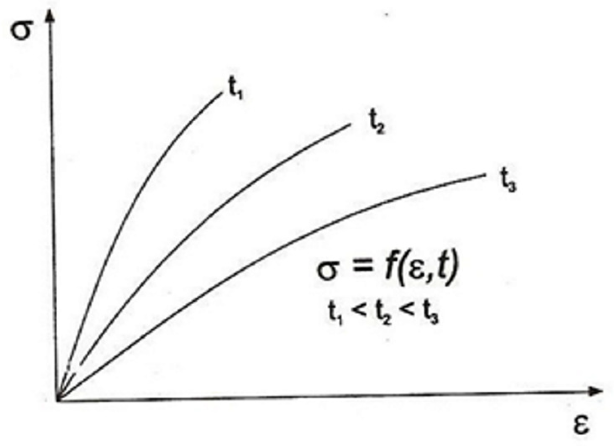
A characteristic feature of rheological media, including rock salt, is the influence of loading time on the amount of deformation (Figure 2). When salt samples are compressed, an increase in strain is observed at a given stress level as a function of the loading time.
Temperature, humidity, and grain size are also additional factors which may affect the deformation of the tested salt samples. Due to the rheological properties of the salt, even with constant loading of the samples, the deformation increases with time [7].
An important phenomenon in laboratory tests of salt loading is the so-called creep and salt relaxation (a decrease in stresses in a state of deformation that is constant over time).
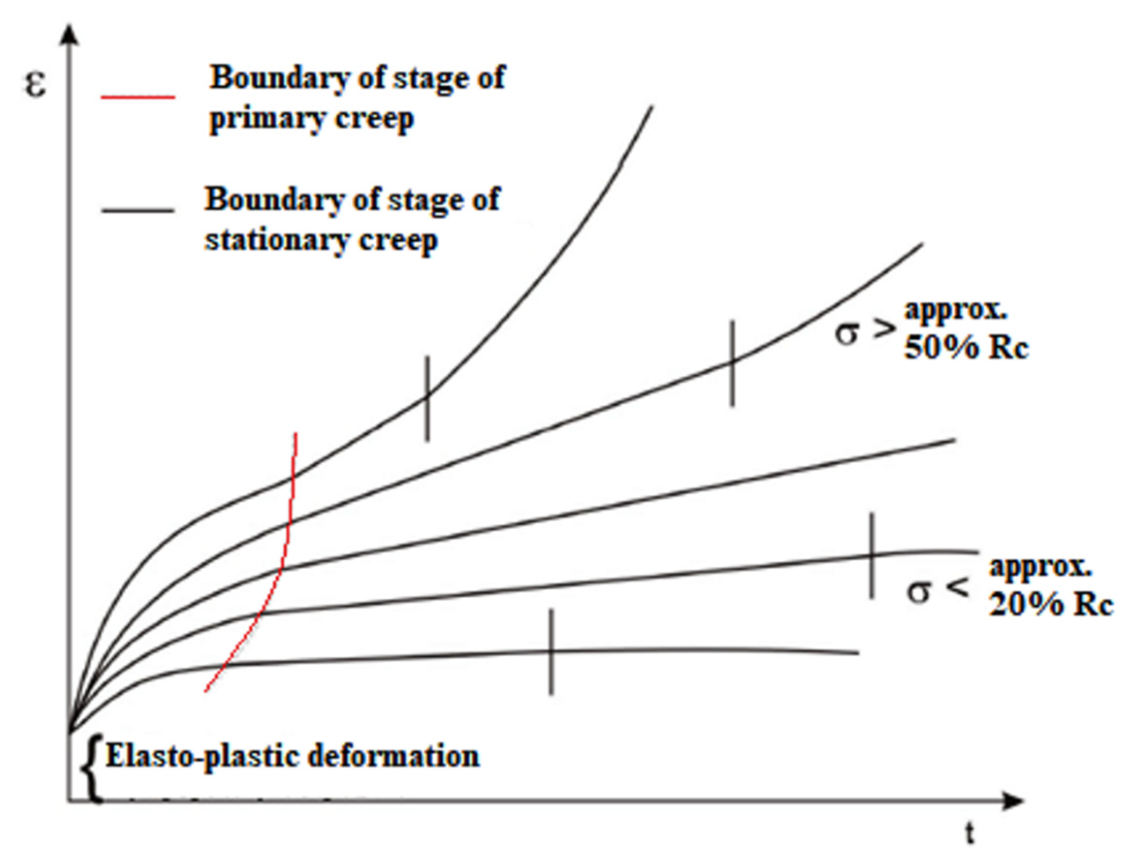
In the description of the creep phenomenon, four phases should be distinguished (Figure 3):
  • The initial deformation phase occurs so quickly that time is usually omitted in its description;
  • Primary creep, when creep speed decreases;
  • Stationary creep, characterized by a constant increase in strain over time. This phase has the greatest impact on the strain-stress state of the rock mass around the cavern;
  • Final phase. Under the influence of stresses, creep accelerates rapidly, which leads to material destruction [7].
The creep speed in elastic-viscous media depends not only on their deformation-stress state but above all on the state of knowledge about them; this causes great difficulties in describing the properties of salt. In practice, a large number of simplifications are used [7].
To describe the properties of salt, it is assumed that it is an isotropic medium, i.e., the properties of the medium are independent of the direction in which they are measured. In addition, it is assumed that the change in the deformation state is a function of the current independent variables and depends on stress, strain, temperature and time [7].
Another important assumption is the application of the superposition principle for deformation; this principle determines the total increase in deformation as the sum of plastic, elastic and viscous deformations. The description of elastic deformation is based on Hooke’s law, and the influence of temperature is also considered. Although the influence of plastic deformations on the rock mass in the vicinity of the storage cavern is smaller than that of elastic deformation, the theory of their description is essential because theories of plasticity are built on this basis. The description of plastic deformation includes the theory of plastic flow and the theory of plasticity. Viscous deformations require the assumption of zero creep dilatancy [7].
The rheological properties of the medium are represented by the constitutive equation given in the form of two equations. The first describes the change in volume and relates the stress and strain axioms. The second is the deviator equation that describes the law of change of form [7].
F ( P σ { D σ } ) , ( Q ε { D ε } ) = 0
where:
Pσ, Qε—differential operators;
Dσ—stress deviator (MPa);
Dε—deformation deviator (‰).
In special cases, the deviator equation may assume a linear form with constant coefficients. Then, the components of the deviators of both stresses and strains are related by the following relationship [7]:
k = 0 n a k k s i j t k = i = 1 n b k k e i j t k
where:
ak, bk—constant coefficients;
σm—mean stress (MPa);
εm—mean deformation (‰);
δij—Kronecker’s delta (-).
s i j = σ i j σ m · δ i j
e i j = ε i j ε m · δ i j
σ m = 1 3 ( σ 11 + σ 22 + σ 33 )
ε m = 1 3 ( ε 11 + ε 22 + ε 33 )
δ i j = { 1   f o r   i = j 0   f o r   i 1 } .
Various models are used to describe the properties of a rheological medium, e.g., Kelvin, Maxwell, Poynting–Thomson, and Prager. However, the rheological model of rock salt is actually much more complicated. The coefficients of the constitutive equation are not constant parameters as they depend on the stresses and side factors. The complexity of the models used to describe salt is mainly from taking into account various types of salt-creep deformations. The final form of the rheological equation is primarily determined by the manner in which the properties of a complex medium are presented as a set of properties of simple media [7].
As was mentioned in the introduction, during the laboratory tests of rock salts it was noticed that determining the creep law coefficients for even such a simple law is a relatively difficult issue, therefore it is recommended to use a simple Norton’s formula to describe the salt-creep phenomenon [7].

2.4. Cavern Stability Parameters

Geomechanical problems in terms of the stability of the storage cavern as a result of its exploitation should be considered in five categories [18]:

2.4.1. Local Stability of the Cavern

There are several criteria to be met by the cavern in order not to damage the salt rock on the side walls and the ceiling:
  • Lack of tensile stresses. This criterion results from the very low tear strength of the salt, which means that in the evaluation of the stress state it is assumed to be zero. If this criterion is met, an appropriate vault is created during the leaching of the cavern.
  • Long-term durability is not exceeded. This is one of the most discussed criteria in geomechanics. In the case of rock salt, it is unacceptable for the rock mass to enter the third phase of creep because this leads to rapid destruction. In order to determine the permissible stress state, strength hypotheses and rock mass effort are introduced as these determine the value of the analyzed stress state in relation to the short-term strength. The allowable values of the effort are determined subjectively depending on the required level of security.
  • The permissible deformations are not exceeded. Taking into account the ambiguity of the stress and deformation states and the variable pressure inside the working storage cavern, it is necessary to determine the permissible effective deformation state. This criterion determines the allowable increase in effective deformation during pressure reduction and at minimum pressure, as well as the allowable rate of effective deformations.

2.4.2. Global Cavern Stability

The assessment of this criterion consists of examining the extent of the impact of the cavern on the rock mass. This criterion is determined on the basis of the range of stresses and effective deformations as well as the effort of the rock mass, assuming that the range of significant changes in these quantities determines the extent of the impact of the cavern.
It should be noted that the theoretical extent of the impact of the storage cavern on the rock mass depends primarily on the constitutive equation adopted for the description of the rock mass. With high rheological properties, the range should be greater.

2.4.3. The Tightness of the Cavern

The tightness criterion is related to the maximum storage pressure in the cavern and is determined on the basis of microfracturing tests carried out in the well during its drilling. On the basis of these tests, the so-called “resting pressure of fracturing”, which is established after fracturing the rock mass and is close to the primary pressure in the rock mass, increases proportionally to the depth. The proportionality factor is called the microfracture gradient.
The stress distribution around the cavern when the stored medium (air) is at high pressure differs from the primary pressure of the rock mass. The migration of the stored medium is therefore possible at a pressure lower than that which results from the microfracture gradient. When determining the maximum storage pressure, an appropriate safety factor is adopted.
The issue of the tightness of the cavern is also related to its maximum allowable height. If it is too high, it is not possible to empty the brine from the cavern due to cracking of the rock mass in the ceiling. The permissible maximum height of the cavern is determined by the formula [7]:
H c a v H c e m · ( ϕ s γ b r i n e + x 1 )
where:
Hcav—active height of the cavern, including the “neck”;
Hcem—cementation depth (m);
ϕs—resting microfracture gradient (MPa/m);
x—brine flow resistance per 1 m of pipe (-);
γbrine—specific gravity of brine (kg/m3).
This condition is essential in the case of shallow-set storage caverns.

2.4.4. Cavern Capacity Changes during Storage Operations

The loss of the cavern’s active capacity due to convergence is one of the most important issues that arise during the exploitation of storage caverns in rock salt deposits. This phenomenon is inevitable, and its intensity depends on the depth of the foundation, rheological properties, as well as the operating pressure, in particular the minimum pressure.
At constant pressure, the rate of convergence stabilizes and is a value that can be approximated by the formula [1]:
k ( p , T , η ) = V t = A 1 ( p ( h center ) p σ 0 ) m 1 e Q 1 RT ( 1 + B 1 η )
where:
p ( h center ) —primary rock mass pressure at the depth of the cavern center (MPa);
A1, m1, Q1, B1—coefficients;
η—cavern slenderness (-);
σ 0 = 1 MPa.
Since the pressure in the cavern is not constant during the operation of the storage installation, the rate of convergence changes over time. Generally, when describing the storage operation scenario, it can be divided into four stages, and it can be assumed that:
  • The cavern remains at pressure pmin for duration ∆tmin;
  • The cavern is filled to pressure pmax for duration ∆tinj;
  • The cavern remains filled to pressure pmax for duration ∆tmax;
  • The cavern is emptied to pressure pmin for duration ∆tdow.
Then, the average annual rate of convergence can be described by the formula [1]:
k ¯ = k ( p min ) Δ t min + k ( p max ) Δ t max 365 + k ( p min ) ( p p min ) k ( p max ) ( p p max ) ( m 1 + 1 ) ( p max p min ) · ( Δ t inj + Δ t dow ) 365

2.4.5. Protection of the Site Surface

Surface settlement in the case of storage caverns is a marginal issue due to the large foundation depths of the caverns and the distance between them. Despite this, regular leveling measurements are carried out; however, as practice shows, the possible land subsidence is much smaller than in the case of the classic exploitation of rock salt using the borehole method [1,18].

3. Assumptions for the Assessment of the Influence of Temperature Variability on the Deformation-Stress State of Salt Rock

Based on the parameters of the original installation in Huntorf, certain design assumptions were made as a result of technical and economic conditions that are mainly related to the strength of production pipes, casing pipes and cementation under significant temperature fluctuations. The parameters of the Huntorf power plant indicate that the well productivity exceeds 1 million m3/h, which requires the use of 24′′ diameter production pipes. An increase in the depth of the cavern foundations would significantly affect the cost of piping and compressors and would increase the flow resistance; therefore, it would reduce the overall efficiency of the power plant.

3.1. Analysis of the Injection and Download Cycles of the Cavern

Taking as a reference the parameters of the Huntorf power plant [2], which has a power of 290 MW, a cavern volume of 310,000 m3, and which can be emptied in 2 h, the active volume of cavern V for generating power P should be [4]:
V = 310 2 · 290 P · t
where:
V—volume in thousand cubic meters;
t—operating time in hours;
P—power in MW.
The number of caverns n to be leached to reach the required volume V:
n = V m i n i m u m ( V 0 1 , V 0 2 )
This depends on two factors:
the deposit thickness, which limits the cavern volume [4]:
V 0 1 = 2827.4 · ( M 85 )
where M is the thickness of the salt deposit;
limitations resulting from the possibility of emptying the cavern in the required time:
V 0 2 = 170 · t 2
The number of caverns, n, is determined by the smaller of these values.
Based on the above equations, it is possible to estimate the number of caverns that should be made in order to obtain the required power in a deposit of a certain thickness. Assuming the thickness of the rock salt deposit is approx. 200 m, two caverns (cavern height of 150 m) should be leached to achieve a capacity similar to that of the Huntorf power plant (300 MW) and to deliver energy for 2–3 h. However, if the energy delivery time were extended to 8 h, the number of caverns needed would increase to 4.

3.2. Preferred Range of Operating Pressure

The range of pressures at which a storage cavern operates depends primarily on the depth of its foundation, the geological structure of the deposit, and the stored medium, as well as the operating scenario. For this reason, the parameters of the CAES installation in Huntorf were adopted for numerical simulations. The maximum operating pressure will be close to the maximum operating pressure of the system, i.e., 66 bar. The minimum pressure (the pressure to which the caverns in the Huntorf are emptied) will be 46 bar. On this basis, the operating pressure amplitude in the simulated cavern was 20 bar.

3.3. Temperature Variation Range

For the simulation it was decided to assume that the volume of the cavern was close to the volume of the existing caverns in Huntorf, i.e., 150,000 m3: the cavern ceiling was at a depth of 650 m; the bottom of the cavern was at a depth of 800 m. The assumed working scenario was continuous operation of the CAES storage facility. The following parameters were adopted for the simulation:
  • Daily cyclic emptying and filling—1 daily cycle consists of two hours of emptying the cavern (download); 6 h of resting the cavern at the minimum pressure, 8 h of filling (injection); and 8 h of resting the cavern at the maximum pressure.
  • With these assumptions, a thermodynamic simulation of CAES cavern operation was carried out. On this basis, the temperature distribution in the cavern was obtained. Then, the temperature distribution in the cavern was included in the further geomechanical calculations using a modified version of the GEOSOLK program, which considers the thermo-mechanical effects, including the temperature distribution around the storage cavern.
  • For proper simulation in the GEOSOLK program, it was assumed that after the leaching process was completed, the cooling of the rock mass would stabilize the temperature in the cavern at 36.0 °C.
  • For the thermodynamic simulations, the minimum temperature in the cavern (in the first emptying to 46 bar) was 12.28 °C. After 365 daily operating cycles, it dropped to the minimum value: 11.19 °C.
  • The maximum temperature in the cavern after filling to the maximum pressure was 41.54 °C at the beginning of the simulation (after the first filling); it stabilized at 40.23 °C after filling and the simulation was complete after 365 daily work cycles.
The preliminary calculations showed that the maximum range of temperature changes (the difference between the temperature in the cavern after emptying and the temperature after filling) did not exceed 30 °C.

4. Numerical Model of CAES Salt Cavern Operation

The aim of the simulations was to determine the impact of changes in the temperature of the stored compressed air on the strain-stress state of the rock mass directly in its vicinity. The simulations included the range of temperature changes and load changes that corresponds to the operated CAES cavern. The temperature distribution around the cavern during operation was also made.
Numerical simulations of the stress-strain state of the rock mass during the exploitation of the CAES cavern were performed using the GEOSOLK software. Initially, the calculations were performed with the assumption that the original temperature in the salt deposit did not change over time. Then, the calculations were performed with the assumption that the temperature did change over time, and the temperature distribution in the rock mass was caused by the variable air temperature in the cavern and the conditions on the edges of the model:
(1)
Constant primary temperature on the vertical edge of the model;
(2)
The heat flux resulting from the geothermal gradient on the horizontal edge.
To compare the results of both simulations, the influence of temperature changes on the stress-strain state of the rock mass was assessed.
The simulations were performed for two sets of parameter values of the adopted “creep law”. The scenario of a cyclical CAES cavern operating for 365 days was analyzed.
During the assessment of cavern stability, the stresses and effective deformations were used [8]. An analysis of the distribution of the rock mass effort around the cavern in the selected model elements at the edge of the cavern was also carried out.
Since no single simple criterion has been created so far to define the permissible stress and strain limit values in the cavern vicinity, several criteria describing the effort of the rock mass in the vicinity of the cavern are instead used for this. In this research, three criteria were used (described in Section 5) [4].
The effort values obtained according to these criteria were compared with the values obtained using the formulas developed by Lux, Hou and Düsterloh [18].
Figure 4 shows a diagram of the working CAES cavern modeling procedure, taking into account the changes in air pressure and temperature during download from and injection into the storage. The models and criteria described below were adopted for the thermo-mechanical analysis of the deformation-stress state.

4.1. Strength Criteria Adopted for Salt

The strength criteria commonly used for rock salts occurring in Poland were adopted for the numerical calculations. The GEOSOLK software’s strength criteria file contains seven parameters. The values of these parameters were as follows:
Rc = 20.6 MPa—uniaxial compressive strength of rock salt;
ALFA = 0.025—ratio of uniaxial tearing and compressive strength; parameter of Burzyński’s stress hypothesis;
AP = 17.55—power factor, stress strength criterion (for stress in MPa);
BP = 0.692—exponent in the power stress strength criterion;
AE = 21.82—power factor, deformation strength criterion (at stresses in MPa);
BE = 0.74—exponent in the power strain strength criterion;
E0 = 30.0—limit deformation (destructive) in the power strain criterion.

4.2. The Condition of Viscoelasticity–the Creep Law

In the adopted numerical model, Norton’s creep law, taking into account elastic strains and viscous strains, was used to describe the viscoelasticity condition [7].
d ε = d ε e l + d ε ν
where:
d ε —total increase of strains;
d ε e l —increase of elastic strains;
d ε ν —increase of viscous strains.
To compare salts with different rheological properties, the coefficients that describe the viscous strains part of the equation were modified in the numerical model.
Additionally, the adopted assumption of deformation superposition allows for a separate description of each type of deformation. The description of elastic strains is based on Hooke’s law and the assumption of salt isotropy, so we can write [7]:
ε i j e l = 1 + ν E σ i j 3 ν E σ m δ i j
ε m = 1 K σ m
where:
ε i j e l —components of the strain tensor;
σ i j —components of the stress tensor;
δ i j = { 1   f o r   i = j 0   f o r   i 1 }
E—Young’s modulus;
ν—Poisson’s ratio.
Values for the salt used in the calculations: E = 8 GPa, ν = 0.2.
The speed of the creep tensor components is expressed as [7]:
d ε i j ν d t = 3 2 · d ε e f ν d t · s i j σ e f
where:
σ e f = 2 2 ( σ 11 σ 22 ) 2 + ( σ 22 σ 33 ) 2 + ( σ 33 σ 11 ) 2 + 6 ( σ 12 2 + σ 23 2 + σ 31 2 )
ε e f = 2 3 ( ε 11 ε 22 ) 2 + ( ε 22 ε 33 ) 2 + ( ε 33 ε 11 ) 2 + 3 2 ( ε 12 2 + ε 23 2 + ε 31 2 )
However, the unknown in the above equation is the speed of effective deformation related to the creep d ε e f ν d t . The creep law is a formula that defines the speed of effective creep strains as a function of effective stresses, effective strains, time and temperature.
Based on the results of laboratory tests and literature studies, it was decided to use Norton’s creep law while creating the numerical models [7].
d ε ef dt = Ae Q RT σ ef n
where:
Q—activation energy (J/mol);
R—universal gas constant ( J mol · K ) ;
T—temperature (K);
A, n—constant coefficients.
To be able to compare the values obtained in the two models that depend on the salt-creep speeds, two values of the A coefficient were adopted so that the laws used for calculations significantly differed in terms of the creep speed.
For the calculations, the Q/R ratio = 6500 K was assumed, which means that at 50 °C the salt-creep rate will be almost eight times faster than at 20 °C. For this value of the Q/R coefficient, two values of the power coefficient were adopted, n = 4 and n = 5, because this range probably includes the actual value of this coefficient for the salt rock mass. The values of Norton’s creep law coefficients adopted in the models are summarized in Table 1.

4.3. Thermal Properties of Salt

It was assumed that the primary temperature of the salt rock mass changes linearly [19]:
T = α r o c k · H + β
where:
αrock—temperature gradient;
β—constant ratio;
H—depth (below ground level).
The value of the temperature gradient varies according to the salt structure under consideration; therefore, for the purposes of computer simulations, the average values of the parameters related to the thermal properties of salts are summarized in Table 2.
On the basis of the adopted temperature gradient, it was determined that the range of temperature changes in the rock mass in the interval 0–2000 m was 15–75 °C.

4.4. The Adopted Calculation Scenario and Model Parameters

The scenario used for the simulations was based on a working installation using CAES (Compressed Air Energy Storage) technology for energy storage in compressed air [4,20].
Due to the fact that there are very rapid pressure changes in an operating CAES installation (pressure drop by 2 MPa in two hours), one can expect equally rapid changes in temperature inside the cavern that should be taken into account in the calculations [2,21].
The adopted calculation scenario consisted of 365 cycles of cavern daily operation. One cycle includes two hours of downloading the compressed air from the cavern; 6 h of pause (the cavern stays under the minimum pressure); 8 h of injection of compressed air into the cavern; and 8 h of pause at maximum pressure. In the numerical calculations, the maximum pressure in the cavern is 6.6 MPa when the cavern is full, and the minimum pressure is 4.6 MPa when the cavern is empty [3,22,23,24].
The selection of the most representative points at which the effort was assessed was based on the representativeness assessment performed in [1], which is based on analysis of the correlation of effective stress values at selected points. The compared solution variants showed that the relevant results are strongly correlated [1].
The convergence values calculated with GEOSOLK software in the previous simulations were verified with the calculations carried out in FLAC 2D software [1]. The performed calculations showed a high similarity of obtained results.
To determine the extent of the impact of temperature changes in the cavern on the rock mass, the preliminary studies were carried out for two models [8]:
1—With a constant distribution of rock mass around the storage cavern;
2—Taking into account the impact of changes in the temperature of the rock mass around the storage cavern.
The model grid consisted of 660 elements. The horizontal range of the cavern (measured from the cavern center) was 250 m, including 17.84 m in the cavern radius. The vertical range (measured from the cavern center) was also 250 m [8].
The obtained results showed the greatest differences directly on the cavern wall and in its very close vicinity. On the basis of the obtained results, it was concluded that the influence of temperature on the deformation-stress case in the vicinity of CAES caverns is important when considering the stress state at a distance of less than 50 m from the axis of the storage cavity (when considering storage caverns with diameters of 30–35 m) [8].
Therefore, the same cavern model was used in the calculations (radius 17.84 m and height 150 m) for the 650–800 m interval below ground level, which resulted in a cavern volume close to 150,000 m3. A pipe with an external diameter of 21′′ (internal diameter 20′′) was adopted for the cavern exploitation. However, compared to the preliminary model [8], the number of mesh elements was increased to 996. The number of elements was optimized so as to obtain satisfactory computer operation because no large differences in the obtained results were noticed in the simulations performed for other meshes (increasing the number of elements in the mesh did not cause large differences in the obtained results).
Table 3, Table 4 and Table 5 summarize the most important parameters of the cavern model on which the simulations were carried out.

4.5. The Influence of Creep Law on the Deformation-Stress State in the Rock Mass Around the CAES Cavern

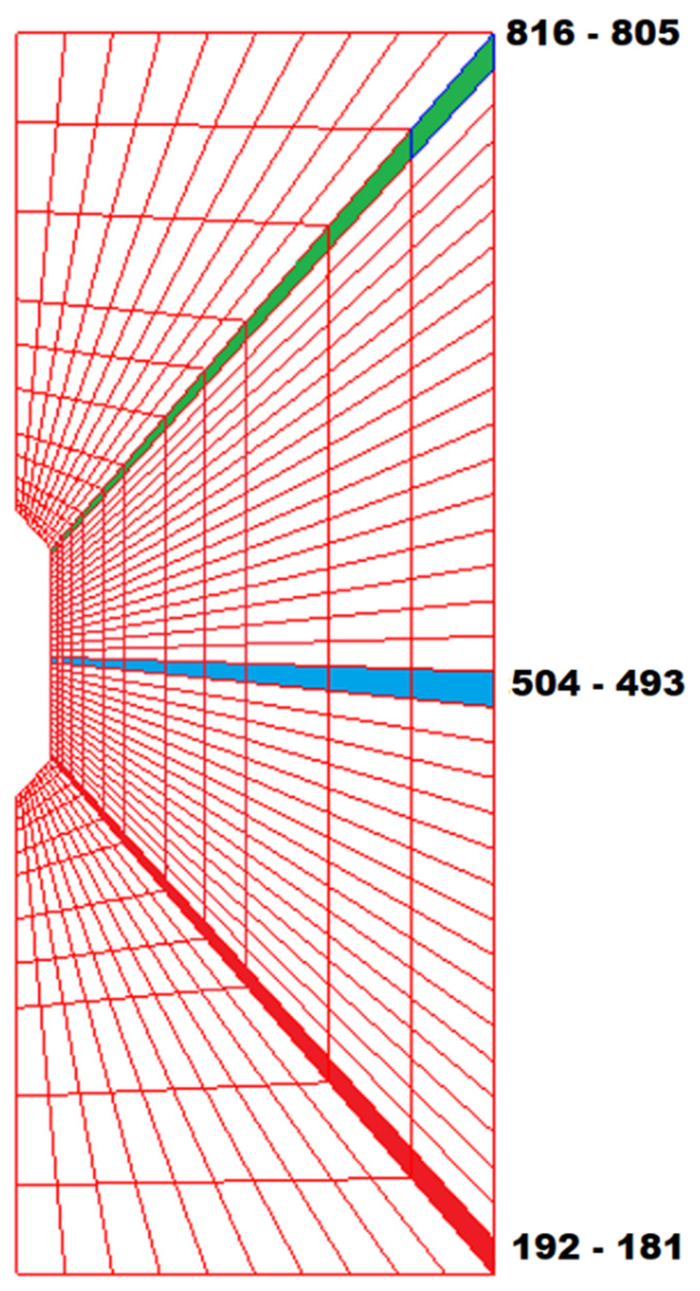
Figure 5 shows the CAES cavern mesh, with selected elements marked at points on the ceiling, side wall and bottom (measured from the wall of the cavern into the rock mass). It should be noted that the shape of the cavern used for the simulation is different in the upper wall and in the lower wall; this is dictated by the SMRI (Solution Mining Research Institute) guidelines regarding the relationship between the shape of the dome and the diameter and height of the cavern.
The results presented below take into account the calculations for the two models: fast-(FCL) and slow-creep law (SCL), taking into account the impact of changes in the temperature of the rock mass around the storage cavern.
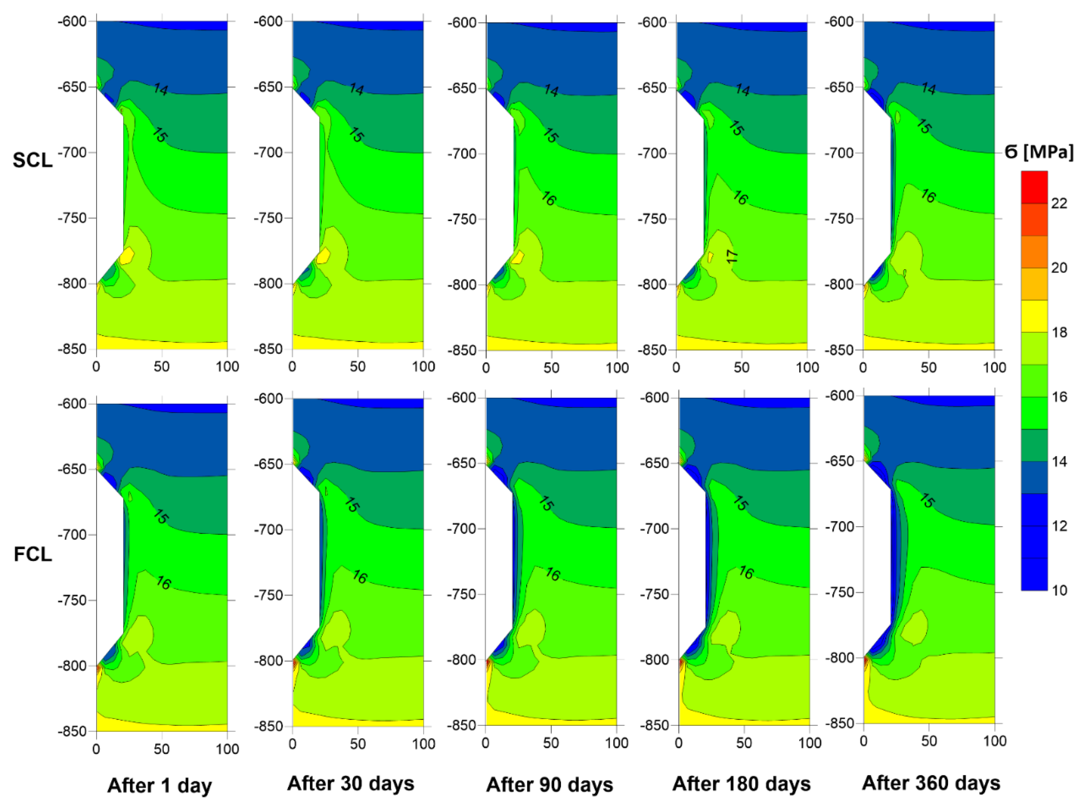
Figure 6 compares the stresses in the rock mass with the applied creep law.
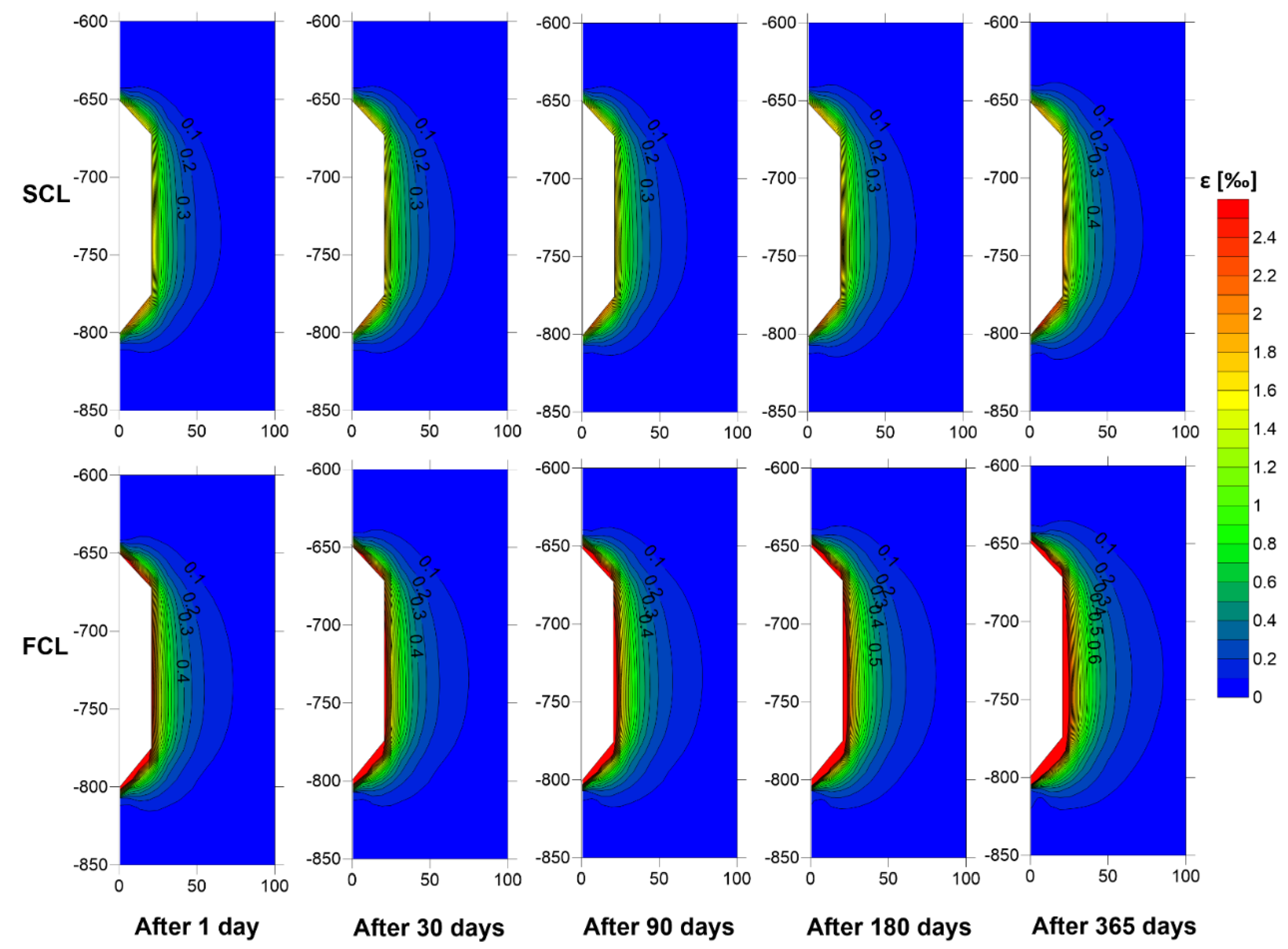
When comparing both the models used in the simulations (Figure 7), it was noticed that the applied creep law affects the values obtained up to a distance of 50 m from the cavern axis, regardless of the considered cavern point in a given case (ceiling, side wall, bottom). This translates into the real range of cavern impact differences, depending on the type of salt (fast-creeping or slow-creeping) up to a maximum of 23–24 m from the cavern wall (the considered model has a radius of 17.84 m). It should be noted that in slow-creeping salts the intermediate stresses in the rock mass in the immediate vicinity of the cavern are about 3 MPa higher than in fast-creeping salts.
When analyzing the results obtained for the deformation in model elements, it was noticed that the situation is opposite to the situation for stresses, i.e., in the fast-creeping model we deal with greater deformation in the immediate vicinity of the cavern than in the slow-creeping model. However, similar to the stresses, at a distance of approx. 23 m from the cavern axis, the strains begin to assume similar values. This means that in the case of fast-creeping salts, we deal with the greater phenomenon of stress relaxation.
It is worth noting that when analyzing the values of deformations in the model elements of the ceiling and the bottom, at a distance of 70 m from the cavern wall these deformations stabilize at the level of 0.00–0.01‰, which means that they are practically negligible. However, deformations of 0.01‰ in the side wall elements do not appear until 170 m from the cavern wall.

5. Influence of Temperature and Salt-Creep Speed on the Stability of the CAES Cavern

5.1. Strength Criteria and Rock Mass Effort

Researchers from Germany use the most precise criteria for assessing the stability of storage caverns. It is true that there are no unambiguously applicable limit values regarding the stress and deformation states in the cavern vicinity, but the three detailed criteria that were formulated and assessed by Lux et al. [18] were used to evaluate the stability of the cavern.
The first criterion concerns the maximum rock mass effort [18,25,26] and assumes that the maximum rock mass effort Wef at the edge of the cavern is [7]:
W e f = σ e f σ e f m a x ( σ m , θ , σ 3 )
σ e f m a x ( σ m , θ , σ 3 ) = [ 1 cos ( θ + π 6 ) + a s i n ( θ + π 6 ) ] exp ( b σ 3 ) σ e f T C ( σ m )
where:
θ = 1 3 a r c s i n ( 3 3 J 3 D 2 ( J 2 D ) 3 2 ) —Lode angle;
J 2 D = 1 3 σ e f 2 ;
J 3 D = s 1 1 · s 2 2 · s 3 3 ;
s i j = σ i j σ m · δ i j ;
σ m = 1 3 ( σ 1 1 + σ 2 2 + σ 3 3 ) —mean stress (MPa);
δ i j = { 1   f o r   i = j 0   f o r   i j —Kronecker delta;
a, b—constant coefficients (-);
σ e f T C ( σ m ) —strength in conventional triaxial compression tests (MPa).
At stress σ3, which is equal to the minimum gas pressure in the cavern, Wef cannot exceed 50% as this may result in loss of cavern stability.
The second criterion [18,25,26] concerns the effective stresses inside the interventricular pillar at the depth of the maximum stress at the wall. The effort in the distance L 2 D from the cavern axis (where L is distance between cavern axes, D is cavern diameter) may not exceed 30%.
The third criterion [18,25,26] concerns the maximum effective deformation at the cavern wall; it is assumed that the deformation increment during the pressure drop and the period when the cavern is under minimum pressure may not exceed 3%.
However, the precision of the short-term strength description, which depends on the degree of complication of the strength hypothesis, applies to typical salts, for which there is an extensive database of measurements and experiments. Therefore, when we have a limited amount of data, calculations using less complicated formulas turn out to be better. At the same time, it should be noted that the problem of long-term strength is still unsolved, hence it is recommended to assume a subjectively acceptable stress effort degree of the rock mass around a particular cavern within 30–40% of the short-term strength.
The basic parameters used in this study to analyze the stability of a cavern in a working CAES system were the effective stresses and strains. In addition to these two values, analysis of the rock mass around the cavern was also carried out in three model elements at the cavern walls: in the ceiling, on the side wall and at the bottom (respectively, elements 816, 504, 192 of the cavern mesh shown in Figure 5). The scenario of cyclic cavern operation lasting 365 days, as was described in Section 4, was analyzed. The effective stress hypothesis obtained by applying the formulas developed by Lux et al. [18] was used to assess the effort; three strength hypotheses are commonly used for these purposes:
Maximum principal stress hypothesis [7]:
W σ 1 m a x = σ 1 / σ 1 m a x
where:
σ1—principal stress (MPa)
σ 1 m a x = a σ 3 b + R c [27]
with parameters:
Rc = 20.6 (MPa)
a = 17.55 (-)
b = 0.692 (-)
Burzynski’s hypothesis [7]:
W B = 1 2 α R c [ 3 ( α 1 ) σ m + 9 ( α 1 ) 2 σ m 2 + 4 α σ e f 2 ]
where:
σ m = 1 3 ( σ 11 + σ 22 + σ 33 ) (MPa)
with parameters:
Rc = 20.6 (MPa)
α = 0.025 (-)
Huber’s hypothesis [7]:
W H = σ e f R c
In this case, based on the hypothesis of maximum principal stresses, the values of effective stresses can be analyzed:
W H = σ e f σ 1 m a x σ 3
with parameters as above [7].
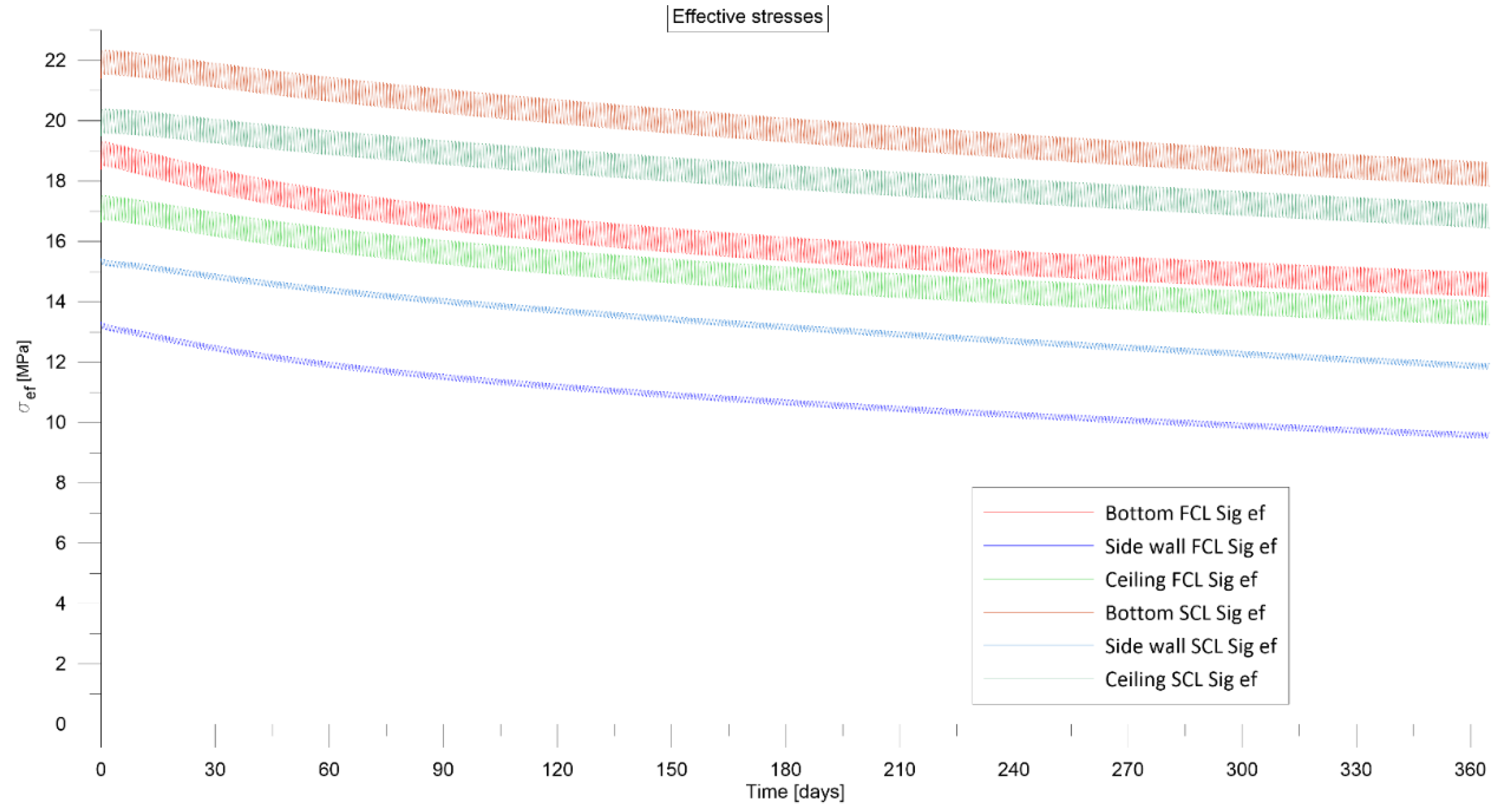
The highest values of the stresses are achieved immediately after emptying the cavern to the minimum pressure (Table 6). The intermediate values of the stresses are achieved after 6 h of cavern rest under minimum pressure and immediately after injection to the maximum pressure (Table 7 and Table 8) The lowest values of effective stresses were observed after the maximum pressure in the cavern stabilized (after the cavern had rested for 8 h at maximum pressure) (Table 9). Diagrams of effective stresses for the two creep laws (365-day cycles of cavern operation) are shown in Figure 8.
It should be noted that the differences in the values of effective stresses in extreme cases of cavern operation do not exceed 1 MPa.
When the cavern is continuously operated, the stresses in the considered elements decrease and, after the simulation of 365 daily cycles, their values are 3–4 MPa lower than the values determined after the first operation cycle. This was the case with both the fast- and slow salt-creep factors.
The effective stresses at each considered are lower when using the fast-creep law (FCL) than with the slow-creep law (SCL). This is due to the greater value of the n-factor used in this law, which means greater ability to reduce extreme stress. This situation occurs both when there is minimum and maximum pressure in the cavern; in both cases, the effective stress in the side wall element drops below 10 MPa.
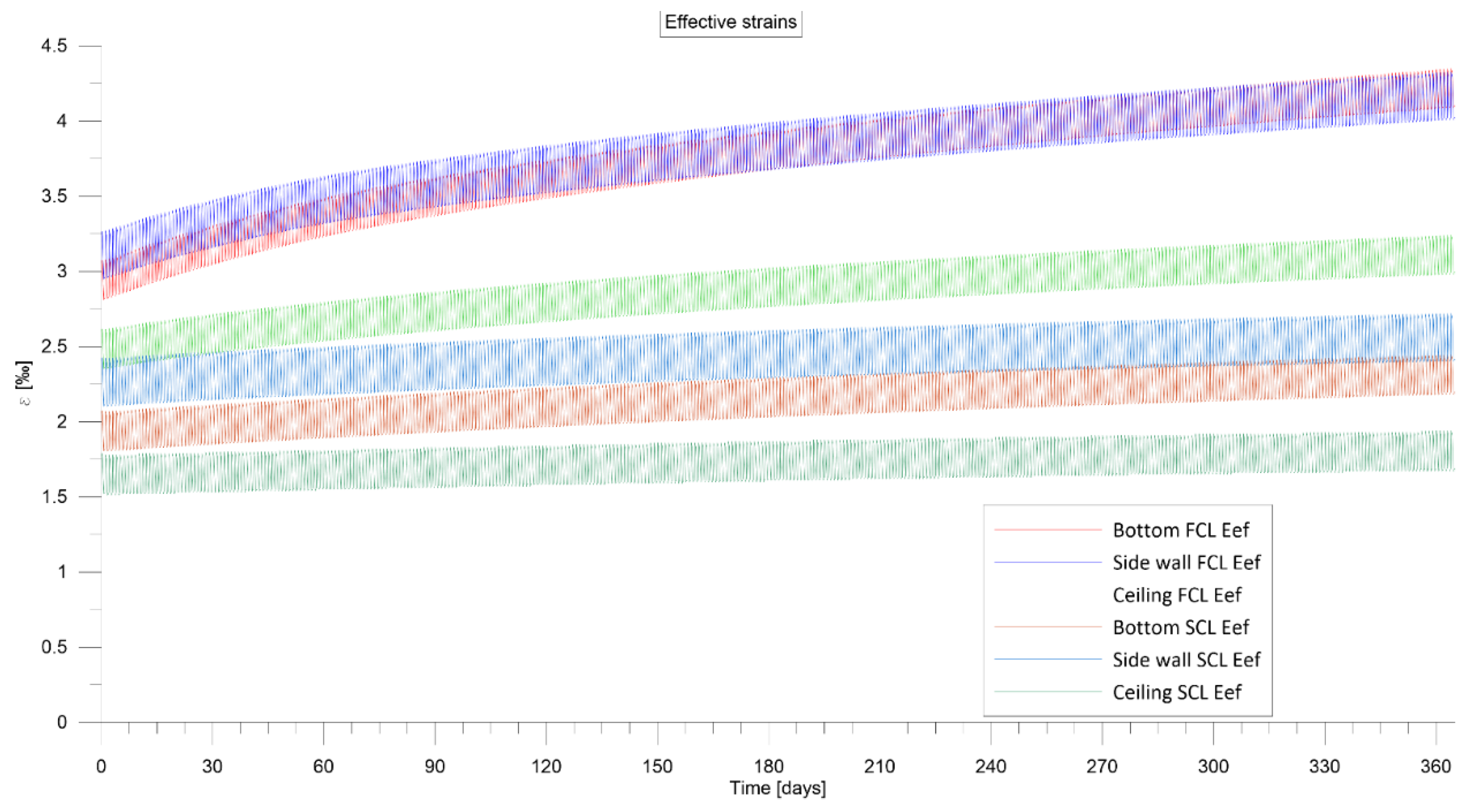
In the case of the slow-creep law, the effective deformations in the elements on the side wall and on the bottom increase by a maximum of 0.4‰ during a year of operation of the cavern. With the use of fast salt-creep, these deformations significantly increased compared to the first model and reached values from 0.5–0.6‰ for the considered element in the ceiling to 1.3‰ for the element in the bottom (Table 10 compares the values listed in Table 6, Table 7, Table 8 and Table 9). This situation was expected. The diagrams of effective strains obtained for the two creep laws (365-day cycles of cavern operation) are shown in Figure 9.
The stresses and effective strains are the most important in terms of cavern stability. Comparing the values obtained in the cavern wall elements against the stress values presented in the diagrams in Section 4, different ranges of cavern impact can be observed depending on which creep law was applied. It can be noticed that a greater reduction of stresses (fast-creep law) causes a greater increase in stresses in the rock mass, i.e., the range of cavern impact depends primarily on the type of salt (fast- or slow-creeping).
Different stress values cause differences in the obtained values of the rock mass effort coefficients in the considered elements at the wall of the cavern. The highest effort values are achieved by the Wef coefficient: in the element on the side wall, at the stage immediately after emptying the cavern on the first day of operation, it is equal to 50% (for the slow-creep law) (Appendix A Table A1). However, in no case does its value exceed the limits allowed by Hunsche and Lux et al.: 50% [18,25,26]. It should be emphasized that the Wef criterion determines the maximum effort that can be achieved in the rock mass, hence it should be assumed that the local stability of a CAES cavern operating under the assumed conditions will be maintained.
When analyzing the remaining strength criteria, it can be noticed that the highest values of the parameters describing the remaining hypotheses, WH’, W σ 1 m a x , WB, occur on the cavern side wall in stages immediately after emptying the cavern to the minimum pressure and after the cavern rested under the minimum pressure for 6 h (Appendix A Table A1 and Table A2). These values are similar in both stages, which may indicate a lack of stress relaxation in the rock mass in such a short period of time. With the passage of time of the cavern operation, the coefficients describing the effort of the rock mass begin to decrease, which indicates the relaxation of stresses in the rock mass despite the continuous cyclic operation of the cavern between the maximum and minimum pressure. It should be emphasized that the obtained values of these coefficients are so small that there is no risk of not maintaining cavern stability due to the use of insufficient minimum pressure.
Depending on the stage in question in individual work cycles, comparison of the obtained values of effective stresses and deformations (Appendix A Table A1, Table A2, Table A3 and Table A4) allows the conclusion that the deformation-stress state of the rock mass around the storage cavern undergoes some stabilization during operation of the cavern. This tendency is clearly noticeable for the simulations the with slow-creep law.
The annual increments of the strains presented in Table 10 are definitely lower than the permissible value defined by Lux et al.’s criteria, i.e., 3% [18,24,25]. It should also be noted that for the considered models, the stresses in the vicinity of the cavern wall drop below 12 MPa, especially in the side wall, which may lead to salt rock penetration.

5.2. Temperature Distribution in the Rock Mass Around CAES Cavern

During the operation of the CAES installation, rapid temperature changes occur in the cavern due to the injection of compressed air at a given temperature (35 °C) and the download of large amounts of stored air at a temperature of 15.2 °C for a very short period of time (2 h). Very high downloading and injection efficiency causes large temperature amplitudes.
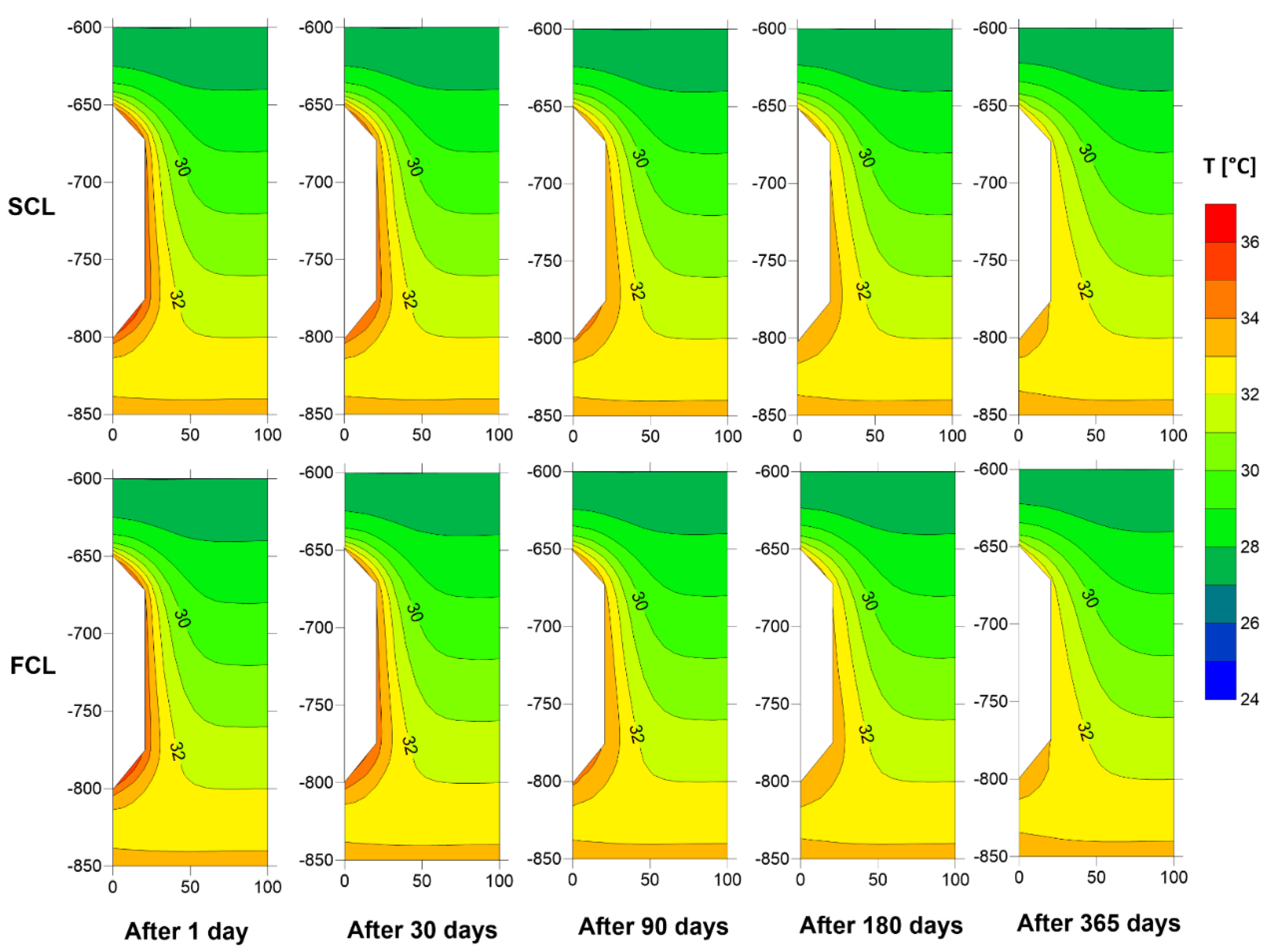
As a result of the numerical simulations, temperature distributions in the rock mass around the CAES storage cavern were calculated for the adopted scenarios. Figure 10 shows the maps of temperature distribution obtained at selected moments of the simulation, i.e., on the 1st, 30th, 90th, 180th and 365th day of operation.
Temperature fluctuations in the rock mass over the course of one day were about 1 °C. This is caused by the high specific heat of the rock mass and very fast temperature changes in the cavern. The range of temperature changes observed on these maps did not exceed 50 m from the cavern axis.
These maps show that at the beginning of the CAES cavern operation, the average temperature in the rock mass directly on the side wall increases; then, as the operation proceeds, the average temperature in the rock mass at all analyzed points drops by 2–3 °C compared to the value at the beginning of the operation time.

6. Conclusions

The performed numerical calculations show that the salt-creep process influences the stress variability in a range of up to 50 m from the cavern axis (approx. 23–24 m from the cavern wall in the considered model), regardless of the cavern point (ceiling, side wall, bottom). It should be noted that in slow-creeping salts, the stresses in the rock mass in the immediate vicinity of the cavern are greater than in fast-creeping salts.
The deformations obtained for fast-creeping salts show greater values in the immediate vicinity of the cavern than those obtained for slow-creeping salts. However, at a distance of approx. 23 m from the cavern axis, they have comparable values. This means that in the case of fast-creeping salts, we deal with a greater phenomenon of stress relaxation.
The highest effort values are achieved by the Wef coefficient, but in no case does its value exceed the permissible value according to Hunsche and Lux et al.’s criteria, i.e., 50% [18,25,26].
The highest values of the parameters described by hypotheses WH’, W σ 1 m a x , and WB occur on the cavern face in stages immediately after the cavern is emptied to the minimum pressure and after it is rested under the minimum pressure. During the exploitation of the CAES cavern, the coefficients describing the effort of the rock mass begin to decrease, which indicates the relaxation of stresses in the rock mass despite the continuous cyclic operation of the cavern between the maximum and minimum pressure. It should be noted here that the values of these coefficients, which were obtained as a result of the simulation, meet the adopted criteria, thus confirming that the temperature variation in the scope of the compressed air storage operation significantly affects the deformation-stress state of the cavern side, but it does not cause a loss of its stability. It should be expected that with many years of exploitation of the cavern, the deformation and stress state of the rock mass around the storage cavern will stabilize.
Annual deformation increments are definitely lower than the permissible value defined by Lux et al., i.e., 3% [18].
It should be emphasized that the CAES installation works when the demand for electricity in the network increases. The scenario adopted for the calculations was intended to verify the stability of the cavern in the most extreme load situation, when cyclic filling and emptying of the cavern occurs at very short intervals. The simulations show that it is possible to use CAES caverns even in the most extreme mode of operation. At the same time, it should be remembered that each case of a cavern located in a salt deposit should be considered individually, therefore it is necessary to conduct research (including numerical simulations) for each given case.

Funding

This research received no external funding.

Data Availability Statement

The data presented in this study are available on request from the corresponding author. The data are not publicity available due to company’s policy.

Acknowledgments

This work has been conducted under the author’s PhD thesis and Dean’s grant no. 15.11.190.688.

Conflicts of Interest

The author declares no conflict of interest.

Appendix A

Table A1. Strength criteria for the two salt-creep models. Status at the end of the downloading cycle (after emptying the cavern to the minimum pressure).
Time (Days) Cavern Pressure (MPa)Model TypeCeilingSide WallBottom
W H W σ 1 m a x W B W e f W H W σ 1 m a x W B W e f W H W σ 1 m a x W B W e f
14.45SCL0.140.220.150.350.200.280.240.500.150.230.180.37
FCL0.120.200.120.320.170.250.190.460.130.210.140.34
304.45SCL 0.140.220.150.340.190.270.230.490.150.230.170.36
FCL0.120.190.110.310.150.230.170.440.130.200.130.33
904.42SCL0.130.210.140.330.180.260.210.480.140.220.160.35
FCL0.110.190.110.300.140.220.150.420.120.200.120.31
1804.38SCL0.130.210.130.330.170.250.190.470.140.220.150.35
FCL0.110.180.100.290.130.210.130.410.110.190.110.30
3654.31SCL0.120.200.120.320.160.240.170.460.130.210.140.34
FCL0.100.170.090.280.120.200.120.410.110.180.100.29
Table A2. Strength criteria for the two salt-creep models. Status at the end of the emptying cycle (after 6 h of cavern rest under minimum pressure).
Time (Days) Cavern Pressure (MPa)Model TypeCeilingSide WallBottom
W H W σ 1 m a x W B W e f W H W σ 1 m a x W B W e f W H W σ 1 m a x W B W e f
14.67SCL0.130.220.150.350.190.270.230.490.150.230.170.36
FCL0.120.200.120.310.160.240.180.450.130.210.140.33
304.67SCL0.130.210.140.330.180.270.210.480.140.230.160.35
FCL0.110.190.110.300.150.230.160.420.120.200.120.32
904.64SCL0.130.210.130.330.170.260.200.470.140.220.150.35
FCL0.110.180.100.290.130.210.140.400.110.190.110.30
1804.60SCL0.120.200.130.320.160.240.180.460.130.210.150.34
FCL0.100.180.090.280.120.200.130.400.110.190.100.29
3654.52SCL0.120.200.120.310.150.230.160.440.130.210.130.33
FCL0.100.170.080.270.120.190.110.390.100.180.090.28
Table A3. Strength criteria for the two salt-creep models. Status at the end of the filling cycle (after injection to the maximum pressure).
Time (Days) Cavern Pressure (MPa)Model TypeCeilingSide WallBottom
W H W σ 1 m a x W B W e f W H W σ 1 m a x W B W e f W H W σ 1 m a x W B W e f
16.73SCL0.100.190.100.280.130.220.140.380.110.200.120.30
FCL0.080.170.070.240.100.190.100.330.090.180.090.26
306.73SCL0.100.190.090.270.130.210.130.370.110.200.110.29
FCL0.080.170.060.230.090.180.080.300.090.180.080.25
906.69SCL0.090.180.080.260.120.210.120.350.100.190.100.29
FCL0.070.160.060.220.080.170.070.280.080.170.070.23
1806.65SCL0.090.180.080.250.110.200.100.340.100.190.100.28
FCL0.070.150.050.200.070.160.060.260.080.160.060.22
3656.57SCL0.080.170.070.240.100.180.090.320.090.180.080.26
FCL0.060.140.040.190.070.150.050.260.070.150.050.21
Table A4. Strength criteria for the two salt-creep models. Status at the end of the work cycle (after 8 h of cavern rest at maximum pressure).
Time (Days) Cavern Pressure (MPa)Model TypeCeilingSide WallBottom
W H W σ 1 m a x W B W e f W H W σ 1 m a x W B W e f W H W σ 1 m a x W B W e f
16.63SCL0.100.190.100.280.130.220.140.390.110.200.120.30
FCL0.080.170.070.240.110.190.100.330.100.180.090.27
306.62SCL0.100.190.090.270.130.220.140.380.110.200.110.30
FCL0.080.170.070.230.090.180.080.310.090.180.080.25
906.58SCL0.100.180.090.270.120.210.120.360.110.200.110.29
FCL0.070.160.060.220.080.170.070.280.080.170.070.24
1806.54SCL0.090.180.080.260.110.200.110.350.100.190.100.28
FCL0.070.150.050.210.080.160.060.270.080.160.060.23
3656.46SCL0.090.170.070.240.100.180.090.330.100.180.090.27
FCL0.060.150.040.200.070.150.050.260.070.150.050.21

References

  1. Ślizowski, J.; Urbańczyk, K. Możliwości Magazynowania Gazu Ziemnego w Polskich Złożach Soli Kamiennej w Zależności od Warunków Geologiczno-Górniczych; IGSMiE PAN: Kraków, Poland, 2011. [Google Scholar]
  2. Crotogino, F. Compressed Air Storage. In Proceedings of the First International Renewable Energy Storage (IRES I) Conference, Gelsenkirchen, Germany, 30–31 October 2006. [Google Scholar]
  3. Robb, D. The CAES for wind. Renew. Energy Focus 2011, 12, 18–19. [Google Scholar] [CrossRef]
  4. Ślizowski, J.; Urbańczyk, K.; Lankof, L.; Serbin, K. Selection of Possible Locations of Underground Storage Tanks for Energy Storage in the Form of Compressed Air from the Point of View ot the Use Underground Geological Structures in the Indicated Areas of Poland—Wytypowanie Możliwych Lokalizacji Podziemnych Zbiorników do Magazynowania Energii w Postaci Sprężonego Powietrza z Punktu Widzenia Wykorzystania Podziemnych Struktur Geologicznych we Wskazanych Obszarach Polski; IGSMiE PAN: Cracow, Poland, 2011; unpublished. [Google Scholar]
  5. Khaledi, K.; Mahmoudi, E.; Datcheva, M.; Schanz, T. Analysis of compressed air storage caverns in rock salt considering thermo-mechanical cyclic loading. Environ. Earth Sci. 2016, 75, 1–17. [Google Scholar] [CrossRef]
  6. Perazzelli, P.; Anagnostou, G. Design issues for compressed air energy storage in sealed underground cavities. J. Rock Mech. Geotech. Eng. 2016, 8, 314–328. [Google Scholar] [CrossRef] [Green Version]
  7. Ślizowski, J. Geomechaniczne Podstawy Projektowania Komór Magazynowych Gazu Ziemnego w Złożach Soli Kamiennej; Wydawnictwo IGSMiE PAN: Kraków, Poland, 2006. [Google Scholar]
  8. Polański, K. Numerical calculations of main stress in the rock massif around salt cavern for compressed air storage. IOP Conf. Ser. Earth Environ. Sci. 2019, 214, 012079. [Google Scholar] [CrossRef]
  9. Kushnir, R.; Dayan, A.; Ullmann, A. Temperature and pressure variations within compressed air energy storage caverns. Int. J. Heat Mass Transf. 2012, 55, 5616–5630. [Google Scholar] [CrossRef]
  10. Raju, M.; Khaitan, S.K. Modeling and simulation of compressed air storage in caverns: A case study of the Huntorf plant. Appl. Energy 2012, 89, 474–481. [Google Scholar] [CrossRef]
  11. Xia, C.; Zhou, Y.; Zhou, S.; Zhang, P.; Wang, F. A simplified and unified analytical solution for temperature and pressure variations in compressed air energy storage caverns. Renew Energy 2015, 74, 718–726. [Google Scholar] [CrossRef]
  12. Berest, P.; Djizanne, H.; Brouard, B.; Hevin, G. Rapid depressurization: Can they lead to irreversible damage? In Proceedings of the SMRI Conference, Regina, SK, Canada, 23–24 April 2012. [Google Scholar]
  13. Berest, P.; Brouard, B.; Djakeun-Djizanne, H.; Hevin, G. Thermomechanical effects of a rapid depressurization in a gas cavern. Acta Geotech. 2013, 9, 181–186. [Google Scholar] [CrossRef]
  14. Berest, P.; Brouard, B.; Jafari, M.K.; Sambeek, L.V. Thermomechanical aspects of high frequency cyclic in salt storage caverns. In Proceedings of the International Gas Union Research Conference, Seoul, Korea, 19–21 October 2011. [Google Scholar]
  15. Skorek, J.; Banasiak, K. Thermodynamic Analysis of the Compressed Air Energy Systems operation. Inżynieria Chem. Proces. 2007, 27, 187–200. [Google Scholar]
  16. He, W.; Luo, X.; Evans, D.; Busby, J.; Garvey, S.; Parkes, D.; Wang, J. Exergy storage of compressed air in cavern and cavern volume estimation of the large-scale compressed air energy storage system. Appl. Energy 2017, 208, 745–757. [Google Scholar] [CrossRef]
  17. Serbin, K. Wpływ Parametrów Termodynamicznych Procesu Magazynowania Gazu na Pojemność Kawerny w Złożu Soli Kamiennej. Ph.D. Thesis, AGH-UST, Kraków, Poland, 2013. [Google Scholar]
  18. Lux, K.-H.; Hou, Z.; Düsterloh, U. Some New Aspects in Modelling of Cavern Behavior and Safety Analysis. In Proceedings of the SMRI Meeting, Rome, Italy, 4–7 October 1998. [Google Scholar]
  19. Ślizowski, J.; Serbin, K. Wpływ Zmienności Temperatury na Stan Deformacyjno-Naprężeniowy Górotworu w Otoczeniu Komory Magazynowej Gazu; Statutory work of IGSMiE PAN: Cracow, Poland, 2012; unpublished. [Google Scholar]
  20. Urbańczyk, K.; Ślizowski, J. An attempt to asses suitability of middle-Poland salt domes for natural gas storage. Arch. Min. Sci. 2012, 57, 335–349. [Google Scholar]
  21. Wang, S.Y.; Wu, J.L. Optimal sizing of the CAES system in a power system with high wind power penetration. Int. J. Electr. Power Energy Syst. 2012, 37, 117–125. [Google Scholar] [CrossRef]
  22. Dzierżanowski, Ł. Elektrownie CAES. Energia Elektryczna—nr 2-3/2011; Oficyna Wydawnicza Energia [Stowarzyszenie Elektryków Polskich - COSiW]: Warsaw, Poland, 2011. [Google Scholar]
  23. Kuczyński, S.; Skokowski, D.H.; Włodek, T.; Polański, K. Compressed air energy storage as backup generation capacity combined with wind energy sector in Poland implementation possibilities. AGH Drill. Oil Gas 2015, 32, 23–32. [Google Scholar] [CrossRef] [Green Version]
  24. Samotyj, M. Złapać Wiatr i Pod Ziemię! Materiały Problemowe Cire; Centrum Informacji o Rynku Energii: Warsaw, Poland, 2012. [Google Scholar]
  25. Hunshe, U. True Triaxial Failure Tests on Cubic Rock Salt Samples—Experimental Methods and Results. In Proceedings of the IUTAM-Symposium—Hannover; Springer: Berlin/Heidelberg, Germany, 1991. [Google Scholar]
  26. Hunshe, U. Uniaxial and Triaxial Creep and Failure Tests on Rock: Experimental Technique and Interpretation. In Uniaxial and Triaxial Creep and Failure Tests on Rock: Experimental Technique and Interpretation; Cristescu, N.D., Gioda, G., Eds.; Springer: Vienn, Austria, 1994; Volume 350. [Google Scholar]
  27. Ślizowski, J.; Urbańczyk, K. Influence of Depth on Rock Salt Effort around the Single Chamber; IGSMiE: Cracow, Poland, 2004. [Google Scholar]
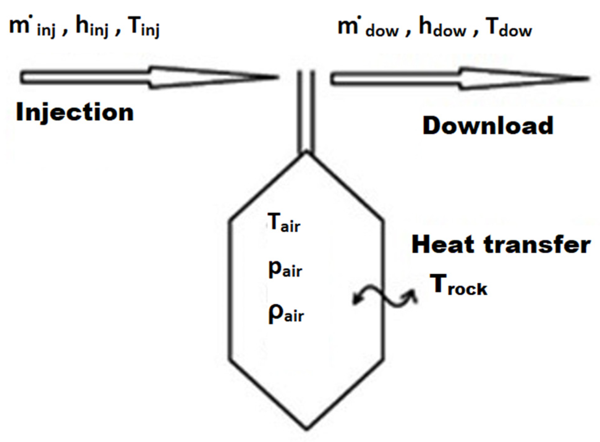
Figure 1. Considered parameters during the injection and download processes from a cavern [5].
Energies 14 06197 g001
Figure 2. Stress-strain characteristics of the rheological medium [7].
Energies 14 06197 g002
Figure 3. Deformation phases of salt rock [17].
Energies 14 06197 g003
Figure 4. Schematic presentation of the modeling procedure of the CAES cavern operation cycle.
Energies 14 06197 g004
Figure 5. Cavern mesh adopted for numerical calculations with marked elements on the ceiling, wall and bottom, i.e., where the effort of the rock mass was assessed.
Energies 14 06197 g005
Figure 6. Comparison of stress distributions in the rock mass at the end of 1, 30, 90, 180 and 365 days of CAES cavern operation for models with slow-(SCL) and fast-creep law (FCL), with temperature changes in the rock mass.
Energies 14 06197 g006
Figure 7. Comparison of the deformations of the cavern wall at the end of 1, 30, 90, 180 and 365 days of CAES cavern operation for the slow- (SCL) and fast-creep law (FCL) models, and the temperature changes in the rock mass were also implemented.
Energies 14 06197 g007
Figure 8. Comparison of the effective stresses obtained for the slow-(SCL) and fast-creep law (FCL) models, with temperature changes in the rock mass for the considered elements on the cavern contour.
Energies 14 06197 g008
Figure 9. Comparison of the effective strains obtained for the slow-(SCL) and fast-creep law (FCL) models, with temperature changes in the rock mass for the considered elements on the cavern contour.
Energies 14 06197 g009
Figure 10. Temperature distribution in the rock mass at the end of 1, 30, 90, 180 and 365 days of CAES cavern operation.
Energies 14 06197 g010
Table 1. The adopted values of the coefficients for the two creep laws.
ModelA (‰)Q/R (K)Ndε/dt * (‰/day)
Slow-creep Law (SCL)219.65650040.004
Fast-Creep Law (FCL)175.72650050.032
* speed obtained for σef = 10 MPa and temperature T = 323 K.
Table 2. Thermal properties of salt adopted in the model.
Thermal conductivity of the salt rock mass (W/m⋅K)6.5
Thermal diffusivity of the rock mass (m2/s)0.45⋅10−5
Salt density (kg/m3)2155
Heat transfer in salt (W/m2⋅K)50
Temperature gradient αrock (K/m)0.025
Factor β298
The considered interval (m)0–2000
Table 3. Gas (air) parameters adopted in the model.
DownloadInjection
Temperature at the wellhead (°C)15.235
Pressure at the wellhead (bar)64.7570
Air density (kg/m3)80.12880.239
Table 4. Air flow during download/injection.
DownloadInjection
Air flow (kg/s)417108
Air flow (kg/h)1,501,200388,800
Air flow (Nm3/h)1,164,932301,709
Pressure change (in the cavern) (MPa/h)10.25
Time of step (h)28
Table 5. Foundation depth and geometrical parameters of the cavern adopted for modeling.
Ceiling depth (m)650
Bottom depth (m)800
Cavern radius (m)17.841
Volume (m3) 149,996
Internal diameter of the exploitation pipes (m)0.508 (20″)
Heat transfer in the well (W/m2K)15
Heat transfer in the rock mass (W/m2K)50
Table 6. Strength criteria for the two salt-creep models. Status at the end of a given downloading cycle (after emptying the cavern to the minimum pressure).
Time (Days) Pressure in Cavern (MPa)Model TypeCeilingSide WallBottom
σ e f
(MPa)
ε e f
(‰)
σ e f
(MPa)
ε e f
(‰)
σ e f
(MPa)
ε e f
(‰)
14.45SCL20.391.7915.302.4322.332.07
FCL17.532.6213.183.2619.323.07
304.45SCL 20.081.8014.812.4621.942.11
FCL17.002.7112.443.4718.453.30
904.42SCL19.371.8313.992.5321.072.19
FCL16.072.8611.483.7417.213.63
1804.38SCL18.561.8713.132.6120.112.29
FCL15.183.0210.643.9916.173.93
3654.31SCL17.251.9411.822.7218.642.45
FCL14.043.249.524.3314.994.35
Table 7. Strength criteria for the two salt-creep models. Status at the end of a given emptying cycle (after 6 h of cavern rest under minimum pressure).
Time (Days) Pressure in Cavern (MPa)Model TypeCeilingSide WallBottom
σ e f
(MPa)
ε e f
(‰)
σ e f
(MPa)
ε e f
(‰)
σ e f
(MPa)
ε e f
(‰)
14.67SCL20.351.7515.222.3922.302.04
FCL17.482.5913.103.2319.273.04
304.67SCL20.021.7714.742.4321.882.08
FCL16.942.6912.373.4418.383.27
904.64SCL19.311.8013.922.4921.022.16
FCL16.012.8311.413.7117.153.60
1804.60SCL18.501.8413.062.5720.052.26
FCL15.122.9910.573.9616.113.90
3654.52SCL17.201.9111.752.6918.582.42
FCL13.993.219.464.2914.934.32
Table 8. Strength criteria for the two2 salt- creep models. Status at the end of a given filling cycle (after injection to the maximum pressure).
Time (Days) Pressure in Cavern (MPa)Model TypeCeilingSide WallBottom
σ e f
(MPa)
ε e f
(‰)
σ e f
(MPa)
ε e f
(‰)
σ e f
(MPa)
ε e f
(‰)
16.73SCL19.621.5215.392.1021.571.80
FCL16.752.3513.272.9518.532.81
306.73SCL19.291.5314.922.1421.141.85
FCL16.202.4512.553.1517.643.04
906.69SCL18.581.5614.102.2120.281.93
FCL15.272.6011.603.4316.413.37
1806.65SCL17.771.6113.252.2919.322.03
FCL14.392.7610.753.6715.383.67
3656.57SCL16.471.6711.942.4017.862.18
FCL13.262.989.654.0114.204.09
Table 9. Strength criteria for the two salt-creep models. Status at the end of a given work cycle (after 8 h of cavern rest at maximum pressure).
Time (Days) Pressure in Cavern(MPa)Model TypeCeilingSide WallBottom
σ e f
(MPa)
ε e f
(‰)
σ e f
(MPa)
ε e f
(‰)
σ e f
(MPa)
ε e f
(‰)
16.63SCL19.581.5315.402.1221.531.82
FCL16.712.3713.272.9618.502.82
306.62SCL19.251.5414.932.1621.101.86
FCL16.162.4712.563.1717.603.06
906.58SCL18.541.5814.122.2220.241.94
FCL15.242.6211.613.4416.383.38
1806.54SCL17.731.6213.262.3019.292.04
FCL14.362.7710.773.6915.353.69
3656.46SCL16.441.6911.952.4217.822.20
FCL13.222.999.664.0214.174.10
Table 10. Annual increase of effective strains.
ModelIncrease in Strain (‰/year) (State at the End of the Work Cycle)
CeilingSide WallBottom
Slow-creep Law0.160.300.38
Fast-creep Law0.621.061.28
Publisher’s Note: MDPI stays neutral with regard to jurisdictional claims in published maps and institutional affiliations.