Article

Design and Realization of a Hybrid Excited Flux Switching Vernier Machine for Renewable Energy Conversion

1
GREAH, Université Le Havre Normandie, 76600 Le Havre, France
2
SATIE, Conservatoire National des Arts et Métiers, 75003 Paris, France
3
Advanced Electromagnetics B.V., Industrieweg 78, 5145 PW Waalwijk, The Netherlands
*
Author to whom correspondence should be addressed.
Energies 2021, 14(19), 6060; https://doi.org/10.3390/en14196060
Submission received: 29 July 2021 / Revised: 9 September 2021 / Accepted: 18 September 2021 / Published: 23 September 2021
(This article belongs to the Special Issue Energy and Exergy Analysis of Renewable Energy Conversion Systems)

Abstract

:
This paper presents the design of a hybrid excited flux switching Vernier machine. This machine is designed to serve in renewable energy conversion applications, such as a wind turbine generator, or tidal turbine generator. After introducing this original structure, a design based on finite element models is conducted. The specifications correspond to relatively low power direct drive wind or tidal turbine applications. The rated power is set to 10 kW, with a rated speed of 300 rpm. Mainly the electromagnetic design is presented. Aspects related to the realization of a prototype are also presented, and an experimental study is included.

1. Introduction

Problems linked to the use of fossil fuels are pushing our societies to find viable and sustainable alternatives for their replacement. The use of nuclear energy, even if it emits less polluting greenhouse gases, does not cause fewer problems. Indeed, radioactive wastes, the products of nuclear power plants, have a lifespan that exceeds several generations, the management of which is problematic.
In this context, renewable energies constitute a viable and lasting solution, since their potential is enormous, and they do not emit greenhouse gases. The French Environment and Energy Management Agency (Ademe), aims that France should produce, by 2050, 100% of its electrical energy from renewable energies at acceptable economic costs [1]. Among the different renewable energy sources, marine renewable energies (MRE), i.e., offshore wind, wave energy (wave power) and tidal turbines, are those that offer the least intermittency problems [2]. Tidal turbines, for example, harness the energy of oceanic marine currents which are continuous over time, or that of tidal currents which are relatively predictable [2]. France has a strong development potential for MRE, given the natural assets of its territory (11 million km2 of water under its jurisdiction) [3]. This known resource, estimated between 2 and 3 GW, is mainly concentrated off the coasts of Normandy, Brittany and Pays de la Loire [3].
In this paper, the electromagnetic design of a hybrid excited flux switching synchronous machine with a Vernier effect is presented [4]. Its structure is inspired by works carried out on flux switching machines which include hybrid excitation [5,6,7], and those including the Vernier effect [8,9]. A similar structure was the subject of a Chinese patent [4]. Such structures can be qualified as original, and are not well studied. Furthermore, the structure studied in this research also includes damper windings used for the mitigation of voltage induced in the wound field excitation windings [10,11,12,13,14]. This structure can be used as a generator (alternator) in low-speed applications such as direct drive wind turbines or tidal turbines. After a presentation of the structure of this machine, sizing based on finite element method models is proposed. The sizing is carried out on the basis of specifications for a direct drive wind turbine of 10 kW, rotating at a speed of 300 rpm [15]. Some elements concerning the realization of a prototype are also presented.
Vernier effect machines [16,17] are well suited to low speed, high torque applications, which is characteristic of renewable energy applications. Furthermore, flux-switching machines have structures where all the sources of magnetic fields can be placed in a fixed part. This allows efficient cooling, and therefore better performance stability. In addition, the use of double excitation reduces the need for high-performance rare earth magnets, the extraction of which is extremely polluting, while allowing better controllability of performance. It is also possible to replace high-performance magnets with ceramic magnets (ferrite magnets).
The use of hybrid-excited machines in renewable energy applications, and more specifically wind power, has been the subject of several studies over the past two decades [18,19,20,21,22,23,24,25,26,27]. In reference [21], the author shows that double-excited machines can be an economically attractive solution compared to conventional machines with permanent magnets based on rare earths.

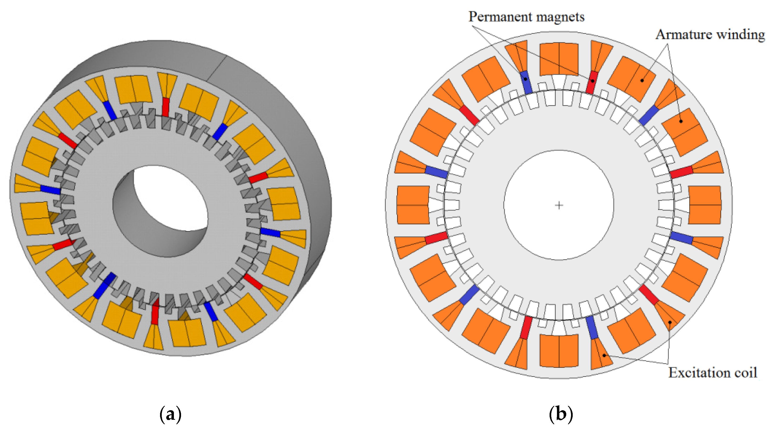
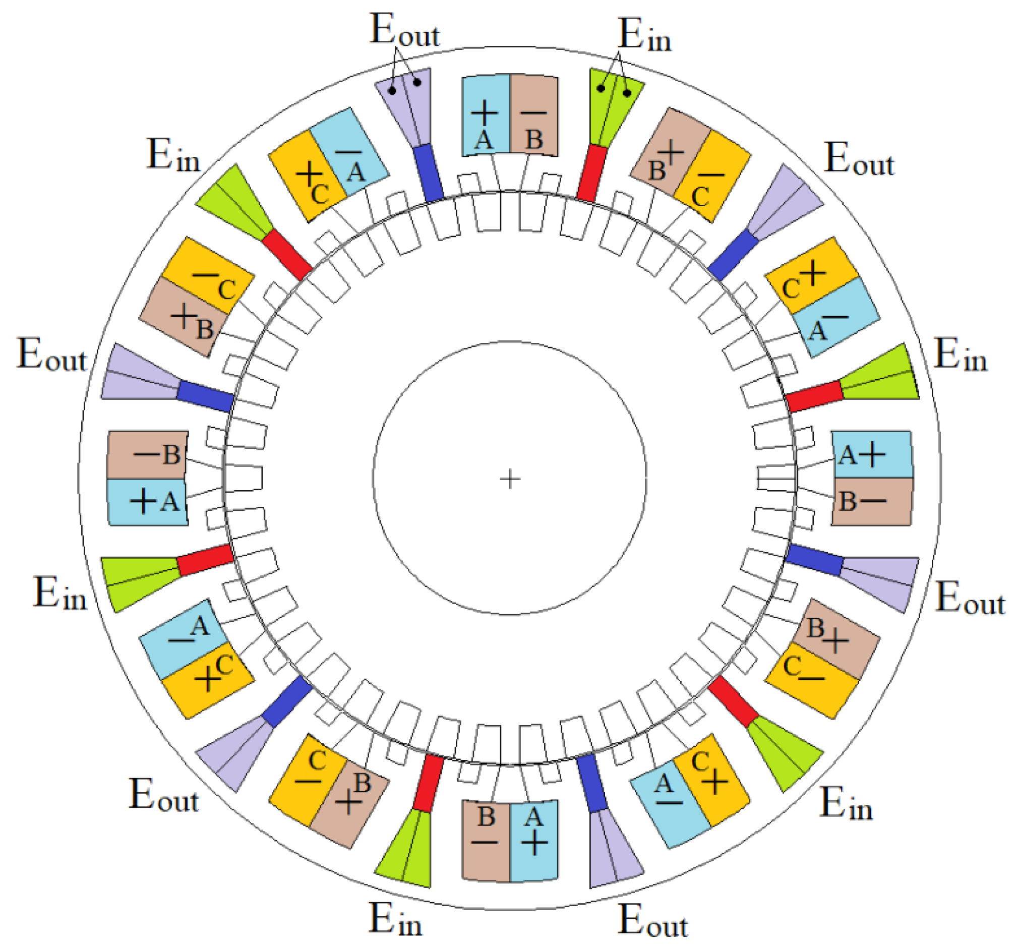
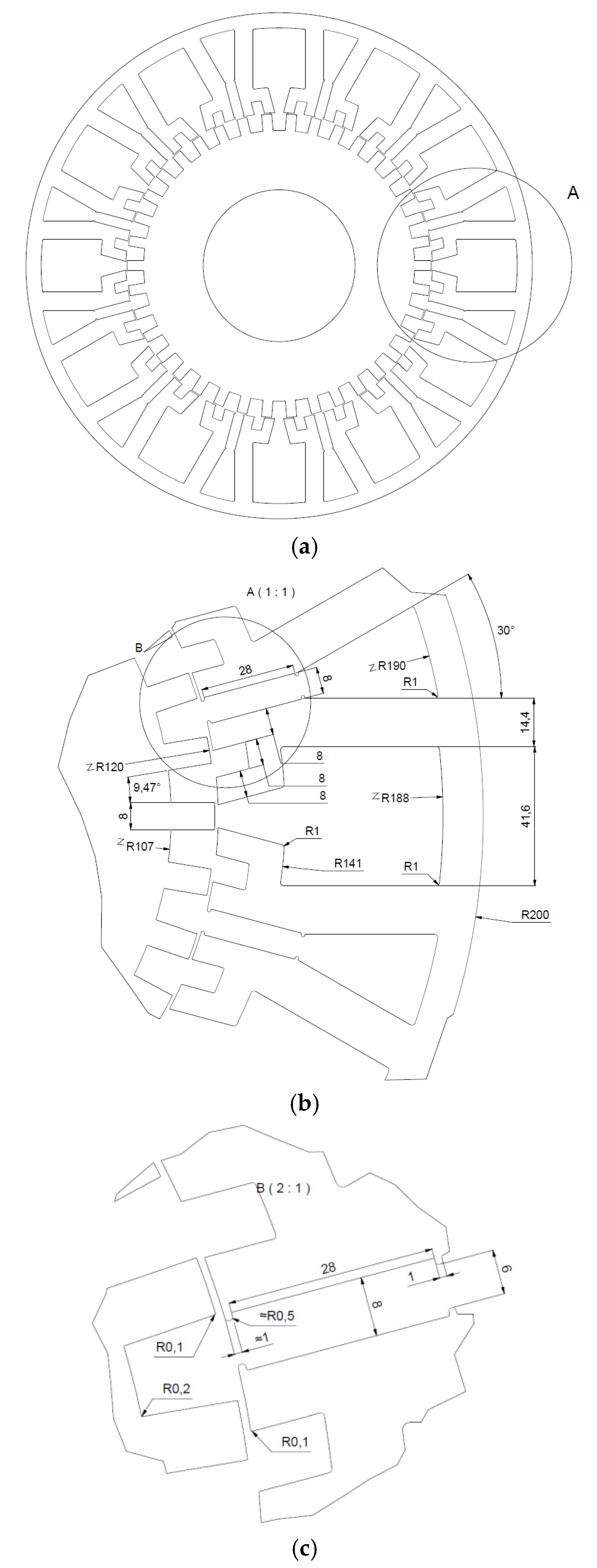
2. Structure and Electromagnetic Design of Studied Machine

Table 1 lists some elements of the specifications on which the design of the studied structure is based. These are specifications used at GREAH laboratory as a reference for comparing several prototypes [15,28]. Figure 1 shows the structure of the studied machine. It is a flux-switched hybrid-excited synchronous machine, also including the Vernier effect [4,5,6,7,8,9]. While sharing similarities with the structure presented in [4], the number of stator modules and rotor teeth are different.
The dimensions were obtained by applying homothetic rules from the cited works. Figure 2 shows detailed dimensions of the stator and rotor. It is a three-phase machine, having 12 stator modules, each including a permanent magnet, a slot for the armature windings, and a slot for the excitation winding. The rotor is completely passive, and has 38 teeth. By having an even number of rotor teeth, the unbalanced magnetic force is null if the rotor is well centered.
The numbers of turns for the two types of windings, armature and excitation, are given in Table 1. The number of turns of the armature windings is calculated to be consistent with the voltage levels of GREAH laboratory installations (three-phase 230 V/400 V grid). In order to efficiently remove losses from the stator, water cooling is adopted. The water jacket is made of nonmagnetic material to avoid further short-circuiting the permanent magnets flux and therefore reduce the armature magnetic flux linkage.
Figure 3 shows the armature windings and the excitation winding distributions. The armature windings are composed of concentrated coils. This helps to reduce the end windings’ lengths. There is no overlap between the windings of the three phases. However, there is an overlap between the armature windings and the field excitation winding.
One of the issues related to the presence of excitation windings in flux switching machines is the induced voltage that may be experienced by these windings [10,11,12,13,14]. To address this issue, a solution developed at SATIE laboratory was adopted [29]. It consists of adding damping windings (DW) along the two other windings sets, i.e., armature and wound field excitation windings. This solution consists in having, along with the excitation coils, coils wound the same way as the excitation coils, and short circuited. Doing so, the current induced in the short-circuited coil helps reduce the pulsating flux responsible for the induced voltage pulsation. More details are provided in the sections dedicated to the prototype construction and experimental study.

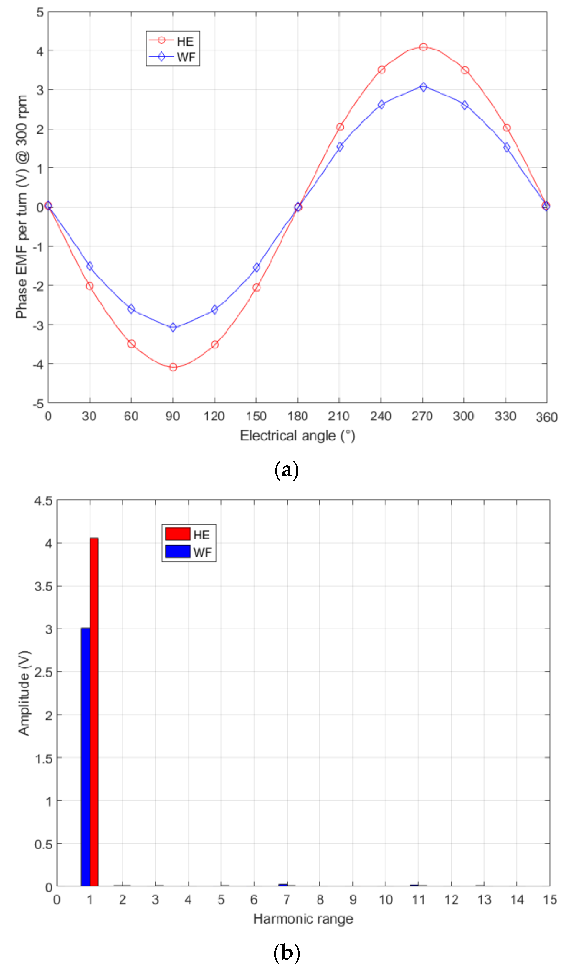
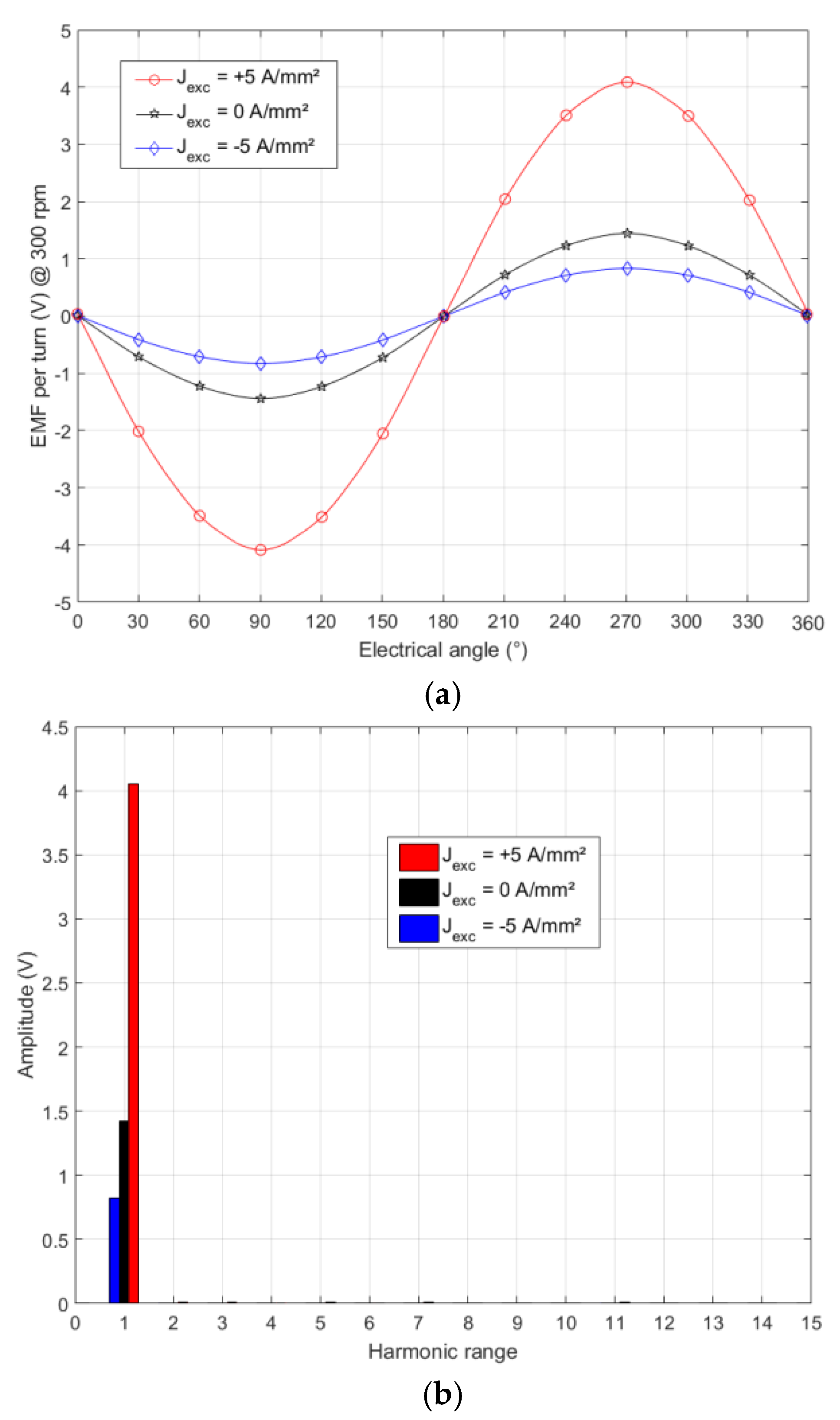
3. Performance Analysis

The 2D finite element method (FEM) was used for the study of machine performance. Figure 4 shows the meshed studied domain. The ratio between the air-gap radius and the active length is consistent with the use of a 2D FEM approach.
Taking into account the geometrical and physical symmetries, it is sufficient to model half of the machine (Figure 4a). Figure 4b shows a zoom in on the region of the air gap, which should be given special attention. The elements size discretization imposed to the points and the lines belonging to the air-gap region was set to 1/6 mm. This discretization was imposed to have a sufficient number of elements to get useful information when computing the cogging torque, or the torque ripples. Indeed, the period of cogging torque is equal to
α m e c . = 360 ° / L C M ( 12 , 38 ) 1.579 ° ,
which corresponds to a distance of approximately 3.31 mm at the rotor outer radius.
The machine’s external environment was modeled using a device called an “infinite box” [30]. The mesh consists of 69,626 surface elements of the second order, with 139,495 nodes. Details about the mesh are given in Figure 5. The calculations are mainly carried out in magneto-static mode with the vector potential as unknown. For the computation of permanent magnets eddy current loss, the magneto-dynamic mode was adopted. Magnetic saturation was considered in this study. Figure 6 shows the B(H) curve of the material used for the ferromagnetic parts. Circuit coupling was adopted to model the armature windings and the excitation winding, and was also adopted when computing the permanent magnets eddy current loss. This coupling was configured to ensure that a null net total current flows in each permanent-magnet surface [31].
Figure 7 compares the EMFs of the structure in its pure wound-field (WF) version (the permanent magnets are replaced by the air) and hybrid-excited (HE) version for Jexc = 5 A/mm2 (current density of the excitation current). The hybrid excitation allows an increase in excitation flux linkage of 35% compared to the wound-field excitation version.
The period, in mechanical angles, of the FEMs is equal to:
θ m e c . = 360 ° / 38 9 . 4737 ° ,
where the number 38 corresponding to the number of rotor teeth and constitutes the number of pairs of poles (p = 38). The waveforms of FEMs are very close to a sinusoid, with a fairly low harmonic content.
Figure 8 shows the EMF waveforms for different values of the excitation current and compares their harmonic contents. As before, the EMF waveforms are very close to sinusoid. It can be seen that adding excitation flux is more efficient than reducing it. Figure 9 shows the cogging torque waveforms of different values of excitation current.
Figure 10 shows the variation of the load torque for two values of the excitation current density Jexc = 0 and 5 A/mm2. The RMS value of armature current density was set to 5 A/mm2. The load torque was estimated for an armature current in phase with the EMF in each phase (ψ = 0°). The fill factor for the armature windings and the excitation coils was identical, and equal to 40%. Figure 11 shows variation of the load torque with the angle ψ. These computations were done for an RMS value of armature current density JArm. = 5 A/mm2, and Jexc = 5 A/mm2. The machine behaves as a nonsalient synchronous machine. Figure 12a shows the torque waveforms for different values of the RMS value of armature current density JArm., for Jexc = 5 A/mm2. The armature current is in phase with the EMF in each phase (ψ = 0°), for these computations. Figure 12b shows the variation of the mean value of the torque with the armature current density RMS value.
The nominal torque for a nominal power of 10 kW at a nominal rotation speed of 300 rpm was equal to ≈318 N.m. This value was reached for an armature current density RMS value of nearly 5 A/mm2 when Jexc = 5 A/mm2.
Figure 13 shows the torque ripple ratio for the different values of the armature current corresponding to the torque waveforms shown in Figure 12a. This ratio is computed as
T R r = T m a x T m i n T a v e r a g e
The torque ripple ratio was less than 12% for the analyzed waveforms. For Jexc = 5 A/mm2 and JArm. = 5 A/mm2, this ratio was equal to 7.3%. It is possible to reduce it by optimizing the dimensions of the machine. It would also be possible to look for the best combination (Jexc, JArm.) to reduce it while keeping the torque at its nominal value.
Figure 14 shows the magnetic state of the structure for a given position for Jexc = 5 A/mm2 and JArm. = 5 A/mm2; the armature current being in phase with the EMF in each phase. As can be seen, some areas of the machine are well saturated, and it is in the stator and rotor teeth that this is more particularly pronounced.
Figure 15 shows the phase voltage (Figure 15a) and the armature current (Figure 15b) for a given phase when Jexc = 5 A/mm2 and JArm. = 5 A/mm2, the armature current being in phase with the EMF in each phase (ψ = 0°).
It can be seen from the curves in Figure 15 that the power factor for this operation is relatively low (FP ≈ 0.147). This is a characteristic of Vernier machines. It should be noticed that such low values have been reported by the authors of reference [6] for a hybrid excited flux switching machine not including the Vernier effect.
Figure 16 shows the harmonic content of the phase voltage (Figure 15a). The magnetic armature reaction is very important as compared to the excitation flux linkage, and its harmonic content is relatively rich.
Considering the low value of the power factor for this operating point, an alternative combination (Jexc, JArm.) was sought making it possible to respond to the nominal torque while improving the PF. Figure 17 shows the torque for Jexc = 10 A/mm2 and JArm. = 2.75 A/mm2, the armature current being in phase with the EMF in each phase. This allows the magnetic armature reaction to be reduced, thus increasing the PF. The power factor FP for this operation was 0.254.
Table 2 shows the loss balance for the two studied operations, for which the armature current is in phase with the EMF in each phase (ψ = 0°): Operation 1 (F1) (Jexc = 5 A/mm2, JArm. = 5 A/mm2), Operation 2 (F2) (Jexc = 10 A/mm2, JArm. = 2.75 A/mm2). Joule losses were estimated without taking the end-windings into account. Iron losses were estimated by the “Loss Surface” method available in Flux2D software [32].
Eddy current losses in permanent magnets are estimated considering that they are not segmented. Their segmentation in the radial and axial directions allows a significant reduction of these losses [33,34]. The significant difference in these losses for the two operations is related to the state of magnetic saturation, which is more heterogeneously distributed in the areas near the permanent magnets in the case of the first operation (F1). It should be noted that the iron losses in the rotor were respectively 114.62 W and 89.72 W for the two operations F1 and F2, respectively. The main iron losses component corresponded to the stator iron losses.
The efficiency η was estimated considering that the machine was operating in generator mode (alternator) using following formula
η = T Ω P L o s s T Ω ,
with (T·Ω) is the provided mechanical power and PLoss the total loss.
It is important to retain from this performance analysis study, the additional degree of freedom offered by the use of hybrid excitation. The hybrid excitation allows controlling the air-gap magnetic field, and the selection of an adequate (Jexc, JArm.) combination to improve the efficiency and/or the power factor.

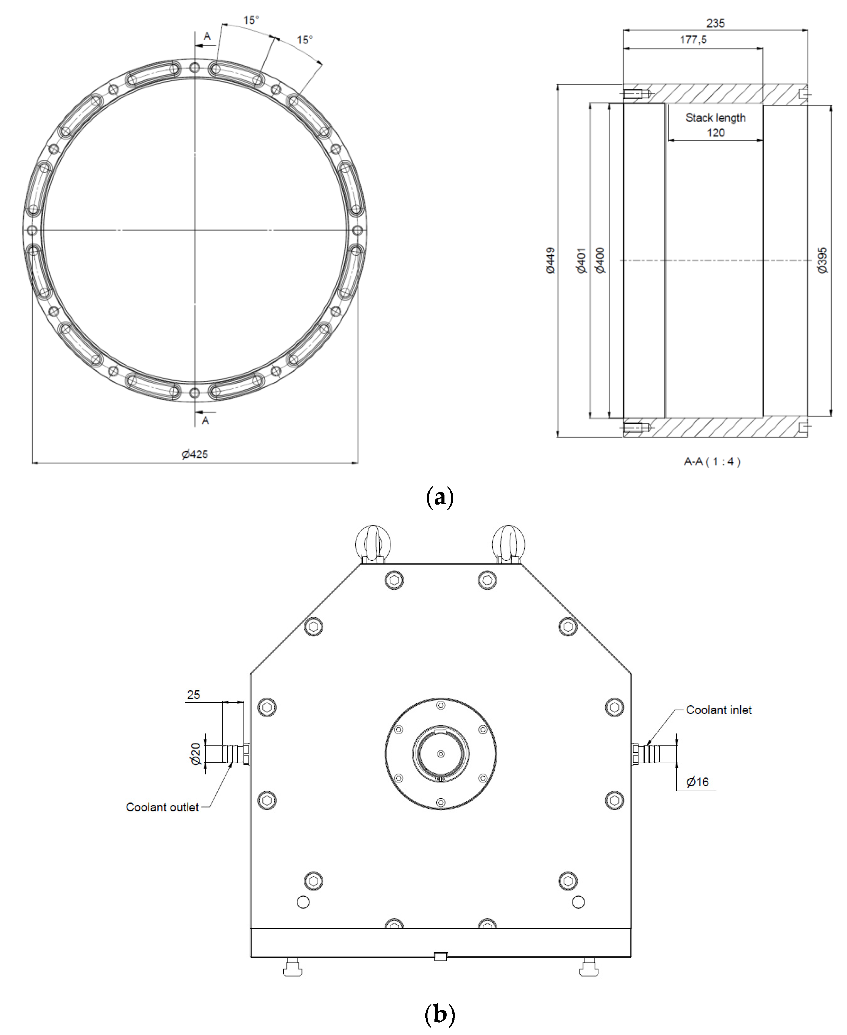
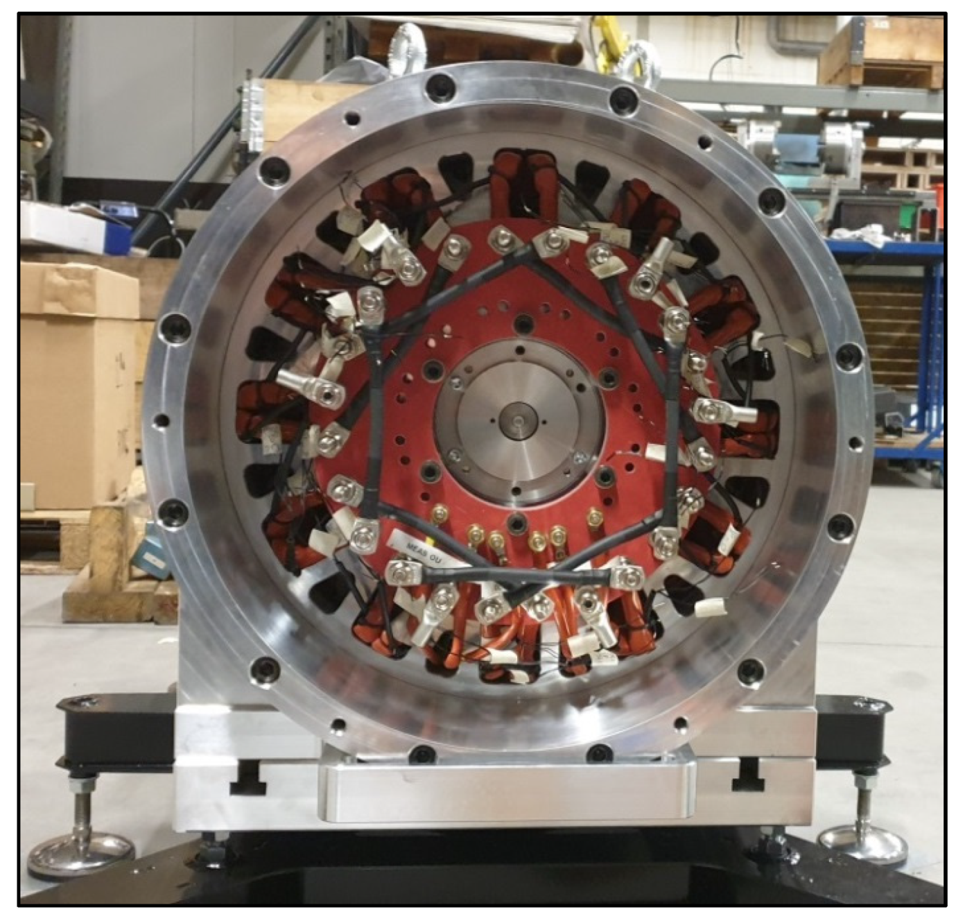
4. Prototype Construction

Figure 18 shows two CAD views of the prototype and its test bench. The test bench includes, in addition to the prototype, a drive or load machine with its power electronics [35]. The drive or load machine is an asynchronous machine associated with a mechanical gearbox for adjusting the rotation speed. This machine operates at higher speeds compared to the prototype.
As our laboratory floor could not support a load greater than 500 kg/m2, the bench included a base specifically designed to widen its seat in order to reduce the load per square meter.
Figure 19 illustrates the stator construction. Figure 19a shows the lamination sheets stack used for the construction of the stator. Figure 19b,c shows the laminations stack installed in the EDM machine (wire cutting), during and after cutting of the stator. Figure 19d shows the final stator laminated core.
Figure 20 shows the jig constructed to produce the armature coils. Figure 21 shows the construction of the base specifically designed to support the prototype test bench. A torque meter is inserted between the two machines (Figure 18b) [36]. An estimate of the mass of the prototype, from the CAD software, indicated a mass of 285 kg for the active parts. Taking into account the load limit that can be supported by the soil of the GREAH laboratory (<500 kg/m2), the base was designed to widen the base of the experimental bench (Figure 18b and Figure 21).
Figure 22 shows technical drawings of the water-cooling system specifically designed for the prototype. It consists of a water jacket which surrounds the stator. A closed loop system is provided for the water supply to this system. This water cooling allows better performance stability. It also allows boosting the performance of the prototype without deterioration risk. The prototype is also equipped with a number of thermocouples distributed in several regions of the stator (armature windings, excitation winding, and permanent magnets). The temperature measurements help to assess the efficiency of the cooling system and diagnose the thermal state of the prototype. They also allow development of a fine thermal model.
Figure 23 shows the prototype back side with stator windings and coil connections clearly visible. A zoom-in on this figure shows the thermocouples terminals.
Figure 24 shows the prototype installed on its test bench before shipping (Figure 24a) and installed at its final location with a fully operational cooling system (Figure 24b). The cooling system operates in a closed loop like that used in motor vehicles. The radiator allowing heat exchange is clearly visible in Figure 24b. The installation doesn’t include a fan, which can be added to improve the cooling efficiency. The coupling between the two machines is also visible in the fully installed test bench (Figure 24b), while it wasn’t present in the test bench before shipping (Figure 24a).

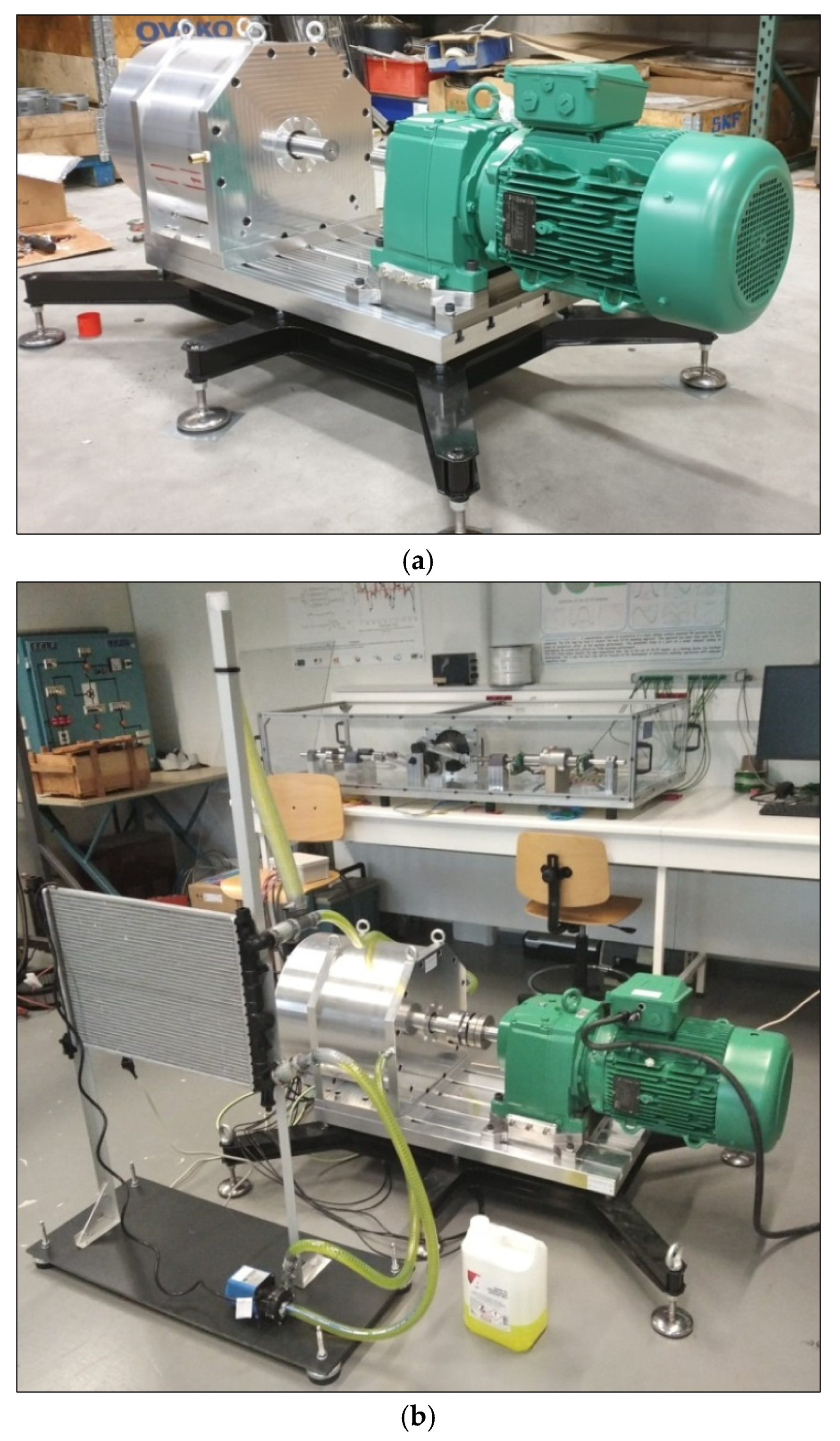
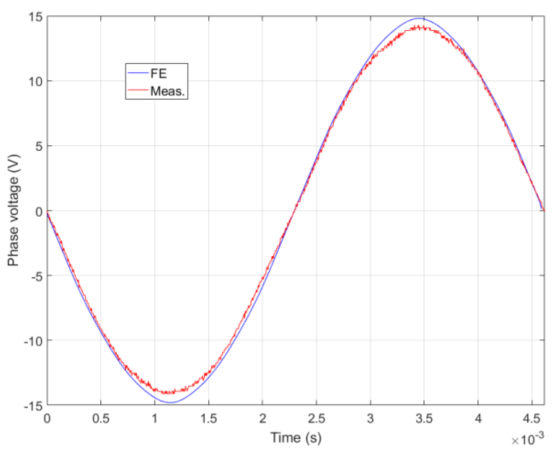
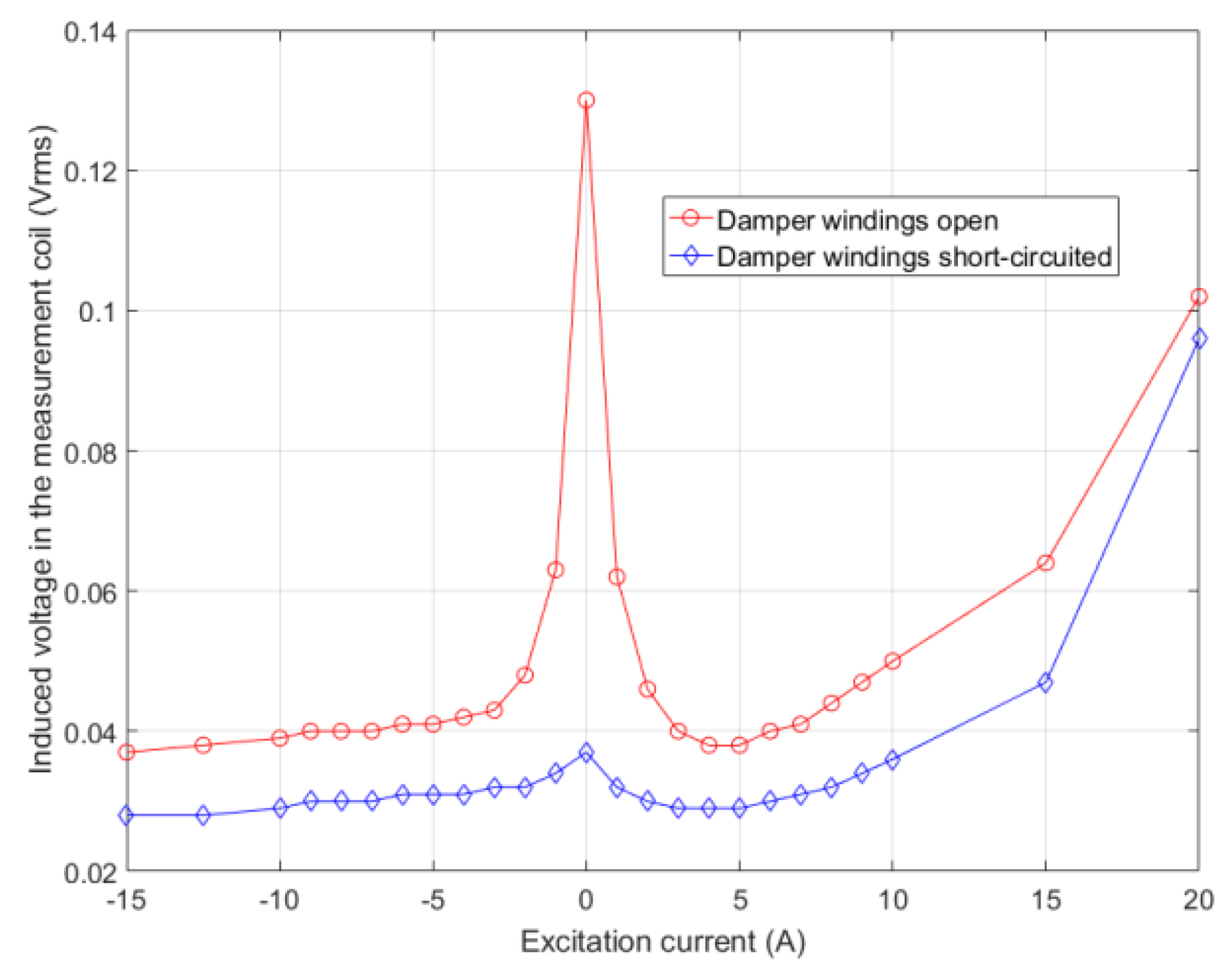
5. Experimental Study

Table 3 shows the prototype’s general characteristics and the measured resistances of the different windings and coils. The acronym DW stands for the damping winding used to reduce the voltage that may be induced in the wound field excitation coils [10,11,12,13,14,29].
The experimental study presented in this research was limited to operations under open-circuit conditions. The air-gap magnetic flux controllability was assessed, and the use of damping windings as a means for mitigating the field windings-induced voltage was confirmed. All measurements were done at a speed of 342 rpm.
Flux controllability is very important for the operation of synchronous machines in general, and even more important for hybrid excited synchronous machines specifically [37,38,39,40,41,42,43,44].
Figure 25a shows phase voltage waveforms for three values of the excitation current Iexc = −15 A, 0 A, and +15 A. The phase voltage amplitude varied with the excitation current, and, most importantly, the waveforms were close to perfect sinusoidal waveforms, as for waveforms obtained from the finite element computations. Figure 25b compares the harmonic content of the three waveforms.
Figure 26 compares the phase voltage waveform obtained from the finite element computations (FE) and that measured (Meas.) for a null excitation current Iexc = 0 A. A fairly good agreement was obtained.
Figure 27a shows the variation of phase voltage RMS value with the excitation current Iexc. It can be seen that the magnetic flux control was very effective. The air-gap flux changed with a variation of +300%, when the air gap flux was enhanced, and −50% when it was weakened with respect to the null excitation current (Iexc = 0 A). Figure 27b compares the variations of phase voltage RMS values with the excitation current obtained from finite element (FE) computations and experimental measurements (Meas.). Again, a fairly good agreement was achieved.
Compared to results presented in [29], the excitation current values imposed for enhancing the air-gap magnetic flux were pushed further. The installation of the water-cooling system reduced the risk of overheating. It should be noticed that for a value of Iexc = 35 A, the Joule loss of the excitation coils was 1347.5 W (>1 kW) if the resistance was constant; this value will increase with the temperature increase.
In order to assess the efficacy of the damper windings for the mitigation of the field windings-induced voltage, a measurement coil was wound exactly the same way as the excitation coils and the damper windings. Figure 28 compares the voltage induced in this measurements coil when the damper windings were open, and when they were short circuited. It can be seen that when short-circuited, the damper windings helped reduce the induced voltage.
Figure 29 shows induced voltage waveforms in the measurement coil for a null excitation current (Iexc = 0 A) when the damper windings are open and short-circuited. If the reduction of induced voltage using the damper windings is not sufficient, other solutions, such as rotor skewing, could be adopted [11].
It should be noticed that, while the field windings induced voltage was clearly mitigated by short-circuiting of the damper windings, the phase EMF was not affected by the damper windings being open or short-circuited.
This experimental study confirmed expected features observed from finite element computations for operations under open-circuit conditions. The experimental study is still ongoing. A torque meter [36] will be inserted between the two machines in the test bench to perform an experimental study of the machine under load conditions. Thermocouples placed in different locations of the prototype have not been exploited yet. Temperature measurements will help establish a thermal model of the prototype.

6. Conclusions

This research involved the design and production of an original generator for marine renewable energy conversion.
The generator combines interesting features, such as the use of hybrid excitation, the flux switching principle and the Vernier effect. A design analysis study confirmed the low power factor which is a characteristic of Vernier machines. However, it was found that hybrid excitation through the magnetic flux control can increase the power factor.
For renewable energy conversion systems, even if power factor improvement is interesting, it should be noticed that the primary energy source is free, and from this point of view performance of the power factor or efficiency is not as important as it could be in the case for applications such as electrical vehicles.
The experimental study of the constructed prototype showed that good flux controllability by the use of hybrid excitation. An adopted solution for the reduction of EC-induced voltage was assessed.
The experimental study is still ongoing; in particular a study under load conditions will be conducted, and the results will be provided in a future paper.

Author Contributions

Writing—review and editing, H.D., Y.A., S.H. and J.J.H.P. All authors have read and agreed to the published version of the manuscript.

Funding

The authors thank the region of Normandy (France) and the European Commission (ERDF), who supported the construction of the prototype under the grant for the NEPTUNE1 project (http://neptune-project.com/en/) (accessed on 22 September 2021).

Data Availability Statement

The data presented in this study are available on request from the corresponding author.

Conflicts of Interest

The authors declare no conflict of interest.

References

  1. ADEME. Vers un Mix Électrique 100% Renouvelable en 2050; Rapport Final. 2015. Available online: https://librairie.ademe.fr/recherche-et-innovation/2639-a-100-renewable-electricity-mix-analyses-and-optimisations.html (accessed on 22 September 2021).
  2. ENEA Consulting. Les Énergies Marines Renouvelables. Enjeux et Solutions Techniques, Mai 2012. Available online: https://www.enea-consulting.com/static/adc8934d020870e98b7823b4f3e61219/enea-les-energies-marines-renouvelables.pdf (accessed on 22 September 2021).
  3. Ministère de la Transition Écologique, Énergies Marines Renouvelables. Available online: https://www.ecologique-solidaire.gouv.fr/energies-marines-renouvelables-0 (accessed on 22 September 2021).
  4. Xie, S.J.; Xu, Z. Multitooth Magnetic Bridge Type Hybrid Excitation Magnetic Flux Switching Motor. Chinese Patent CN101834474 (A), 15 September 2010. [Google Scholar]
  5. Hoang, E.; Lécrivain, M.; Gabsi, M. A new structure of a switching flux synchronous polyphased machine with hybrid excitation. In Proceedings of the 2007 European Conference on Power Electronics and Applications, Aalborg, Denmark, 2–5 September 2007. [Google Scholar]
  6. Sulaimana, E.; Ahmada, M.Z.; Kosakab, T.; Matsui, N. Design optimization studies on high torque and high power density hybrid excitation flux switching motor for HEV. Procedia Eng. 2013, 53, 312–322. [Google Scholar] [CrossRef] [Green Version]
  7. Gaussens, B.; Hoang, E.; Lécrivain, M.; Manfe, P.; Gabsi, M. A Hybrid-excited flux-switching machine for high-speed DC-alternator applications. IEEE Trans. Ind. Electron. 2014, 61, 2976–2989. [Google Scholar] [CrossRef] [Green Version]
  8. Zhu, Z.Q.; Chen, J.T.; Pang, Y.; Howe, D.; Iwasaki, S.; Deodhar, R. Analysis of a novel multi-tooth flux-switching PM brushless AC machine for high torque direct-drive applications. IEEE Trans. Magn. 2008, 44, 4313–4316. [Google Scholar] [CrossRef]
  9. Chen, J.T.; Zhu, Z.Q.; Howe, D. Stator and rotor pole Combinations for multi-tooth flux-switching permanent-magnet brushless AC machines. IEEE Trans. Magn. 2008, 44, 4659–4667. [Google Scholar] [CrossRef]
  10. Wu, Z.; Zhu, Z.Q.; Hua, W.; Akehurst, S.; Zhu, X.; Zhang, W.; Hu, J.; Li, H.; Zhu, J. Analysis and suppression of induced voltage pulsation in DC winding of five-phase wound-field switched flux machines. IEEE Trans. Energy Convers. 2019, 34, 1890–1905. [Google Scholar] [CrossRef]
  11. Wu, Z.Z.; Zhu, Z.Q.; Wang, C.; Mipo, J.C.; Personnaz, S.; Farah, P. Reduction of open-circuit DC-winding-induced voltage in wound field switched flux machines by skewing. IEEE Trans. Ind. Electron. 2019, 66, 1715–1726. [Google Scholar] [CrossRef] [Green Version]
  12. Sun, X.; Zhu, Z.Q. Investigation of DC winding induced voltage in hybrid-excited switched-flux permanent magnet machine. IEEE Trans. Ind. Appl. 2020, 56, 3594–3603. [Google Scholar] [CrossRef]
  13. Sun, X.Y.; Zhu, Z.Q.; Wei, F.R. Voltage pulsation induced in DC field winding of different hybrid excitation switched flux machines. In Proceedings of the EEEE Energy Conversion Congress and Exposition (ECCE 2020), Detroit, MI, USA, 11–15 October 2020; pp. 1–8. [Google Scholar]
  14. Sun, X.Y.; Zhu, Z.Q.; Cai, S.; Wang, L.; Wei, F.R.; Shao, B. Influence of stator slot and rotor pole number combination on field winding induced voltage ripple in hybrid excitation switched flux machine. IEEE Trans. Energy Convers. 2021, 36, 1245–1261. [Google Scholar] [CrossRef]
  15. Tiegna, H. Contribution à la Modélisation Analytique des Machines Synchrones à Flux Axial à Aimants Permanents à Attaque Directe en vue de leur Dimensionnement. Application aux Éoliennes. Ph.D. Thesis, Université du Havre, Le Havre, France, 2013. [Google Scholar]
  16. Lee, C.H. Vernier motor and its design. IEEE Trans. Power Appar. Syst. 1963, 82, 343–349. [Google Scholar] [CrossRef]
  17. Rhodes, D.J. Assessment of Vernier motor design using generalised machine concepts. IEEE Trans. Power Appar. Syst. 1977, 96, 1346–1352. [Google Scholar] [CrossRef]
  18. Chau, K.T.; Li, Y.B.; Jiang, J.Z.; Niu, S. Design and control of a PM brushless hybrid generator for wind power application. IEEE Trans. Magn. 2006, 42, 3497–3499. [Google Scholar] [CrossRef] [Green Version]
  19. Liu, C.; Chau, K.T.; Jiang, J.Z.; Jian, L. Design of a new outer-rotor permanent magnet hybrid machine for wind power generation. IEEE Trans. Magn. 2008, 44, 1494–1497. [Google Scholar]
  20. Tiegna, H.; Amara, Y.; Barakat, G.; Dakyo, B. Overview of high power wind turbine generators. In Proceedings of the International Conference on Renewable Energy Research and Applications (ICRERA2012), Nagasaki, Japan, 11–14 November 2012; pp. 1–6. [Google Scholar]
  21. McDonald, A.S. Hybrid Excitation of Synchronous Generators for Wind Turbines. In Proceedings of the 2nd IET Renewable Power Generation Conference (RPG2013), Beihang University (BUAA), Beijing, China, 9–11 September 2013. [Google Scholar]
  22. Amuhaya, L.L.; Kamper, M.J. Design and optimisation of grid compliant variable-flux PM synchronous generator for wind turbine applications. In Proceedings of the IEEE Energy Conversion Congress and Exposition (ECCE 2015), Montreal, QC, Canada, 20–24 September 2015; pp. 1–8. [Google Scholar]
  23. Ployard, M.; Gillon, F.; Ammar, A.; Laloy, D.; Vido, L. Hybrid excitation topologies of synchronous generator for direct drive wind turbine. In Proceedings of the IEEE Energy Conversion Congress and Exposition (ECCE 2016), Milwaukee, WI, USA, 18–22 September 2016; pp. 1–7. [Google Scholar]
  24. Wang, Q.; Niu, S. Overview of flux-controllable machines: Electrically excited machines, hybrid excited machines and memory machines. Renew. Sustain. Energy Rev. 2017, 68, 475–491. [Google Scholar] [CrossRef]
  25. Ching, T.W.; Chau, K.T.; Li, W. Power factor improvement of a linear Vernier permanent-magnet machine using auxiliary DC field excitation. IEEE Trans. Magn. 2016, 52, vg8204804. [Google Scholar] [CrossRef]
  26. Beik, O.; Schofield, N. High-voltage hybrid generator and conversion system for wind turbine applications. IEEE Trans. Ind. Electron. 2018, 65, 3220–3229. [Google Scholar] [CrossRef] [Green Version]
  27. Zhao, X.; Niu, S.; Fu, W. Sensitivity analysis and design optimization of a new hybrid-excited dual-PM generator with relieving-DC-saturation structure for stand-alone wind power generation. IEEE Trans. Magn. 2020, 56, 7504105. [Google Scholar] [CrossRef]
  28. Available online: https://greah.univ-lehavre.fr/spip.php?article215 (accessed on 22 September 2021).
  29. Hlioui, S.; Gabsi, M.; Ben Ahmed, H.; Barakat, G.; Amara, Y.; Chabour, F.; Paulides, J.J.H. Hybrid excited synchronous machines. IEEE Trans. Magn. 2021. [Google Scholar] [CrossRef]
  30. CEDRAT. User Guide Flux® 11.2. New Features. 2013. Available online: http://www.tianyuantech.com/download/flux112.pdf (accessed on 22 September 2021).
  31. Atallah, K.; Howe, D.; Mellor, P.H.; Stone, D.A. Rotor loss in permanent-magnet brushless AC machines. IEEE Trans. Ind. Appl. 2000, 36, 1612–1618. [Google Scholar]
  32. Frias, A.; Kedous-Lebouc, A.; Chillet, C.; Albert, L.; Calegari, L.; Messal, O. Loss minimization of an electrical vehicle machine considering its control and iron losses. IEEE Trans. Magn. 2016, 52, 8102904. [Google Scholar] [CrossRef]
  33. Ede, J.D.; Atallah, K.; Jewell, G.W.; Wang, J.B.; Howe, D. Effect of axial segmentation of permanent magnets on rotor loss in modular permanent-magnet brushless machines. IEEE Trans. Ind. Appl. 2007, 43, 1207–1213. [Google Scholar] [CrossRef]
  34. Nair, S.S.; Wang, J.; Chin, R.; Chen, L.; Sun, T. Analytical prediction of 3-D magnet eddy current losses in surface mounted PM machines accounting slotting effect. IEEE Trans. Energy Convers. 2017, 32, 414–423. [Google Scholar] [CrossRef]
  35. Leroy-Somer (Nidec). Manuel de l’Électromécanique. Available online: https://www.leroy-somer.com/documentation_pdf/5181_fr.pdf (accessed on 22 September 2021).
  36. HBM. T40B: Mesure de Couple de 50 Nm à 10k Nm. Available online: https://www.hbm.com/fr/3004/t40b-torque-transducer-with-a-rotational-speed-measuring-system/ (accessed on 22 September 2021).
  37. Nedjar, B.; Hlioui, S.; Amara, Y.; Vido, L.; Gabsi, M.; Lécrivain, M. A new parallel double excitation synchronous machine. IEEE Trans. Magn. 2011, 47, 2252–2260. [Google Scholar] [CrossRef]
  38. Yamazaki, K.; Nishioka, K.; Shima, K.; Fukami, T.; Shirai, K. Estimation of assist efffects by additional permanent magnets in salient-pole synchronous generators. IEEE Trans. Ind. Electron. 2012, 59, 2515–2523. [Google Scholar] [CrossRef]
  39. Kamiev, K.; Nerg, J.; Pyrhönen, J.; Zaboin, V.; Hrabovcova, V.; Rafajdus, P. Hybrid excitation synchronous generators for island operation. IET Electr. Power Appl. 2012, 6, 1–11. [Google Scholar] [CrossRef]
  40. Kamiev, K.; Pyrhönen, J.; Nerg, J.; Zaboin, V.; Tapia, J. Modeling and testing of an armature-reaction-compensated (PM) synchronous generator. IEEE Trans. Energy Convers. 2013, 28, 849–859. [Google Scholar] [CrossRef]
  41. Kamiev, K. Design and Testing of Armature-Reaction Compensated Permanent Magnet Synchronous Generator for Island Operation. Ph.D. Thesis, Lappeenranta University of Technology, Lappeenranta, Finland, 2013. [Google Scholar]
  42. Kamiev, K.; Nerg, J.; Pyrhönen, J.; Zaboin, V.; Tapia, J. Feasibility of an armature-reaction-compensated permanent-magnet synchronous generator in island operation. IEEE Trans. Ind. Electron. 2014, 61, 5057–5058. [Google Scholar] [CrossRef] [Green Version]
  43. Kamiev, K.; Parviainen, A.; Pyrhönen, J. Hybrid excitation synchronous generators for small hydropower plants. In Proceedings of the 22nd International Conference Electrical Machines (ICEM 2016), Lausanne, Switzerland, 4–7 September 2016. [Google Scholar]
  44. Ammar, A.; Berbecea, A.C.; Gillon, F.; Brochet, P. Influence of the ratio of hybridization on the performances of synchronous generator with hybrid excitation. In Proceedings of the 20th International Conference on Electrical Machines (ICEM 2012), Marseille, France, 2–5 September 2012. [Google Scholar]
Figure 1. Studied machine structure: (a) 3D view; (b) face view showing the magnetic field sources.
Energies 14 06060 g001
Figure 2. Dimensions of the studied machine (Courtesy of AE-Group, The Netherlands): (a) 2D axial cut; (b) zoom on zone A; (c) zoom on zone B.
Energies 14 06060 g002
Figure 3. Armature and excitation field windings distributions.
Energies 14 06060 g003
Figure 4. 2D FE model: (a) 2D Mesh of studied domain; (b) zoom on air-gap region.
Energies 14 06060 g004
Figure 5. Mesh evaluation in Flux2D.
Energies 14 06060 g005
Figure 6. B(H) curve of the material used for the ferromagnetic parts (M330-35A).
Energies 14 06060 g006
Figure 7. EMF waveforms comparison for WF and HE versions: (a) EMF waveforms; (b) harmonic contents.
Energies 14 06060 g007
Figure 8. EMF waveforms comparison for different excitation current values: (a) EMF waveforms; (b) harmonic contents.
Energies 14 06060 g008
Figure 9. Cogging torque waveforms for different excitation current values.
Energies 14 06060 g009
Figure 10. Load torque waveforms for JArm. = 5 A/mm2 (phase armature current in phase with the phase EMF).
Energies 14 06060 g010
Figure 11. Average load torque variation with angle ψ.
Energies 14 06060 g011
Figure 12. Load torque variations with different values of JArm.: (a) load torque waveforms; (b) average torque variation.
Energies 14 06060 g012
Figure 13. Load torque variations with different values of JArm.: (a) load torque waveforms; (b) average torque variation.
Energies 14 06060 g013
Figure 14. Magnetic flux density distribution (the scale is in Tesla) and flux lines.
Energies 14 06060 g014
Figure 15. Phase voltage and armature current of a given phase: (a) phase voltage; (b) armature current.
Energies 14 06060 g015
Figure 16. Harmonic content of the phase voltage.
Energies 14 06060 g016
Figure 17. Load torque for Jexc = 10 A/mm2, JArm. = 2.75 A/mm2 and ψ = 0°.
Energies 14 06060 g017
Figure 18. CAD views of the realized prototype (Courtesy of AE-Group, The Netherlands): (a) 3D cutaway view of the prototype; (b) prototype test bench.
Energies 14 06060 g018
Figure 19. Stator construction (Courtesy of AE-Group, The Netherlands): (a) laminations sheets stack; (b) laminations stack during machining; (c) laminations stack after machining; (d) final stator laminated core.
Energies 14 06060 g019
Figure 20. Jig for production of the armature windings (Courtesy of AE-Group, The Netherlands): (a) jig; (b) production of an armature coil using the jig.
Energies 14 06060 g020
Figure 21. Production of the test bench base (Courtesy of AE-Group, The Netherlands).
Energies 14 06060 g021
Figure 22. Water cooling system of the prototype (Courtesy of AE-Group, The Netherlands): (a) technical views of the water jacket; (b) view of the prototype with the water inlet and outlet pipes.
Energies 14 06060 g022
Figure 23. Prototype back side with stator windings and coil connections [29] (Courtesy of AE-Group, The Netherlands).
Energies 14 06060 g023
Figure 24. Prototype on its test bench: (a) test bench before shipping (Courtesy of AE-Group, The Netherlands); (b) fully operational test bench installed at its final location.
Energies 14 06060 g024
Figure 25. Measured phase voltage waveforms for Iexc = −15 A, 0 A, and +15 A: (a) waveforms; (b) comparison of harmonic content.
Energies 14 06060 g025
Figure 26. Comparison of FE computed and measured phase voltage waveforms for Iexc = 0 A.
Energies 14 06060 g026
Figure 27. Phase voltage RMS value variation with excitation current (flux control capability): (a) measured curve; (b) comparison of finite element curve (FE) and measured curve (Meas.).
Energies 14 06060 g027
Figure 28. Comparison of induced voltage in the measurement coil for damper windings open and short circuited for different excitation currents.
Energies 14 06060 g028
Figure 29. Induced voltage in the measurement coil for Iexc = 0 A.
Energies 14 06060 g029
Table 1. Prototype’s general characteristics.
QuantityValue
Nominal power (kW)10
Nominal rotation speed (rpm)300
External radius (mm)200
Active length (mm)120
Air-gap thickness (mm)1
PM characteristics (Br (T), μr)1.25, 1
Number of turns of armature windings9
Number of turns of excitation coil31
Table 2. Losses balance.
OperationF1F2
Armature windings Joule loss (W)480145
Excitation coil Joule loss (W)165659
Iron loss (W)843664
PM eddy current loss (W)126141
Total loss (PLoss) (W)/Efficiency η (%)2749/731509/85
Table 3. Constructed prototype’s general characteristics.
QuantityValueQuantityValue
Nominal power (kW)10Mass of the stator iron core (kg)76.5
Nominal speed (rpm)300Mass of the rotor iron core (kg)73.5
External radius (mm)200Mass of the copper (Kg)128
Rotor outer radius (mm)120Armature windings (AW) number of turns9
Active length (mm)120Excitation coil (EC) number of turns31
Air-gap thickness (mm)1Damping winding (DW) number of turns4
Number of rotor teeth38AW resistance (at room temperature) (Ω)0.1
PM typeNdFeBEC resistance (at room temperature) (Ω)1.1
Mass of the PM (kg)6.5DW resistance (at room temperature) (Ω)0.25
Publisher’s Note: MDPI stays neutral with regard to jurisdictional claims in published maps and institutional affiliations.

