Article

Aspects of Selecting Appropriate Conveyor Belt Strength

by
Dariusz Woźniak
* and
Monika Hardygóra
Faculty of Geoengineering, Mining and Geology, Wroclaw University of Science and Technology, Na Grobli 15 St., 50-421 Wrocław, Poland
*
Author to whom correspondence should be addressed.
Energies 2021, 14(19), 6018; https://doi.org/10.3390/en14196018
Submission received: 31 July 2021 / Revised: 13 September 2021 / Accepted: 17 September 2021 / Published: 22 September 2021
(This article belongs to the Special Issue Energy-Efficiency of Conveyor Belts in Raw Materials Industry)

Abstract

:
Breaks in the so-called “continuous” (unspliced) belt sections, and not in the spliced areas, are infrequent but do happen in practice. This article presents some aspects, which may account for such breaks in conveyor belts. It indicates the so-called “sensitive points” in design, especially in the transition section of the conveyor belt and in identifying the actual strength of the belt. The presented results include the influence of the width of a belt specimen on the identified belt tensile strength. An increase in the specimen width entails a decrease in the belt strength. The research involved develops a universal theoretical model of the belt on a transition section of a troughed conveyor in which, in the case of steel-cord belts, the belt is composed of cords and layers of rubber, and in the case of a textile belt, of narrow strips. The article also describes geometrical forces in the transition section of the belt and an illustrative analysis of loads acting on the belt. Attention was also devoted to the influence of the belt type on the non-uniform character of loads in the transition section of the conveyor. A replacement of a conveyor belt with a belt having different elastic properties may increase the non-uniformity of belt loads in the transition section of the conveyor, even by 100%.

1. Introduction

Belt conveyors are an indispensable means of transport in a number of industry branches–most importantly, in the extraction industry, in smelting and coking plants, and in power plants, but also in the chemical industry, in civil engineering and in agriculture. Belt conveyors are also vital in shipping ports, where they are used to transport, load and unload bulk materials. In the extraction industry, conveyor belt transportation systems are used both in surface and in underground mining. The belt is the most expensive part of the belt conveyor. Its purchase cost represents 50–60% of the cost of the entire conveyor. The belt is also the least durable element of the conveyor. The belt is, thus, an element crucial for the effective and reliable operation of the conveyor and significantly influences the transportation costs [1].
The selection of a conveyor belt capable of performing a particular transportation task when installed on a belt conveyor is primarily informed by the tensile strength of this belt. It is intended to ensure that the forces in the operating belt will not lead to it breaking, i.e., to an event that is dangerous to both the personnel and to the conveyor. Typically, in the belt conveyor design process, the values of safety factors are empirically identified [2,3].
The belt is installed on the conveyor in a closed loop. The type of the splices used in the belt depends mainly on the design of the belt core. In most cases, splices have the lowest strength in the entire belt. Nevertheless, occasionally, breaks develop not in the area of the splice, but in the so-called “continuous” belt section. Reasons for such events are an object of investigation. This article analyzes two aspects, which deserve attention when selecting an appropriate belt to match the conveyor—the non-uniformity of belt loads in the transition section of the conveyor, where the belt changes its shape from troughed into flat to enter the pulley, and the influence of the specimen width on the belt strength. Aspects related to belt damage during its operation (punctures, cuts, etc.) are here omitted, although obviously, they are important and monitored by conveyor operators [4,5,6,7]. The analysis here presented is supported by many years of experience gained as a result of testing conveyor belts at the Belt Conveying Laboratory, Wroclaw University of Science and Technology (WUST).
When implementing a particular transportation task, the force levels in the belt and the power of the drive system are identified after calculating conveyor resistances to motion and the minimal tensile force required to ensure frictive engagement between the pulley and the belt. Köken et al. reviewed and compared leading methods used in belt conveyor calculations [8].
In the transition section of the conveyor, the outermost load-carrying elements of the core accept additional tensile loads, while the loads in the central part of the belt decrease. In the existing calculation methods, the length of the transition section should be defined in such a manner that the non-uniformity of belt loads is reduced and unit forces in the belt are not exceeded. That CEMA method [9] defines the minimum length of the transition section depending on the geometrical parameters of the section and differentiates between only two groups of belts: with steel cord and with textile core. Importantly, however, textile core belts may significantly differ with respect to their elastic properties and show different reactions in response to geometry changes of the transition section. The Fenner–Dunlop method has a similar approach to the identification of the transition section [10]. In the DIN method [11], the length of the transition section is calculated on the basis of simplified relationships, but with allowance for the longitudinal elastic modulus of the belt.
Accurate identification of the stress state in the belt along the transition section requires a model that allows for not only the longitudinal elastic modulus of the belt, but also for the interactions between the adjacent cables or straps in the belt. Oehmen [12] and Hager and Tappeiner [13] focused in their research on identifying the strain state in the belt along the transition section. Schmandra [14] presented a general theoretical model of a steel cord belt, allowing for the interactions between the adjacent cables. The literature also mentions implementations of the finite element method in the modeling of a belt along the transition section of the conveyor [15,16,17,18]. The analysis in [17] focused on the influence of the elastic modulus in the longitudinal and transverse directions of the belt-on-belt load non-uniformity.
The research here presented involves developing a universal theoretical model of the belt along a transition section of a conveyor in which, in the case of steel-cord belts, the belt is composed of cords and layers of rubber, and in the case of a textile belt, of narrow strips. An analysis was performed into how the non-uniformity of the belt load along the transition section of the conveyor will change if belts with different cores are used. The research also involved tests of the influence of the specimen width on the belt tensile strength. The literature does not mention any results of similar previous studies.

2. Materials and Methods

2.1. Selection of Belt Strength

In the design phase of a belt conveyor, the selection of a conveyor belt typically consists of selecting the material and core design, and also in deciding on the thickness and the material of the protective covers. An optimal design of the belt core is achieved on the basis of a detailed technical and economic analysis, which allows for such factors as follows [1]:
  • Belt nominal strength in relation to the forces in the belt on an operating conveyor;
  • Conveyor length;
  • Potential for splicing belt sections;
  • Fatigue life of splices;
  • Loads in the material feeding points;
  • Belt operating conditions, fire and explosion protection;
  • Properties of the transported material (size of the lumps, their angularity, temperature, etc.).
Nominal strength of a textile-core belt is identified, according to the following relationship [3]:
K n S r   m a x 1000 B · k e · k b
where:
  • Kn—nominal strength, kN/m or N/mm;
  • B—belt width, m;
  • Srmax—maximum strength in the belt during start-up, N;
  • ke—safety factor allowing for the operating conditions;
  • kb—safety factor allowing for lower strength in the splice.
With the values of individual factors assumed in accordance with the recommendations found in the literature [2,3,11], the total safety factor in relationship to the forces in steady motion for textile belts will remain within the range of 9 ÷ 12. In terms of design standards, this level of safety is high. When designing long, high-capacity conveyors with steel-cord belts, proposals are made to lower this safety standard or to use the so-called operational belt safety factor [19]. In the design phase, however, note should be made that as the belt moves on the conveyor, it is subjected to such states as those induced by horizontal and vertical curves or transition sections, which entail significant momentary variations of specific forces in the belt cross-section. This phenomenon is related to the fact that individual threads in the warp of the belt core move along different paths, due to the geometrical forces existing in the belt.
The above applies particularly to the transition section of a conveyor in which the belt experiences the greatest forces, as is the case mostly in the section of belt transition from a troughed shape into a flat shape, at a point in which the belt enters the drive pulley. The difference between the maximum and the minimum specific force in the belt cross-section on the pulley depends on the geometry of the system and on the dynamic modulus of the belt [12,13,14,15,16,17]. For long conveyors and for two-parameter belt models, this modulus is assumed to be equal to the longitudinal modulus of elasticity. Therefore, designs of the geometry of the transition section are based on the knowledge of the elastic properties of the belt operated on the conveyor. Unfortunately, belt manufacturers rarely include the longitudinal modulus of elasticity in their product specifications. This modulus is identified in laboratory tests, according to the method described in ISO 9856. Research works performed in the Belt Conveying Laboratory at WUST include identifying elastic properties of conveyor belts with cores of different designs. Table 1 presents illustrative values of the elastic modulus for conveyor belts.
Longitudinal modulus of elasticity depends on the strength of the belt, but most importantly on the fabric in the carcass, its weave and core structure. Belts of a similar strength type may have significantly different elastic moduli, e.g., the modulus in a multi-ply polyamide belt with plain-woven plies is two-fold lower than in a belt with a solid-woven carcass and five-fold lower than in an aramid belt with a straight warp carcass. Steel-cord belts have the highest elastic modulus. A higher modulus in the belt with identical geometrical forces in the transition section will mean a greater variety of specific forces in the belt cross-section. Replacement of a conveyor belt with a belt having a different design but identical geometrical parameters of the transition section may, thus, lead to exceeding the limit forces in the belt. This issue was analyzed with the use of a dedicated theoretical model of the belt in the transition section of the conveyor (Section 3).

2.2. Verification of Actual Belt Strength

Conveyor belt strength is identified in laboratory pull tests, in accordance with the method described in ISO 283. This test is commonly performed as part of belt quality control procedures in laboratories at manufacturing plants. Due to technical limitations of the test equipment, the belt strength is identified by testing specimens having a width significantly smaller than the width of the entire belt installed on the conveyor. This fact leads to a question of whether the strength tested on a small specimen corresponds to the strength of the belt having a full width. For this reason, tests were performed into how the test scale influences the test result. The tests at the Belt Conveying Laboratory, WUST, involved identifying tensile strength for the same belt, but for specimens having different widths in the reduced area. Due to the technical capabilities of the test machine, the maximum width of the tested belt specimen was 50 mm. All samples were paddle-shaped and prepared with the same radius R = 560 mm—only the width in the reduced area changed. Five different specimen widths were used: 20, 25, 30, 40 and 50 mm. The tests were performed for a 3-ply belt with polyamide carcass (belt A) and for a 4-ply belt with a polyester–polyamide carcass (belt B). The results of the tests are shown in Figure 1. In the case of both belts, a decrease in the tensile strength was observed to accompany an increase in the specimen width. Whether this phenomenon results from the test method—the specimen shape, change in its width to curve radius ratio, and change in its width to length ratio—or from the strength characteristics of such multi-layer and multi-fiber structures as belts, required further investigations. The tests indicated that an increase in the specimen width entails a decrease in its elongation at break (Figure 2); this fact can be attributed to the strength characteristics of textile belts. If the strength tests are performed for a single thread, the strength of the entire structure comprising such threads is not equal to the multiple of the single thread. This is because each thread in such a structure may have a different preliminary load due to, for example, the preliminary tension, weave, or thermal shrinkage that occurs during the belt production process. In such a case, the break is a gradual process: the threads with the highest preload will break first, followed by the remaining threads. As a consequence, the strength will be lower than the multiple of the strength of a single thread.
The tests demonstrated changes in the belt tensile strength, which depend on the specimen width and which can be described with a quadratic function. If assumed that the changes result solely from the strength characteristics of such structures as a conveyor belt, and not from the test method or from other reasons, and if also assumed that the trend identified in the test is constant, then the actual strength of a 1200 mm wide belt may be estimated at 60% of the strength measured in standardized tests. As the safety factor used in the process of selecting belt strengths is relatively high (above 9), the above estimation seems appropriate. This aspect is nevertheless important when using belts of greater widths, or when designing curve geometries along the route and the conveyor transition section, especially in the zone of the highest specific forces in the belt.

3. Theoretical Model of the Belt on the Transition Section of the Conveyor

3.1. Preliminary Assumptions behind the Model

  • The belt is considered as a multi-strip flat tension member, globally carrying only longitudinal loads. In the case of a steel-cord belt, the strip is a steel cord with the surrounding rubber, and in the case of a textile belt, the strip is composed of a number of warp threads.
  • The strips are modeled as linear elastic elements.
  • The rubber that connects the adjacent cords or weft threads is responsible for the mutual interaction of the adjacent strips, which is modeled with the use of the artificial modulus of non-dilatational strain.
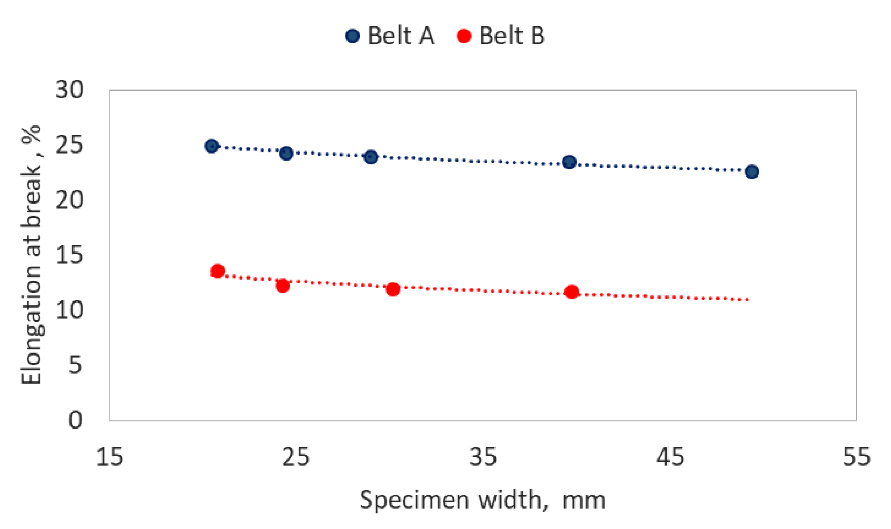
  • The longitudinal rigidity of the strips and the artificial modulus of non-dilatational strain between the strips are determined on the basis of laboratory tests.
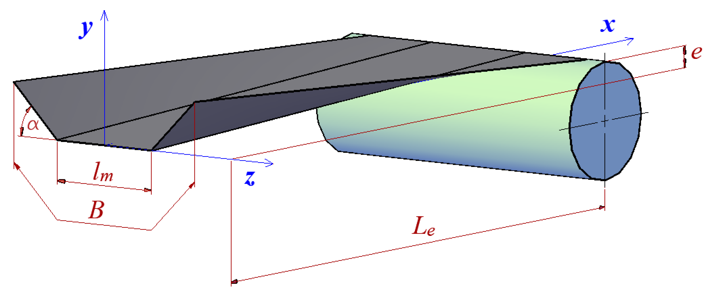
  • The considered belt section has a length Le + K, where Le is the length of the transition section, and K is the length of the section of influence, in which the stresses equalize.
  • The belt is subjected to tension at a constant force FN.
  • No external loads are observed along the length Le of the transition section (i.e., motion resistances are absent, and the impact of gravity is negligible), which means that in each cross-section, the sum of forces in the strips is equal to the tensile force FN. The influence of the pulley is also negligible.
  • The rubber between the cables is not deformed in the lateral direction, and therefore, the distances between the cable axes (the cable pitch) are constant. This assumption allows the equation to be solved as a system of coplanar forces.
  • Calculations are performed for a half of the belt, from the edge to its axis of symmetry (the system is assumed to be symmetrical).

3.2. Geometrical Forces in the Transition Section of the Conveyor

The basis for a model thus formulated is to determine elongations for individual strips. These result from the path traveled by each strip when the belt transitions from a troughed cross-section into a flat cross-section on the pulley. Consideration is paid to the path traveled by steel cords (in the case of steel-cord belts) or to the path of the longitudinal axes of the analyzed strips (in the case of textile belts). The issue was analytically described with the use of the coordinate system shown in Figure 3.
The length of each cable Δ l   (each longitudinal axis of the strip) is determined as the Euclidean distance between the position of the cable at the beginning of the coordinate system (x = 0) and the position of the cable at the end of the transition section (x = Le).
Δ l = Δ x 2 + Δ y 2 + Δ z 2
Cable elongation Δ u in the transition section is the following:
Δ u = Δ l L e
At the beginning of the transition section, the belt cross-section is troughed, and the coordinate x = 0 . The positions of individual cables may be described with the following relationships:
-
For z 1 2 l m
z i = i · t
y i = 0
-
For z > 1 2 l m
z i = 1 2 l m + ( i · t 1 2 l m ) cos α
y i = ( z i 1 2 l m ) tan α
where:
i—cable number i = 1 ÷ n ;
n—number of cables across the half of the belt width;
lm—length of the central part of the belt trough, mm;
t—cable pitch (strip width), mm;
α—trough angle.
At the end of the transition section, the belt cross-section is flat, and the coordinate x = L e . The positions of individual cables may be described with the following relationships:
z i = i · t
y i = e
where:
  • e—height difference between the contour of the pulley coat and the central part of the trough, mm.
The belt displacement area determined from the model based only on the geometrical relationships (Figure 4) is a certain simplification of the actual condition, but it is sufficient to analyze the behavior of various belt core structures along the transition section of the conveyor.

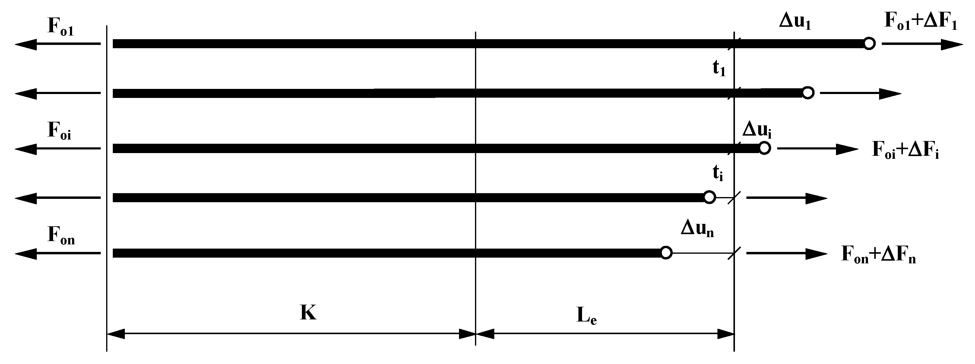
3.3. Theoretical Basis for the Belt Model in the Transition Section

The model reflects half of the belt, having a length equal to the length of the transition section Le and the length of the section of influence K. The symmetrical half of the belt core is composed of n cables. The initial load state in the belt core is due to the FN force in the belt. The cables form a parallel structure, i.e., each cable in the core will be elongated by an identical initial distance uo. Thus, the initial force in the ith cord Foi is the following:
F o i = u o l ( E A ) i
from the condition of the equilibrium of forces as follows:
F N = 2 i = 1 n F o i
where:
  • (EA)i—longitudinal rigidity of the ith cable/strip, N;
  • l—length of the analyzed belt section, mm.
On the other hand, the forces from the geometrical input related to the transition section of the conveyor in which cable elongations have a non-uniform distribution (Figure 5) were identified on the basis of the elastic strain energy of a coplanar system of parallel cables and rubber [20].
An increase in the elastic strain energy Δ E is accounted for by an increase in the elastic strain energy in the cable Δ E l and by an increase in the elastic strain energy in the rubber Δ E g .
Δ E = Δ E l + Δ E g
Partial derivative of energy with respect to force provides the elongation as follows:
Δ E Δ F = Δ u
The analysis of steel-cord belt models [14] indicates that differential equations describing the variability of forces in the cords should be solved by combining hyperbolic functions, which is the effect of the character of differential equations. The development of these functions into Taylor series gives polynomials with strongly decreasing successive terms.
Only the first two terms may be accepted with a satisfactory accuracy of several percent [3], and therefore, the equation describing the variability of forces in a single cord may be simplified to a quadratic function. This assumption is confirmed by the results of load tests performed for cords in the areas of the transition sections [13]. Due to the interaction between adjacent cables through the rubber layer (and in the case of textile belts, through the rubber and the weft threads), the force in any cable changes in accordance with the following relationship:
F ( x ) = F o ( 1 + a x 2 )
for x = L e + K = L as follows:
F k = F o ( 1 + a L 2 )
where:
  • Fo—initial force, N;
  • Fk—final force, N.
Thus,
a = 1 L 2 ( F k F o 1 )
then we have the following:
F ( x ) = F o + F k x 2 L 2 F o x 2 L 2
Increase in elastic strain energy in the cable is expressed with the following equation:
Δ E l = 1 2 ( E A ) 0 L F 2 ( x ) d x = 1 2 ( E A ) F o 2 0 L ( 1 + a x 2 ) 2 d x
Δ E l = 1 2 ( E A ) F o 2 ( L + 2 3 a L 3 + 1 5 a 2 L 5 )
then, the partial derivative of elastic strain energy in the cable with respect to force is as follows:
Δ E l F k = Δ E l a · a F k
Δ E l F k = L ( E A ) ( 3 15 F k + 2 15 F o )
The next step consists of determining the elastic strain energy and derivative for the strip of rubber between the cables.
d E g = 1 2 Δ u ( x ) τ h t · d x
where:
  • ht—belt thickness, mm.
Tangential stresses τ are:
τ = γ G * = Δ u ( x ) t G *
where:
  • G * —artificial modulus of non-dilatational strain determined in laboratory tests, N/mm2;
  • t—cable pitch, mm.
Then,
Δ E g = 1 2 · h t G * t 0 x Δ u ( x ) 2   d x
Partial derivative of the energy in the ith rubber strip with respect to the force in the ith cable is as follows:
Δ E g i F i = h t G * t 0 x Δ u ( x ) · · u ( x ) F i   d x
Partial derivative of energy with respect to force for the ith cable is as follows:
Δ E i F i = Δ E l i F i + Δ E g i F i + Δ E g i 1 F i
Relationships (21), (25), (13) provide a system of n equations of the following type:
A i 1 · F i 1 + A i · F i + A i + 1 · F i + 1 + C i = 0
The matrix Gauss method allows a solution to the system of equations in the form of the vector of forces Fi in the cords.

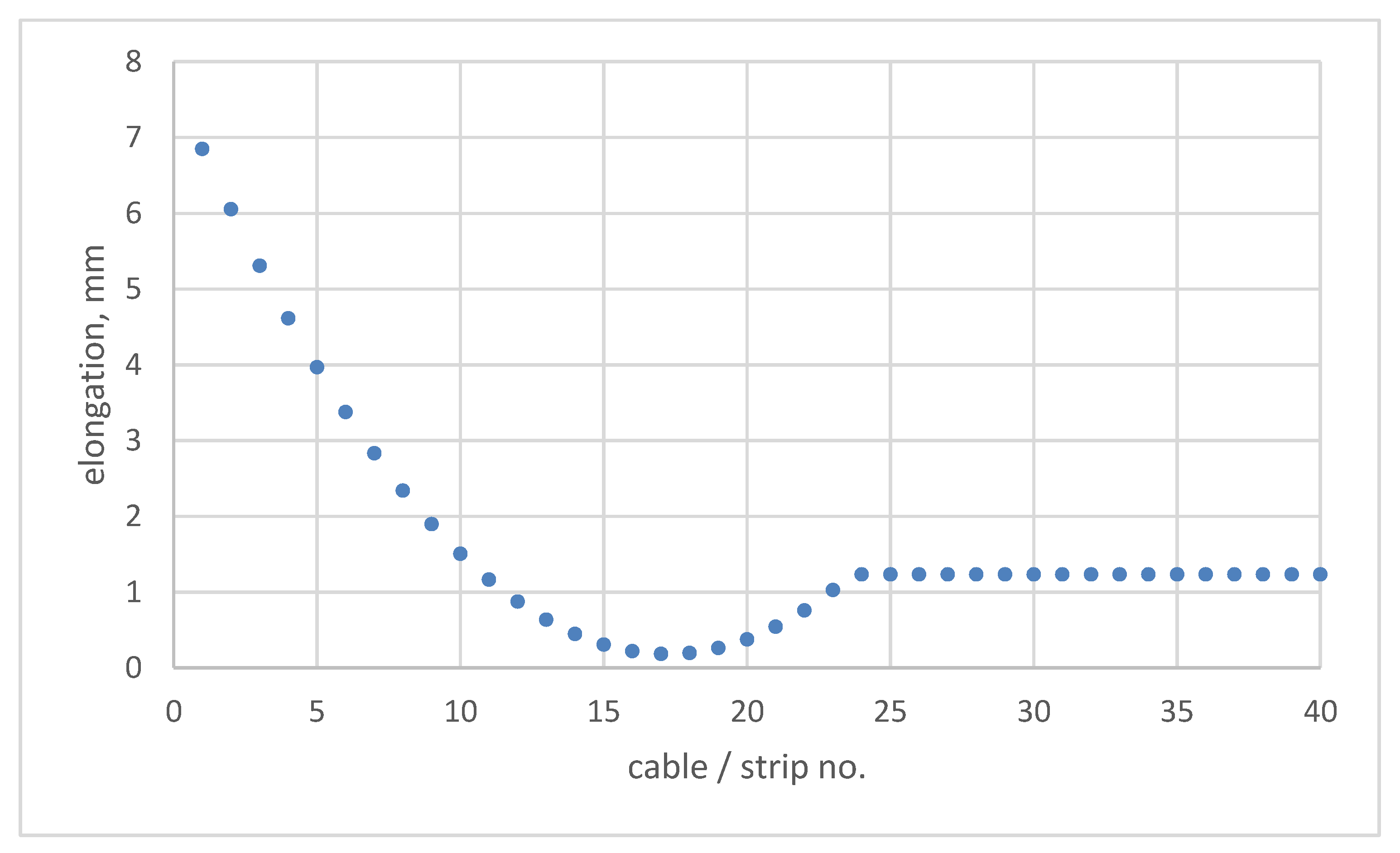
4. Analysis of Loads on the Belt in the Region of the Transition Section in Troughed Conveyors

An analysis was conducted of loads acting on the belt in the transition section of a belt conveyor and of the influence of the belt type on the level of such loads involved for performing calculations for five conveyor belts having a strength of 2000 kN/m and various core designs. The calculations were performed for a steel-cord ST belt, an aramid core DP belt, a solid woven PWG belt, as well as for a multi-ply polyester–polyamide EP belt and a polyamide PP belt. Identical geometrical parameters of the transition section were used in each case.
The calculations were based on the physical and mechanical belt parameters identified in laboratory tests [21,22]: longitudinal modulus of elasticity E and artificial modulus of non-dilatational strain G*. The calculations provided the distribution of loads on the cables/strips with respect to the belt width in the region of the pulley. Figure 6 shows force increments in the belt cables/strips in the cross section of the area where the belt enters the pulley, the increments being the effect of deformations in the transition section. The graph includes half of the belt thickness from the edge to the center.
In the analyzed cases, the absolute values of forces in individual belts are not important, as they result from the geometrical parameters of the transition section and its influence zone, as well as from the initial force in the belt, as assumed in the calculations. The behavior of different belts in the transition section can be reliably evaluated by observing the non-uniform character of loads acting on individual cables/strips in the belt. This non-uniform character of loads can be measured as a difference between the maximum and the minimum increment of force in the belt Δ F m a x Δ F m i n . The load non-uniformity indicators thus obtained are shown in Table 2.
The resulting load non-uniformity indicators are significantly different for the analyzed belts. As compared to the multiply polyamide belt, the load non-uniformity indicators for the polyester–polyamide belt are 50% higher, and for the solid woven, aramid core and steel-cord belts, it is two-fold, three-fold and five-fold higher, respectively. Data presented in manuals provided by the most prominent conveyor belt manufacturers and in standards define relationships for adjusting the parameters of the transition section and the belt, which are based on simplified equations allowing for the geometry and the longitudinal modulus of elasticity of the belt, but not for the interactions between the adjacent cables/strips. The approach is different solely in the case of designing the transition section for a steel-cord belt and for the remaining group of textile belts. Importantly, however, when replacing a worn belt, each decision to change the belt type should be preceded by an analysis aiding the selection of the geometrical parameters of the transition section in the belt conveyor. This is of particular importance in the location where the greatest longitudinal forces are observed in the belt, i.e., typically in the drive pulley. In the case when the operator decides to install a belt having different elastic properties but without modifying the geometrical parameters of the transition section, the limit forces in the cables/strips can be exceeded, and a cascading break may develop in the belt.

5. Conclusions

Breaks in a belt loop operated on a conveyor develop in the splice, and very rarely in the “continuous” part of the belt. The aim of this article is not to modify any good practices developed in the context of designing and operating belt transportation, but rather to indicate the so-called “sensitive points.”
Importantly, belt tensile strength tests indicate that an increase in the specimen width entails a decrease in the belt strength (Figure 1). If the test method is assumed not to have an influence on this phenomenon, it may be attributed to the specific construction of the core in conveyor belts. In structures, such as the belt—with multiple plies and fibers—each thread may have a various preliminary load, due to, for example, preliminary tension, weave system or thermal shrinkage, which occurs during the belt production process. In such a case, the breaking process is gradual: the threads with the highest preload break first and the remaining threads, later. As a consequence, the strength will be lower than the multiple of the strength of a single thread. As both the safety factor used in the process of selecting belt strengths and the belt strength level observed in the tests are relatively high, the above phenomenon seems appropriate. This aspect is nevertheless important when using belts of great widths, which pass curvature geometries along the route and the conveyor transition sections, especially in the zone of the highest specific forces in the belt. Due to constraints of a technical nature, the tests were performed on multi-ply low-strength belts. Recommendations for further research include performing similar tests also for belts of different core design and verifying the test results with the use of computer simulation methods.
The transition section of the conveyor is a region in which the forces in the belt cross-section vary significantly. Such non-uniformity of belt loads was confirmed in the analysis performed with the use of an original theoretical model of the belt in the transition section of the troughed conveyor, which allows for the elastic properties of the belt and for the interaction with adjacent cables/strips. A comparison of the obtained results with the FEM test results obtained by other authors [17] indicates significant similarity of the stress patterns across the belt width. The lowest load non-uniformity was observed in the belt with multi-ply polyamide core, and higher values—in belts with polyester–polyamide core, with solid woven core, with aramid core and with steel-cord core, respectively. When replacing a worn belt, each decision to change the belt type should be preceded by a new analysis of the geometrical parameters of the transition section in the belt conveyor. In the case when the operator decides to install a belt having different elastic properties but without modifying the geometrical parameters of the transition section, the belt load non-uniformity may be increased by as much as several hundred percent (Table 2, Figure 6). This fact is of special importance in the case of the transition section before the drive pulley, where typically, the highest force levels in the belt are observed.

Author Contributions

Conceptualization, D.W. and M.H.; methodology, D.W.; software, D.W.; validation, M.H.; formal analysis, M.H. and D.W.; investigation, D.W.; resources, M.H. and D.W.; data curation, D.W.; writing—original draft preparation, D.W.; writing—review and editing, M.H. and D.W.; visualization, D.W.; supervision, M.H.; project administration, D.W. All authors have read and agreed to the published version of the manuscript.

Funding

This research work was co-founded with the research subsidy of the Polish Ministry of Science and Higher Education granted for 2021.

Institutional Review Board Statement

Not applicable.

Informed Consent Statement

Not applicable.

Data Availability Statement

The data presented in this study are available on request from the corresponding author.

Conflicts of Interest

The authors declare no conflict of interest.

References

  1. Hardygóra, M.; Wachowicz, J.; Czaplicka-Kolarz, K.; Markusik, S. Taśmy Przenośnikowe. (Conveyor Belts); WNT: Warszawa, Poland, 1999; ISBN 83-204-2402-X. (In Polish) [Google Scholar]
  2. Lodewijks, G. Dynamics of Belt Systems; TU Delft: Delft, The Netherlands, 1996; ISBN 90-370-0145-9. [Google Scholar]
  3. Gładysiewicz, L. Przenośniki Taśmowe. Teoria i Obliczenia. (Belt Conveyors. Theory and Calculations); Wroclaw University of Technology Publishing House: Wroclaw, Poland, 2003; ISBN 83-7085-737-X. (In Polish) [Google Scholar]
  4. Bajda, M. Laboratory tests of conveyor belt parameters affecting its lifetime. In Proceedings of the 17th International Multidisciplinary Scientific GeoConference SGEM, Sofia, Bulgaria, 29 June–5 July 2017; Book 13. pp. 495–502. [Google Scholar] [CrossRef]
  5. Bajda, M.; Błażej, R.; Jurdziak, L. A new tool in belts resistance to puncture research. Min. Sci. 2016, 2, 173–182. [Google Scholar] [CrossRef]
  6. Andrejiova, M.; Grincova, A.; Marasova, D. Analysis of tensile properties of worn fabric conveyor belts with renovated cover and with the different carcass type. Maint. Reliab. 2020, 22, 472–481. [Google Scholar] [CrossRef]
  7. Andrejiova, M.; Grincova, A.; Marasova, D. Failure analysis of the rubber-textile conveyor belts using classification models. Eng. Fail. Anal. 2019, 101, 407–417. [Google Scholar] [CrossRef]
  8. Köken, E.; Lawal, A.I.; Onifade, M.; Özarslan, A. A comparative study on power calculation methods for conveyor belts in mining industry. In International Journal of Mining, Reclamation and Environment; Taylor & Francis Group: Abingdon, UK, 2021. [Google Scholar] [CrossRef]
  9. CEMA5 Conveyor Equipment Manufacturers Association. Belt Conveyors for Bulk Materials, 5th ed.; Conveyor Equipment: Naples, FL, USA, 2002; ISBN 1-891171-18-6. [Google Scholar]
  10. Dunlop, F. Conveyor Handbook; Conveyor Belting Australia: Caboolture, Australia, 2009; p. 103. [Google Scholar]
  11. German Standard DIN 22101. Continuous Conveyors—Belt Conveyors for Loose Bulk Materials—Basis for Calculation and Dimensioning; Deutsches Institut fur Normung E.V. (DIN): Berlin, Germany, 2011. [Google Scholar]
  12. Oehmen, K.H. Berechnung der Dehnungsverteilung in Fördergurten infolge Muldungsübergang, Gurtwendung und Seilunterbrechung. Braunkohle 1979, 31, 394–402. [Google Scholar]
  13. Hager, M.; Tappeiner, S. Additional Strain in Conveyor Belts Caused by Curves and Transition Geometry. Bulk Solids Handl. 1993, 13, 695–703. [Google Scholar]
  14. Schmandra, A. Allgemeines Modell für die Berechnung von Spannungsverläufen in Stahlseilfördergurten. Hebezeuge Fordermittel Berl. 31 1991. [Google Scholar]
  15. Harrison, A. Modelling belt tension around a drive drum. Bulk Solids Handl. 1998, 18, 75–80. [Google Scholar]
  16. Fedorko, G.; Ivančo, V. Analysis of force ratios in conveyor belt of classic belt conveyor. Procedia Eng. 2012, 48, 123–128. [Google Scholar] [CrossRef] [Green Version]
  17. Fedorko, G.; Beluško, M.; Hegedűš, M. FEA utilization for study of the conveyor belts properties in the context of internal logistics systems. In Proceedings of the Carpathian Logistics Congress, CLC, Jesenik, Czech Republic, 4–6 November 2015; Tanger Ltd.: Ostrava, Czech Republic, 2015; pp. 293–299, ISBN 978-80-87294-61-1. [Google Scholar]
  18. Mikušová, N.; Millo, S. Modelling of Conveyor Belt Passage by Driving Drum Using Finite Element Methods. Adv. Sci. Technol. Res. J. 2017, 11, 239–246. [Google Scholar] [CrossRef] [Green Version]
  19. Blazej, R.; Jurdziak, L.; Kawalec, W. Operational Safety of Steel-Cord Conveyor Belts under Non-stationary Loadings. In Advances in Condition Monitoring of Machinery in Non-Stationary Operations; CMMNO Applied Condition Monitoring; Springer: Cham, Switzerland, 2014; Volume 4, pp. 473–481. [Google Scholar] [CrossRef]
  20. Woźniak, D. Wpływ Konstrukcji Taśmy Oraz Geometrii Odcinka Przejściowego Na Rozkład Obciążeń W Taśmie Z Linkami Stalowymi. (Influence of Belt Design and Transition Section Geometry on Load Distribution in Steel Cord Belt). Ph.D. Dissertation, Wroclaw University of Science and Technology, Wrocław, Poland, 1998. (In Polish). [Google Scholar]
  21. Gładysiewicz, L.; Woźniak, D. Theoretical model of steel cable belt in the transitory zone of a pipe conveyor. Sci. Pap. Inst. Min. WUT No. 83 1998, 22, 64–74. [Google Scholar]
  22. Woźniak, D.; Sawicki, W. Doświadczenia z badań laboratoryjnych modułu sprężystości taśm przenośnikowych przy cyklicznym rozciąganiu. (Experiences from laboratory tests of conveyor belt elasticity modulus upon cyclical loading). Transp. Przemysłowy Masz. Rob. 2008, 2, 6–10. (In Polish) [Google Scholar]
Figure 1. Influence of belt width on the results of belt strength tests.
Energies 14 06018 g001
Figure 2. Influence of belt width on the results of belt elongation at break tests.
Energies 14 06018 g002
Figure 3. Transition section of the belt conveyor (Le—length of the transition section; B—belt width; α—trough angle; lm—length of the central part of the belt trough; e—height difference between the contour of the pulley coat and the central part of the trough).
Energies 14 06018 g003
Figure 4. Cable/strip elongation in the transition section of the belt conveyor identified from the geometrical model (Le = 2.6 m, B = 1.2 m, e = 80 mm, α = 45°).
Energies 14 06018 g004
Figure 5. Schematic diagram of loads acting on cables in the transition section.
Energies 14 06018 g005
Figure 6. Load increment in the belt in the transition section of the belt conveyor (Le = 2.6 m, B = 1.2 m, e = 80 mm, α = 45°).
Energies 14 06018 g006
Table 1. Results of elastic modulus tests for conveyor belts.
Belt TypeLongitudinal Modulus of Elasticity E, N/m
multi-ply polyamide PP 1400/4 ÷ 2000/48 × 106 ÷ 12 × 106
multi-ply polyester-polyamide EP 800/4 ÷ 2000/48 × 106 ÷ 20 × 106
solid woven PWG EP(B)PB 1000/1 sw ÷ 2500/1 sw15 × 106 ÷ 28 × 106
aramid single-ply DP 2000/1 ÷ 3150/168 × 106 ÷ 76 × 106
steel-cord ST 2000116 × 106
Table 2. Load non-uniformity indicators in the transition section.
Belt TypeΔFmax − ΔFmin, in N
ST 20001525
DP 2000/1995
PWG 2000/1 sw592
EP 2000/4446
PP 2000/4312
Publisher’s Note: MDPI stays neutral with regard to jurisdictional claims in published maps and institutional affiliations.

