Abstract
In this paper, the inter-area low-frequency oscillations are restrained in the interconnected power system by making use of the delay-dependent wide-area dynamic output feedback controller (DOFC). Modal analysis is adopted to obtain the modes of inter-area oscillation to be controlled and the Schur truncation model reduction technique is represented to reduce the order of the power system. The augmented closed-loop system model, where the transmission delay and packet loss of wide-area signals are considered, is established. The sufficient conditions of exponentially mean-square stable are obtained according to Lyapunov’s stability theory. Finally, case studies are carried out on a two-area four-machine power system, where our proposed controller, a conventional controller, and the wide-area damping controller in the existing references are installed, respectively. The simulation results under different external disturbances, packet loss rates, and delays are presented to show the effectiveness and advantages of our proposed controller.
1. Introduction
In recent years, with the increase of the scale and load ability of power systems, low-frequency oscillations can easily occur due to insufficient damping, which may threaten the stability and safety of the power grid and cause system islanding or even blackouts [1,2].
The conventional power system stabilizers (PSSs) have been used as the mainstream to damp the local low-frequency oscillations [3,4]. These PSSs can control the local modes well, but they are less effective at restraining inter-area modes because such modes are not observed or controlled directly from local signals of the generators [5].
In the modern power system, the wide-area measurement system (WAMS) makes the remote measurements available by using phasor measurement units (PMUs) [6,7], and with these measurements, some effective measures can be put forward to damp the inter-area modes of the power system [8,9]. Further, wide-area PSS (WAPSS) based on wide-area signals from WAMS can effectively damp these inter-area oscillation modes [10,11,12]. However, these signals are inherently subject to communication time delays which can adversely affect the performance of WAPSSs [13]. Due to the inherent reliability issues and unexpected factors related to the communication network, the wide-area signal transmission often suffers from fading and congestion, which will lead to delay and packet dropping [14].
Some methods have been used to deal with the problem of time delay. Pade approximation is applied to obtain the linear model with a certain order whose influence on the power system is approximately equivalent to the time delay [15]. It can be seen that the amount of calculation will be greatly increased because a higher order is adopted to reach better accuracy in the approximation. The method to compensate for time delay with the delay estimation is presented in [16,17,18], which, however, is sensitive to the system’s change. Some robust control methods are employed in the design of wide-area controllers to maintain the power system stability within an exact time delay [19,20,21,22]. The predictive control schemes are used for variable time-delays in [23]. It is worth noting that the packet loss problem may occur in remote signal transmission, which may disable the controllers and degrade the damping performance [24].
Some concerns and comments on packet loss can be seen in [25,26,27,28]. The influence of the packet loss on the interconnected power system is discussed in [25], but no strategy is presented to deal with this problem. The observer-based controllers in [26,27] are designed to restrain inter-area low-frequency oscillation in the case of packet loss, and the delay caused by the transmission of wide-area signals is ignored. Wang and al., in [28], propose a state feedback controller to damp the interconnected power system considering packet loss and time delay.
It is known that output feedback is a common feedback method which is easy to realize in technology, especially because dynamic output feedback has better properties and control effect. In addition, the PSSs controllers are used for feedback control. Therefore, wide-area DOFC has garnered a lot of interest. In [29], a wide-area output feedback damping controller is put forward and a delay-dependent dynamic output feedback control strategy is proposed in [30] to improve damping and enhance stability. However, the impact of packet loss has not been investigated. Although the DOFC is proposed to damp the inter-area oscillations in case of packet loss in [31], the way to obtain the parameters of the controller is not presented.
Inspired by the above investigation, the delay-dependent wide-area DOFC is put forward to restrain the inter-area oscillation with the consideration of the packet loss of wide-area signals in this paper. The rest of this paper is arranged as follows. The augmented power system is set up by considering time delay and packet loss in Section 2. Section 3 represents the proposed strategies that include the delay-dependent criterion of exponentially mean-square stable and the method to obtain the parameters of the DOFC. Case studies are shown in Section 4 to verify the effectiveness and advantage of the proposed method. Finally, the conclusions are drawn in Section 5.
The following contributions are made in this paper:
- An augmented closed-loop system model considering time-delay and packet loss of remote signals is set up to deal with inter-area oscillations.
- The sufficient conditions of exponentially mean-square stable for closed-loop power system with packet loss of remote signals are derived.
- The method to obtain parameters of DOFC is given.
- The relationship between delay margin and the packet loss rate is presented, and the effectiveness and advantage are verified by simulation results.
Notations: The notations used here are fairly standard except where otherwise stated. The superscripts “−1” and “T” stand for the inverse and transpose of a matrix, respectively; is the set of all real matrices; denotes the n-dimensional Euclidean space; I is an identity matrix with appropriate dimension; denotes a block-diagonal matrix; means that the matrix P is positive-definite; and mean the largest and smallest eigenvalue of the matrix A. is the spectral norm; means the probability and denotes the expectation; the symbol “*” within a matrix represents a term that is induced by symmetry.
2. Control Problem Formulation
2.1. Modelling of Power System
The following state-space model can be obtained by linearizing power system:
where , and are the states, input, and output vectors of the system, respectively. , , and are the state, input, and output matrices with appropriate dimensions, respectively.
The order of the linearized model is comparatively high in a large-scale power system, which will make the controller design difficult or even infeasible. Hence, it is not necessary to use a full model for analyzing the system and designing a controller. The low-frequency oscillation occurs over the frequency range from 0.1 Hz to 2.5 Hz. A reduced-order model can be employed to guarantee the required frequency range. Thus, the Schur model-reduction strategy has been applied to reduce the order of the power system and the details are also seen in [32]. The reduced-order model of power system is given as follows:
where , and are the input, output, and state vectors, A, B, and C are the system, control, and output matrices of the reduced-order power system, respectively.
2.2. The Augmented Closed-Loop Power System
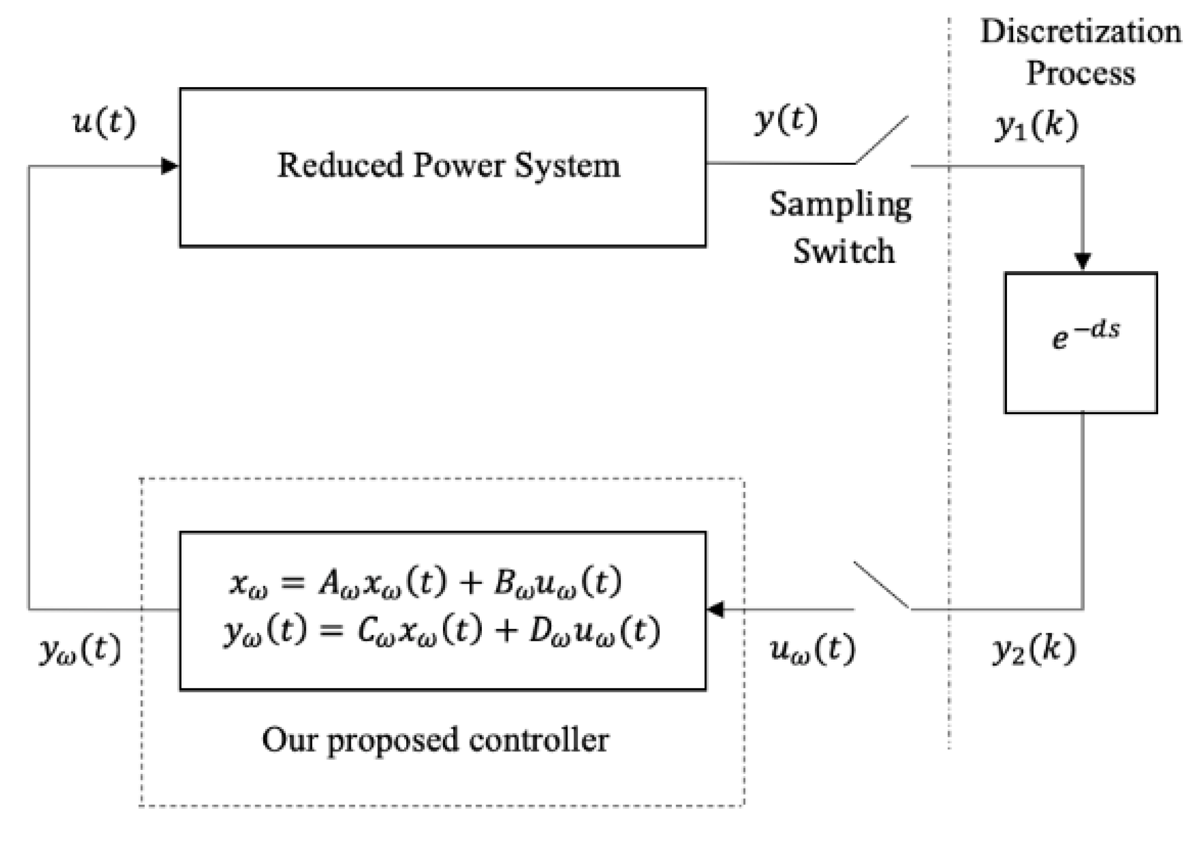
Figure 1 represents the scheme of closed-loop power system, including the power system, our proposed wide-area controller, and delay time during the transmission of wide-area signals. In addition, the packet loss of remote signals will occur during the transmission. If the power system experiences packet loss, the previous data will be used. Thus, we have:
where, is the transmission delay and is the sampling time.

Figure 1.
The structure of the augmented closed-loop power system.
The following events can describe the packet loss of wide-area signals:
There is a certain probability of packet loss, which may not happen. The probability of packet loss can be described as follows:
where, is called packet loss rate.
Furthermore, it will be yielded that:
where .
Obviously, is the discrete value of and is the continuous value of . Their relationship can be given as:
The controller in type of dynamic output feedback control is given as follows:
where, and are the input, output and state vectors of the controller. are the parameters of the proposed controller to be designed.
Hence, the augmented closed-loop power system can be represented as:
where,
Definition 1.
For constantsand, system (8) is exponentially mean-square sta ble (EMS) if the following condition holds:
Definition 2.
Define the infinitesimal generator L ofas follows:
3. Main Results
Taking an infinitesimal operator L from (9), the event can be represented by the packet loss rate in LMI (8). Thus, the sufficient conditions of the exponentially mean-square stable for the closed-loop power system (7) are discussed below.
Theorem 1.
For given positive numbermatrices, if there are positive definite matricesand any matriceswith appropriate dimensions, such that the following LMIs are satisfied, the closed-loop power system (7) is said to be exponentially mean-square stable:
where,, (, (
, ,
, ,
Proof.
Choose the following Lyapunov–Krasovskii function:
where,
The infinitesimal generator L of (9) is obtained as:
For any suitable dimensioned matrices N, M, and U, the following equations will satisfy by virtue of the Newton–Leibniz formula:
where [
Then, we will obtain:
By substituting (11) and (12) into (10), we can get the following inequality:
By applying the Schur complement theorem to (13), we can obtain:
where , .
Taking expectation on both sides of (14), it will be yielded that:
Now, let us define:
where .
Its infinitesimal operator L will be given by:
Integrating and taking expectation on both sides of (15), the following can be obtained:
where, .
Select suitable positive to make the following inequality hold.
which implies
Then, we can have
From (19), we can obtain
where .
It is observed that
Thus, (20) can be transformed into:
where .
It is concluded from (22) that system (7) is exponentially mean-square stable according to definition 1. This completes the proof. Next, we will discuss how to obtain the parameters of WADC.
Theorem 2.
For preset scalarsthe closed-loop system (7) is exponentially mean-square stable, if there are positive definite matricesany suitably dimensioned matrices,,,,,,, and revertible matrix, such that the following LMIs hold:
where,
Furthermore, the parameters of controllers are given by:
Proof.
Pre-and post-multiply (11) with and , respectively, which yields:
It is observed that:
Let be where and are given constants.
Defining.
, , , , as mentioned above and substituting (25) into (24), it can be easily known that (24) is equal to (23), which completes the proof.
Remark 1.
The system (7) is proven to be exponentially mean-square stable with mutually independentin Theorem 1. Meanwhile, in Theorem 2, for simplicity, we assume and is the packet loss rate of the remote signal.
Remark 2.
In Theorem 2, when the parametersare preset, the conditions in Theorem 2 are strict LMIs and will be solved via the LMI Toolbox in MATLAB.
Remark 3.
If the reduced-order power system is oforder, the augmented closed-loop system will be oforder. Thus,,and, the dimensions of, , , are, respectively.
4. Simulation in Four Machine Two-Area Power System
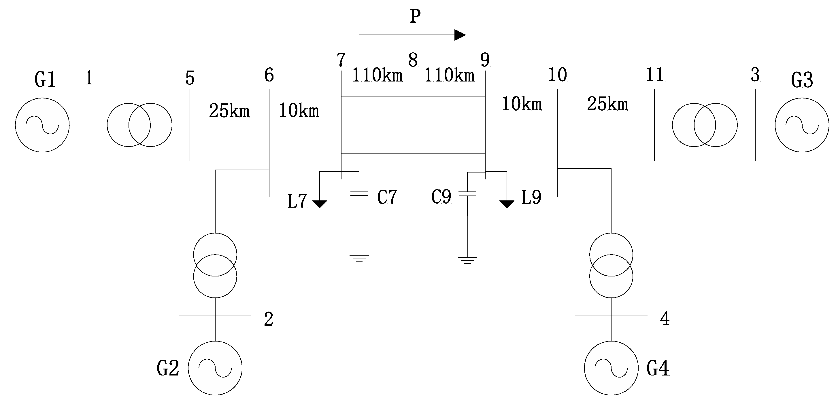
As shown in Figure 2, the test system consists of four machines in two areas, the details of which are found in [11]. Table 1 shows the results of the modal analysis. There are two local modes, which can be improved by installing local PSSs in generator 1 and 3 with detailed parameters are shown in [11]. Though the local mode is suppressed by local PSSs, the system still has an inter-area mode with a damping ratio is 0.0823 and a frequency of 0.6567 Hz. Therefore, G1 is installed by our proposed controller in the form of DOFC to restrain the inter-area mode. According to the residue approach in [18], the difference between the rotor speed of G1 and G3 is selected as the input signal of our proposed controller.
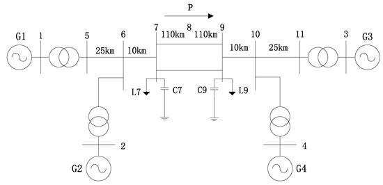
Figure 2.
Power system with four machines in two areas.

Table 1.
The results of modal analysis in a power system without a controller.
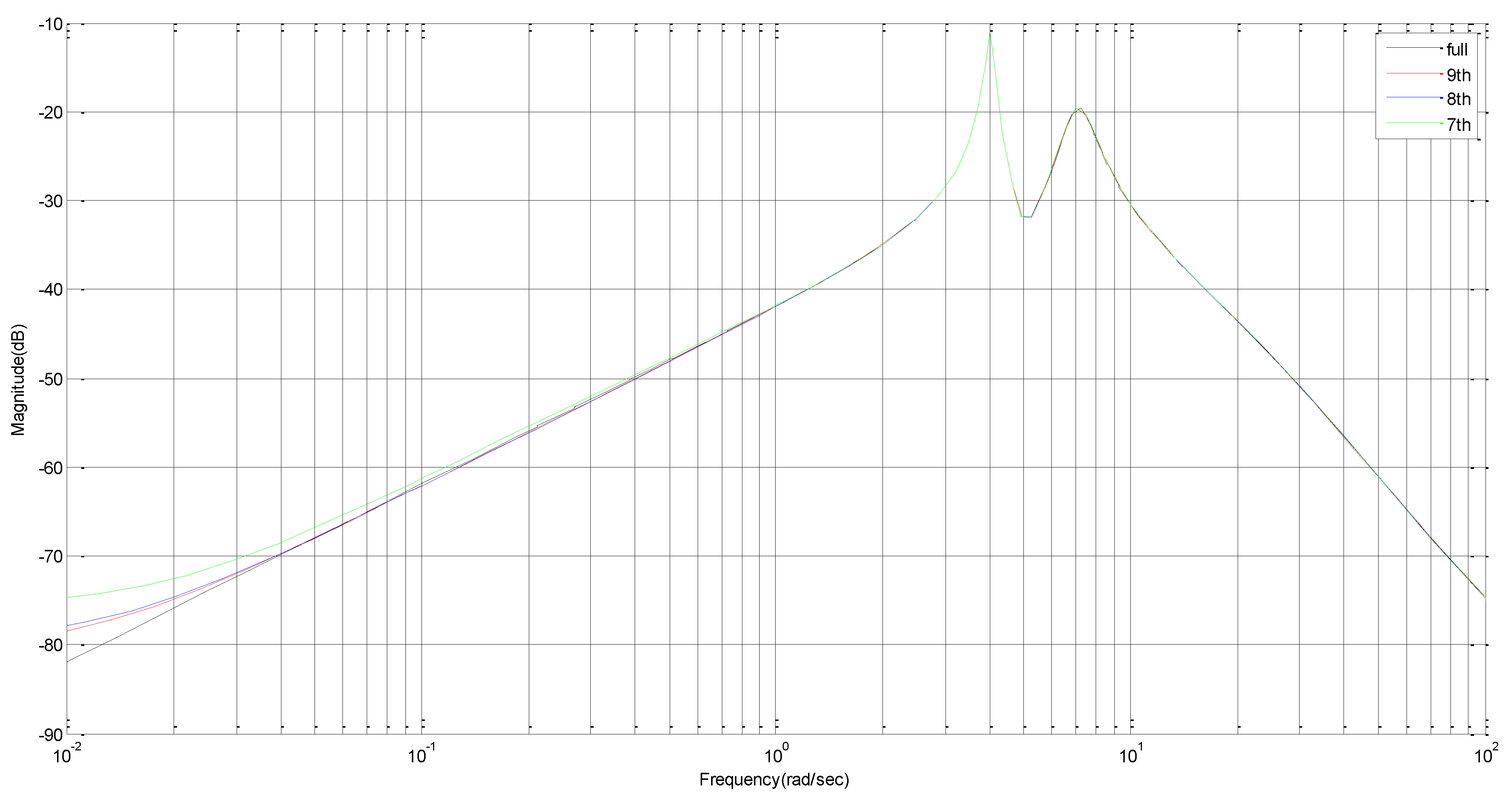
The open-loop system, where the local controller is not concluded, is of 76 orders and the reduced-order system is obtained by the Schur balanced truncation reduction technique. The frequency responses of a system with 76 orders, 9 orders and 8, orders are presented in Figure 3, and they are very close, over 0.1–2.5 Hz. Hence, the 8th order system model is used for the simulation.
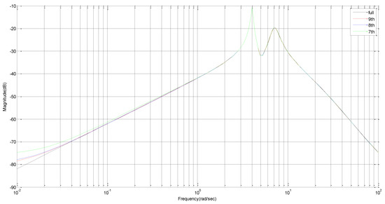
Figure 3.
The response of frequency for system with 76–order, 9–order and 8-order.
For the following given numbers, , , the parameters of the controller are obtained according to Theorem 2 by virtue of the LMI toolbox in MATLAB.
The relationship between packet loss rate and delay bound is shown in Table 2. It is clear that the increase in the packet loss rate will cause a decrease in delay bound , which means that the stability of the power system is degraded.
Table 2.
The relationship between the rate of packet loss and delay margin (ms).
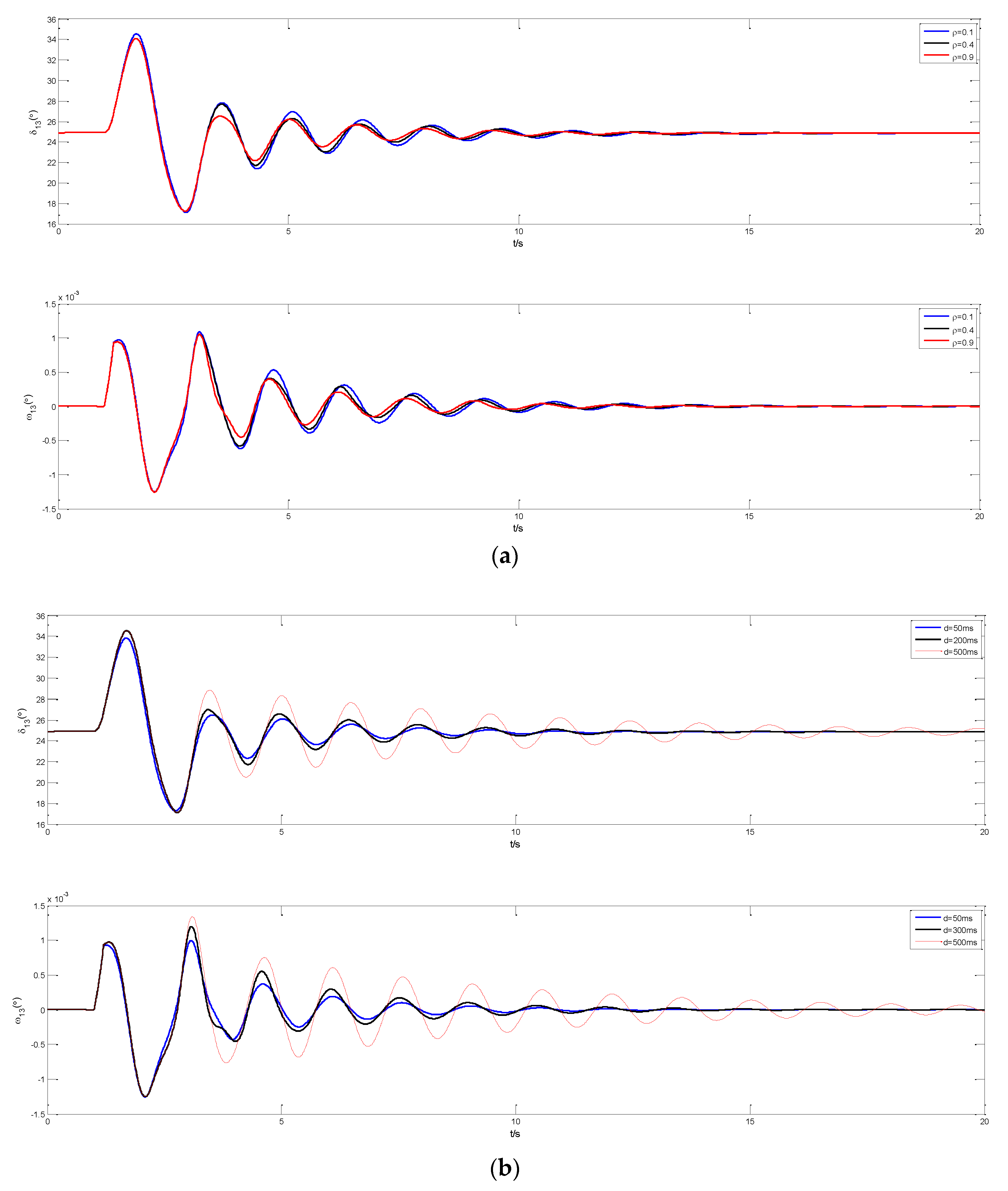
To further clarify this, the simulation is carried out under different packet loss rates where G1 is equipped with our proposed controller. The difference between angular velocity and rotor angle of G1 and G3 is selected as performance index. Three-phase short-circuit occurs at and is removed at . For the same delay , the response caves of and under different packet loss rates are shown in Figure 4a and for , the response caves of and under different delays are Figure 4b.
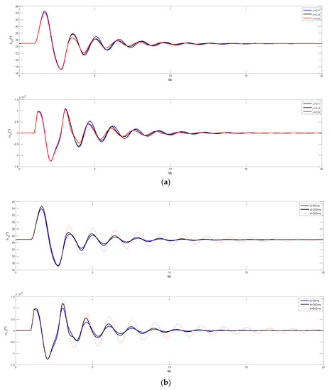
Figure 4.
(a). The trajectories under different , (b). The trajectories under different time delay with .
It can be seen from Figure 4a that the system equipped with our proposed controller has adequate damping to suppress inter-area low-frequency oscillations. Even if the packet loss rate reaches 0.9, the low-frequency oscillation can be still suppressed. Moreover, there are only slow changes in the amplitude and the regulating time of the system response as the packet loss rate increases.
From Figure 4b, we can know that the effect of damping the low-frequency oscillation will become worse as the delay increases, which also shows the importance of considering delay during the design of controller. In addition, when the delay time increases to a certain value, the system will become instable.
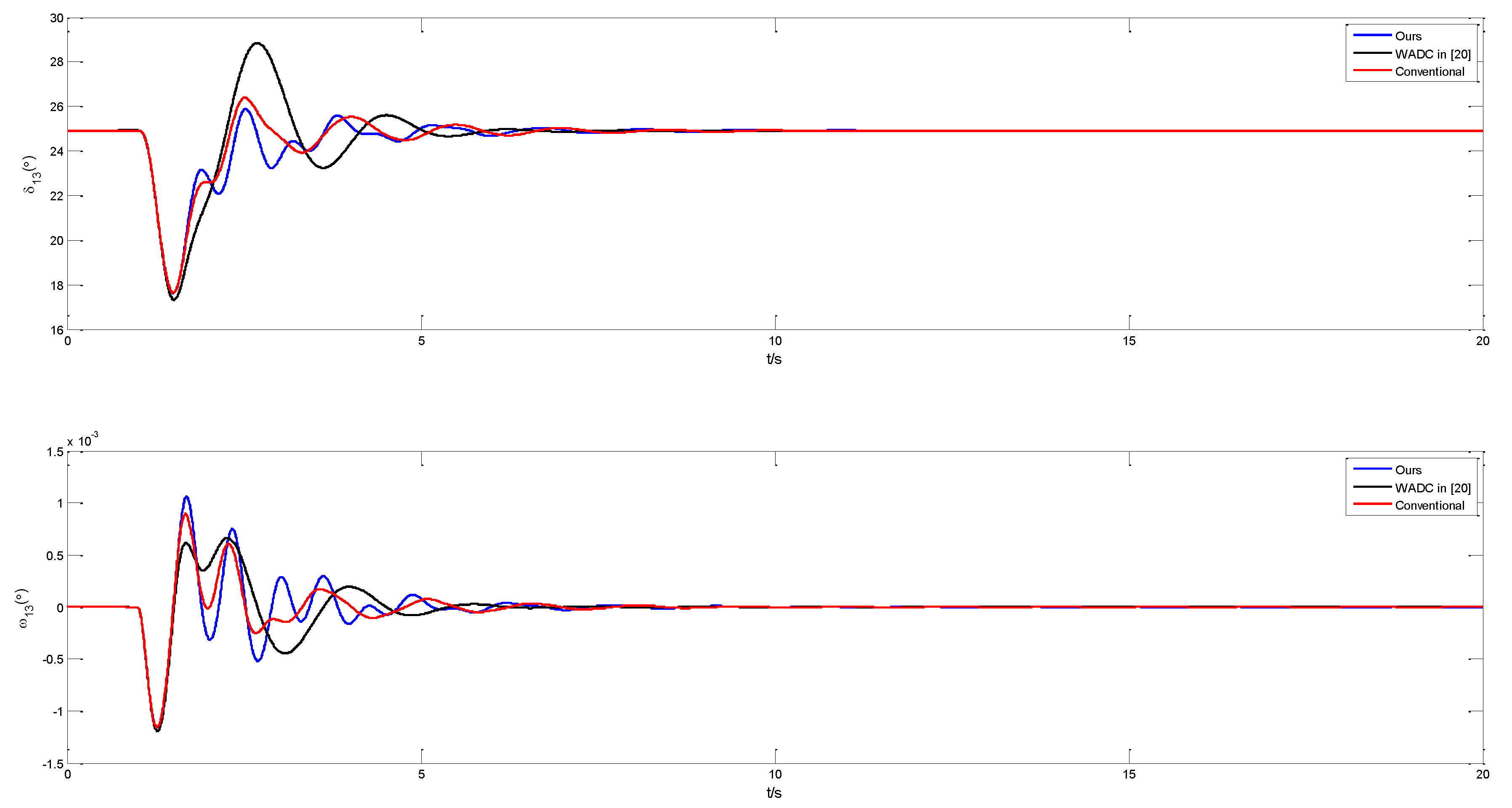
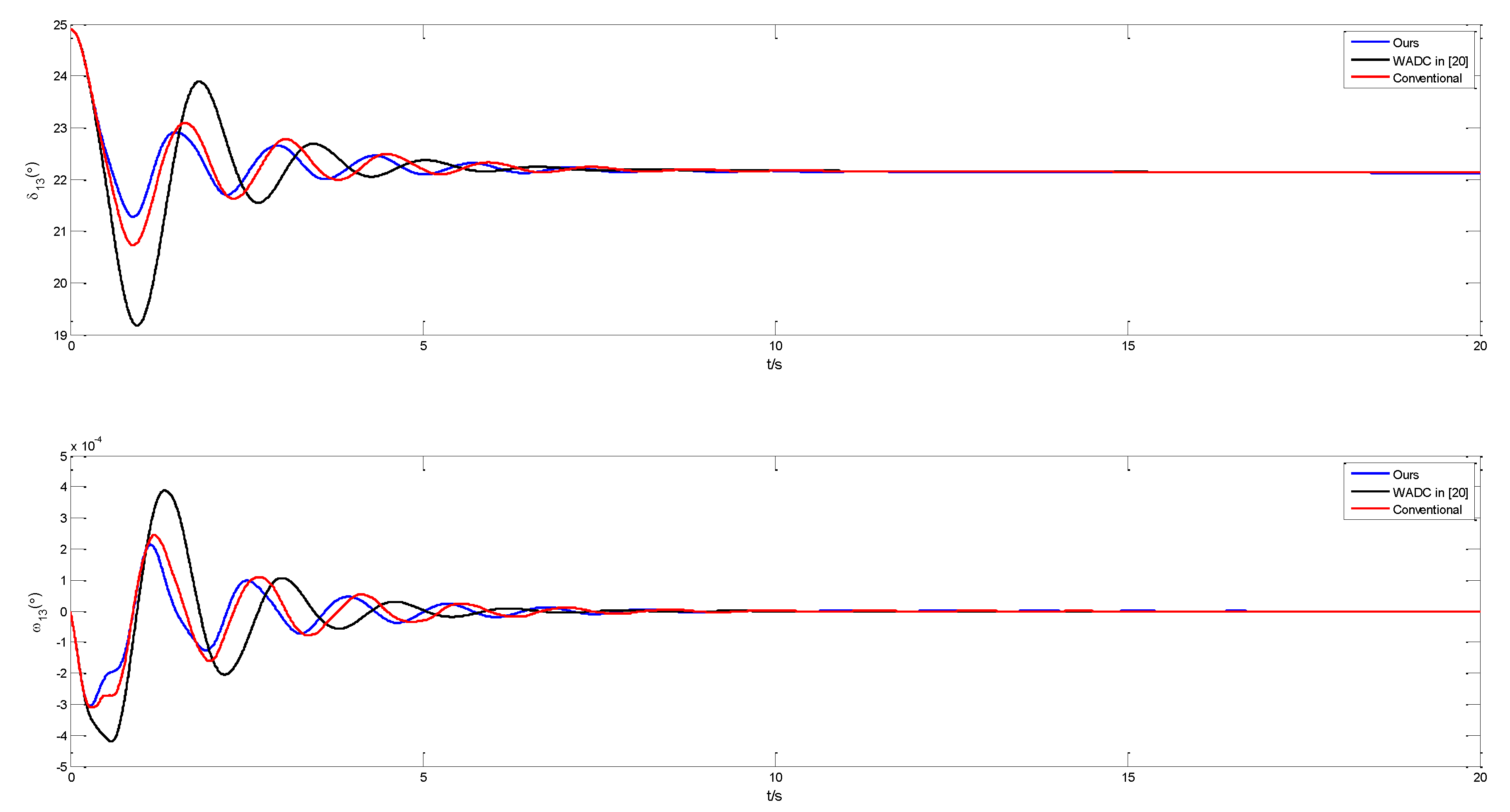
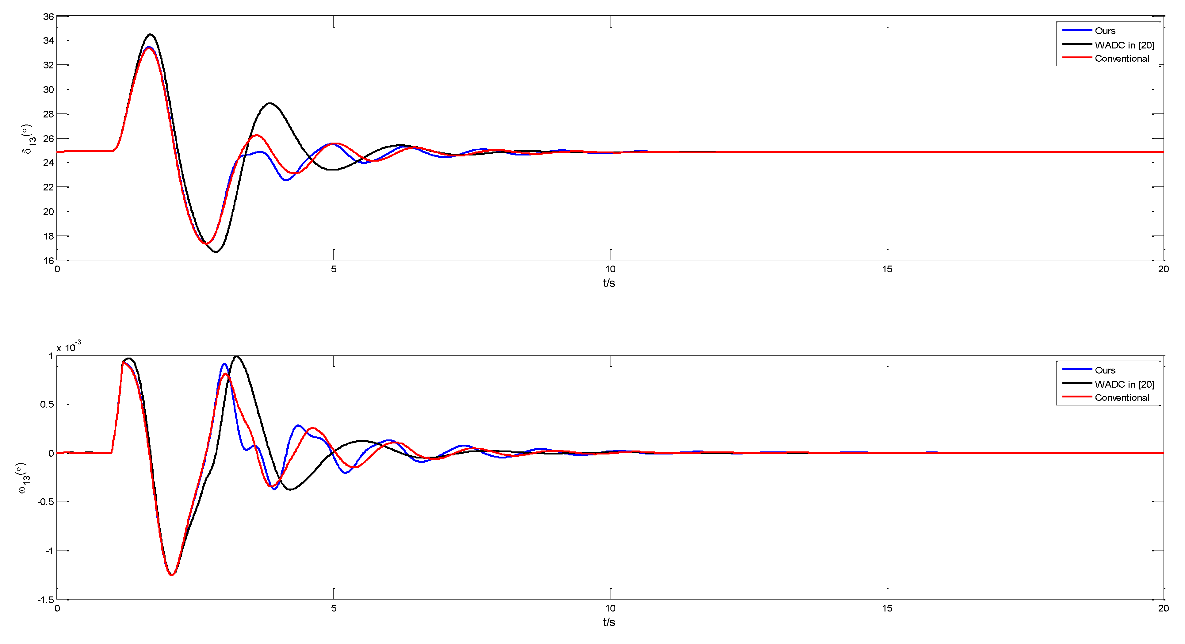
To illustrate that our controller is more effective in the case of packet loss, the comparison simulations among our controller, a conventional controller, and WADC proposed in [20] are carried out. Case studies are carried out under the following three scenarios. Scenario1: three-phase short-circuit occurs at and it is removed at . Scenario 2: , the terminal voltage of G1 increases by 5%. Scenario 3: the power flow on tie-lines increases from 413 MW to 460 MW. For delay time , the system responses under different packet loss rates are shown in the figures below.
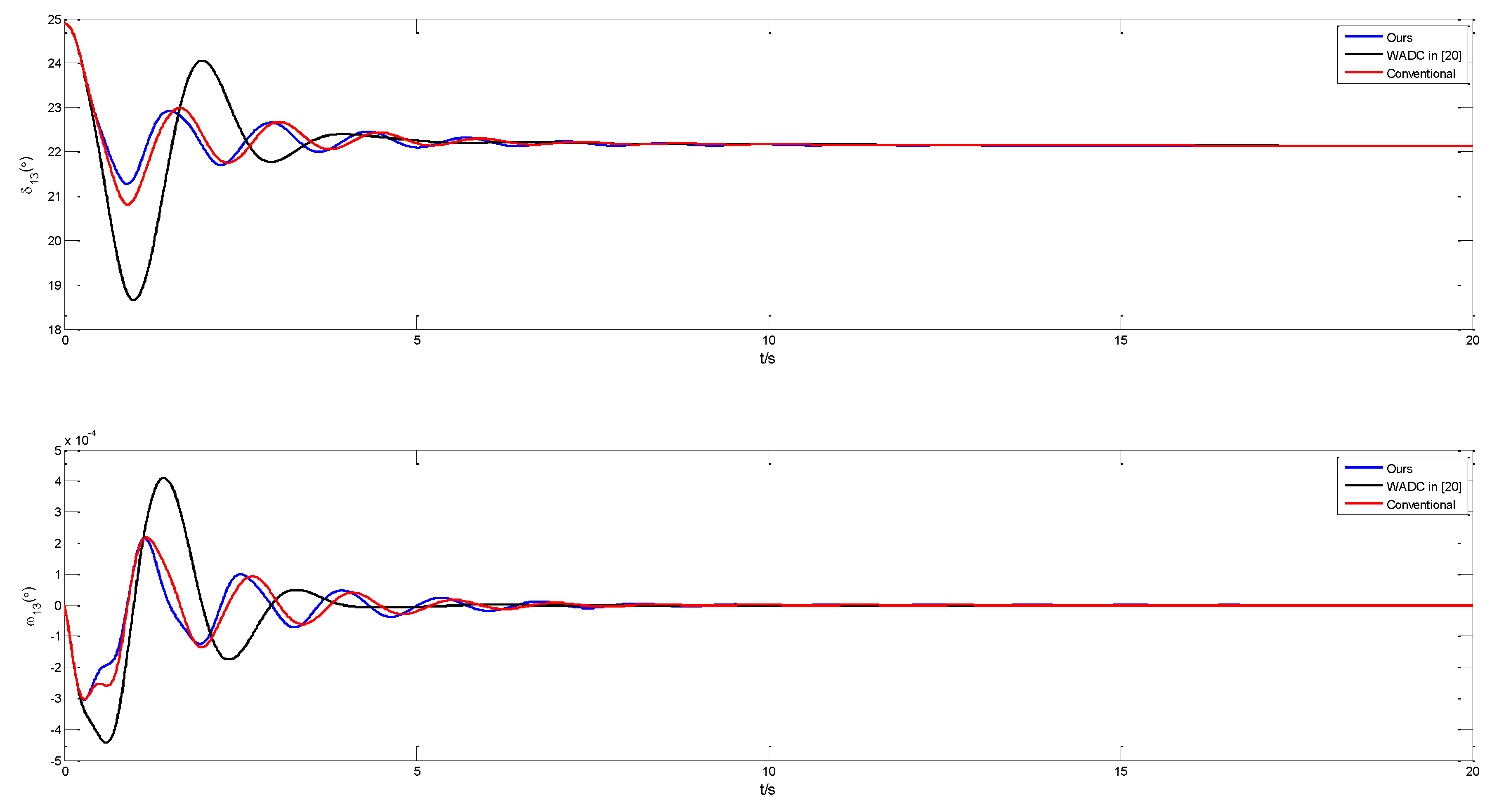
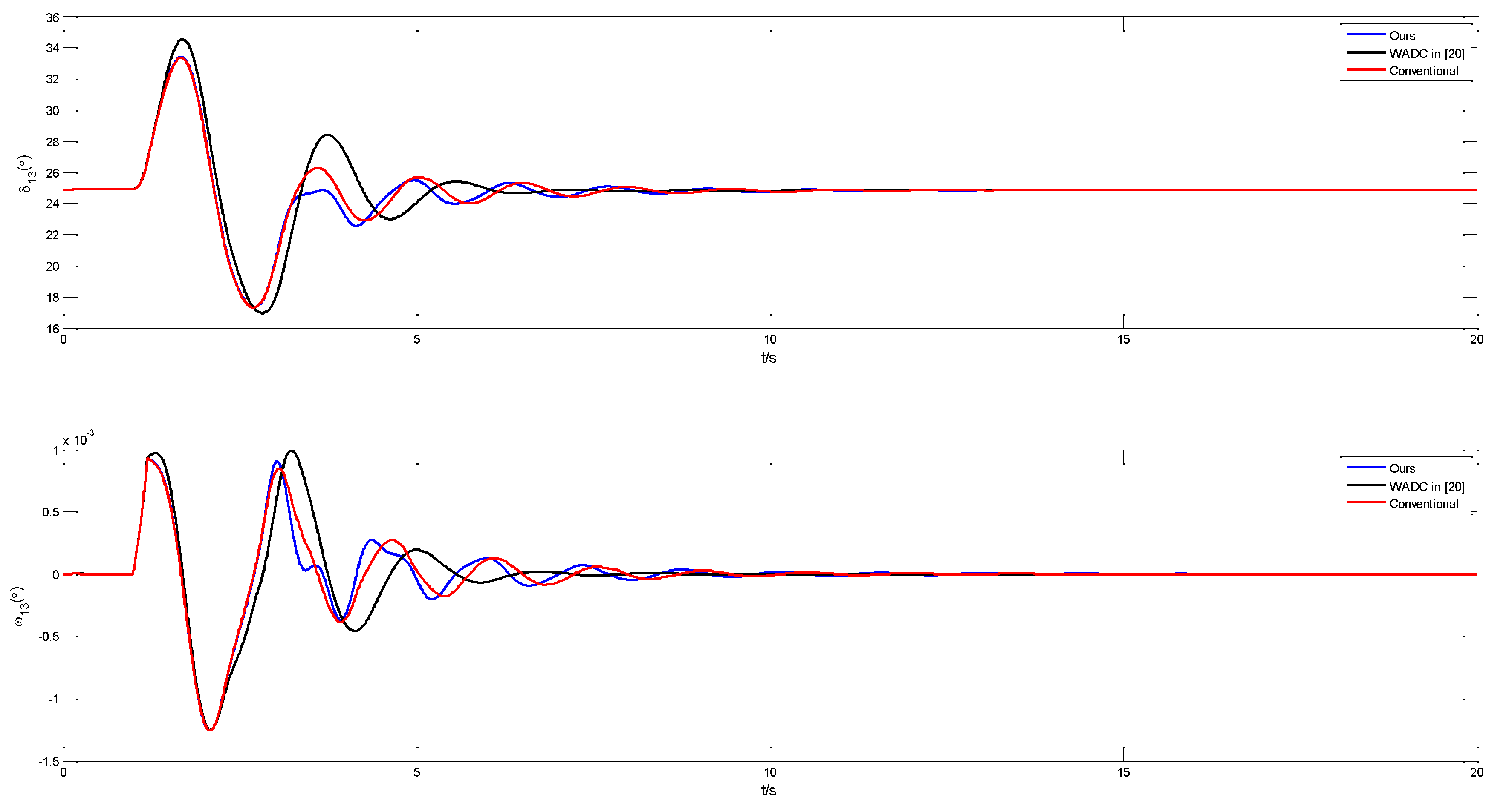
When the packet loss of wide-area signals does not occur, that is , the response curves are shown in Figure 5, Figure 6 and Figure 7, corresponding to scenarios 1, 2, 3, and some key indexes are presented in Table 3. The system with our controller, WADC in [20], and the conventional controller can all ensure the stability of the closed-loop power system under different external disturbances, but our dynamic performances are slightly better than those of WADC in [20] and the conventional controller—at least not poorer than theirs.
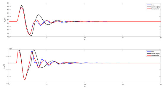
Figure 5.
Response of the system in Scenario 1 when .
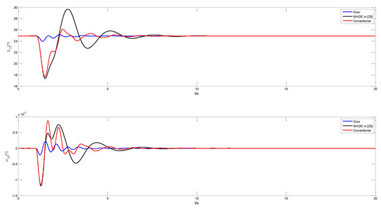
Figure 6.
Response of the system in Scenario 2 when .
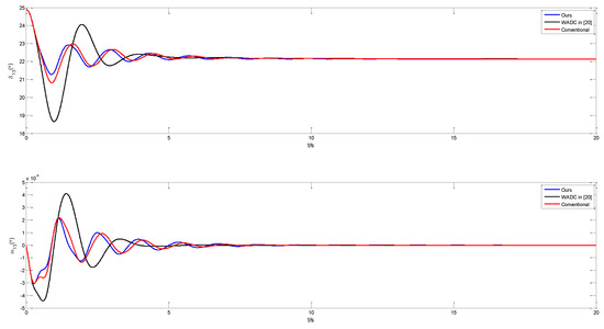
Figure 7.
Response of the system in Scenario 3 when .
Table 3.
The key index of the response curve when there is no packet loss.
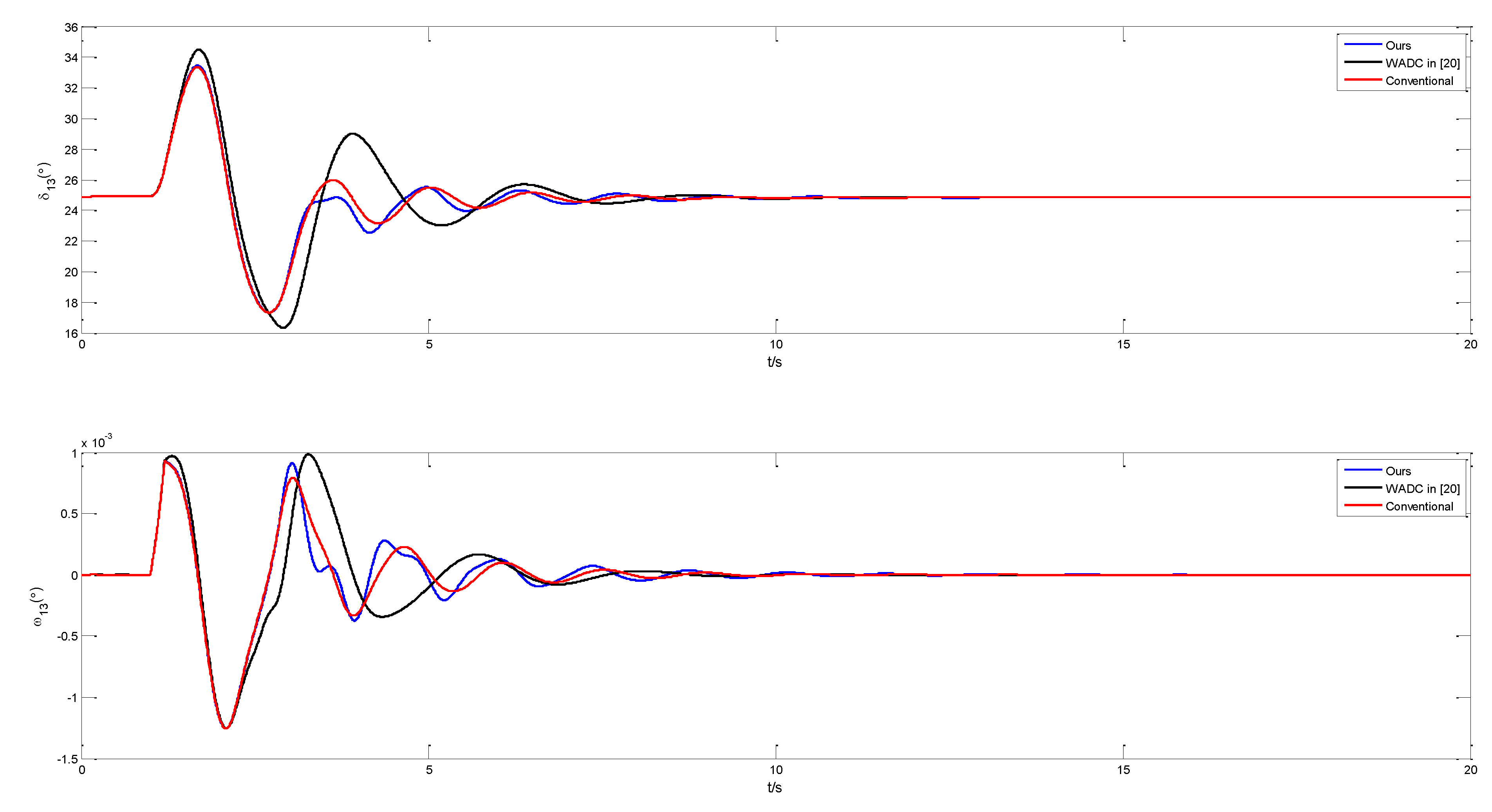
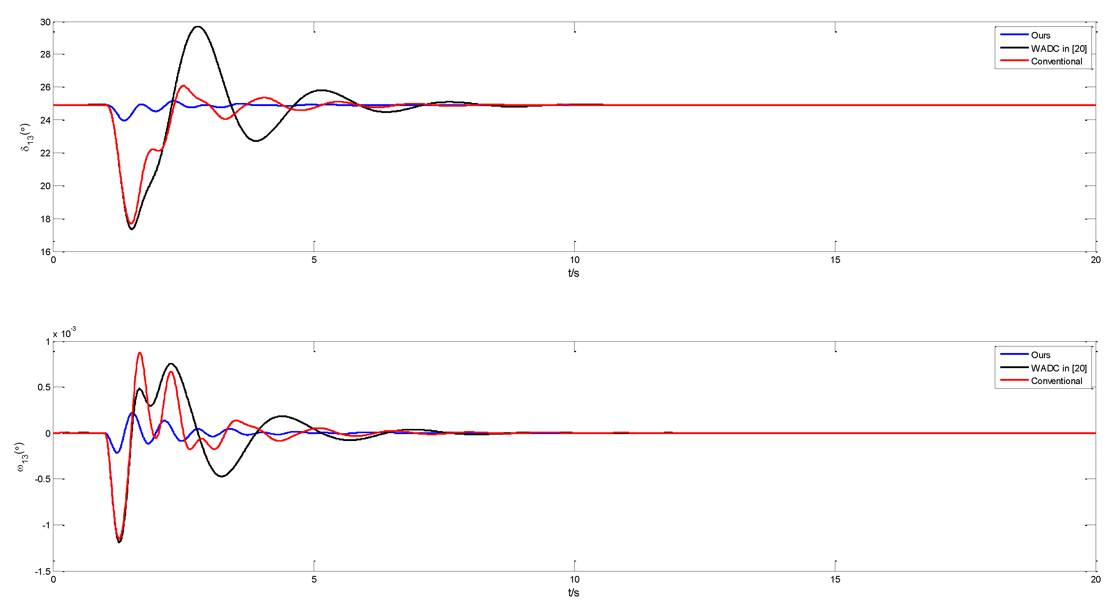
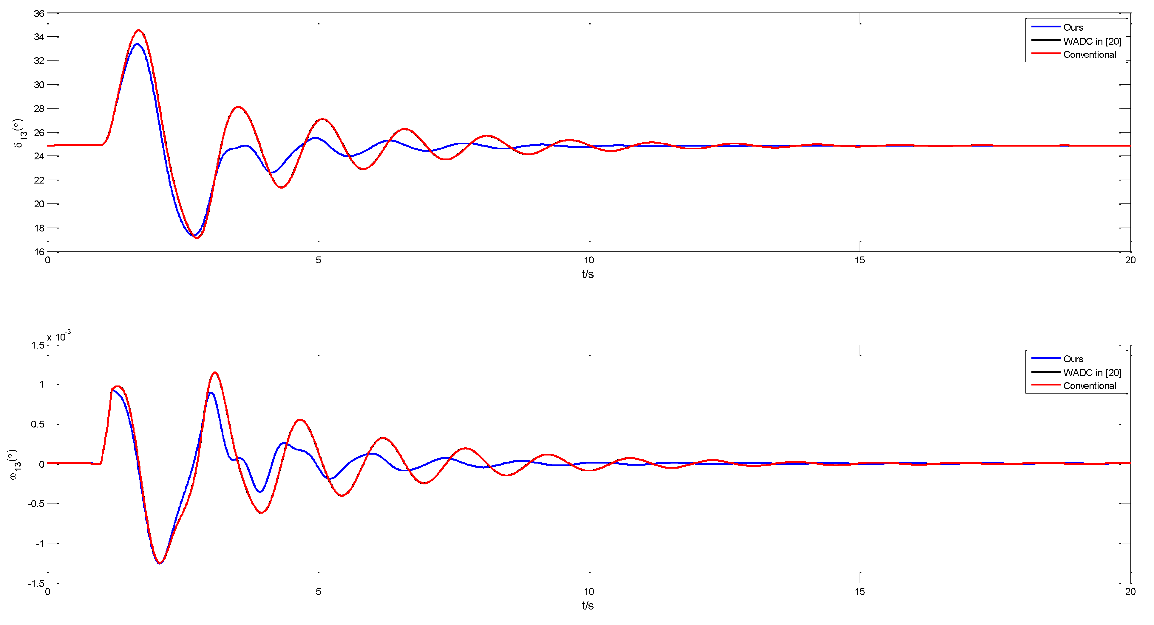
It can be easily seen from Figure 8, Figure 9, Figure 10 and Table 4 that except for the slightly larger overshoot of in Figure 9, our proposed controller can stabilize the system in a shorter time and have smaller overshoot under different external disturbances when packet loss occurs.
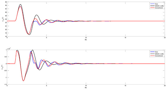
Figure 8.
Response of the system in Scenario 1 when .
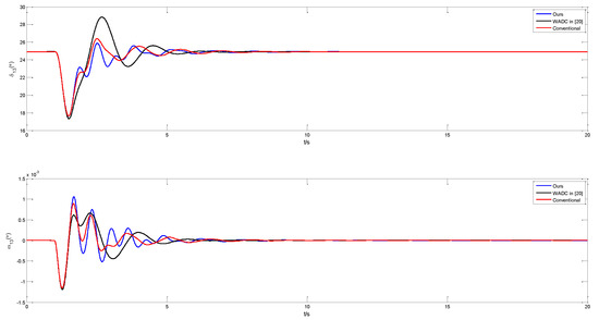
Figure 9.
Response of the system in Scenario 2 when .
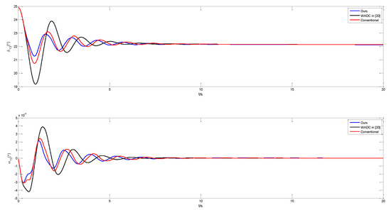
Figure 10.
Response of the system in Scenario 3 when .
Table 4.
The key index of the response curve in case of packet loss.
Next, we will present other simulation results with three controllers at different rates of packet loss.
It is obviously seen from Figure 11, Figure 12, Figure 13 that though all the controllers can stabilize the system when external disturbances occur, our proposed controller has a better dynamic performance and can stabilize the system in a shorter time. The higher the packet loss rate, the more obvious the advantage. Due to the limitation of space, we will not present other results in this paper. In all, our proposed controller, compared with WADC in [20] and conventional controller, can provide more adequate damping and have better dynamic performance.
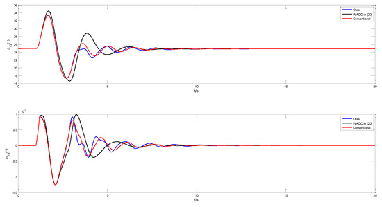
Figure 11.
Response of the system in Scenario 1 when .
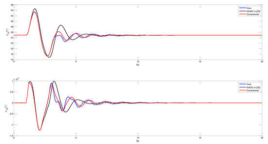
Figure 12.
Response of the system in Scenario 1 when .
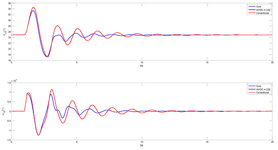
Figure 13.
Response of the system in Scenario 1 when .
5. Conclusions
The proposed wide-area DOFC can effectively damp inter-area oscillations for the power system with packet loss and time delay. The delay-dependent stability criterion exponentially mean-square stable and the techniques to obtain the delay margin and DOFC parameters with different packets loss rates are presented. The simulation results in a four-machine and two-area power system show that under different external disturbances, compared with the WADC in [18] and the conventional controller, though all the controllers can stabilize the system, our proposed controller has better performance. The higher the packet loss rate, the more obvious the advantages.
Author Contributions
Conceptualization, M.S. and Y.G. and S.S.; methodology, M.S. and Y.G.; software, M.S.; validation, M.S., Y.G. and S.S.; formal analysis, M.S. and Y.G.; investigation, Y.G.; resources, S.S.; data curation, S.S.; writing—original draft preparation, M.S. and Y.G.; writing—review and editing, M.S. and Y.G.; visualization, M.S.; supervision, supervision; project administration, M.S.; funding acquisition, M.S. and Y.G. All authors have read and agreed to the published version of the manuscript.
Funding
This research was funded by Postgraduate Innovative Project of Central South University, grant number 2020XQLH02 and The APC was funded by Postgraduate Innovative Project of Central South University.
Institutional Review Board Statement
Not applicable.
Informed Consent Statement
Not applicable.
Data Availability Statement
Data is contained within the article and supplementary material. The data presented in this study are available in Reference [20].
Conflicts of Interest
We promise that our research does not involve conflict of interest.
References
- Kundur, P. Power System Stability and Control; McGraw Hill Education Private Limited: New Delhi, India, 2010. [Google Scholar]
- Prasertwong, K.; Mithulananthan, N.; Thakur, D. Understanding low frequency oscillation in power systems. Int. J. Electr. Eng. Educ. 2010, 47, 248–262. [Google Scholar] [CrossRef]
- Surinkaew, T.; Ngamroo, I. Hierarchical Co-Ordinated Wide Area and Local Controls of DFIG Wind Turbine and PSS for Robust Power Oscillation Damping. IEEE Trans. Sustain. Energy 2016, 7, 943–955. [Google Scholar] [CrossRef]
- Zhang, J.; Chung, C.Y.; Han, Y. A Novel Modal Decomposition Control and Its Application to PSS Design for Damping Interarea Oscillations in Power Systems. IEEE Trans. Power Syst. A Publ. Power Eng. Soc. 2012, 27, 2015–2025. [Google Scholar] [CrossRef]
- Ray, S.; Venayagamoorthy, G.K. Wide area signal based optimal neuro-controller for a UPFC. IEEE Trans. Power Deliv. 2008, 23, 1597–1605. [Google Scholar] [CrossRef]
- Kim, D.-I.; White, A.; Shin, Y.-J. PMU-Based Event Localization Technique for Wide-Area Power System. IEEE Trans. Power Syst. 2018, 33, 5875–5883. [Google Scholar] [CrossRef]
- Fesharaki, F.H.; Hooshmand, R.A.; Khodabakhshian, A. Simultaneous Optimal Design of Measurement and Communication Infrastructures in Hierar-chical Structured WAMS. IEEE Trans. Smart Grid 2014, 5, 312–319. [Google Scholar] [CrossRef]
- Agnihotri, P.; Kulkarni, A.M.; Gole, A.M.; Archer, B.A.; Weekes, T. A Robust Wide-Area Measurement-Based Damping Controller for Networks with Embedded Multiterminal and Multiinfeed HVDC Links. IEEE Trans. Power Syst. 2017, 32, 3884–3892. [Google Scholar] [CrossRef]
- Jiang, L.; Yao, W.; Wu, Q.H.; Wen, J.Y.; Cheng, S.J. Delay-Dependent Stability for Load Frequency Control With Constant and Time-Varying Delays. IEEE Trans. Power Syst. 2011, 27, 932–941. [Google Scholar] [CrossRef]
- Kamwa, I.; Samantaray, S.R.; Joos, G. Compliance Analysis of PMU Algorithms and Devices for Wide-Area Stabilizing Control of Large Power Systems. IEEE Trans. Power Syst. 2012, 28, 1766–1778. [Google Scholar] [CrossRef]
- Yao, W.; Jiang, L.; Wu, Q.H.; Wen, J.Y.; Cheng, S.J. Delay-Dependent Stability Analysis of the Power System With a Wide-Area Damping Controller Embedded. IEEE Trans. Power Syst. 2010, 26, 233–240. [Google Scholar] [CrossRef]
- Yao, W.; Jiang, L.; Wen, J.; Wu, Q.H.; Cheng, S. Wide-Area Damping Controller of FACTS Devices for Inter-Area Oscillations Considering Communication Time Delays. IEEE Trans. Power Syst. 2013, 29, 318–329. [Google Scholar] [CrossRef] [Green Version]
- Prakash, T.; Singh, V.P.; Mohanty, S.R. A synchrophasor measurement based wide-area power system stabilizer design for inter-area oscillation damping considering variable time-delays. Int. J. Electr. Power Energy Syst. 2019, 105, 131–141. [Google Scholar] [CrossRef]
- Zhu, K.; Rahimi, S.; Nordström, L.; Zhang, B. Design phasor data concentrator as adaptive delay buffer for wide-area damping control. Electr. Power Syst. Res. 2015, 127, 22–31. [Google Scholar] [CrossRef]
- Niu, X.; Ye, H.; Liu, Y.; Liu, X. Padé approximation based method for computation of eigenvalues for time delay power system. In Proceedings of the 48th International Universities' Power Engineering Conference (UPEC), Dublin, Ireland, 2–5 September 2013; pp. 1–4. [Google Scholar] [CrossRef]
- Majumder, R.; Chaudhuri, B.; Pal, B.; Zhong, Q.-C. A unified Smith predictor approach for power system damping control design using remote signals. IEEE Trans. Control. Syst. Technol. 2005, 13, 1063–1068. [Google Scholar] [CrossRef] [Green Version]
- Yu, S.S.; Chau, T.K.; Fernando, T.L.; Iu, H.H.-C. An Enhanced Adaptive Phasor Power Oscillation Damping Approach with Latency Compensation for Modern Power Systems. IEEE Trans. Power Syst. 2017, 33, 4285–4296. [Google Scholar] [CrossRef]
- Meng, L.; Yong, C.; Chen, A. Wide-Area Dynamic Damping Controller Based on Robust H∞ Control for Wide-Area Power Systems With Random Delay and Packet Dropout. IEEE Trans. Power Syst. 2018, 33, 4026–4037. [Google Scholar]
- Zhang, C.K.; Jiang, L.; Wu, Q.H.; He, Y.; Wu, M. Delay-Dependent Robust Load Frequency Control for Time Delay Power Systems. IEEE Trans. Power Syst. 2013, 28, 2192–2201. [Google Scholar] [CrossRef]
- Sun, M.; Nian, X.; Dai, L.; Guo, H. The design of delay-dependent wide-area DOFC with prescribed degree of stability alpha for damping inter-area low-frequency oscillations in power system. ISA Trans. 2017, 68, 82. [Google Scholar] [CrossRef]
- Alghamdi, S.; Markovic, U.; Stanojev, O.; Schiffer, J.; Hug, G.; Aristidou, P. Wide-area oscillation damping in low-inertia grids under time-varying communication delays. Electr. Power Syst. Res. 2020, 189, 106629. [Google Scholar] [CrossRef]
- Darabian, M.; Bagheri, A. Design of adaptive wide-area damping controller based on delay scheduling for improving small-signal oscilla-tions. Int. J. Electr. Power Energy Syst. 2021, 133, 107224. [Google Scholar] [CrossRef]
- Molina-Cabrera, A.; Ríos, M.A.; Besanger, Y.; Hadjsaid, N. A latencies tolerant model predictive control approach to damp Inter-area oscillations in delayed power systems. Int. J. Electr. Power Energy Syst. 2018, 98, 199–208. [Google Scholar] [CrossRef]
- Padhy, B.P.; Srivastava, S.C.; Verma, N.K. A Wide-Area Damping Controller Considering Network Input and Output Delays and Packet Drop. IEEE Trans. Power Syst. 2016, 32, 166–176. [Google Scholar] [CrossRef]
- Mekki, K.; Snyder, A.F.; HadjSaid, N.; Feuillet, R.; Georges, D.; Margotin, T. Damping controller input-signal loss effects on the wide-area stability of an interconnected power system. In Proceedings of the 2000 Power Engineering Society Summer Meeting (Cat. No.00CH37134), Seattle, WA, USA, 16–20 July 2000; pp. 1015–1019. [Google Scholar]
- Sevilla, F.R.S.; Jaimoukha, I.M.; Chaudhuri, B.; Korba, P. A Semidefinite Relaxation Procedure for Fault-Tolerant Observer Design. IEEE Trans. Autom. Control. 2015, 60, 3332–3337. [Google Scholar] [CrossRef] [Green Version]
- Segundo Sevilla, F.R.; Jaimoukha, I.; Chaudhuri, B.; Korba, P. Fault-tolerant control design to enhance damping of inter-area oscillations in power grids. Int. J. Robust Nonlinear Control. 2014, 24, 1304–1316. [Google Scholar] [CrossRef] [Green Version]
- Wang, S.; Meng, X.; Chen, T. Wide-Area Control of Power Systems through Delayed Network Communication. IEEE Trans. Control. Syst. Technol. 2011, 20, 495–503. [Google Scholar] [CrossRef]
- Li, Y.; Zhou, Y.; Liu, F.; Cao, Y.; Rehtanz, C. Design and Implementation of Delay-Dependent Wide-Area Damping Control for Stability Enhancement of Power Systems. IEEE Trans. Smart Grid 2016, 8, 1831–1842. [Google Scholar] [CrossRef]
- Li, Y.; Liu, F.; Rehtanz, C.; Luo, L.; Cao, Y. Dynamic output-feedback wide area damping control of HVDC transmission considering signal time-varying delay for stability enhancement of interconnected power systems. Renew. Sustain. Energy Rev. 2012, 16, 5747–5759. [Google Scholar] [CrossRef]
- Zhang, Y.; Dong, Y.; Hu, S. WAMS-based dynamic output-feedback control of power systems with network-induced delay and random data missing. In Proceedings of the 2015 34th Chinese Control Conference (CCC), Hangzhou, China, 28–30 July 2015. [Google Scholar]
- Chaudhuri, B.; Majumder, R.; Pal, B. Wide-Area Measurement-Based Stabilizing Control of Power System Considering Signal Transmission Delay. IEEE Trans. Power Syst. 2004, 19, 1971–1979. [Google Scholar] [CrossRef] [Green Version]

Publisher’s Note: MDPI stays neutral with regard to jurisdictional claims in published maps and institutional affiliations. |
© 2021 by the authors. Licensee MDPI, Basel, Switzerland. This article is an open access article distributed under the terms and conditions of the Creative Commons Attribution (CC BY) license (https://creativecommons.org/licenses/by/4.0/).