
Performance Comparison of Advanced Transcritical Power Cycles with High-Temperature Working Fluids for the Engine Waste Heat Recovery


Abstract
:1. Introduction
1.1. Background
1.2. Organic Rankine Cycles
1.3. Cycle Configurations
1.4. Working Fluids
1.5. Work’s Aim
- Analyze and compare the performances of split cycle and dual pressure cycle for different high-temperature working fluids.
- Investigate the effects of turbine inlet temperature and pressure, split ratio, evaporation temperature on the system performances for the split cycle and dual pressure cycle. Conduct the sensitivity analysis of turbomachinery efficiency and obtain the system performance under different condensation modes.
- Optimize the system parameters of the considered two cycles to obtain the corresponding maximum net works, and conduct the performance comparison.
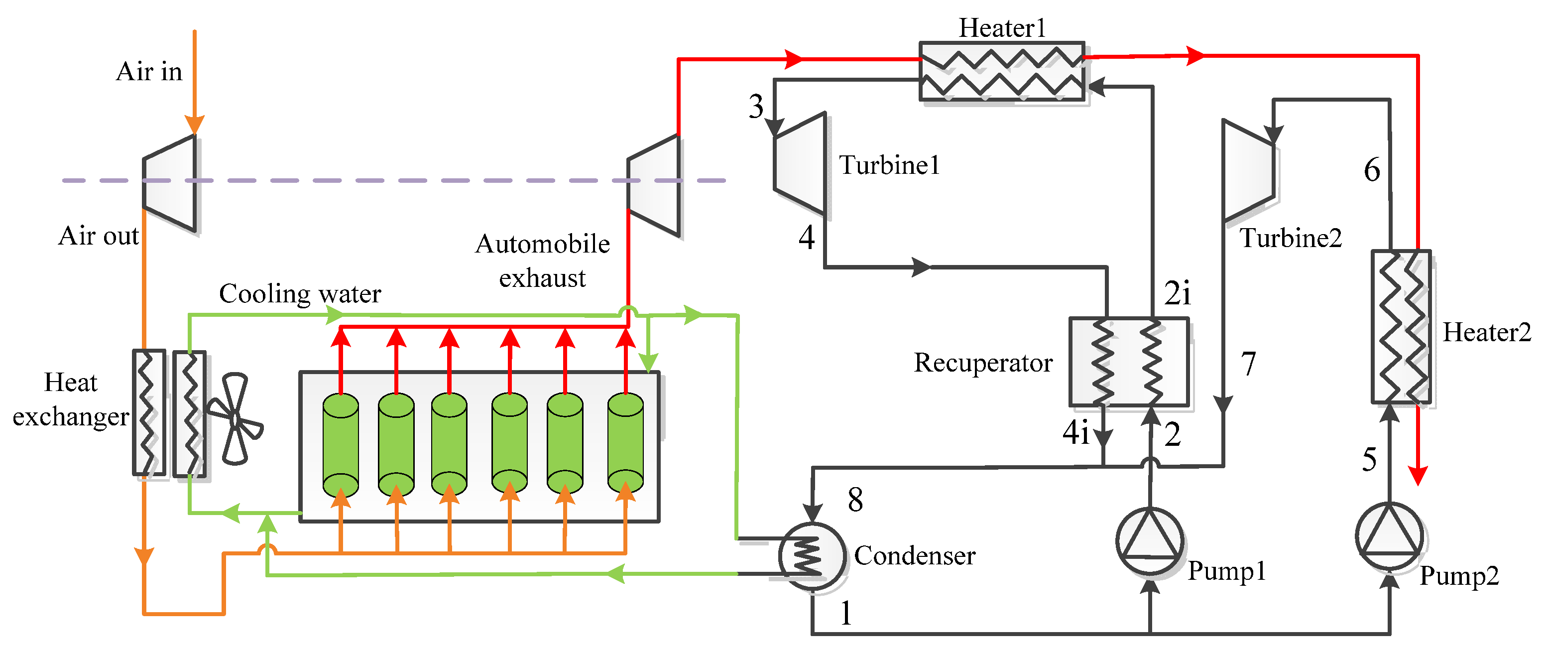
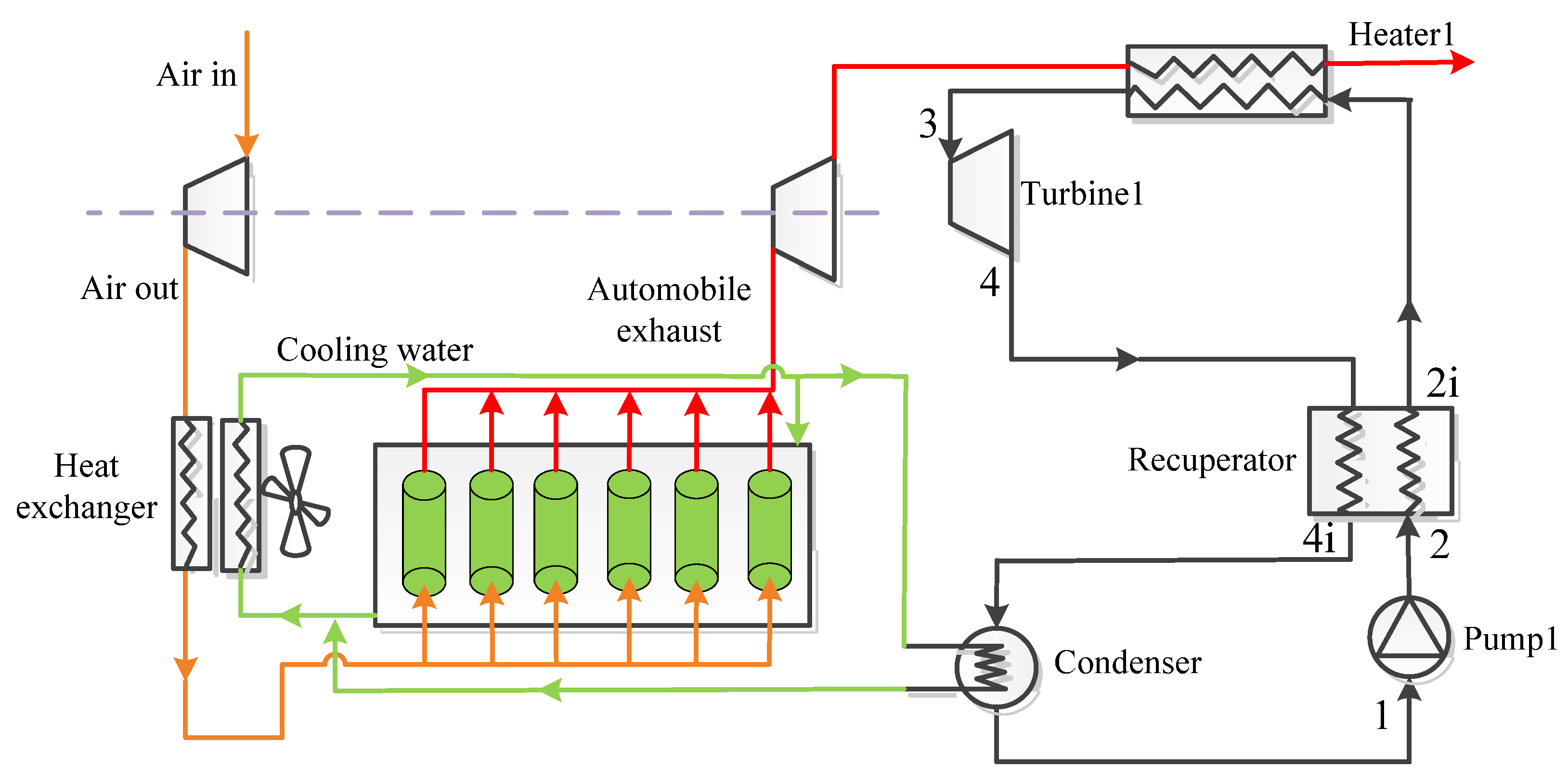
2. Cycle Layouts
3. Thermodynamic Modeling and Optimization
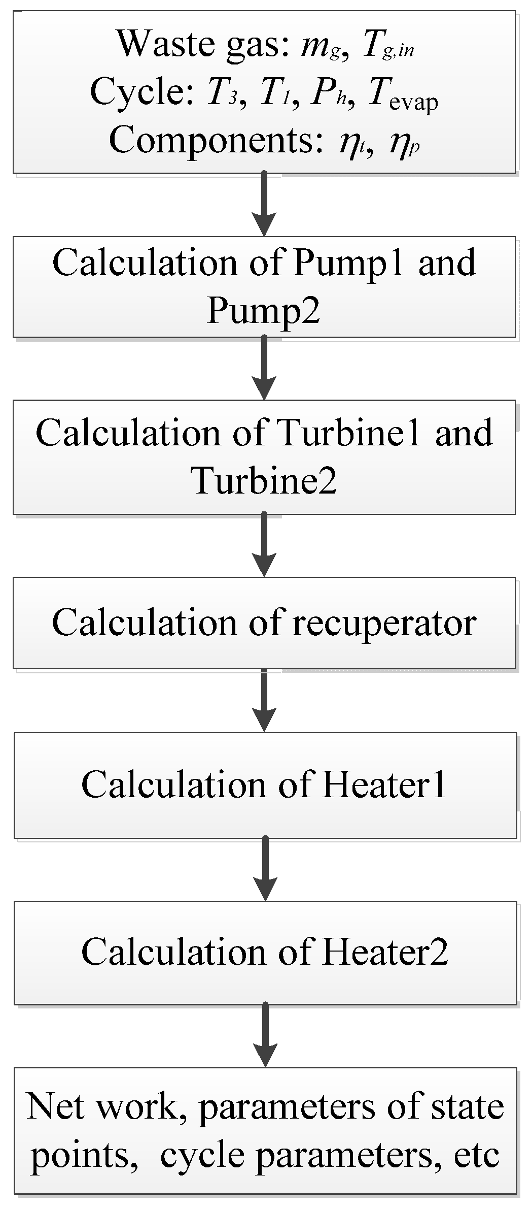
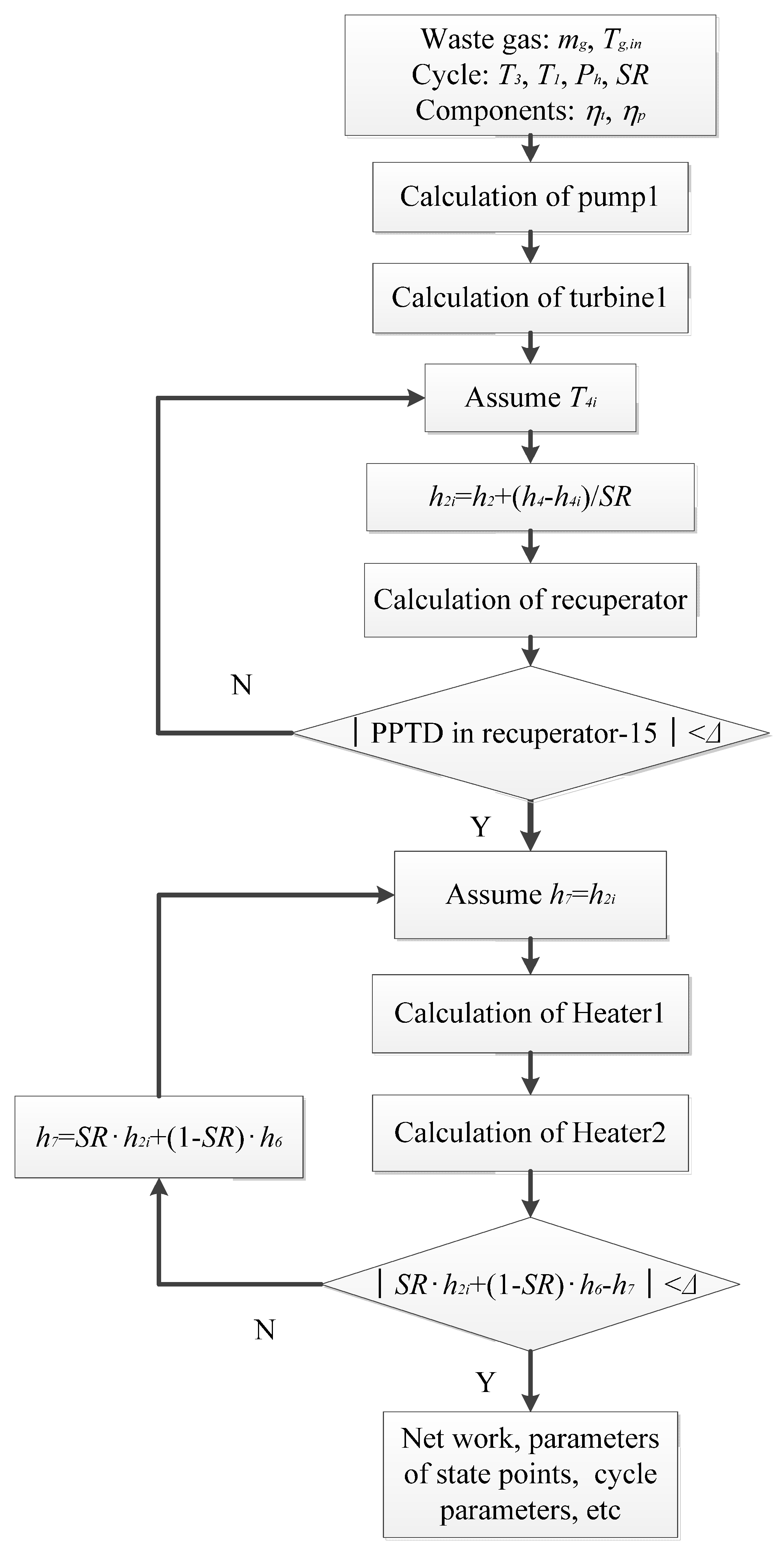
3.1. Thermodynamic Modeling
- The system operates in a steady-state, and working fluid has no change in kinetic energy and potential energy.
- No heat losses from system components and pipelines.
- No pressure drops in the heater, condenser or pipelines.
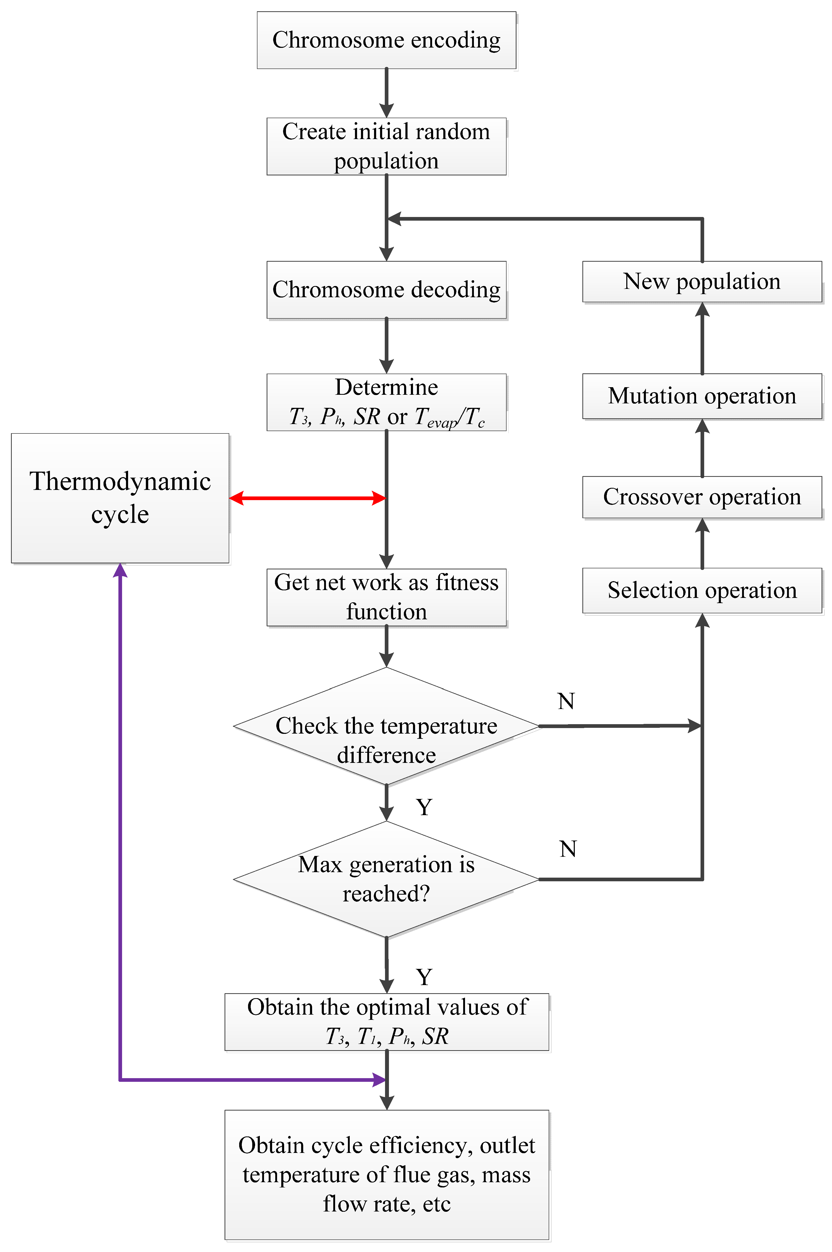
3.2. GA Optimization
4. Cycle Conditions and Potential Working Fluids
5. Results and Discussion
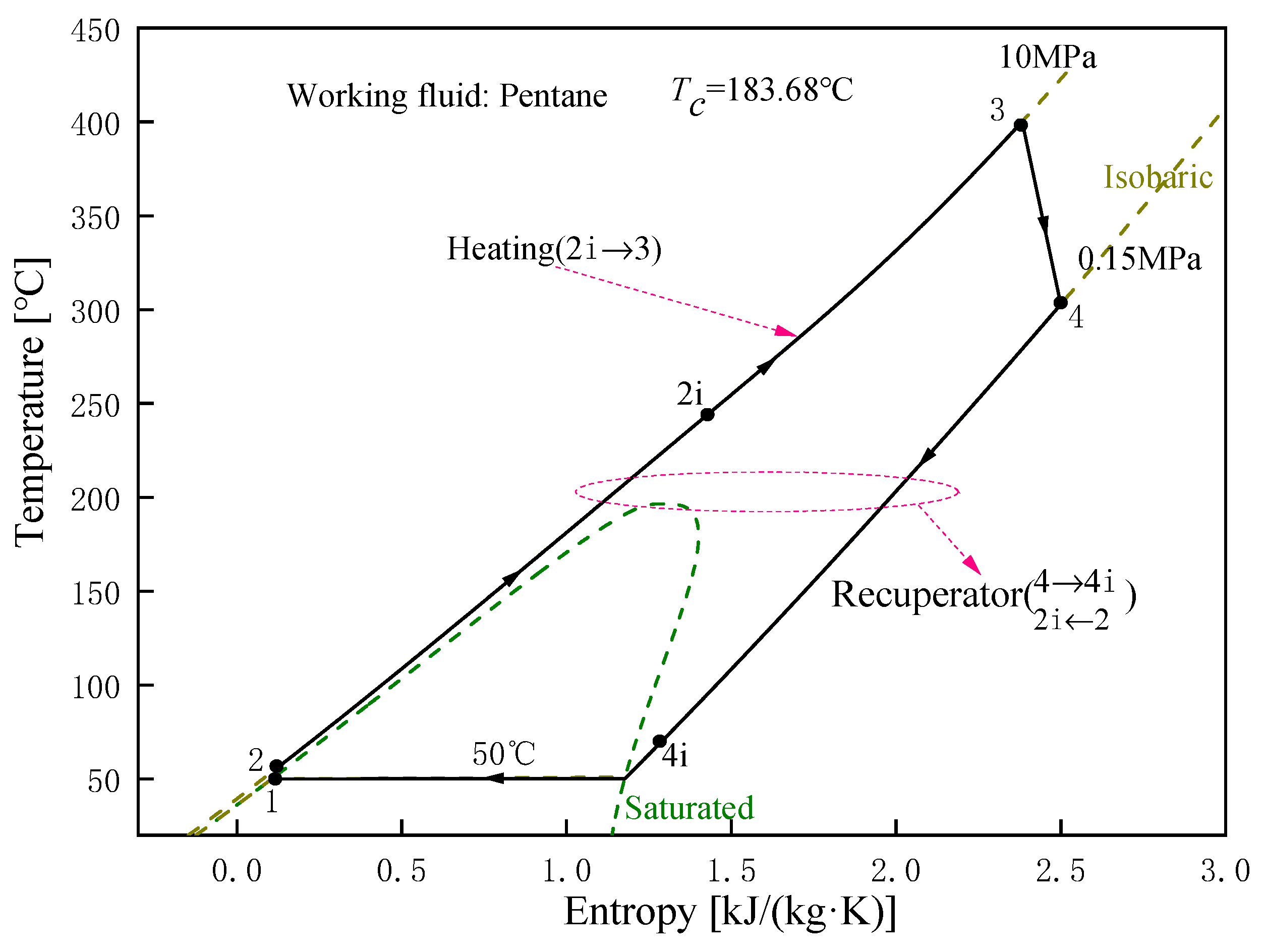
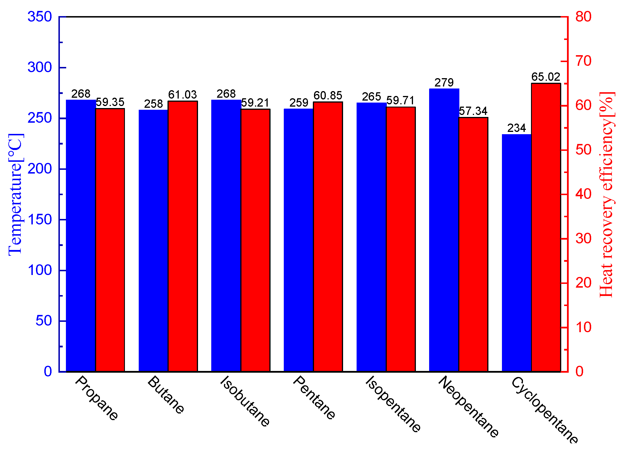
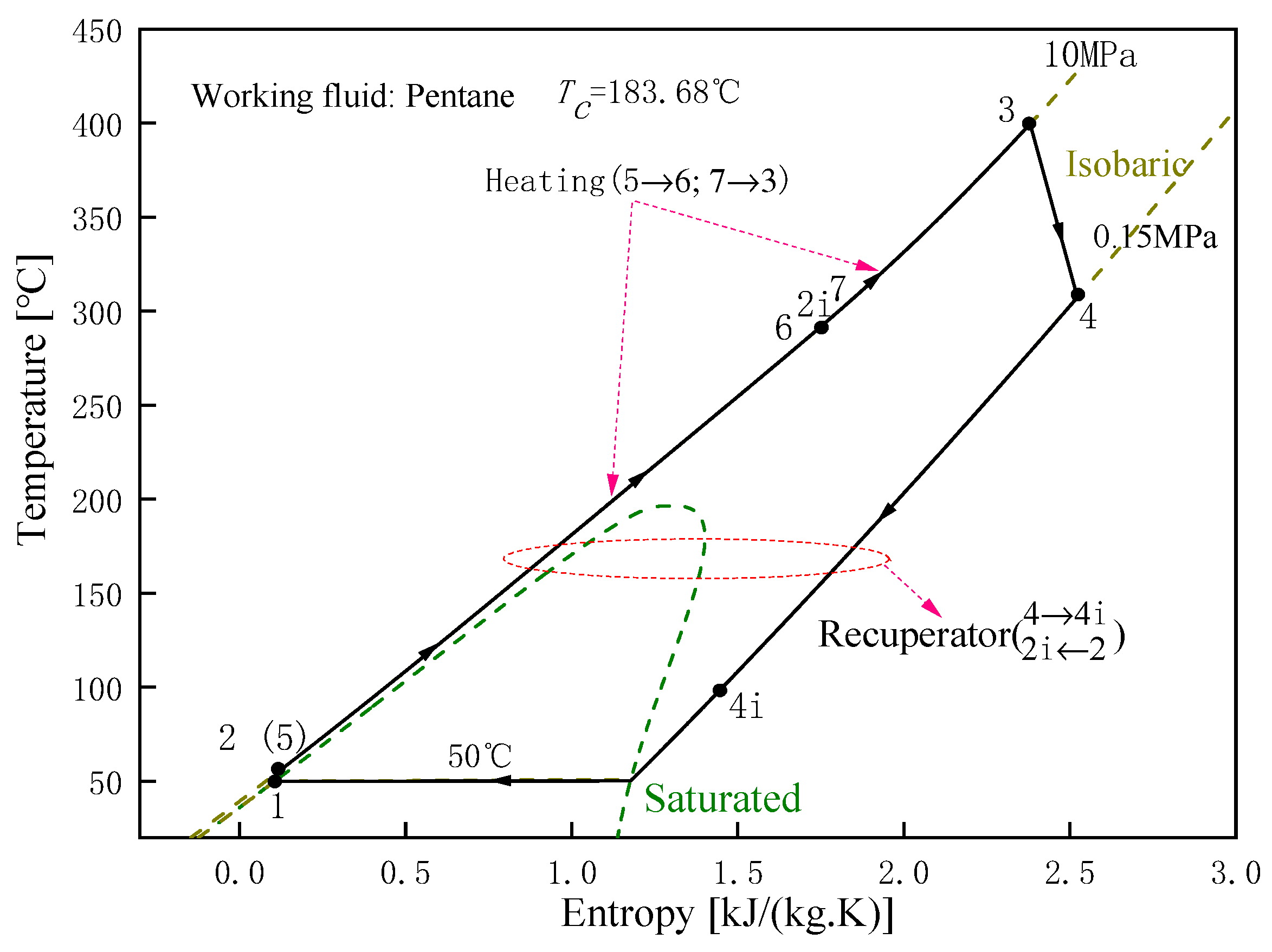
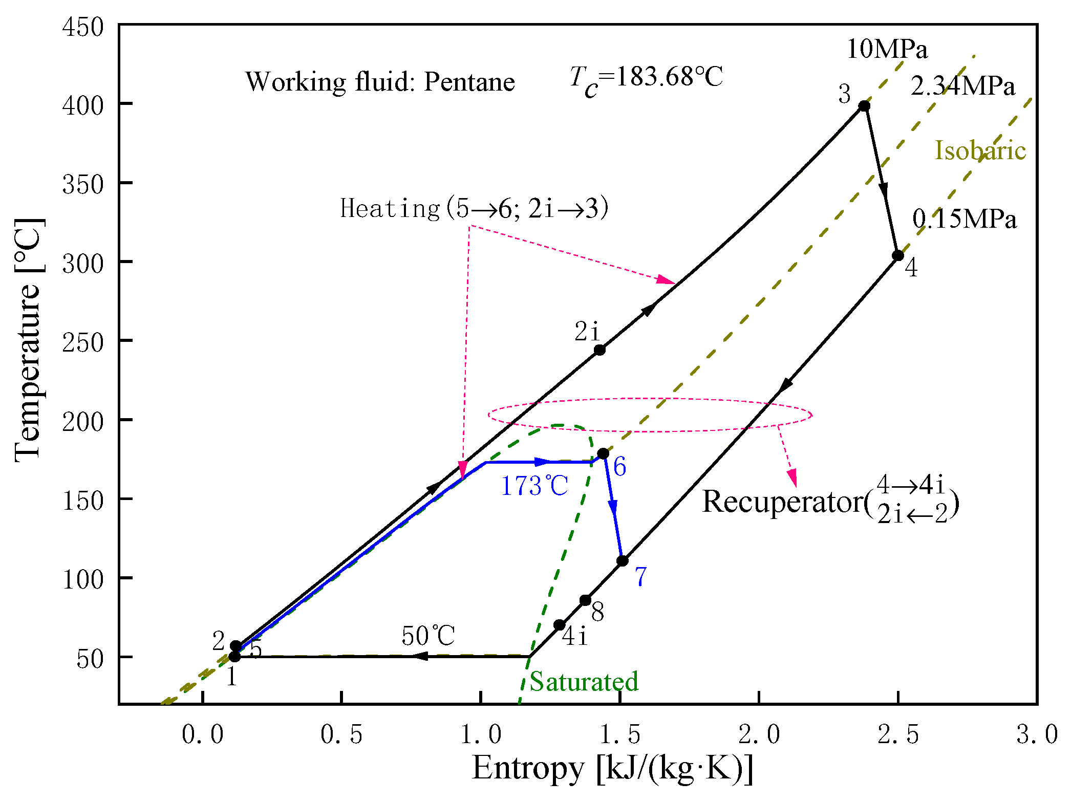
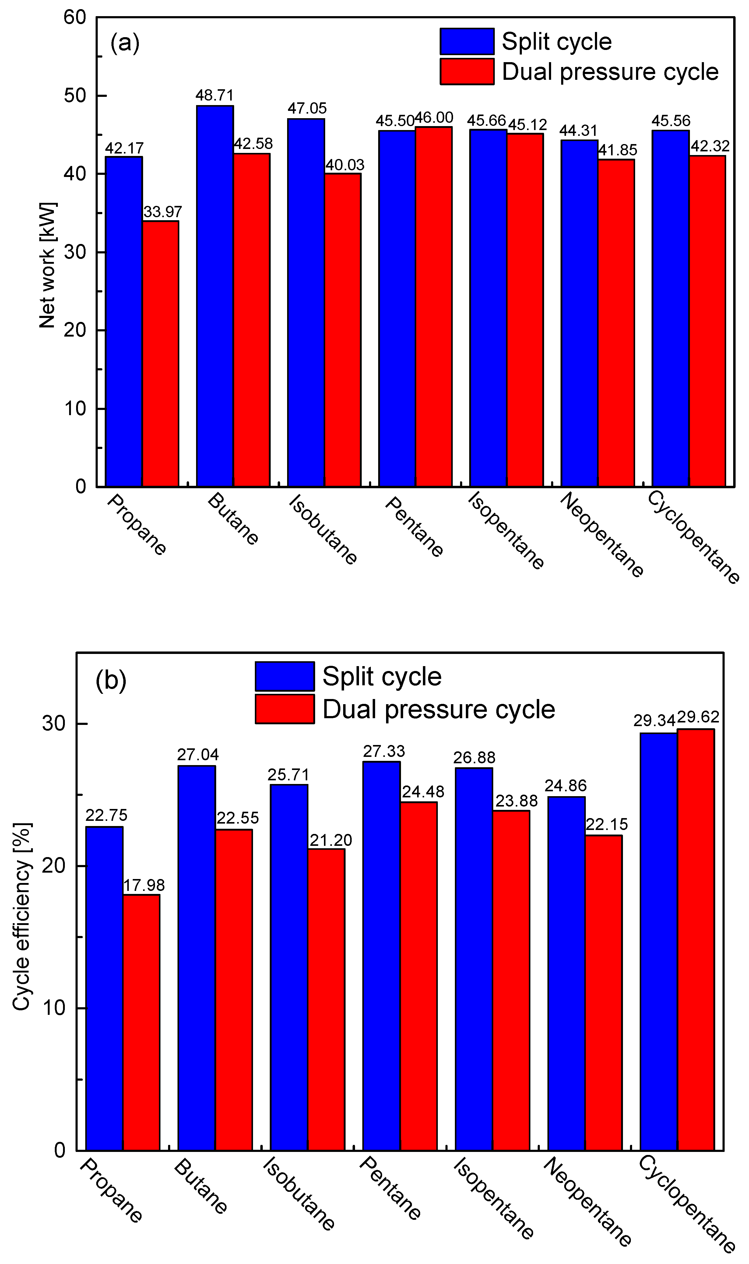
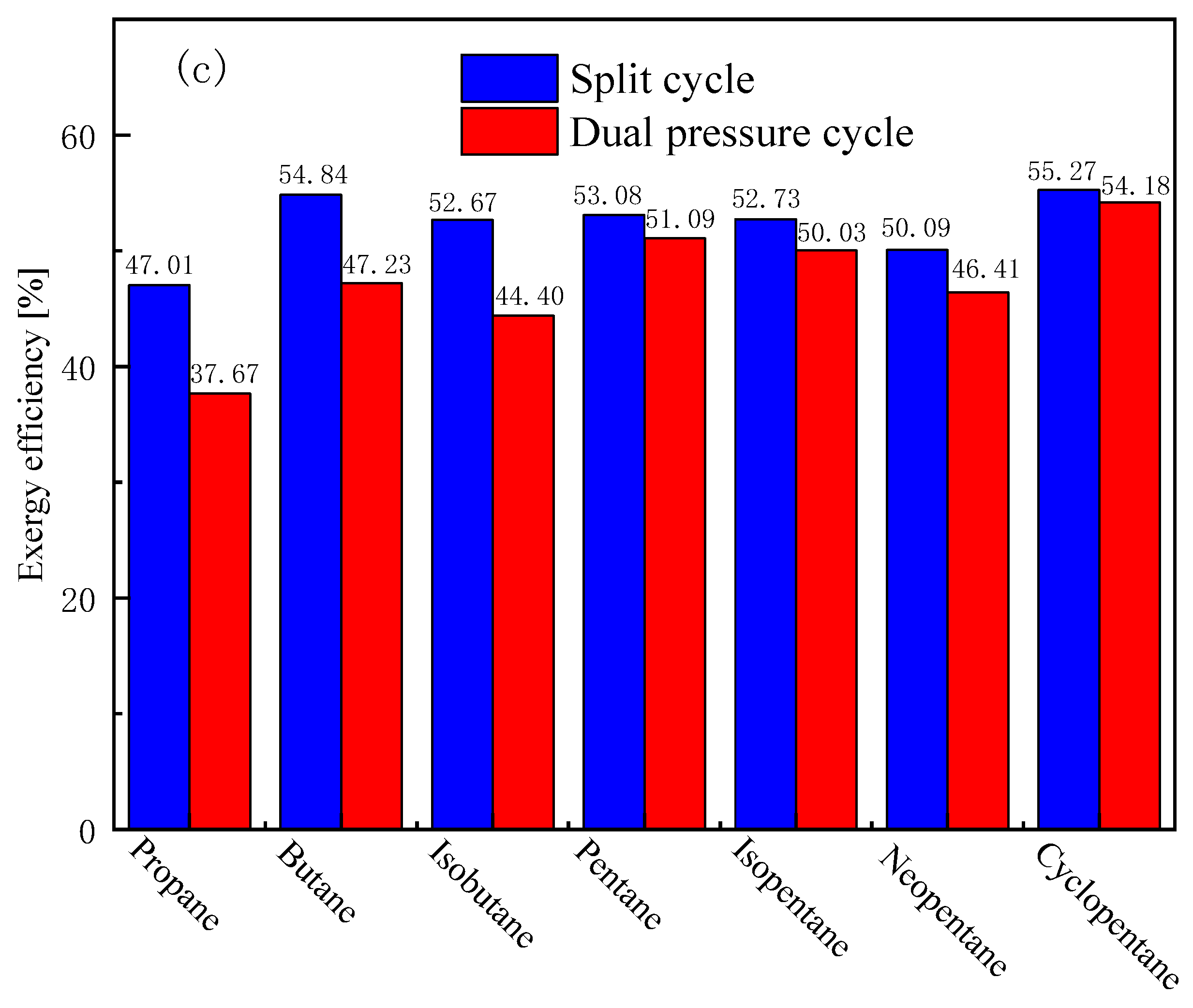
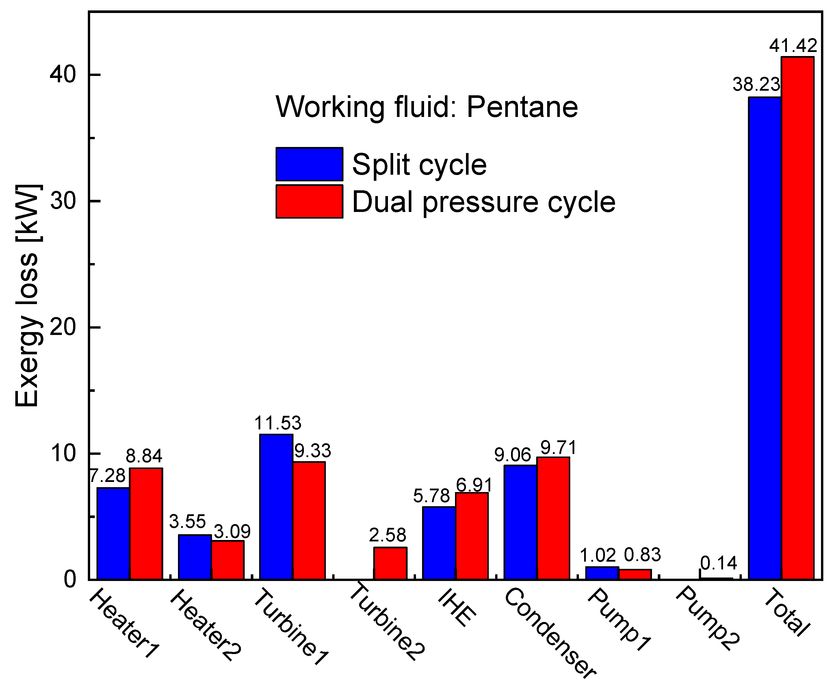
5.1. Cycle Analysis and Performance Comparison under Design Conditions
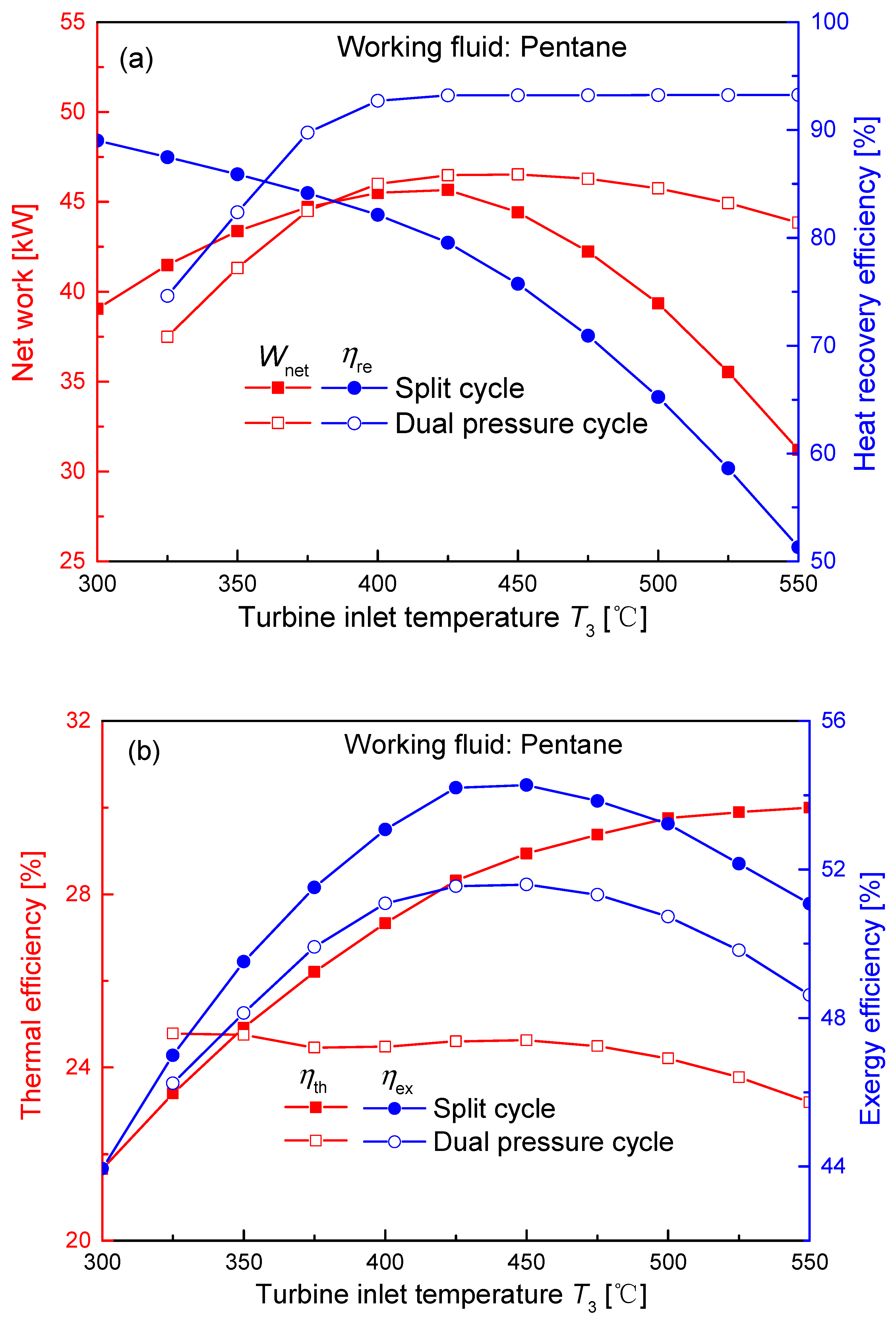
5.2. Effect of Turbine Inlet Temperature on Cycle Performances
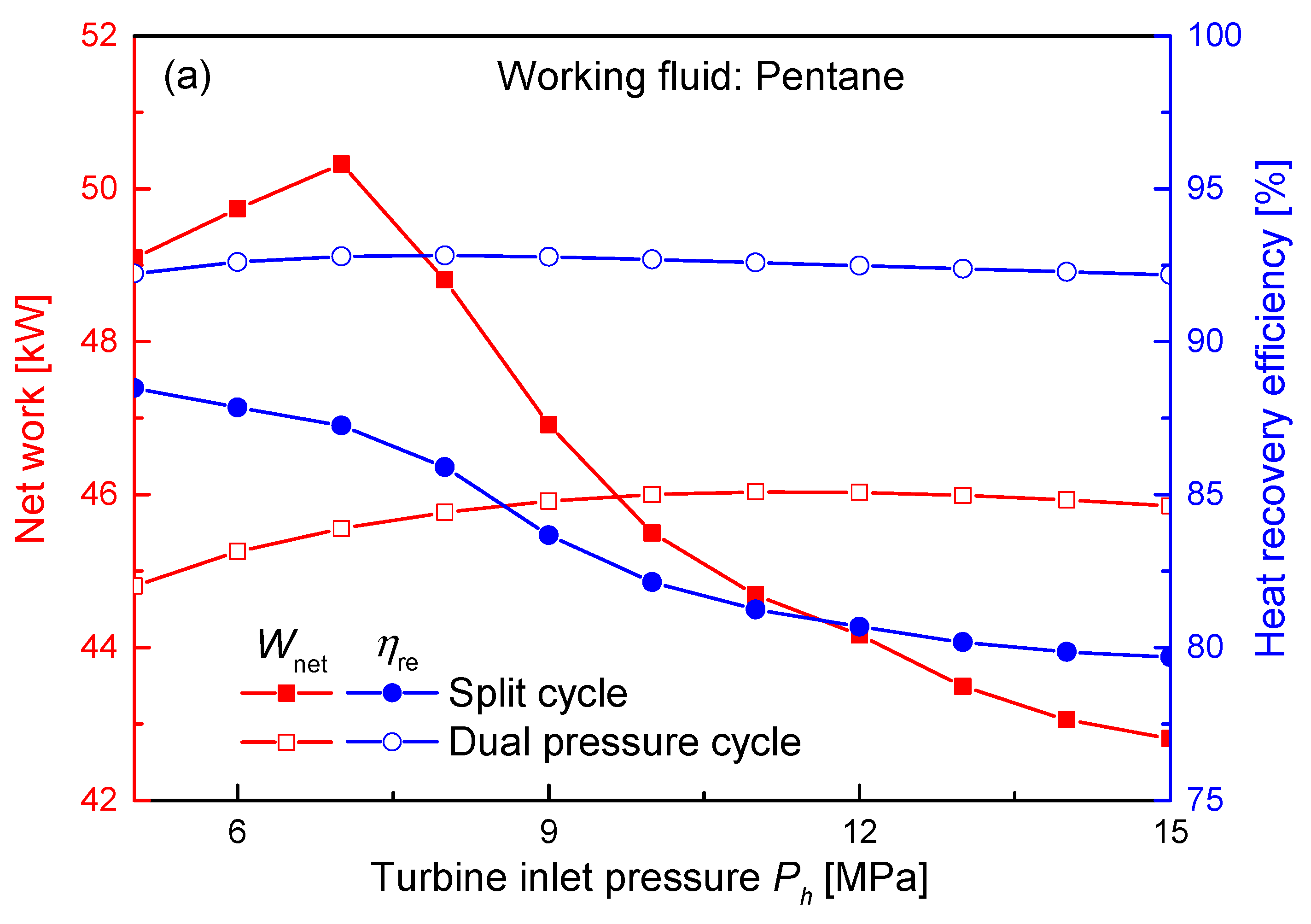
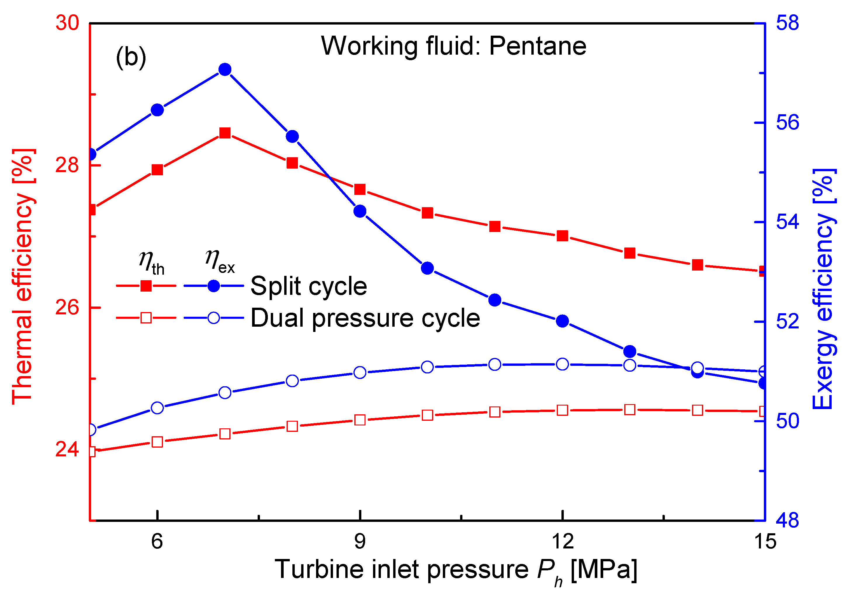
5.3. Effect of Turbine Inlet Pressure on Cycle Performances
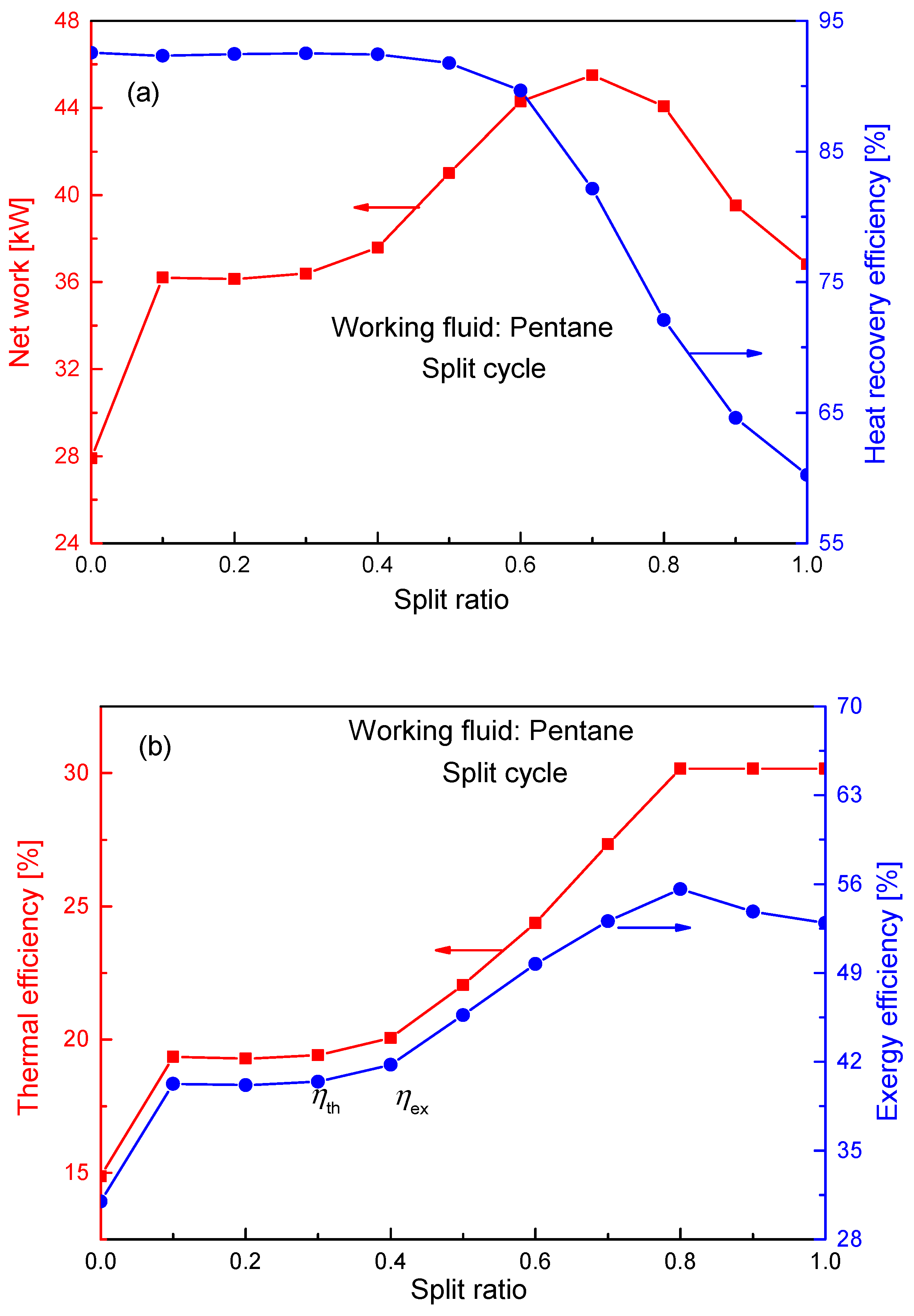
5.4. Effect of Split Ratio on Performances of Split Cycle
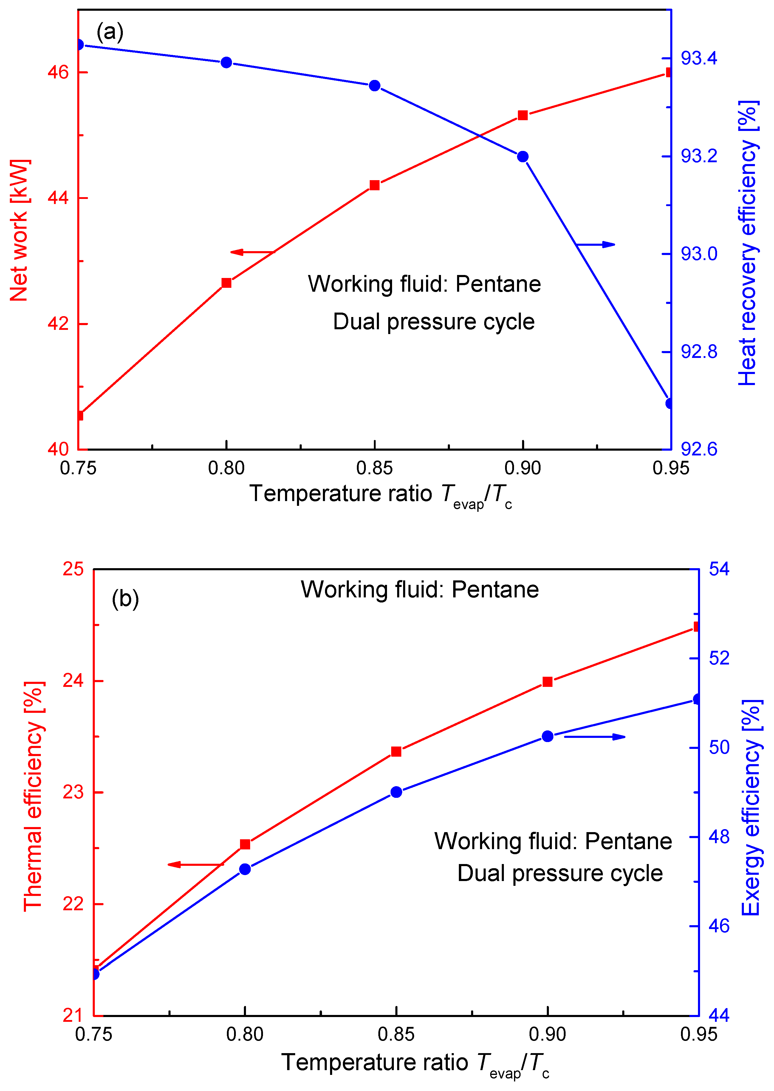
5.5. Effect of Evaporation Temperature on Performances of Dual Pressure Cycle
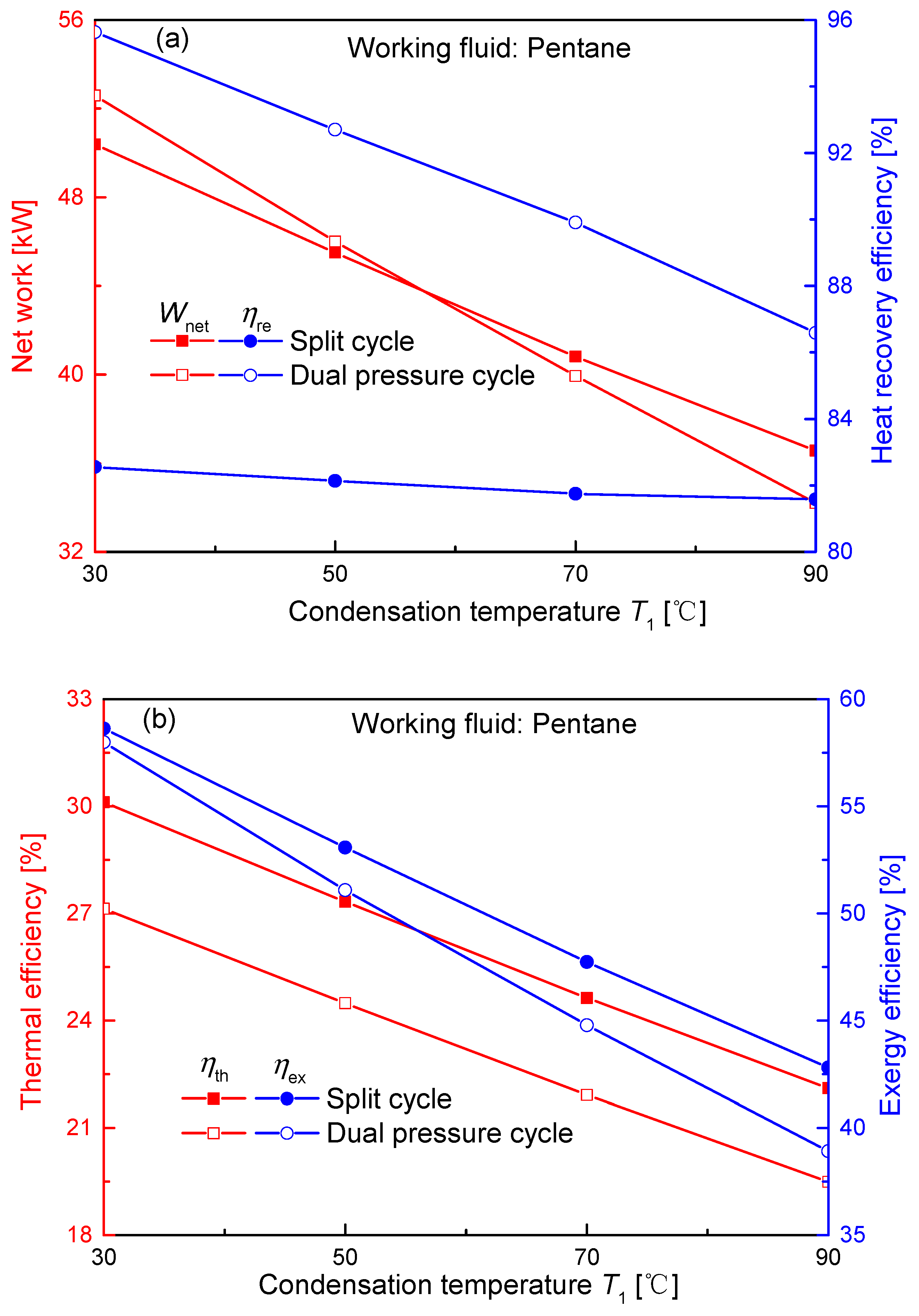
5.6. Effect of Condensation Temperatures on Cycle Performances
5.7. Effect of Turbomachinery Efficiency on Cycle Performances
5.8. Parametric Optimization
6. Conclusions
- (1)
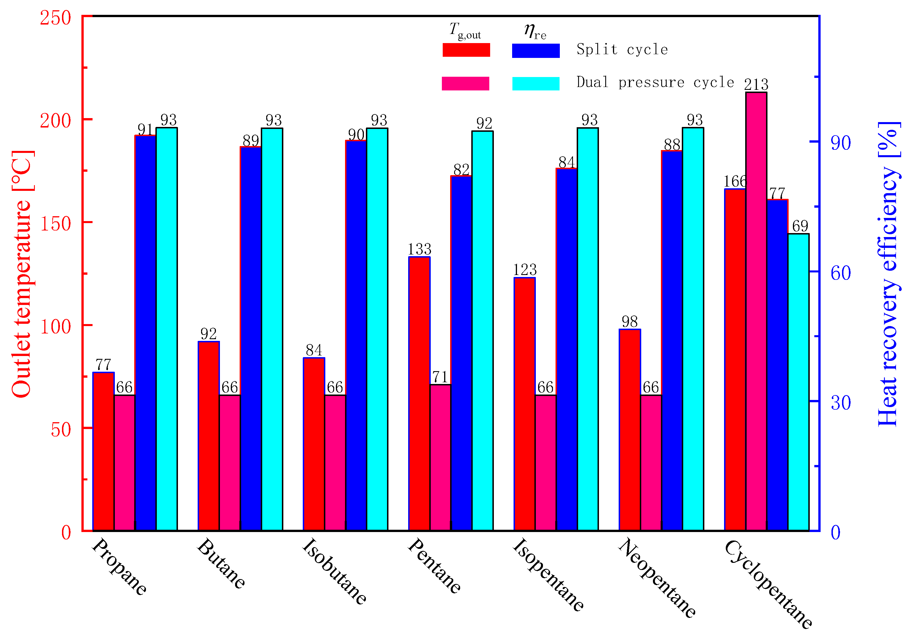
- Under design conditions, the dual pressure cycle can extract more waste heat than the split cycle for most high-temperature fluids. However, a higher net work is generally achieved by the split cycle. Among the considered fluids, the highest work 48.71 kW, is obtained by the split cycle with butane.
- (2)
- As the turbine inlet temperature increases, the net work of considered two cycles first increases and then decreases. Meanwhile, with the turbine inlet pressure increasing, net work of split cycle first goes up and then decreases, while the work of dual pressure cycle increases slowly.
- (3)
- For the split cycle, an optimal split ratio exists to get the maximum network. For the dual pressure cycle, as the evaporation temperature increases, performances except recovery efficiency increases. Furthermore, with the condensation temperature increasing and the turbomachinery efficiency decreasing, thermodynamic performances including net work and efficiency have different reduction degrees.
- (4)
- For the selected seven working fluids, optimized net works are in the range 46.51~49.96 kW for the split cycle. The highest work is obtained by pentane, while the lowest work is achieved by propane. As for the dual pressure cycle, the work range is 36.04~52.05 kW. The minimum and maximum values are, respectively, obtained by propane and cyclopentane. At the same fluid except cyclopentane, split cycle always has a higher work than dual pressure cycle. Meanwhile, with the advantage of fewer components, split cycle is recommended to recover the waste heat of ICE.
Author Contributions
Funding
Institutional Review Board Statement
Informed Consent Statement
Data Availability Statement
Conflicts of Interest
Nomenclature
| Symbols | |
| h | Specific enthalpy (kJ/kg) |
| m | Mass flow rate (kg/s) |
| E | Exergy (kW) |
| I | Irreversibility or exergy destruction rate (kW) |
| M | Molecular weight (g/mol) |
| P | Pressure (MPa) |
| Q | Heat transfer rate (kW) |
| s | Entropy (kJ/(kg·K)) |
| T | Temperature (K or °C) |
| W | Work down, power (kW) |
| Greeks | |
| η | Efficiency (%) |
| Δ | Difference |
| Abbreviations | |
| GA | Genetic algorithm |
| ICE | Internal combustion engine |
| IHE | Internal heat exchanger |
| ORC | Organic Rankine cycle |
| HT | How-temperature |
| LT | Low-temperature |
| SR | Split ratio |
| PPTD | Pinch point temperature difference |
| S-CO2 | Supercritical carbon dioxide |
| Subscripts and superscripts | |
| c | Critical state |
| C | Condenser |
| Con | Condensation |
| Com | compressor |
| f | Working fluid |
| g | Exhaust gas |
| H1 | Heater 1 |
| H2 | Hever 2 |
| T1 | Turbine 1 |
| T2 | Turbine 2 |
| P1 | Pump 1 |
| P2 | Pump 2 |
| h | High pressure |
| i | A state point of a cycle |
| in | Inlet temperature of gas |
| mid | Temperature at the outlet of Heater1 |
| net | Net value |
| evap | Evaporation |
| out | Outlet temperature of gas |
| ex | Exergy |
| re | Recovery |
| th | Thermodynamic |
| 1,…8 | Thermodynamic state points |
Appendix A

| Working Fluid | Structure | M (g/mol) | Tc (°C) | Pc (kPa) | Pcon at 50 °C (kPa) |
|---|---|---|---|---|---|
| Ethane | CH3CH3 | 30.07 | 32.17 | 4872.20 | ---- |
| Propane | CH3CH2CH3 | 44.10 | 96.74 | 4251.20 | 1713.30 |
| Butane | CH3-2(CH2)-CH3 | 58.12 | 151.98 | 3796.00 | 495.75 |
| Isobutane | CH(CH3)3 | 58.12 | 134.66 | 3629.00 | 684.90 |
| Pentane | CH3-3(CH2)-CH3 | 72.15 | 196.55 | 3370.00 | 159.25 |
| Isopentane | (CH3)2CHCH2CH3 | 72.15 | 187.20 | 3378.00 | 205.51 |
| Neopentane | C(CH3)4 | 72.15 | 160.59 | 3196.00 | 355.80 |
| Cyclopentane | C5H10 | 70.13 | 238.57 | 4571.20 | 103.83 |
| Isohexane | (CH3)2CH(CH2)2CH3 | 86.18 | 224.55 | 3040.00 | 72.33 |
| Hexane | CH3-4(CH2)-CH3 | 86.18 | 234.67 | 3034.00 | 54.09 |
| Cyclohexane | C6H12 | 84.16 | 280.45 | 4080.50 | 36.27 |
| Heptane | CH3-5(CH2)-CH3 | 100.20 | 266.98 | 2736.00 | 18.88 |
| Octane | CH3-6(CH2)-CH3 | 114.23 | 296.17 | 2497.00 | 6.68 |
| Nonane | CH3-7(CH2)-CH3 | 128.26 | 321.40 | 2281.00 | 2.42 |
| Decane | CH3-8(CH2)-CH3 | 142.28 | 344.55 | 2103.00 | 0.88 |
| Dodecane | CH3-10(CH2)-CH3 | 170.33 | 384.95 | 1817.00 | 0.12 |
| Benzene | C6H6 | 78.11 | 288.87 | 4907.30 | 36.20 |
| Toluene | CH3-C6H5 | 92.14 | 318.60 | 4126.30 | 12.29 |
| Methylcyclohexane | C6H11-CH3 | 98.19 | 299.05 | 3470.00 | 18.44 |
| Ethyl benzene | C8H10 | 106.17 | 343.97 | 3622.40 | 4.69 |
| m-xylene | C8H10-1.3-dimethylbenzene | 106.17 | 343.74 | 3534.60 | 4.16 |
| p-xylene | C8H10-1.4-dimethylbenzene | 106.17 | 343.02 | 3531.50 | 4.35 |
| MM | C6H18OSI2 | 162.38 | 245.60 | 1939.00 | 17.49 |
| MDM | C8H24O2SI3 | 236.53 | 290.94 | 1415.00 | 2.19 |
| MD2M | C10H30 O3SI4 | 310.69 | 326.25 | 1227.00 | 0.33 |
| MD3M | C12H36 O4SI5 | 384.84 | 355.21 | 945.00 | 0.05 |
| MD4M | C14H42 O5SI6 | 458.99 | 380.05 | 877.00 | 0.00 |
| D4 | C8H24O4SI4 | 296.62 | 313.35 | 1332.00 | 0.70 |
| D5 | C10H30 O5SI5 | 370.77 | 346.00 | 1160.00 | 0.15 |
| D6 | C12H36 O6SI6 | 444.92 | 372.63 | 961.00 | 0.03 |
| Methanol | CH3OH | 32.04 | 239.45 | 8103.50 | 55.68 |
| Ethanol | C2H6O | 46.07 | 241.56 | 6268.00 | 29.41 |
| Acetone | (CH3)2CO | 58.08 | 234.95 | 4700.00 | 81.95 |
References
- Zhang, R.; Su, W.; Lin, X.; Zhou, N.; Zhao, L. Thermodynamic analysis and parametric optimization of a novel S–CO2 power cycle for the waste heat recovery of internal combustion engines. Energy 2020, 209, 118484. [Google Scholar] [CrossRef]
- Zhu, S.; Zhang, K.; Deng, K. A review of waste heat recovery from the marine engine with highly efficient bottoming power cycles. Renew. Sustain. Energy Rev. 2020, 120, 109611. [Google Scholar] [CrossRef]
- Lan, Q.; Bai, Y.; Fan, L.; Gu, Y.; Wen, L.; Yang, L. Investigation on fuel injection quantity of low-speed diesel engine fuel system based on response surface prediction model. Energy 2020, 211, 118946. [Google Scholar] [CrossRef]
- Shi, L.; Shu, G.; Tian, H.; Deng, S. A review of modified Organic Rankine cycles (ORCs) for internal combustion engine waste heat recovery (ICE-WHR). Renew. Sustain. Energy Rev. 2018, 92, 95–110. [Google Scholar] [CrossRef]
- Fraioli, V.; Beatrice, C.; Di Blasio, G.; Belgiorno, G.; Migliaccio, M. Multidimensional Simulations of Combustion in Methane-Diesel Dual-Fuel Light-Duty Engines; SAE International: Warrendale, PA, USA, 2017. [Google Scholar]
- Xu, B.; Li, X. A Q-learning based transient power optimization method for organic Rankine cycle waste heat recovery system in heavy duty diesel engine applications. Appl. Energy 2021, 286, 116532. [Google Scholar] [CrossRef]
- Hernandez, A.; Ruiz, F.; Gusev, S.; De Keyser, R.; Quoilin, S.; Lemort, V. Experimental validation of a multiple model predictive control for waste heat recovery organic Rankine cycle systems. Appl. Therm. Eng. 2021, 193, 116993. [Google Scholar] [CrossRef]
- Peralez, J.; Nadri, M.; Dufour, P.; Tona, P.; Sciarretta, A. Organic Rankine Cycle for Vehicles: Control Design and Experimental Results. IEEE Trans. Control Syst. Technol. 2017, 25, 952–965. [Google Scholar] [CrossRef] [Green Version]
- Zhang, Y.-Q.; Wu, Y.; Xia, G.; Ma, C.-F.; Ji, W.-N.; Liu, S.-W.; Yang, K.; Yang, F.-B. Development and experimental study on organic Rankine cycle system with single-screw expander for waste heat recovery from exhaust of diesel engine. Energy 2014, 77, 499–508. [Google Scholar] [CrossRef]
- Liu, P.; Shu, G.; Tian, H. Carbon Dioxide as Working Fluids in Transcritical Rankine Cycle for Diesel Engine Multiple Waste Heat Recovery in Comparison to Hydrocarbons. J. Therm. Sci. 2019, 28, 494–504. [Google Scholar] [CrossRef]
- Yağlı, H.; Koç, Y.; Koç, A.; Görgülü, A.; Tandiroğlu, A. Parametric optimization and exergetic analysis comparison of subcritical and supercritical organic Rankine cycle (ORC) for biogas fuelled combined heat and power (CHP) engine exhaust gas waste heat. Energy 2016, 111, 923–932. [Google Scholar] [CrossRef]
- Yang, M.H. Optimizations of the waste heat recovery system for a large marine diesel engine based on transcritical Rankine cycle. Energy 2016, 113, 1109–1124. [Google Scholar] [CrossRef]
- Yang, M.H.; Yeh, R.H. Economic research of the transcritical Rankine cycle systems to recover waste heat from the marine medium-speed diesel engine. Appl. Therm. Eng. 2017, 114, 1343–1354. [Google Scholar] [CrossRef]
- Tian, H.; Liu, P.; Shu, G. Challenges and opportunities of Rankine cycle for waste heat recovery from internal combustion engine. Prog. Energy Combust. Sci. 2021, 84, 100906. [Google Scholar] [CrossRef]
- Shu, G.; Shi, L.; Tian, H.; Deng, S.; Li, X.; Chang, L. Configurations selection maps of CO2-based transcritical Rankine cycle (CTRC) for thermal energy management of engine waste heat. Appl. Energy 2017, 186, 423–435. [Google Scholar] [CrossRef]
- Li, L.; Tian, H.; Liu, P.; Shi, L.; Shu, G. Optimization of CO2 Transcritical Power Cycle (CTPC) for engine waste heat recovery based on split concept. Energy 2021, 229, 120718. [Google Scholar] [CrossRef]
- Tian, H.; Liu, L.; Shu, G.; Wei, H.; Liang, X. Theoretical research on working fluid selection for a high-temperature regenerative transcritical dual-loop engine organic Rankine cycle. Energy Convers. Manag. 2014, 86, 764–773. [Google Scholar] [CrossRef]
- Song, J.; Li, X.; Wang, K.; Markides, C.N. Parametric optimisation of a combined supercritical CO2 (S-CO2) cycle and organic Rankine cycle (ORC) system for internal combustion engine (ICE) waste-heat recovery. Energy Convers. Manag. 2020, 218, 112999. [Google Scholar] [CrossRef]
- Di Battista, D.; Fatigati, F.; Carapellucci, R.; Cipollone, R. An improvement to waste heat recovery in internal combustion engines via combined technologies. Energy Convers. Manag. 2021, 232, 113880. [Google Scholar] [CrossRef]
- Chen, T.; Zhuge, W.; Zhang, Y.; Zhang, L. A novel cascade organic Rankine cycle (ORC) system for waste heat recovery of truck diesel engines. Energy Convers. Manag. 2017, 138, 210–223. [Google Scholar] [CrossRef]
- Liu, P.; Shu, G.; Tian, H. How to approach optimal practical Organic Rankine cycle (OP-ORC) by configuration modification for diesel engine waste heat recovery. Energy 2019, 174, 543–552. [Google Scholar] [CrossRef]
- Grelet, V.; Reiche, T.; Lemort, V.; Nadri, M.; Dufour, P. Transient performance evaluation of waste heat recovery rankine cycle based system for heavy duty trucks. Appl. Energy 2016, 165, 878–892. [Google Scholar] [CrossRef]
- Dai, X.; Shi, L.; Qian, W. Review of the working fluid thermal stability for Organic Rankine Cycles. J. Therm. Sci. 2019, 28, 597–607. [Google Scholar] [CrossRef]
- Benato, A.; Kærn, M.R.; Pierobon, L.; Stoppato, A.; Haglind, F. Analysis of hot spots in boilers of organic Rankine cycle units during transient operation. Appl. Energy 2015, 151, 119–131. [Google Scholar] [CrossRef]
- Wang, X.; Tian, H.; Shu, G. Part-Load Performance Prediction and Operation Strategy Design of Organic Rankine Cycles with a Medium Cycle Used for Recovering Waste Heat from Gaseous Fuel Engines. Energies 2016, 9, 10. [Google Scholar] [CrossRef]
- Shu, G.; Zhao, M.; Tian, H.; Wei, H.; Liang, X.; Huo, Y.; Zhu, W. Experimental investigation on thermal OS/ORC (Oil Storage/Organic Rankine Cycle) system for waste heat recovery from diesel engine. Energy 2016, 107, 693–706. [Google Scholar] [CrossRef]
- Shu, G.; Li, X.; Tian, H.; Liang, X.; Wei, H.; Wang, X. Alkanes as working fluids for high-temperature exhaust heat recovery of diesel engine using organic Rankine cycle. Appl. Energy 2014, 119, 204–217. [Google Scholar] [CrossRef]
- Shu, G.; Liu, L.; Tian, H.; Wei, H.; Liang, Y. Analysis of regenerative dual-loop organic Rankine cycles (DORCs) used in engine waste heat recovery. Energy Convers. Manag. 2013, 76, 234–243. [Google Scholar] [CrossRef]
- Li, X.; Shu, G.; Tian, H.; Huang, G.; Liu, P.; Wang, X.; Shi, L. Experimental comparison of dynamic responses of CO2 transcritical power cycle systems used for engine waste heat recovery. Energy Convers. Manag. 2018, 161, 254–265. [Google Scholar] [CrossRef]
- Pan, L.; Shi, W.; Wei, X.; Li, T.; Li, B. Experimental verification of the self-condensing CO2 transcritical power cycle. Energy 2020, 198, 117335. [Google Scholar] [CrossRef]
- Wang, M.; Zhang, J.; Zhao, S.; Liu, Q.; Zhao, Y.; Wu, H. Performance investigation of transcritical and dual-pressure Organic Rankine Cycles from the aspect of thermal match. Energy Convers. Manag. 2019, 197, 111850. [Google Scholar] [CrossRef]
- Zhang, Q.; Luo, Z.; Zhao, Y.; Pavel, S. Thermodynamic analysis and multi-objective optimization of a transcritical CO2 waste heat recovery system for cruise ship application. Energy Convers. Manag. 2021, 227, 113612. [Google Scholar] [CrossRef]
- Houck, C.R.; Joines, J.; Kay, M.G. A genetic algorithm for function optimization: A Matlab implementation. NCSU.IE. TR 2008, 9, 95. [Google Scholar]
- Van Kleef, L.M.T.; Oyewunmi, O.A.; Markides, C.N. Multi-objective thermo-economic optimization of organic Rankine cycle (ORC) power systems in waste-heat recovery applications using computer-aided molecular design techniques. Appl. Energy 2019, 251, 112513. [Google Scholar] [CrossRef]
- Jankowski, M.; Borsukiewicz, A.; Wiśniewski, S.; Hooman, K. Multi-objective analysis of an influence of a geothermal water salinity on optimal operating parameters in low-temperature ORC power plant. Energy 2020, 202, 117666. [Google Scholar] [CrossRef]
- Razmi, A.R.; Arabkoohsar, A.; Nami, H. Thermoeconomic analysis and multi-objective optimization of a novel hybrid absorption/recompression refrigeration system. Energy 2020, 210, 118559. [Google Scholar] [CrossRef]
- Liu, X.; Nguyen, M.Q.; He, M. Performance analysis and optimization of an electricity-cooling cogeneration system for waste heat recovery of marine engine. Energy Convers. Manag. 2020, 214, 112887. [Google Scholar] [CrossRef]
- Balafkandeh, S.; Zare, V.; Gholamian, E. Multi-objective optimization of a tri-generation system based on biomass gasification/digestion combined with S-CO2 cycle and absorption chiller. Energy Convers. Manag. 2019, 200, 112057. [Google Scholar] [CrossRef]
- Lemmon, E.W.; Bell, I.H.; Huber, M.L.; McLinden, M.O. NIST Standard Reference Database 23, Reference Fluid Thermodynamic and Transport Properties-REFPROP, Version 10.0, National Institute of Standards and Technology; Standard Reference Data Program: Gaithersburg, MD, USA, 2018. [Google Scholar]


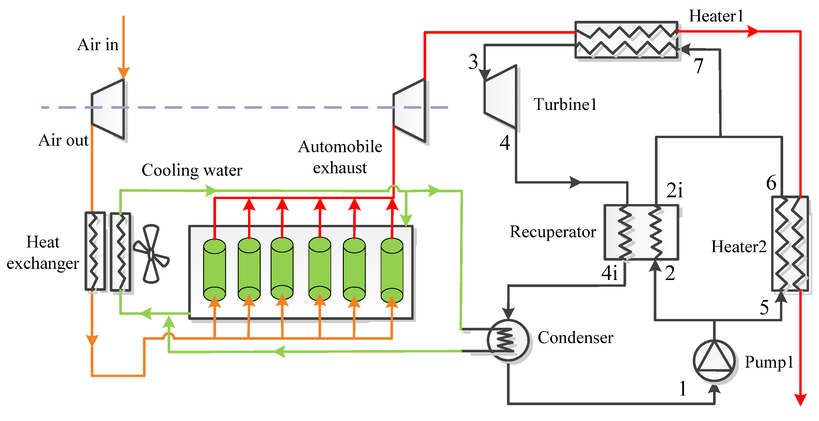


| Cycle | Schematic Diagram of the Cycle |
|---|---|
| Recuperative cycle | 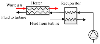 |
| Split cycle |  |
| Combined cycle | 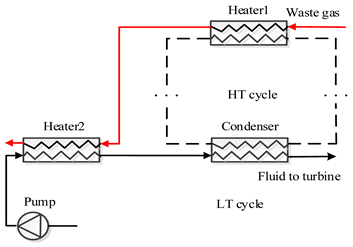 |
| Dual pressure cycle | 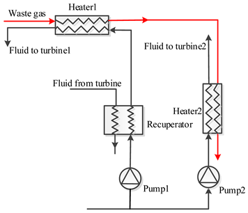 |
| Components | Energy Models | Exergy Destruction |
|---|---|---|
| Heater1 | ; | |
| Turbine1 | = | |
| Recuperator | ||
| Heater2 | ||
| Condenser | ||
| Pump1 | = |
| Components | Energy Models | Exergy Destruction |
|---|---|---|
| Heater1 | ||
| Turbine1 | = | |
| Recuperator | ||
| Heater2 | ||
| Turbine2 | = | |
| Condenser | ||
| Pump1 | = | |
| Pump2 | = |
| Parameters | Values | Gas Components | Mass Fraction (%) |
|---|---|---|---|
| Power output | 258 kW | CO2 | 12.06 |
| Engine displacement | 8.9 L | H2O | 1.91 |
| Input temperature of exhaust gas | 600 °C | N2 | 75.45 |
| Mass flow of exhaust gas | 0.3250 kg/s | O2 | 10.58 |
| Exhaust gas pressure | 0.1 MPa |
| Working Fluid | Tc (°C) | Pc (kPa) | Condensation Pressure (kPa) | ||
|---|---|---|---|---|---|
| 30 °C | 50 °C | 90 °C | |||
| Propane | 96.74 | 4251.20 | 1079.00 | 1713.30 | 3764.10 |
| Butane | 151.98 | 3796.00 | 283.41 | 495.75 | 1249.30 |
| Isobutane | 134.66 | 3629.00 | 404.72 | 684.90 | 1642.00 |
| Pentane | 196.55 | 3370.00 | 81.99 | 159.25 | 470.34 |
| Isopentane | 187.20 | 3378.00 | 109.17 | 205.51 | 578.61 |
| Neopentane | 160.59 | 3196.00 | 200.57 | 355.80 | 913.23 |
| Cyclopentane | 238.57 | 4571.20 | 51.36 | 103.83 | 326.33 |
| Design Parameters | Set Value | Range of Variation |
|---|---|---|
| Turbine inlet temperature T3 | 400 °C | 300~550 °C |
| Turbine inlet pressure P3 | 10 MPa | 5~15 MPa |
| Condensation temperature T1 | 50 °C | 30 °C, 50 °C, 70 °C, 90 °C |
| SR for split cycle | 0.7 | 0~1 |
| Evaporation temperature for dual pressure cycle | 0.95 Tc | 0.75 Tc~0.95 Tc |
| Superheat temperature for dual pressure cycle | 5 °C | --- |
| PPTD in Heater1 | 15 °C | --- |
| PPTD in Heater2 | 15 °C | --- |
| PPTD in recuperator | 15 °C | --- |
| Pump efficiency | 0.8 | 0.5~0.9 |
| Turbine efficiency | 0.7 | 0.5~0.9 |
| Pump Efficiency | Split Cycle | Dual Pressure Cycle | ||||
|---|---|---|---|---|---|---|
| Net Work (kW) | Heat Recovery Efficiency (%) | Thermal Efficiency (%) | Net Work (kW) | Heat Recovery Efficiency (%) | Thermal Efficiency (%) | |
| 0.5 | 42.20 | 81.64 | 25.50 | 43.46 | 92.71 | 23.13 |
| 0.6 | 43.78 | 81.91 | 26.37 | 44.61 | 92.68 | 23.75 |
| 0.7 | 44.91 | 82.10 | 26.99 | 45.43 | 92.67 | 24.19 |
| 0.8 | 45.75 | 82.25 | 27.45 | 46.04 | 92.65 | 24.52 |
| 0.9 | 46.19 | 82.23 | 27.71 | 46.52 | 92.65 | 24.77 |
| Turbine Efficiency | Split Cycle | Dual Pressure Cycle | ||||
|---|---|---|---|---|---|---|
| Net Work (kW) | Heat Recovery Efficiency (%) | Thermal Efficiency (%) | Net Work (kW) | Heat Recovery Efficiency (%) | Thermal Efficiency (%) | |
| 0.5 | 35.37 | 86.30 | 20.22 | 36.61 | 93.22 | 19.38 |
| 0.6 | 40.71 | 83.90 | 23.94 | 41.52 | 93.18 | 21.99 |
| 0.7 | 45.76 | 82.25 | 27.45 | 46.04 | 92.65 | 24.52 |
| 0.8 | 50.19 | 80.91 | 30.61 | 50.34 | 92.12 | 26.96 |
| 0.9 | 54.33 | 79.95 | 33.53 | 54.48 | 91.71 | 29.31 |
| Parameters | Propane | Butane | Isobutane | Pentane | Isopentane | Neopentane | Cyclopentane |
|---|---|---|---|---|---|---|---|
| T3 (°C) | 398.00 | 384.83 | 387.49 | 420.81 | 418.81 | 381.73 | 427.90 |
| Ph (MPa) | 10.11 | 9.04 | 7.95 | 6.17 | 7.12 | 7.50 | 7.35 |
| SR | 0.74 | 0.71 | 0.74 | 0.66 | 0.71 | 0.76 | 0.68 |
| Tg,out (°C) | 77.65 | 87.90 | 82.33 | 90.08 | 112.59 | 101.77 | 146.07 |
| mf (kg/s) | 0.39 | 0.34 | 0.40 | 0.30 | 0.31 | 0.39 | 0.25 |
| Wnet (kW) | 46.51 | 49.86 | 49.72 | 49.96 | 49.22 | 48.36 | 49.75 |
| ηth (%) | 25.12 | 27.44 | 27.09 | 27.60 | 28.38 | 27.31 | 30.69 |
| ηr (%) | 91.35 | 89.65 | 90.57 | 89.29 | 85.56 | 87.36 | 79.99 |
| ηex (%) | 51.87 | 55.96 | 55.61 | 56.15 | 56.29 | 54.82 | 58.87 |
| Parameters | Propane | Butane | Isobutane | Pentane | Isopentane | Neopentane | Cyclopentane |
|---|---|---|---|---|---|---|---|
| T3 (°C) | 400.30 | 430.88 | 425.89 | 450.87 | 440.31 | 416.95 | 516.26 |
| Ph (MPa) | 15.00 | 15.00 | 15.00 | 15.00 | 15.00 | 15.00 | 15.00 |
| Tevap/Tc | 0.95 | 0.95 | 0.95 | 0.95 | 0.95 | 0.95 | 0.95 |
| Tg,out (°C) | 66.33 | 66.59 | 66.42 | 66.31 | 66.34 | 66.31 | 66.55 |
| mf1 (kg/s) | 0.25 | 0.20 | 0.22 | 0.19 | 0.20 | 0.23 | 0.15 |
| mf2 (kg/s) | 0.22 | 0.17 | 0.21 | 0.15 | 0.16 | 0.19 | 0.16 |
| Wnet (kW) | 36.04 | 43.33 | 40.72 | 46.81 | 45.63 | 42.15 | 52.05 |
| ηth (%) | 19.08 | 22.94 | 21.56 | 24.78 | 24.15 | 22.31 | 27.56 |
| ηr (%) | 93.21 | 93.17 | 93.20 | 93.22 | 93.21 | 93.22 | 93.18 |
| ηex (%) | 39.97 | 48.05 | 45.16 | 51.91 | 50.60 | 46.74 | 57.73 |
Publisher’s Note: MDPI stays neutral with regard to jurisdictional claims in published maps and institutional affiliations. |
© 2021 by the authors. Licensee MDPI, Basel, Switzerland. This article is an open access article distributed under the terms and conditions of the Creative Commons Attribution (CC BY) license (https://creativecommons.org/licenses/by/4.0/).
Share and Cite
Lin, X.; Chen, C.; Yu, A.; Yin, L.; Su, W. Performance Comparison of Advanced Transcritical Power Cycles with High-Temperature Working Fluids for the Engine Waste Heat Recovery. Energies 2021, 14, 5886. https://doi.org/10.3390/en14185886
Lin X, Chen C, Yu A, Yin L, Su W. Performance Comparison of Advanced Transcritical Power Cycles with High-Temperature Working Fluids for the Engine Waste Heat Recovery. Energies. 2021; 14(18):5886. https://doi.org/10.3390/en14185886
Chicago/Turabian StyleLin, Xinxing, Chonghui Chen, Aofang Yu, Likun Yin, and Wen Su. 2021. "Performance Comparison of Advanced Transcritical Power Cycles with High-Temperature Working Fluids for the Engine Waste Heat Recovery" Energies 14, no. 18: 5886. https://doi.org/10.3390/en14185886
APA StyleLin, X., Chen, C., Yu, A., Yin, L., & Su, W. (2021). Performance Comparison of Advanced Transcritical Power Cycles with High-Temperature Working Fluids for the Engine Waste Heat Recovery. Energies, 14(18), 5886. https://doi.org/10.3390/en14185886