Article

Thermoplastic RTM: Impact Properties of Anionically Polymerised Polyamide 6 Composites for Structural Automotive Parts

1
School of Engineering, Institute for Materials and Processes, Sanderson Building, The University of Edinburgh, Robert Stevenson Road, Edinburgh EH9 3FB, Scotland, UK
2
Centre for Advanced Composite Materials, Department of Mechanical Engineering, University of Auckland, Gate 3, 314-390 Khyber Pass Road, Newmarket, Auckland 1023, New Zealand
3
Johns Manville Europe GmbH, Werner-Schuller-Str.1, 97877 Wertheim, Germany
*
Author to whom correspondence should be addressed.
Energies 2021, 14(18), 5790; https://doi.org/10.3390/en14185790
Submission received: 28 July 2021 / Revised: 31 August 2021 / Accepted: 6 September 2021 / Published: 14 September 2021
(This article belongs to the Special Issue Advanced Thermoplastic Composites)

Abstract

:
This study investigates the impact behaviour and post-impact performance of polyamide-6 glass fibre reinforced composites, manufactured by thermoplastic resin transfer moulding. Impact test samples were extracted from quasi-isotropic laminates using two different glass fibre sizings, both with a fibre volume fraction of approximately 52%. A previous study showed that one of these sizings enhanced the interfacial strength and Mode I fracture toughness; however, the effects of the sizing on out-of-plane impact is of greater significance in terms of automotive applications. A drop-weight impact tester was used to determine out-of-plane impact performance for both sizings in terms of impact load-induced and energy returned from the striker. High-speed video of the impact response was simultaneously captured. Testing was carried out at three impact energy levels: two sub-penetration and one full penetration. The impact damage area was observed, and the post-damage compression properties of samples were measured to determine the reduction in their strength and stiffness. Results showed that the use of different sizing technologies had little effect on the post-impact compressive properties and that penetration led to only a 29% drop in compression strength. Overall, the outcomes of this work demonstrate the potential of these materials in automotive applications.

1. Introduction

Polymers play an extremely important role in modern society and have transformed methods of production extensively, which have had profoundly positive effects in packaging, textiles, construction, consumer products, transportation and many other industries. This continuous growth of polymers is mainly due to their versatility, cheap cost, light weight and durability [1]. Within the aforementioned industries, thermoplastics are the most widely used polymers (~80%) due to their ability to be remelted, and their superior toughness properties compared with thermoset resins [2]. The opposite is true however in liquid composite moulding (LCM), where thermosets such as epoxies and polyurethanes are the standard matrix materials used. This is mainly due to their low viscosity, which means that they can be infused at relatively low pressures into fibre reinforcements with high fibre volume fractions (~50%) [3]. While such resins provide strong and stiff matrices, they generally tend to be brittle, with lower strain-to-failure and lower fracture toughness compared to thermoplastics [2]. In addition to this, they cannot be remelted, and therefore cannot be welded, reshaped or recycled. Fully polymerised thermoplastics cannot be processed via LCM because of their high viscosity, which makes it practically impossible for them to be infused into a high-volume fraction reinforcement material. Were it not for this, there would likely be significant demand for thermoplastics in such processes.
Within the automotive industry, composite materials have traditionally been associated with luxury or racing vehicles because of their high cost; however, due to increased demand for light-weighting to reduce CO2 emissions, and cheaper production/material costs, the use of composites in passenger vehicles is becoming increasingly popular [4,5,6]. In order to meet production demands in the passenger vehicle market, manufacturing processes must be able to output at least 100,000 parts per year [7]. With this in mind, fast LCM processes such as resin transfer moulding (RTM) are most suitable due to their high throughput [4]. As it stands, these types of processes are used primarily with thermoset resins for the aforementioned reasons.
Knowledge of the impact behaviour of materials is important where their applications in components could potentially be subject to high strain-rate loading. Impact performance metrics are an extremely important factor when choosing materials in automotive parts, and can greatly determine the extent of passenger injury in case of a collision [8]. High molecular weight thermoplastics are generally tougher, with larger strains-to-failure compared to thermosets. Therefore, their use as matrix materials in composites should also result in higher impact damage resistance [9]. Improving the energy absorption of a component without significantly sacrificing the static properties may prevent the spread of damage to other, more critical components and potentially save lives as a result. Additionally, absorbing energy over a greater length of time can result in reduced peak projectile deceleration forces which, in the case of vehicles, can reduce the extent of injury caused to passengers. Therefore, as well as quantifying the maximum load a material system can withstand under impact and the energy absorbed prior to failure, the relationship between these two should also be considered. This could take the form of a maximum applied load for a given applied or absorbed impact energy (in J/kN).
Murray et al. [10,11,12] developed an RTM process that allowed for the manufacture of thermoplastic composites with a polyamide-6 matrix, known as TP-RTM. This work built on research carried out at multiple institutions using similar resin systems with different LCM processing techniques [13,14,15,16,17,18,19,20,21]. The process was shown to have good potential for automotive part manufacture due to the low viscosity of the reactants, quick reaction times, cheap raw materials and a high performing matrix. The anionically polymerised polyamide-6 (APA-6) is subject to cold crystallisation. This results in degrees of crystallinity greater than 40%, which fall on the upper end of those normally found for melt-processed PA-6. While higher crystallinity results in increased stiffness and reduced water uptake (which enhances mechanical performance), it often causes the material to behave in a more brittle fashion, with poorer impact performance [22]. The crystallinity can be tailored to optimise impact performance, and the use of certain additives can alter the material behaviour profoundly [23].
Mechanical testing of the APA-6 material demonstrated that its strength and modulus values were close to that for a typical RTM epoxy but with a significantly higher strain-to-failure, indicating superior toughness [10]. While the material retains comparable static properties to conventional resins, the addition of improved energy absorption properties would make it a highly suitable candidate for high impact applications. Bessel et al. [24] found that in APA-6, increased molecular weight (achieved at higher polymerisation temperatures) resulted in a tougher material. Where the molecular weight is fixed, the toughness of the material depends almost entirely on the crystallinity. In this study, toughness was defined as the area under tensile stress-strain curves. Samples with a degree of crystallinity (DC) of 30% were shown to possess toughness values that were approximately four times the values at a DC of 40%. This demonstrates the importance of optimising crystallinity in APA-6 and encourages a cautious approach towards highly crystalline APA-6 produced by TP-RTM.
PA-6 can absorb up to 9.5 wt% moisture at 100% relative humidity, and up to 2.8 wt% at 50% relative humidity [22]. This can have detrimental effects on mechanical performance and can significantly reduce the glass transition temperature. Nevertheless, although the strength and modulus decrease with water absorption, the opposite is true for toughness. The Izod impact strength of PA-6 increases significantly with increased water absorption. Samples conditioned at 50% RH had Izod impact strengths that were almost double the impact strengths of the samples tested dry as moulded [22]. This effect is particularly pronounced for PA-6 due to its very hygroscopic behaviour.
As thermoplastics generally exhibit a high degree of elastic-plastic behaviour, they usually possess better impact properties than their thermoset counterparts [11,25]. Morphological reorganisation via significant chain stretching when loaded leads to larger strains-to-failure than for cross-linked thermosets. This means that more impact energy can be absorbed by the material in terms of plastic deformation [26,27]. A thermoplastic’s ability to plastically deform means that damage is generally very localised, and damage spread is limited. Due to greater molecular mobility, thermoplastics also often exhibit superior damping properties compared to thermosets, which are heavily cross-linked [28]. This damping effect also helps thermoplastics to better absorb energy on impact. The same is true for composites with thermoplastic matrices compared to those with thermoset matrices, albeit to a lesser degree [11].
Failure in composites is extremely complex due to their many layers (laminae) and fibre-matrix interfaces. This makes them highly susceptible to crack initiation and propagation along the interfaces. During impact, the most common failure mechanisms are delamination (due to Mode II shear), matrix cracking (due to transverse shear), and trans-fracture cracking (due to fibre rupture) [25]. Due to their high melt viscosities, it is difficult to wet out the fibres in thermoplastic composites without significant amounts of pressure. Thermoplastic resin transfer moulding overcomes this challenge due to the extremely low viscosity of the precursor materials and should result in greater impact performance as a result.
In this study, the impact performance of glass fibre/APA-6 composites, manufactured using two different fibre sizings, and tested at three different energy levels (25 J, 50 J and 150 J), are investigated. The performance of the materials after impact is also measured in terms of in-plane compressive strength, to determine how significant the impact damage was to the structural properties.

2. Materials & Methods

2.1. Materials and Preparation

The matrix consisted of anionically polymerised polyamide 6 (APA-6), which was reacted in situ with the reinforcement material. The APA-6 reactant materials used included ε-caprolactam monomer, a hexamethylene-1,6-dicarbamoylcaprolactam activator and a sodium-caprolactamate catalyst, all provided by Brüggemann GmbH & Co. KG (Heilbronn, Germany) under the brand names AP-NYLON® Caprolactam, BRUGGOLEN® C20p and BRUGGOLEN® C10, respectively. The materials, when both in storage and in their final weighed quantities for manufacture, were stored carefully in a protected environment, within desiccators and/or sealed jars with silica bags. These precautions were taken to prevent moisture uptake in the raw materials, which are very hygroscopic since moisture can terminate the polymer conversion prematurely.
Two unidirectional glass fibre reinforcements were used, both non-crimp stitched fabrics, supplied by Johns Manville (Littleton, CO, USA). The fabrics both had an area weight of 640 g/m2, consisted of fibres with a diameter of ~17μm, and were held together by polyester stitching in 5 mm increments along the fibre length. While the fabric architecture and fibres were identical for both fabrics, the rovings used in each were coated with different sizings. One contained a standard silane agent, compatible with nylons, with the brand name StarRov® 871. The other contained a reactive sizing (StarRov® 886 RXN) based on proprietary coupling chemistry, which acted as an initiating agent, promoting chain growth from the fibre surface. Due to strong covalent bonding, the latter should result in greater interfacial strength between the fibres and matrix. The details for the polymer precursors and reinforcement materials are summarised in Table 1 and Table 2, respectively.
A previous study proved that the strength and modulus of pure APA-6 produced using the same equipment, but without any reinforcement, were measured as 83.2 ± 1.3 MPa and 2.8 ± 0.2 GPa, respectively [10]. The strain-to-failure (at maximum strength) of this material was found to be 22.0 ± 0.5%. Impact testing of the pure APA-6 produced using a cavity thickness the same as composites in this study showed that the material absorbed up to 5.91 ± 0.34 J of energy prior to fracture, which resulted in a peak force of 1.25 ± 0.10 kN [11]. By contrast, epoxy materials produced using the same cavity thickness fractured at 2.58 ± 0.80 J, which resulted in a peak force of 0.75 ± 0.14 kN. The details for the polymer precursors and reinforcement materials are summarised in Table 1 and Table 2, respectively.

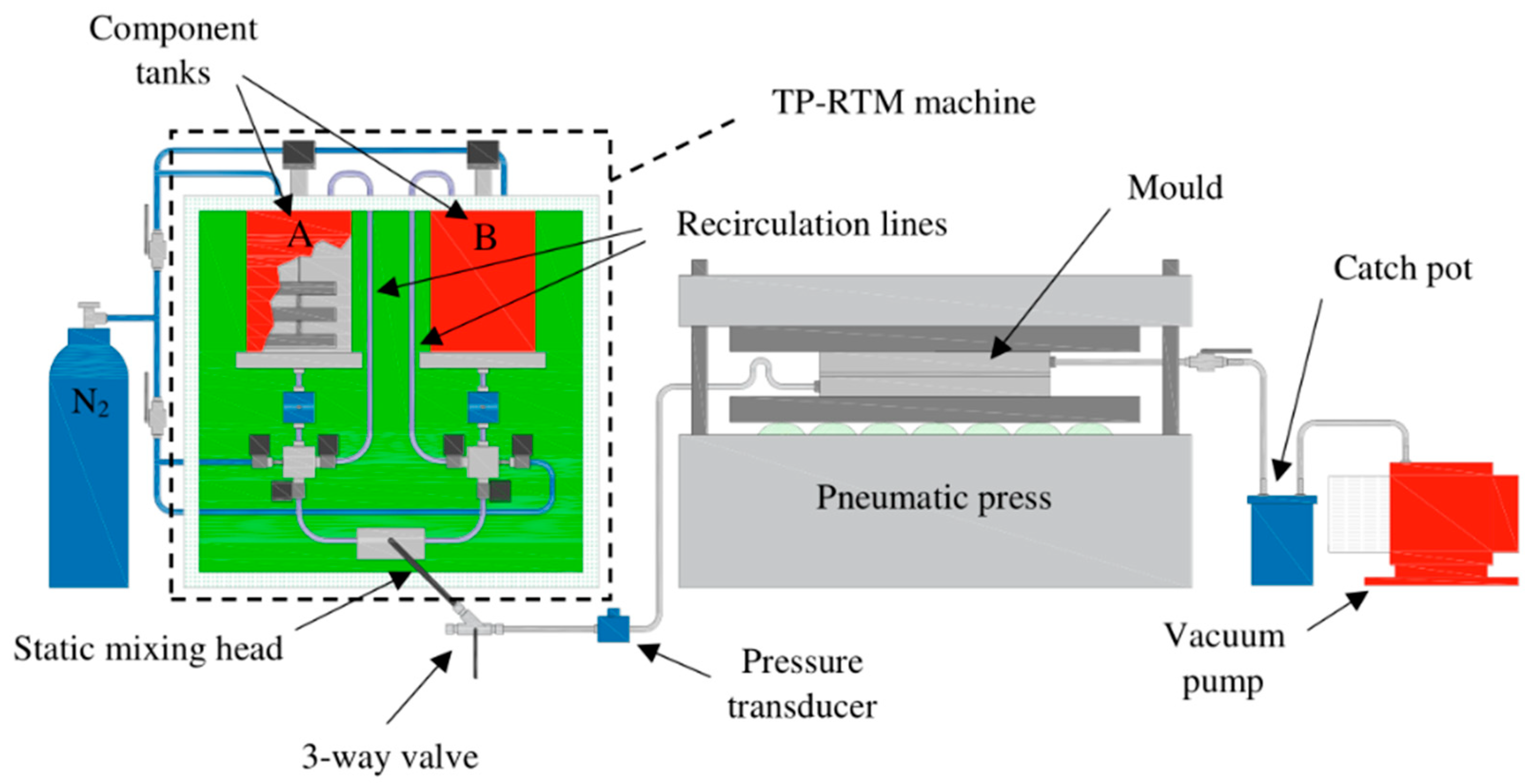
2.2. Laminate Manufacture

The ASTM D7136/D7136M test standard suggests layups for UD tape and woven fabric. Due to the fact that the glass fibre fabrics used in this study are UD, a [45°/0°/45°/90°]s layup like that suggested for UD tape was used with a cure ply thickness of 0.50 mm. The injection/mould setup used was the same as that developed by Murray et al. [10] as shown in Figure 1. A similar 350 mm × 390 mm mould cavity but with 4 mm thickness was used to accommodate the thicker specimens required for impact testing.
Prior to infusion, all mould surfaces were cleaned with acetone, and two layers of Frekote 55NC mould release agent were applied. All interconnecting tubes between the TP-RTM machine and mould were cleaned using hot water to dissolve any caprolactam residue from previous runs, followed by drying in an oven at 110 °C to eliminate moisture. Eight layers of fabric with different orientations were cut to size and placed in the mould cavity. The upper mould half was placed on top to close the mould, which was sealed with silicone rubber. The mould was placed into a pneumatic press with platens heated to 130 °C. A vacuum was applied to the mould outlet, and the inlet line was sealed such that the cavity acted like a vacuum oven to dry the fabric. These conditions were maintained for approximately 90 min to completely remove moisture from the fabric.
The TP-RTM machine was set up as shown in Figure 1, with the A and B tanks as well as the enclosure temperature set to 90 °C. A flush run of the machine was carried out using pure ε-caprolactam to purge any residue left from previous runs. This was followed by purging the circulatory elements of the machine with nitrogen to replace air and create an inert environment. The precursor materials were then added to the individual component tanks with stirrers. This consisted of 98.2 mol% ε-caprolactam, divided between the two tanks, with 0.6 mol% bi-functional activator in Tank A, and 1.2 mol% catalyst in Tank B. The platen temperature of the press was increased to 160 °C prior to infusion with enough time for the mould to reach temperature. The individual components were recirculated and then injected, passing through a static mixing head to create a homogeneous mixture. The mixed resin was initially ejected through an outlet on the three-way valve to bleed any air/nitrogen ahead of the flow-front before entering the mould. The valve was then turned to direct the flow into the mould and infiltrate the fabric. Upon reaching the outlet, the outlet valve was slowly closed to build up a back pressure until a reading of approximately 4 bars was observed from the pressure transducer on the inlet side, at which point the inlet valve was also closed to seal the resin inside the mould. Polymerisation of the mixture (an exothermic reaction) then occurred in the presence of the fibres within minutes, creating a fully consolidated composite part within the mould. The heating was switched off, and when cool enough to handle, the mould was removed from the press and the laminate removed.

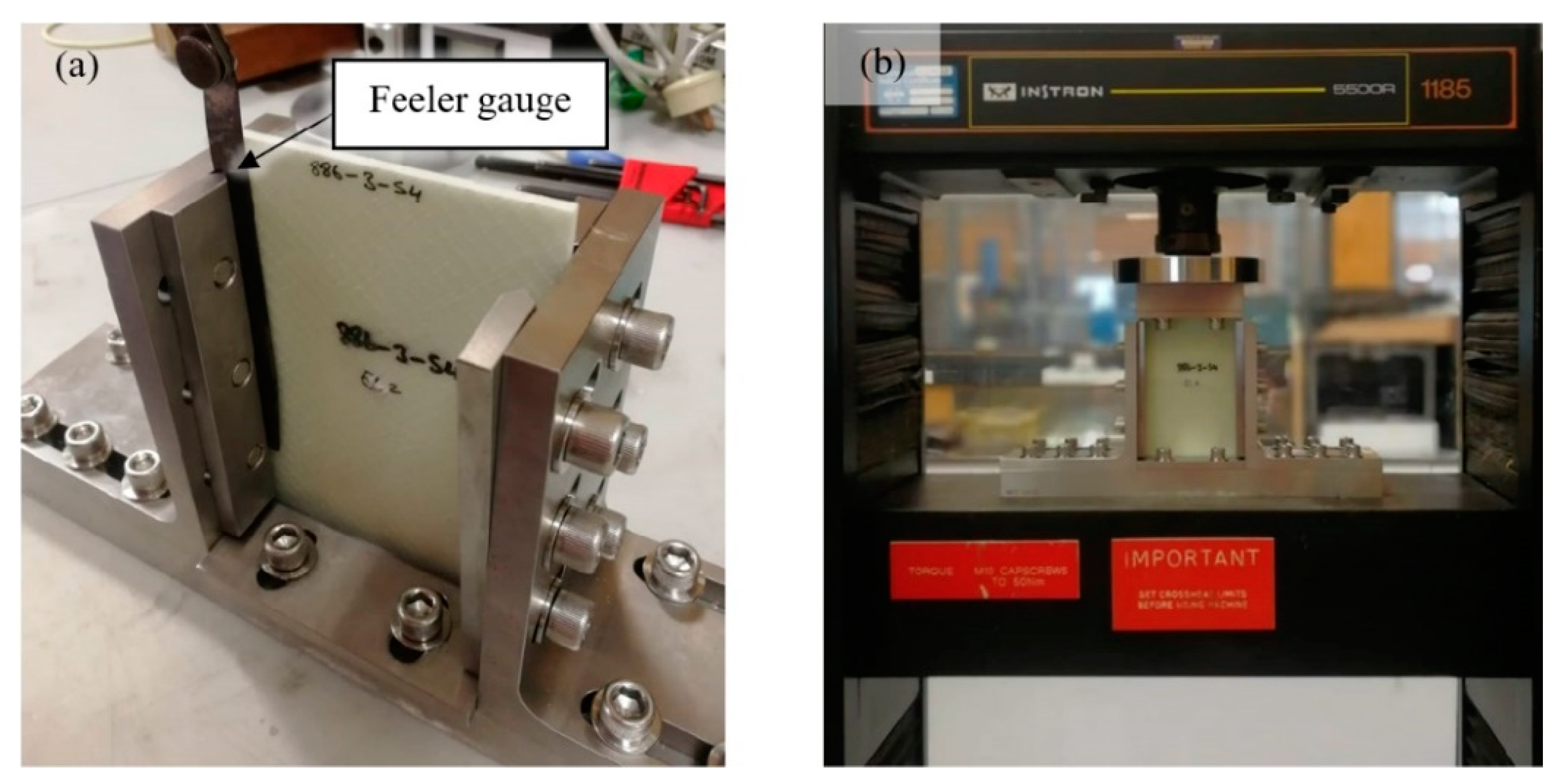
2.3. Sample Preparation

The impact specimens were extracted from six laminates with a very similar thickness (~3.8 mm), density (~1.9 g/cm3) and fibre volume fraction (~52%): three laminates with the 871 sizing and three with the 886 sizing. The samples were cut using a diamond blade cutting saw with coolant at a feed rate of ~300 mm/min. All samples were dried in an oven at 50 °C overnight and stored in a desiccator until testing.

2.4. Impact Testing

In order to measure the impact properties of the composite samples, an Imatek IM10-20 instrumented drop-weight impact test machine was used in accordance with ASTM-D7136, using 6″ × 4″ samples. Initial trial tests, which were carried out at various energy levels, showed that penetration of the GFRP occurred at ~60+ J, and so, 25 J and 50 J were chosen as the two sub-penetration energy levels with minimal visible damage, while 150 J was chosen as a safe value that would ensure full penetration of all specimens.
The initial impact velocity was measured with an instrumented laser detector immediately prior to impact and a 60 kN load cell mounted to the back of the striker was used to determine the impact force. A Phantom VEO 410 high-speed video camera was used to capture the impact on the lower surface of the specimens and was synchronised to the same software used to monitor impact force, from which the velocity and energy are calculated, such that the visual damage could be matched with these measurements at various time intervals.
The samples were held to the rigid stage of the test machine with four rubber-tipped toggle clamps. A 16 mm hemispherical striker and a total carriage mass of 9.756 kg were used in accordance with the test standard. The machine was fitted with an anti-rebound system which arrested the carriage after impact to prevent secondary impacts from occurring.

2.5. Post-Impact Damage Analysis

Ultrasound NDT was used initially to determine the post-impact damage area of specimens using 5 MHz and 2.4 MHz probes. However, due to the voids at the fibre-stitch intersections [10], combined with the large number of plies (eight in total) and their orientations, it was difficult to locate a consistent back wall to reflect the signal, and hence, determine the location of damage precisely. GF/APA-6 samples with the same number of plies, thickness and process conditions but manufactured using a UD layup did not experience the same issue, presenting a relatively consistent back wall.
Due to the partial translucency of the glass fibre/APA-6 composite, a high-intensity white light was used to observe the damage area. A camera was used to capture this damage on both the upper and lower sides of the specimens. The images were then edited using ImageJ so that the damage area could be isolated for thresholding and analysis. The damage area was then defined as a percentage of the total specimen area. For the penetrated specimens tested at 150 J, additional side shots were taken to capture the out-of-plane damage.
A number of impacted samples were cut across the damaged area to observe cross-sections so that failure mechanisms could be determined. A JEOL JSM-6010PLUS/LV Scanning Electron Microscope (SEM) was used to observe samples using an accelerating voltage of 15 kV.

2.6. Compression-After-Impact

Compression after impact (CAI) tests were carried out on specimen’s impacted at all three energy levels and were compared with un-impacted specimens. The tests were carried out in accordance with ASTM D7137/D7137M using a specific compressive residual strength support fixture for the test as shown in Figure 2a. The thickness, width and length dimensions of each sample were measured using a micrometre and Vernier callipers prior to placement in the fixture. The fixture consisted of adjustable retention plates to prevent buckling of the specimens. A feeler gauge was used to ensure a consistent gap of 0.05 mm between the samples and the retention plates was maintained. The upper piece of the fixture was placed on top of the sample, and the assembled setup was placed between a set of flat, horizontal and parallel platens in an Instron 1185 universal test machine as shown in Figure 2b.

3. Results and Discussion

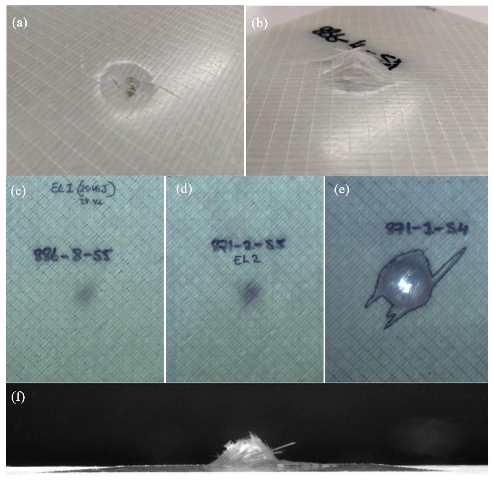
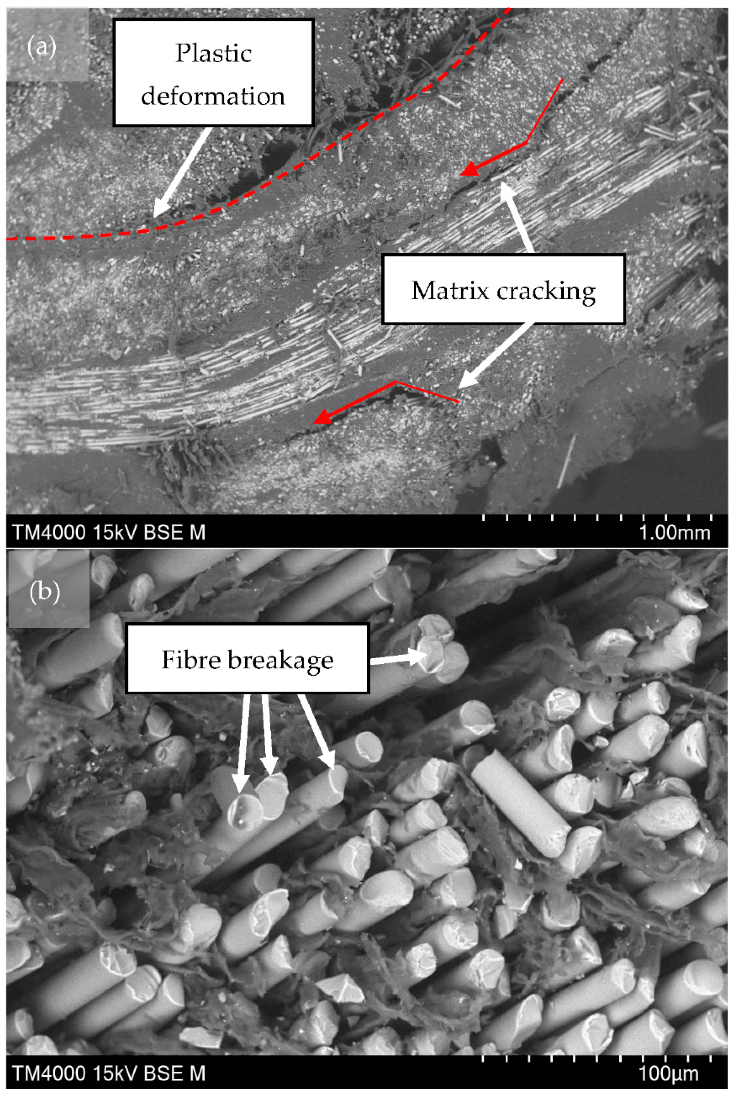
3.1. Damage Analysis
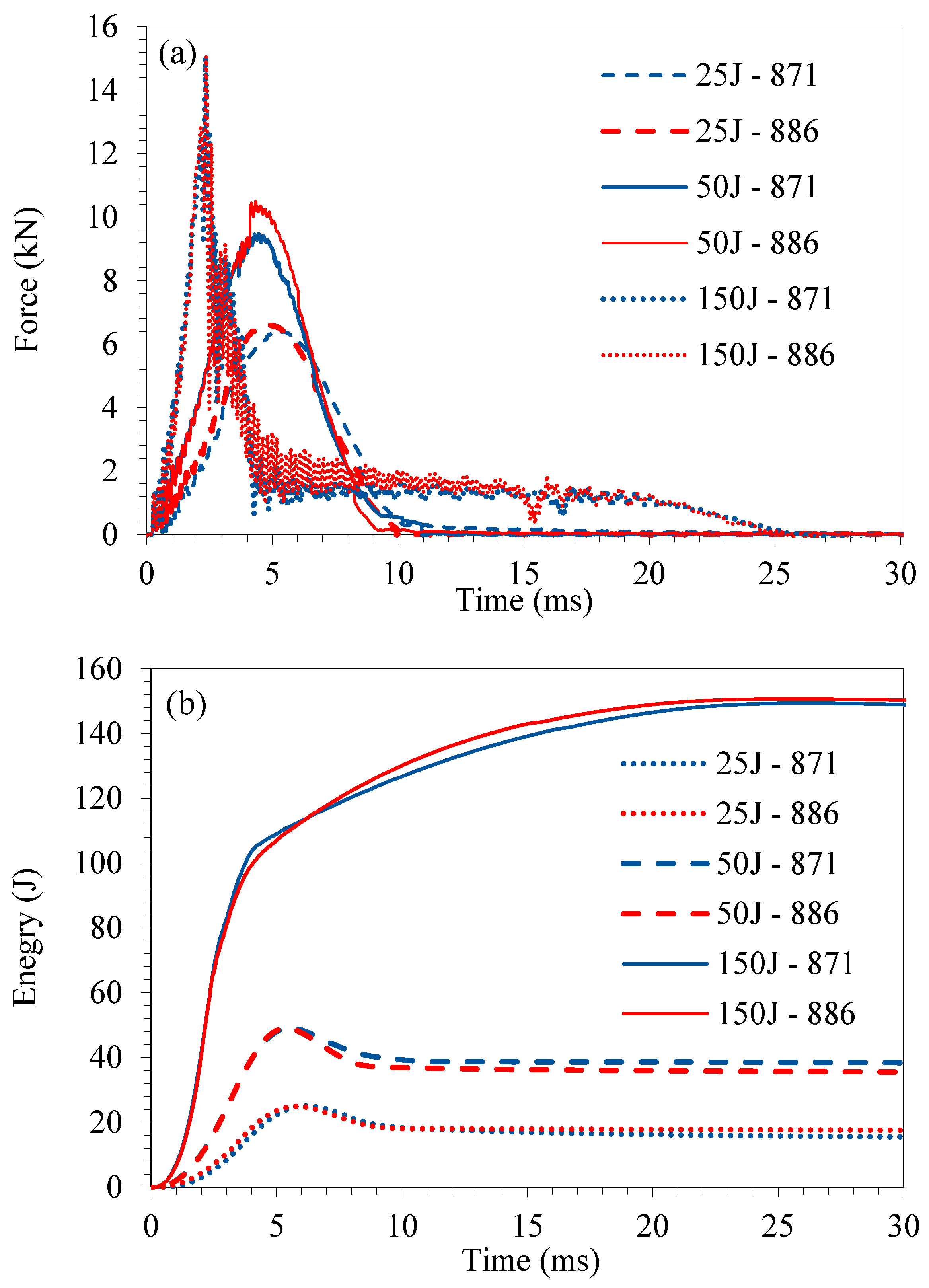
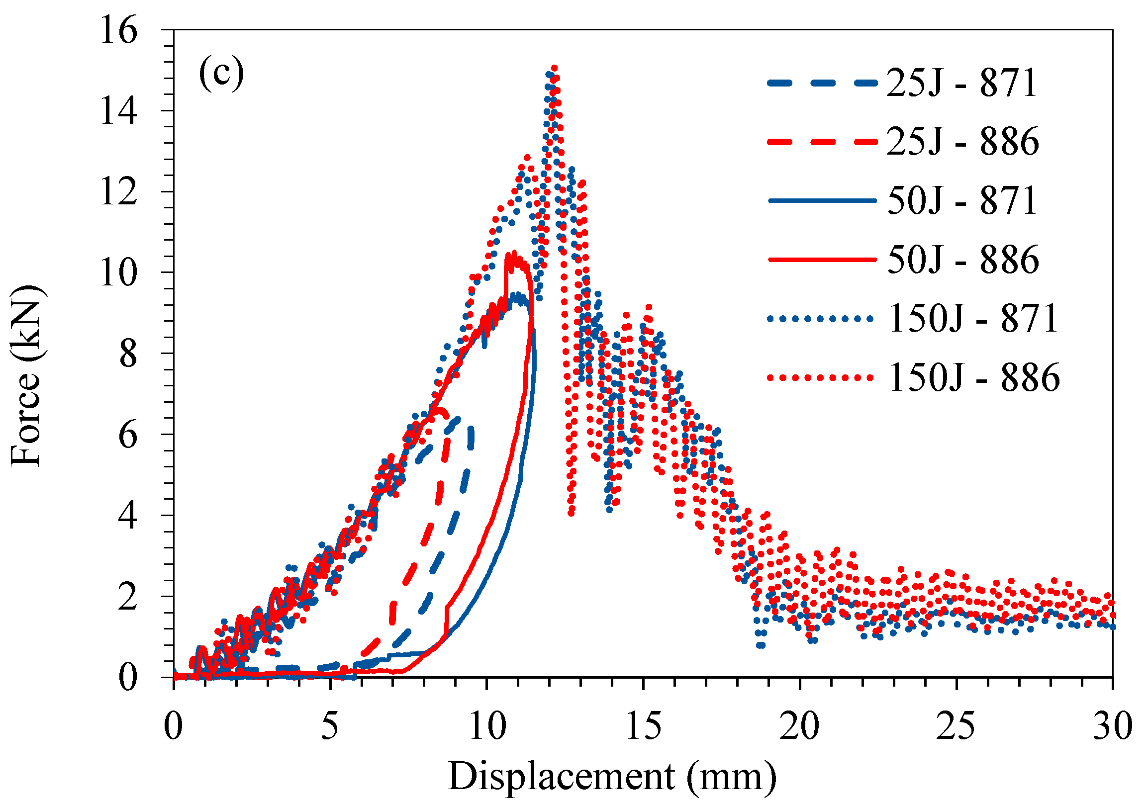
Photographs of the damaged glass–fibre/APA-6 composites manufactured using both different sizings are shown in Figure 3. From visual inspection, it was clear that the damage incurred by the composites at 25 J and 50 J was not significant and was localised to the area immediately around the contact point with the striker. While the samples tested at 150 J experienced full penetration, the damage was very localised. Due to the plastic behaviour of the APA-6 matrix, significant amounts of energy were absorbed within the immediate area surrounding the striker. This prevented the spread of damage as seen in more brittle materials [11]. Damage area measurements are given in Table 3 for each impact energy/sizing case. These showed that below 50J, the amount of damage for both the 871 and 886 cases was similar, with clear but minimal plastic deformation around the area of impact. Fully penetrated samples showed much more severe damage, with the 871 composite exhibiting a 23% larger damage area on average, compared to the 886 composite. This is likely due to a higher degree of delamination occurring in the 871 case due to poorer interfacial bonding.
SEM of cross-sectioned samples in the damaged region demonstrated that there are three main failure mechanisms observed (see Figure 4). The dominant type of failure was plastic deformation, indicated by the curvature of the fibres without fracture in the matrix, as shown in Figure 4a. This was expected for this material, which was shown by Murray et al. [10] to exhibit large plastic deformations in the unreinforced polymer and in loading transverse to the fibres of the composite. It is clear that a large degree of matrix cracking also occurred. From observation of areas closer to the impact area (to the right in Figure 4a), initial matrix cracking occurred within bundles but showed bias during propagation along interlaminar pathways. Figure 4b demonstrates full-fibre breakage in areas immediately surrounding the centre point of contact with the striker. While matrix cracking and fibre breakage are very common in thermoset composites, plastic deformation is not, which makes this type of failure interesting, considering that the part is manufactured using resin transfer moulding.

3.2. Impact Data

In terms of energy absorption and maximum force experienced during impact, there was no clear difference between the two sizing types up to the point of failure (see Figure 5). The peak energy was 64.2 ± 3.7 J for the 871 and 63.3 ± 8.1 J for the 886 RXN. While a similar amount of energy was absorbed by both, the method of failure was slightly different, which was observed from visual inspection. The sudden jump in force in Figure 5a for the 886 case at 50 J was a random feature from this specific sample, and was not a common occurrence across the sample set. The peak loads induced on samples for each case was similar for both sub-penetration and fully penetrated samples. This indicates that were the materials to be used in an automotive application, the deceleration forces experienced by the passenger would be similar if manufactured from either sizing type. The measured damaged area in 871 samples tested at 150 J was approximately 23% higher than that for the 886 RXN case on average. Due to improved interfacial adhesion, the 886 RXN material was less likely to suffer delamination to the same degree as the 871, and as a result, the measured damage area on the surface was less.

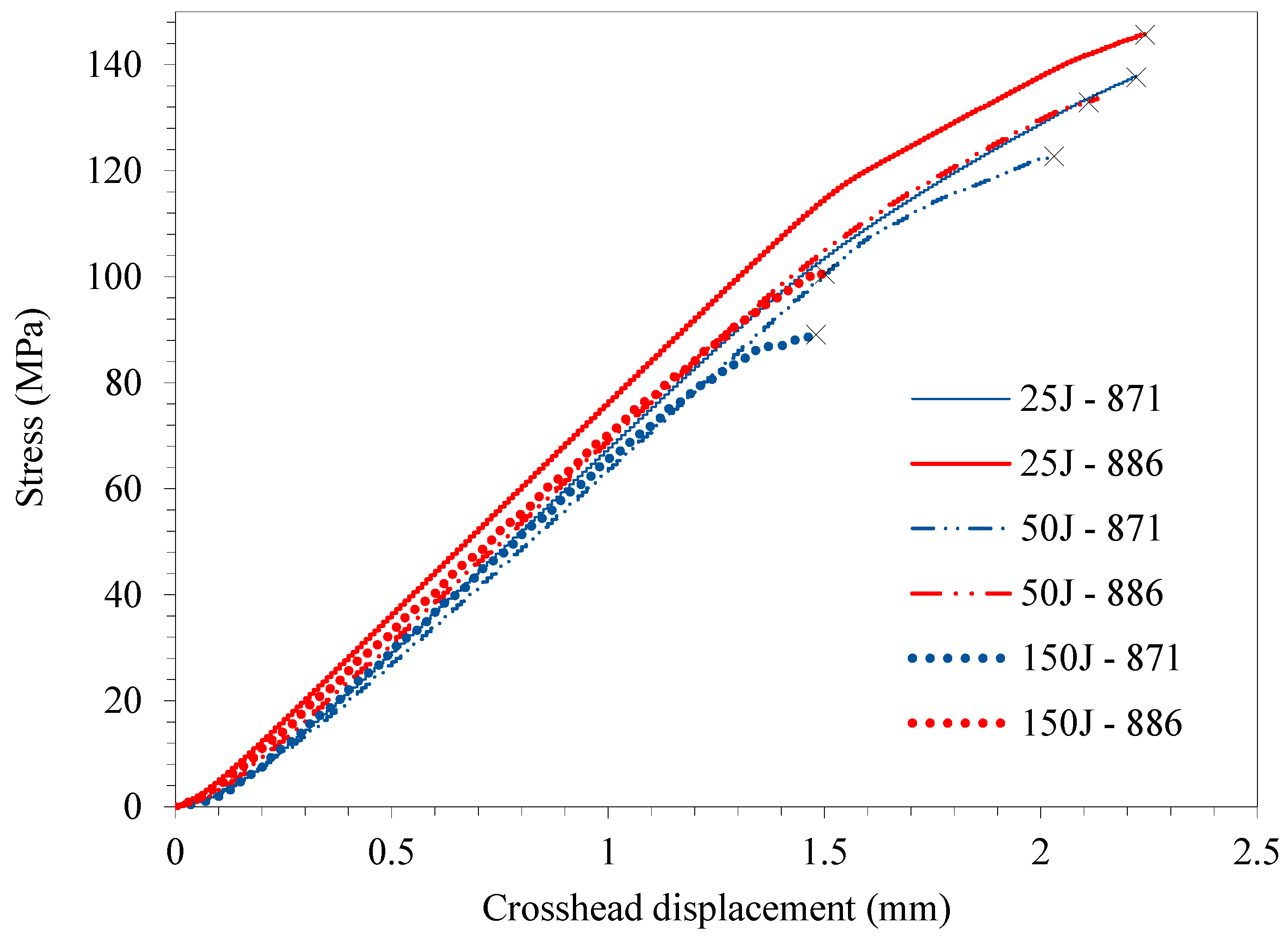
3.3. Compression-after-Impact

The compression-after-impact results for specimens tested at three different energy levels for the 871 and 886 RXN cases are presented in Figure 6 and Table 3. Due to the low amount of damage caused to the specimens at 25 J and 50 J, its effect on the compressive properties was barely noticeable, and for the 25 J samples, the average impact strength of the impacted specimens was higher than that of the unimpacted specimens. The scatter is relatively large for the strength values, making it almost impossible to make any clear conclusions about differences between the 871 and 886 RXN cases. It is clear, however, that the penetration of the specimens at 150 J for both cases caused a reduction in strength of 29 ± 8% of the unimpacted strength.

3.4. Overall Discussion of Results

Study of the response of the 871 and 886 RXN glass fibre composites to impact showed that there was very little difference between their performances. At sub-penetration energy levels, the average 871 composite performed slightly better than the 886 RXN in terms of energy absorbed per unit force, however, with limited statistical significance (p-value of 0.06 at 25 J and 0.24 at 50 J). The opposite was true for average values of penetrated specimens but once again, the difference was insignificant, with a high p-value of 0.16. There was noticeably more surface damage in the 871 case in the form of delaminations, however, the extent of through-thickness damage is not known as the light method used only detects in-plane damage area distribution without discriminating distribution through the thickness. Both sizings performed similarly in compression-after-impact tests, proving that the increased amount of damage observed on the surface of the 871 did not have profound effects on the mechanical performance.
Overall, it should be noted that this study proved how well the thermoplastic composites perform in out-of-plane impact scenarios. The material’s ability to limit damage spread from the area of contact with the striker means that a structure can retain a large fraction of its bulk properties after impact. It was shown that these materials can be locally damaged, through plastic deformation, at the point of impact and yet still carry similar loads to undamaged specimens. In contrast, most thermoset composites are brittle and once they are damaged, their mechanical performance is severely compromised [11].
Even though the 886 RXN composite was shown to have superior Mode I fracture performance in a previous study [12], this had little effect on either the impact performance or post-impact performance [29]. This observation matches with studies in the literature which state that Mode I fracture toughness, as measured by DCB testing, has little effect on the damage caused by impact or compression after impact [30]. On the other hand, the Mode II fracture toughness measured using end-notch testing has been shown to have a direct correlation with impact damage, which indirectly affects the compression-after-impact performance.
The method used for determining damage in the composites was somewhat unconventional. Ideally, ultrasound would have been used; however, there were issues with using this method, due to the difficulty in finding a back wall to reflect the waves. This is a common NDT problem in composites reinforced with glass-fibre fabrics, which reflect the ultrasound signal and prevent it from reaching the back wall.
When considering the context of this work with respect to the material’s use in automotive applications, the primary aim is to produce parts that will absorb as much energy as possible while minimising the force induced. Secondary to this is the ability of the material to limit the overall part damage and to maintain structural integrity. In terms of safety, these parts can be sacrificial in order to protect the passenger; however, parts that can meet the primary requirements and also maintain structural integrity have an added bonus. Due to the very specific nature of the layup and part geometry used, it would be possible to compare this material with a thermoset composite material without using the exact same conditions. A previous study carried out by the authors demonstrated such a comparison; however, using carbon fibre (CF) fabric as the reinforcement [11]. This study compared the impact behaviour of CF/APA-6 to CF/epoxy using both the same fabric, layup and mould cavity. With such variables fixed, the comparison was a valid one. Results showed that the CF/APA-6 absorbed ~21% more energy prior to breaking, ~7% less force was induced, and one-third the amount of damage area caused. On all accounts, the APA-6 matrix outperformed the epoxy matrix; and therefore, it would be expected that similar observations would be observed were such a comparative study carried out using glass fibre as the reinforcement.

4. Conclusions

While the penetration surface area damage in the glass fibre composite using the standard silane sizing (871) was ~23% higher than that using the functionalised sizing (886 RXN), the overall energy absorbed, and peak impact force induced, was roughly the same. In both cases, 4 mm thick samples with a fibre volume fraction of ~52% absorbed 63–65 J of energy prior to failure, with induced peak impact loads of 14–15 kN. The high strain-to-failure of the APA-6 matrix allowed absorption of impact energy through plastic deformation. This confined damage to areas immediately around the point of impact and restricted travel of damage across the specimens, even where full penetration occurred. This behaviour is typical for tough polymers and proves the benefits of their use in composites.
Sub-penetration energy levels caused barely noticeable effects on compressive strength while the penetrated specimens had a failure load that was ~71% of the original unimpacted capacity for both the 871 and 886 RXN cases. The results indicate that improved interfacial adhesion between the fibres and matrix, in this case, has no noticeable effect on the impact performance within the range of samples tested, with the exception of damage.

Author Contributions

Conceptualization, J.J.M., S.B., K.G. and C.M.Ó.B.; data curation, J.J.M. and A.B.; formal analysis, J.J.M. and A.B.; funding acquisition, S.B., K.G. and C.M.Ó.B.; investigation, J.J.M.; methodology, J.J.M., T.A., S.B., A.B., K.G., E.D.M. and C.M.Ó.B.; project administration, J.J.M., T.A., S.B., A.B. and C.M.Ó.B.; resources, J.J.M., T.A., S.B. and C.M.Ó.B.; software, T.A.; supervision, T.A., S.B., K.G. and E.D.M.; validation, A.B., E.D.M. and C.M.Ó.B.; visualization, J.J.M.; writing—original draft, J.J.M., S.B. and C.M.Ó.B.; writing—review and editing, J.J.M., T.A., S.B., A.B., K.G., E.D.M. and C.M.Ó.B. All authors have read and agreed to the published version of the manuscript.

Funding

This research received funding from The University of Edinburgh, Johns Manville, the University of Auckland and the EPSRC Future Composites Manufacturing Research Hub.

Institutional Review Board Statement

Not applicable.

Acknowledgments

The authors would like to thank Johns Manville (Littleton, CO, USA) who have co-funded this work, supplied the fabrics used in the study and provided a lot of expert advice and knowledge; and the EPSRC Future Composites Manufacturing Research Hub, for funding part of the exchange at the University of Auckland through the International Exchange Fund. I would also like to thank Brüggemann GmbH & Co. KG (Heilbronn, Germany) for providing the caprolactam and all colleagues who supported this work including Edward Monteith, Evanthia Pappa, Andrea Tinone, Callum Turnbull, Stephen Cawley and Jos Geurts.

Conflicts of Interest

The authors declare no conflict of interest.

References

  1. The Benefits & Advantages of Plastic. Available online: https://www.bpf.co.uk/industry/benefits_of_plastics.aspx (accessed on 29 June 2021).
  2. Biron, M. Thermoplastics and Thermoplastic Composites, 2nd ed.; Elsevier: Amsterdam, The Netherlands, 2012; ISBN 9781455778980. [Google Scholar]
  3. Rijswijk, K.; Van Bersee, H. Thermoplastic Composite Wind Turbine Blades; TU Delft: Delft, The Netherlands, 2007. [Google Scholar]
  4. Khan, L.A.; Mehmood, A.H. Cost-Effective Composites Manufacturing Processes for Automotive Applications. In Lightweight Composite Structures in Transport: Design, Manufacturing, Analysis and Performance; Woodhead Publishing: Sawson, UK, 2016; pp. 93–119. ISBN 9781782423430. [Google Scholar]
  5. European Parliament. Council of the European Union REGULATION (EU) No 333/2014 OF THE EUROPEAN PARLIAMENT AND OF THE COUNCIL of 11 March 2014 amending Regulation (EC) No 443/2009 to define the modalities for reaching the 2020 target to reduce CO2 emissions from new passenger cars. Off. J. Eur. Union L 103/15 2014. [Google Scholar]
  6. BMW Group Press Club. Press Release; BMW Group PressClub: Richnmond Hill, ON, Canada, 2016. [Google Scholar]
  7. Ishikawa, T.; Amaoka, K.; Masubuchi, Y.; Yamamoto, T.; Yamanaka, A.; Arai, M.; Takahashi, J. Overview of automotive structural composites technology developments in Japan. Compos. Sci. Technol. 2018, 155, 221–246. [Google Scholar] [CrossRef]
  8. Jacob, G.C.; Fellers, J.F.; Starbuck, J.M.; Simunovic, S. Crashworthiness of automotive composite material systems. J. Appl. Polym. Sci. 2004, 92, 3218–3225. [Google Scholar] [CrossRef]
  9. Farley, G.L. Effect of Fiber and Matrix Maximum Strain on the Energy Absorption of Composite Materials. J. Compos. Mater. 1986, 20, 322–334. [Google Scholar] [CrossRef]
  10. Murray, J.J.; Robert, C.; Gleich, K.; McCarthy, E.D.; Ó Brádaigh, C.M. Manufacturing of unidirectional stitched glass fabric reinforced polyamide 6 by thermoplastic resin transfer moulding. Mater. Des. 2020, 189, 108512. [Google Scholar] [CrossRef]
  11. Murray, J.J.; Allen, T.; Bickerton, S.; Gleich, K.; McCarthy, E.D.; Ó Brádaigh, C.M. Impact Performance of Thermoplastic Resin Transfer Moulded Carbon Fibre Composites. In Proceedings of the SAMPE Europe Conference, Amsterdam, The Netherlands, 30 September–1 October 2020; pp. 3–12. [Google Scholar]
  12. Murray, J.J.; Gleich, K.; McCarthy, E.D.; Ó Brádaigh, C.M. Properties of polyamide-6 composites using a low-cost thermoplastic resin transfer moulding system. In Proceedings of the ICCM International Conferences on Composite Materials, Melbourne, Australia, 11–16 August 2019. [Google Scholar]
  13. Boros, R.; Sibikin, I.; Ageyeva, T.; Kovács, J.G. Development and validation of a test mold for thermoplastic resin transfer molding of reactive PA-6. Polymers 2020, 12, 976. [Google Scholar] [CrossRef] [PubMed]
  14. van Rijswijk, K.; Bersee, H.E.N. Reactive processing of textile fiber-reinforced thermoplastic composites-An overview. Compos. Part A Appl. Sci. Manuf. 2007, 38, 666–681. [Google Scholar] [CrossRef]
  15. van Rijswijk, K.; van Geenen, A.; Bersee, H.E.N. Textile fiber-reinforced anionic polyamide-6 composites. Part II: Investigation on interfacial bond formation by short beam shear test. Compos. Part A Appl. Sci. Manuf. 2009, 40, 1033–1043. [Google Scholar] [CrossRef]
  16. van Rijswijk, K.; Bersee, H.E.N.; Jager, W.F.; Picken, S.J. Optimisation of anionic polyamide-6 for vacuum infusion of thermoplastic composites: Choice of activator and initiator. Compos. Part A 2006, 37, 949–956. [Google Scholar] [CrossRef]
  17. van Rijswijk, K.; Lindstedt, S.; Bersee, H.E.N.; Gleich, K.F.; Titzschkau, K.; McDade, E.J. Reactively processed polyamide-6 structural composites for automotive applications. In Proceedings of the 6th Annual SPE Automotive Composites Conference, Troy, MI, USA, 12–14 September 2006. [Google Scholar]
  18. van Rijswijk, K.; Teuwen, J.J.E.; Bersee, H.E.N.; Beukers, A. Textile fiber-reinforced anionic polyamide-6 composites. Part I: The vacuum infusion process. Compos. Part A Appl. Sci. Manuf. 2009, 40, 1–10. [Google Scholar] [CrossRef]
  19. Osváth, Z.; Sz, A.; Pásztor, S.; Szarka, G.; Balázs, Z.L.; Iván, B. Post-Polymerization Heat Effect in the Production of Polyamide 6 by Bulk Quasiliving Anionic Ring-Opening Polymerization of ε-Caprolactam with Industrial Components: A Green Processing Technique. Processes 2020, 8, 856. [Google Scholar] [CrossRef]
  20. Yan, C.; Li, H.; Zhang, X.; Zhu, Y.; Fan, X.; Yu, L. Preparation and properties of continuous glass fiber reinforced anionic polyamide-6 thermoplastic composites. Mater. Des. 2013, 46, 688–695. [Google Scholar] [CrossRef]
  21. Gomez, C.; Salvatori, D.; Caglar, B.; Trigueira, R.; Orange, G.; Michaud, V. Resin Transfer molding of High-Fluidity Polyamide-6 with modified Glass-Fabric preforms. Compos. Part A Appl. Sci. Manuf. 2021, 147, 106448. [Google Scholar] [CrossRef]
  22. Kohan, M.I. Nylon Plastics Handbook; Hanser Pub Inc: Munich, Germany, 1995; ISBN 9783446170483. [Google Scholar]
  23. AP-NYLON® Additives. Available online: https://www.brueggemann.com/en/ap-nylon-additives (accessed on 16 May 2021).
  24. Bessell, T.J.; Hull, D.; Shortall, J.B. The effect of polymerization conditions and crystallinity on the mechanical properties and fracture of spherulitic nylon 6. J. Mater. Sci. 1975, 10, 1127–1136. [Google Scholar] [CrossRef]
  25. Jogur, G.; Nawaz, K.A.; Das, A.; Mahajan, P.; Alagirusamy, R. Impact properties of thermoplastic composites. Text. Prog. 2018, 50, 109–183. [Google Scholar] [CrossRef]
  26. Barkoula, N.M.; Alcock, B.; Cabrera, N.O.; Peijs, T. Flame-Retardancy Properties of Intumescent Ammonium Poly (Phosphate) and Mineral Filler Magnesium Hydroxide in Combination with Graphene. Polym. Polym. Compos. 2008, 16, 101–113. [Google Scholar] [CrossRef]
  27. Vaidya, U.K.; Chawla, K.K. Processing of fibre reinforced thermoplastic composites. Int. Mater. Rev. 2008, 53, 185–218. [Google Scholar] [CrossRef]
  28. Obande, W.; Mamalis, D.; Ray, D.; Yang, L.; Ó Brádaigh, C.M. Mechanical and thermomechanical characterisation of vacuum-infused thermoplastic- and thermoset-based composites. Mater. Des. 2019, 175, 107828. [Google Scholar] [CrossRef]
  29. Murray, J.J. Thermoplastic Resin Transfer Moulding of Tough Recyclable Composites for High Volume Manufacturing; The Univeristy of Edinburgh: Edinburgh, UK, 2020. [Google Scholar]
  30. Nettles, A.T.; Scharber, L. The Influence of GI and GII on the compression after impact strength of carbon fiber/epoxy laminates. J. Compos. Mater. 2018, 52, 991–1003. [Google Scholar] [CrossRef]
Figure 1. Assembled TP-RTM setup for polymer/composite manufacture [10].
Energies 14 05790 g001
Figure 2. (a) Loading of fixture used for compression-after-impact testing and (b) the fixture positioned between platens of test machine during testing of a GF/APA-6 sample.
Energies 14 05790 g002
Figure 3. Visual appearance of damage in GFRP specimens after impact testing at 150 J on (a) the upper side (b) the lower side; images taken normal to specimens tested at (c) 25 J, (d) 50 J, (e) 150 J; and (f) a side-view of a damaged 150 J specimen.
Energies 14 05790 g003
Figure 4. Representative SEM image of the damaged region in samples. The image clearly shows (a) matrix cracking and (b) fibre breakage. The large degree of plastic deformation is indicated by the curvature of the fibres in the composite without fracture in the polymer matrix.
Energies 14 05790 g004
Figure 5. Representative data recorded from impact tests carried out on GF/APA-6 from fibres using both the 871 and 886 RXN fibre sizings in terms of (a) force-time, (b) energy-time, and (c) force-displacement.
Energies 14 05790 g005aEnergies 14 05790 g005b
Figure 6. Examples of stress-displacement data from compression-after-impact testing of GF/APA-6 using 871 and 886 RXN sizings. Note that while the average values between the 25 J and 50 J energies are very similar, slightly more conservative data is presented for the 50 J in this figure so that the data does not visually overlap.
Energies 14 05790 g006
Table 1. APA-6 matrix precursor materials.
PrecursorProduct DescriptionBrand NameSupplier
Monomerε-caprolactamAP-NYLON® CaprolactamBrüggemann
CatalystSodium caprolactamateBRUGGOLEN® C10Brüggemann
ActivatorHexamethylene-1,6-dicarbamoylcaprolactamBRUGGOLEN® C20pBrüggemann
Table 2. Reinforcement material details, each supplied in a unidirectional non-crimp stitched fabric.
ReinforcementFabric ArchitectureFibre RovingsSupplier
871640 g/m2: 1 layer 0° GF (635 g/m2), PES warp stitch (5 g/m2)StarRov®871Johns Manville
886640 g/m2: 1 layer 0° GF (635 g/m2), PES warp stitch (5 g/m2)StarRov®886 RXNJohns Manville
Table 3. Summary of the data gathered from analysis and testing of GF/APA-6 material during and after impact. The compression-after-impact (CAI) data is given as a percentage of the unimpacted strength. Note that the damage area is reported as a fraction of the total specimen area.
Energy Level (J)SizingAverage Damage Area (%)Peak Energy
(J)
Peak Force
(kN)
Peak Energy/Force (J/kN)CAI (%)
25 J8711.2322.3 ± 0.86.5 ± 0.33.66 ± 0.18108 ± 6
886 RXN1.0722.8 ± 0.56.3 ± 0.43.45 ± 0.2597 ± 10
50 J 8711.3644.2 ± 2.59.1 ± 1.24.95 ± 0.9196 ± 7
886 RXN1.3445.2 ± 1.510.2 ± 1.14.47 ± 0.43100 ± 4
150 J8715.6964.2 ± 3.714.2 ± 1.24.54 ± 0.4371 ± 8
886 RXN4.6163.3 ± 8.114.8 ± 1.24.27 ± 0.2771 ± 8
Publisher’s Note: MDPI stays neutral with regard to jurisdictional claims in published maps and institutional affiliations.

