Article

Combining Dual Fluidized Bed and High-Temperature Gas-Cooled Reactor for Co-Producing Hydrogen and Synthetic Natural Gas by Biomass Gasification

Institute of Nuclear and New Energy Technology, Tsinghua University, Beijing 100084, China
*
Author to whom correspondence should be addressed.
Energies 2021, 14(18), 5683; https://doi.org/10.3390/en14185683
Submission received: 10 August 2021 / Revised: 6 September 2021 / Accepted: 6 September 2021 / Published: 9 September 2021
(This article belongs to the Special Issue Nuclear Integration and Thermal Energy Storage)

Abstract

:
Biomass gasification to produce burnable gas now attracts an increasing interest for production flexibility in the renewable energy system. However, the biomass gasification technology using dual fluidized bed which is most suitable for burnable gas production still encounters problems of low production efficiency and high production cost. Here, we proposed a large-scale biomass gasification system to combine dual fluidized bed and high-temperature gas-cooled reactor (HTR) for co-production of hydrogen and synthetic natural gas (SNG). The design of high-temperature gas-cooled reactor biomass gasification (HTR-BiGas) consists of one steam supply module to heat inlet steam of the gasifier by HTR and ten biomass gasification modules to co-produce 2000 MWth hydrogen and SNG by gasifying the unpretreated biomass. Software for calculating the mass and energy balances of biomass gasification was developed and validated by the experiment results on the Gothenburg biomass gasification plant. The preliminary economic evaluation showed that HTR-BiGas and the other two designs, electric auxiliary heating and increasing recirculated product gas, are economically comparative with present mainstream production techniques and the imported natural gas in China. HTR-BiGas is the best, with production costs of hydrogen and SNG around 1.6 $/kg and 0.43 $/Nm3, respectively. These designs mainly benefit from proper production efficiencies with low fuel-related costs. Compared with HTR-BiGas, electric auxiliary heating is hurt by the higher electric charge and the shortcoming of increasing recirculated product gas is its lower total production. Future works to improve the efficiency and economy of HTR-BiGas and to construct related facilities are introduced.

1. Introduction

Biomass gasification is a kind of environmentally friendly technology for various utilizations of biomass. Flexibility and efficiency in production are key characteristics for biomass gasification technologies, and therefore co-generation processes with a production of heat-and-power or heat-and-combustible gas are usually adopted to realize biomass gasification for practical industrial applications [1]. The co-generation process of heat and combustible gas, e.g., synthetic natural gas (SNG) and/or hydrogen, can provide flexible energy and material sources without increasing greenhouse gas emissions. Most of the present practical technologies utilize dual fluidized bed (DFB) including a steam gasifier and an air combustor which enables indirect gasification without diluting the produced combustible gas with the nitrogen in the combustion air [2,3,4].
Different demonstration projects based on the DFB concept have been constructed and operated to produce combustible gas. Several main designs are Gaya [5], fast internal circulating fluidized bed (FICFB) [6], Pyroneer [7], Alkmaar SNG [8] and Gothenburg biomass gasification (GoBiGas) [9]. The gasification plants still entail various significant issues that decrease the projects’ economic viability [10]. In 2018, the GoBiGas plant, the state-of-the-art SNG project that can produce up to 20 MWth of SNG, was mothballed due to economic reasons [11]. The main problem of GoBiGas is that the production efficiency will obviously decrease if using the normal biomass with a moisture content of up to 40% instead of the expensive pretreated wood pellets (moisture content of 8%) [12]. Higher moisture content will consume more heat and may change the gasification process and production. Another reason is its related small scale, 20 MWth of product gas, resulting in big heat loss [12] and high cost [11] in average production. If the unpretreated biomass with a moisture content of 40% can be used in a larger scale plant up to 200 MWth without the breakdown of its production efficiency, its economy may be greatly improved [13].
On the other hand, Chinese continuous economic development increases its energy consumption, attracting more attention to environmental and security issues regarding energy sources. In 2018, China imported 42.9% of the domestic consumption of natural gas and became the biggest importer of liquefied natural gas (LNG) in the world [14]. Much attention has been paid to the coal-based SNG industry by China, which is expected to be helpful for energy structure optimization, clean coal utilization and pollution reduction [15]. However, the coal-based SNG projects are widely criticized because of high carbon emissions, ambient environmental pollution, etc. [16]. In addition, China is also the world’s largest hydrogen producer whose main sources are coal and natural gas [17].
The abovementioned calls for a larger scale design for biogas production that applies to the unpretreated biomass by introducing a cheap high-temperature heat source with low carbon emissions. The 200 MWe high-temperature gas-cooled reactor pebble-bed module (HTR-PM) is designed by the Institute of Nuclear Energy and New Energy Technology (INET), Tsinghua University, China [18]. One high-temperature gas-cooled reactor (HTR) in the HTR-PM plant can provide 250 MWth super-heated steam up to around 570 °C with low carbon emissions.
Here, we propose a 200 MWth × 10 co-generation system, high-temperature gas-cooled reactor biomass gasification (HTR-BiGas), for producing hydrogen and SNG by integrating DFB and HTR. HTR-BiGas aims to improve the production efficiency and economy of biomass gasification by heating inlet steam of the gasifier with the high-temperature carbon-free steam from the HTR to cope with the unpretreated biomass with a moisture content of 40%. The HTR-BiGas plant consists of one HTR and ten biomass gasifiers based on the related designs in the HTR-PM plant and the GoBiGas plant, respectively. This paper compares HTR-BiGas and other related designs in terms of production efficiency and cost. Visual Basic. Net software was designed and developed to calculate the mass and energy balances in the biomass gasification process. Power of final product gas and various production efficiencies were compared for different designs, heating inlet steam by HTR, electric auxiliary heating and increasing recirculated product gas, on two scales (20 MWth and 200 MWth × 10), to gasify biomass with the moisture content of 8% or 40%. In addition, we conducted a preliminary economic analysis of the HTR-BiGas plant and the other two designs on the large scale of 200 MWth × 10. The paper ends with discussions of future works related to the HTR-BiGas project.

2. Materials and Methods

2.1. GoBiGas Plant

GoBiGas is a demonstration plant in Gothenburg, Sweden that was built to produce 20 MWth of SNG through biomass gasification [11]. Gothenburg Energy (Gothenburg, Sweden) owns the plant and Chalmers University of Technology is responsible for technical evaluation. The gasification section was constructed by Valmet AB (Stockholm, Sweden) on license from Repotec GmbH (Vienna, Austria) whose technology was originated from FICFB [6,19]. The construction of the GoBiGas plant started in 2011 and was completed in 2013. In 2018, it was mothballed due to economic reasons after achieving more than 1800 h of continuous operation and finally reaching 100% of the designed capacity.
The GoBiGas plant was part of the larger ambition to build biomass gasification plants in a commercial size (100 MWth or higher). The main technique advance of GoBiGas is optimized solid circulation using olivine as the main bed material and potassium carbonate (K2CO3, sometimes sulfur is added) as the additive which can increase the production efficiency and the gas quality [9,12].
Because the increase of the moisture content of the biomass will decrease the production efficiency, some efforts were investigated: high-temperature heating inlet steam and air, the introduction of electricity to the gasifier, increasing the ratio of recirculated product gas to the combustor and decreasing the heat losses of the DFB [12]. The related simulation investigation was conducted by using Aspen Plus by Aspentech (Bedford, Massachusetts, USA) to calculate the mass and energy balances of the DFB [20].
The improvement of the economy was also discussed by varying the biomass and the plant scale. If the normal unpretreated biomass, e.g., recovered wood, etc., can be adopted for the plant, the feedstock cost will be around one-fifth of that of the present GoBiGas plant [11,13]. Besides, the specific investment and operation costs of a 200 MWth plant will be around one-third of those of the GoBiGas plant [11,13]. A study compared several strategies for the production of intermediate burnable gas, SNG and/or hydrogen where scale-up designs (maximum as 80 MWth burnable gas) of the GoBiGas plant were proposed by using electricity (maximum 12.8 MW) as the auxiliary heat source [21].
The abovementioned discussions provide vital clues for us to propose a design for biomass gasification with higher efficiency and lower cost.

2.2. HTR-PM

The 200 MWe HTR-PM plant was designed by INET, Tsinghua University, China, which deploys two HTRs each with 250 MWth [18]. The construction of the HTR-PM plant started in 2008 in Rongchen, China, under the cooperation of China Huaneng Group (Beijing, China), China Nuclear Engineering and Construction (Beijing, China)and Tsinghua University. The HTR-PM plant is planned to connect to the grid at the end of 2021.
The HTR-PM plant has inherent safety that can be explained in three aspects: the use of the more heat-resistant and heat-substantial material, silicon carbide, as the fuel cladding; the lower volumetric power density of the reactor core; and the lower total power of the reactor [18]. Thus, the decay heat never heats the reactor core to the temperature limit. The following commercial plant whose design is the same as the HTR-PM plant will have an online electrovalence of around 0.093 $/kWh with a 9% annualized return in the expected lifetime of 30 years [22]. Besides, the steam generator (SG) of the plant can provide superheated steam up to around 570 °C. The temperature of the inlet steam of the gasifier in the GoBiGas plant is 345 °C [12]. Thus, the superheated steam can be used as a cheap low-carbon heat source to heat the inlet steam of the DFB for biomass gasification.

3. Results

3.1. Design of HTR-BiGas

The HTR-BiGas plant combines one HTR and ten DFBs for the co-generation of 2000 MWth hydrogen and SNG. The design of the HTR is the same as that in the HTR-PM plant and the design of the DFB is the scale-up of that in the GoBiGas plant which can co-produce 200 MWth hydrogen and SNG. The HTR provides 250 MWth superheated steam to heat the inlet steam of the ten DFBs through an intermediate heat exchanger (IHX). We integrate the water gas shift (WGS) reaction, the vacuum pressure swing adsorption (VPSA) process and the methanation process for the co-generation of hydrogen and SNG which are similar to those proposed in the previous studies [21,23].
As shown in Figure 1, the HTR-BiGas plant consists of one steam supply module and ten biomass gasification modules. The main parameters of GoBiGas and HTR-BiGas are compared in Table 1.
The steam supply module is composed of an HTR, an SG and three heat exchangers. The water in the SG is heated by the hot helium from the HTR core and becomes superheated steam to heat the feedwater in the IHX. The other two heat exchangers heat the feedwater using the flue gas from the combustors.
A biomass gasification module consists of a DFB unit and a gas co-generation unit. The HTR-BiGas plant has ten DFB units and ten gas co-generation units.
A DFB unit mainly includes a gasifier and a combustor to produce the product gas for the gas co-generation unit. The biomass is fed into the gasifier through the fuel feeder and reacts with the high-temperature steam from the steam supply module and the high-temperature oxygen in the fluidized bed materials from the combustor. The main raw gas is generated through a series of reactions such as pyrolysis, gasification and conversion, and a small amount of unreacted char is transported to the combustor through the fluidized bed materials. In the combustor, various combustion reactions occur between the high-temperature air and the substances, including char from the gasifier, recirculated gas from the scrubber, particles, rapeseed oil methyl (RME) and tar, benzene, toluene and xylene (BTX), etc. Some of the heat generated by the combustion is supplied to the gasifier through the bed materials, and the oxygen is also transported in the form of metal oxide. The raw gas generated from the gasifier is purified to remove particles, BTX, tar, etc., and sent to the gas co-generation unit. The RME is used to crystallize the tar to avoid saturation. The particles from the raw gas and a small amount of the product gas are sent to the combustor to provide additional heat to the DFB.
In the gas co-production unit, the unsaturated hydrocarbons in the product gas are converted into alkanes by an olefins hydrogenator and then flow through a COS hydrolyzer, an H2S scrubber and a guard bed in turn to remove sulfur compounds. Here, a balanced method is adopted for the co-generation of hydrogen and SNG with one VPSA process so that the volume ratio of hydrogen and carbon monoxide is controlled at around 47:1 by the WGS reactor. A separator is used to remove the carbon dioxide in the product gas to ensure the high efficiency of hydrogen separation. The hydrogen is separated through the VPSA process whose efficiency is around 90%. The remaining product gas in which the volume ratio of hydrogen and carbon is around 4.7:1 is delivered to a methanator for methanation to produce SNG.

3.2. Calculation Cases

Because the increase of the moisture content of the biomass will significantly decrease the production efficiency, some efforts were investigated in the GoBiGas plant: electric auxiliary heating, increasing recirculated product gas, high-temperature heating inlet air and steam and decreasing heat losses of the DFB [12,20]. Some techniques and economy evaluations were also carried out on the scale-up (200 MWth of product gas) of the GoBiGas plant [11,13]. These studies indicated that the co-generation systems often have higher production efficiencies than the systems only producing SNG. In addition, the scale-up of the biomass gasification plant can significantly improve its economy [13,21].
Here, we mainly discuss the co-generation designs for producing hydrogen and SNG at two kinds of scale in terms of the power of the final product gas, 20 MWth and 200 MWth × 10 using the unpretreated biomass with a moisture content of 40%. For each scale, 20 MWth or 200 MWth × 10, three designs are discussed by using different countermeasures: electric auxiliary heating, increasing recirculated product gas and heating inlet steam by HTR. HTR-BiGas is the large-scale design (200 MWth × 10) to heat inlet steam by HTR. The other two designs, electric auxiliary heating and increasing recirculated product gas, do not have an independent steam supply module and their biomass gasification modules are the same as those of HTR-BiGas. The steam supply components of these two designs are the same as those of the GoBiGas which uses the recovered heat from the flue gas [12].
We consider an additional co-generation case using the pretreated wood pellets with a moisture content of 8% to compare the calculation results of its mass and energy balances with those of the GoBiGas plant in the previous study [12].

3.3. Calculation Methodologies

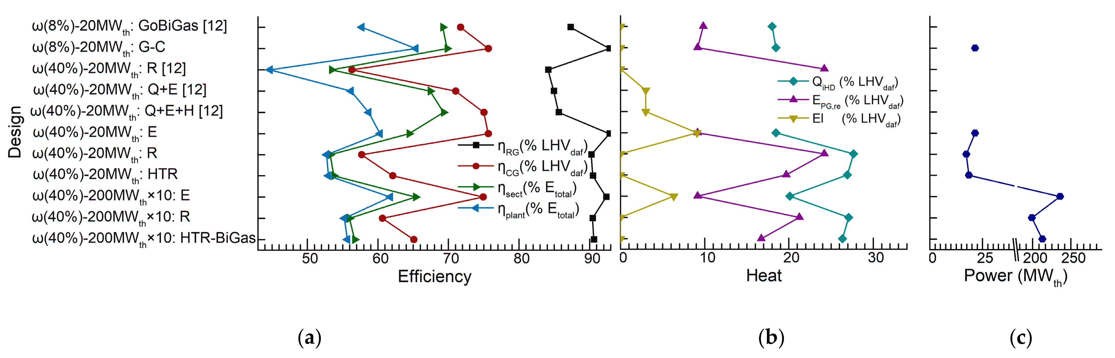
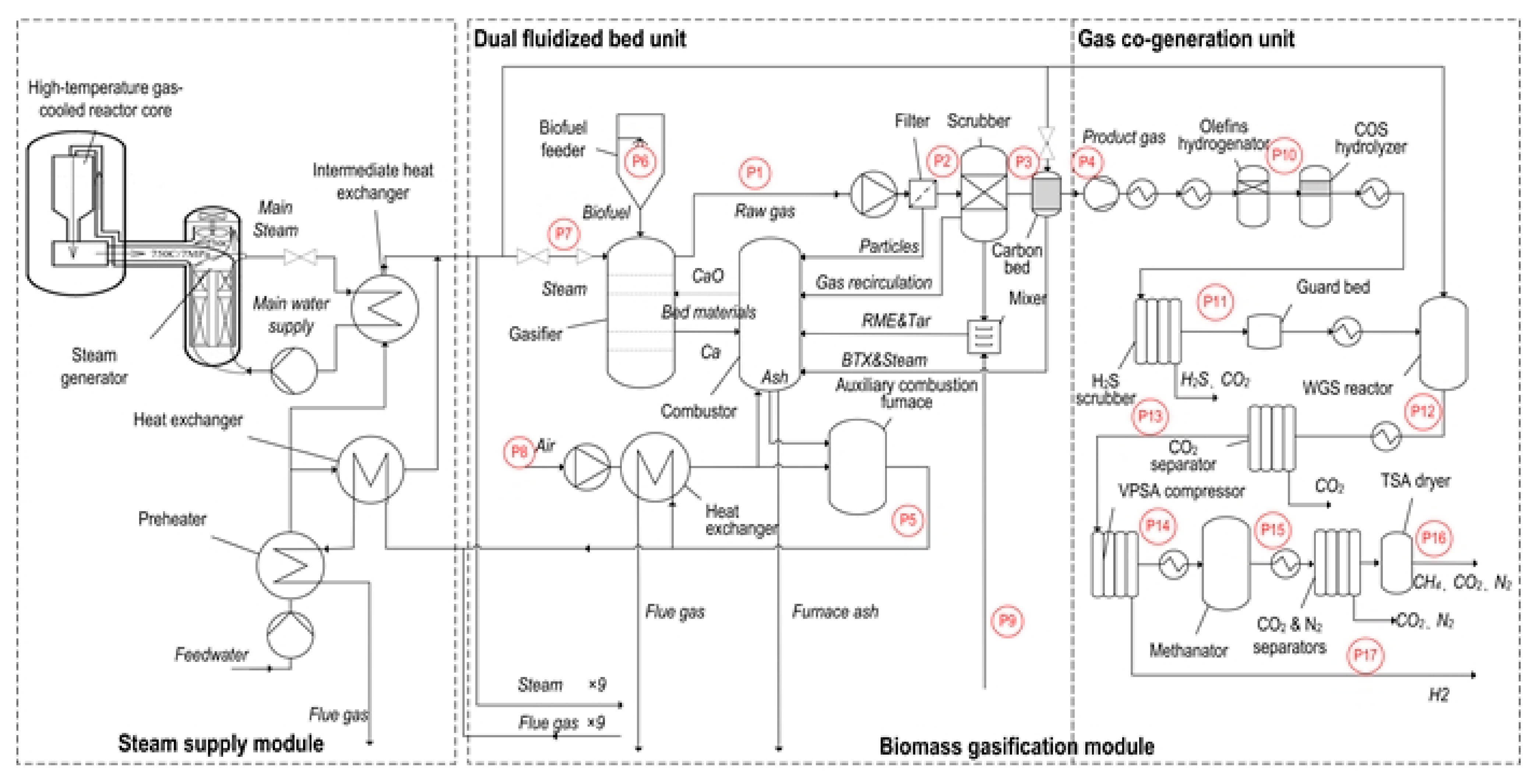
The HTR-BiGas consists of a steam supply module and ten biomass gasification modules, each of which includes a DFB unit and a gas co-generation unit. The mass and energy balances of the steam supply module are simple. The energy consumed in the gas co-generation unit is usually much less than that consumed by the DFB unit. In addition, HTR-BiGas has a conservative design that delivers around 25% output steam of the steam supply module to heat the various processes in the gas co-generation unit. The mass balance of the gas co-generation unit is also a simple process based on the mature techniques for producing hydrogen and SNG. Here, we only introduce the mass and heat balances of the DFB unit.

3.3.1. Basic Hypotheses and Configurations

We conducted the calculation of the mass and energy balances of the DFB based on the related methodologies for the GoBiGas plant [12,20]. The mass balance of the DFB is usually simplified to carbon, hydrogen and oxygen because other elements and substances, e.g., nitrogen, sulfur, ash, etc., have a negligible effect on the mass and energy balances [20]. The mass and energy balances are calculated on a dry ash-free (daf) basis [24]. In addition, some basic hypotheses are assumed as follows so the basic configurations for calculating the mass and energy balances of HTR-GoBiGas and other designs can be derived from those of the GoBiGas plant:
  • The components of the raw gas and the product gas from the DFB are only determined by the temperatures of the gasifier and the combustor and the bed materials transported between the gasifier and the combustor.
  • The flows of the raw gas and the product gas from the DFB are proportional to the input biomass if the ratio of the inlet steam to the inlet biomass on the daf basis is not changed.
  • Various items in the energy balance are independent of the scale of the biomass gasification plant except for the heat losses of the DFB to the ambiance.
  • The ratio of increased transported heat by bed materials to increased recirculated product gas is a constant value when the fraction of the recirculated product gas is higher than that of the GoBiGas plant.
The pieces of literature providing the physical and chemical properties of related substances are listed in Table 2, which makes the most of the studies related to the GoBiGas plant. When calculating the enthalpies of tar and BTX, tar and BTX are considered as different mixtures of toluene and naphthalene.

3.3.2. Mass Balance of DFB

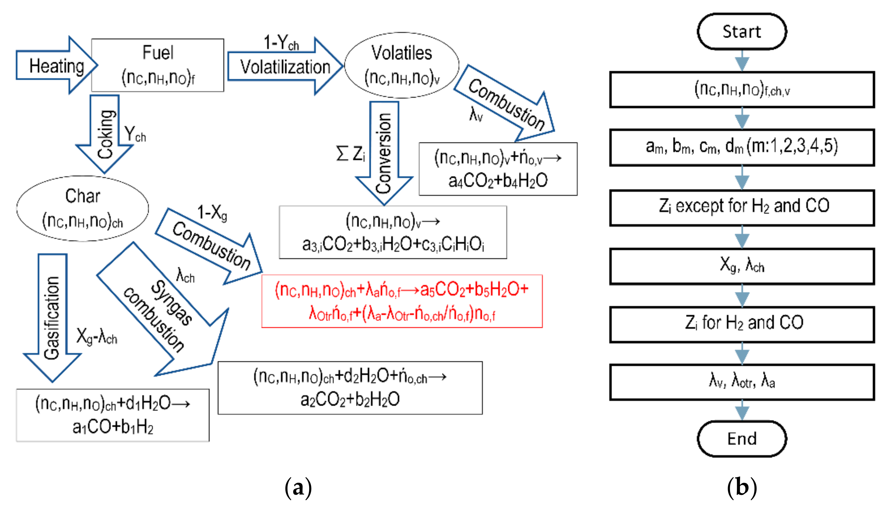
The pyrolysis process and chemical reactions of biomass gasification in the DFB are shown in Figure 2a based on the related studies for the GoBiGas plant [12,20]. The biomass in the gasifier is first converted into a little char and most of the volatiles. Then, various chemical reactions occur among char, volatiles, oxygen and steam, including char gasification, syngas combustion, volatiles conversion, volatiles combustion and char combustion. Y c h is the yield of char. The char fraction λ c h is gasified and oxidized. X g λ c h is the fraction of the gasified char which is converted to carbon monoxide and hydrogen. The remaining char ( 1 X g ) is transported to the combustor and then combusted. The volatiles produces most of the product gas through the conversion reaction. The remaining volatiles ( λ v ) combust with the oxygen transported from the combustor.
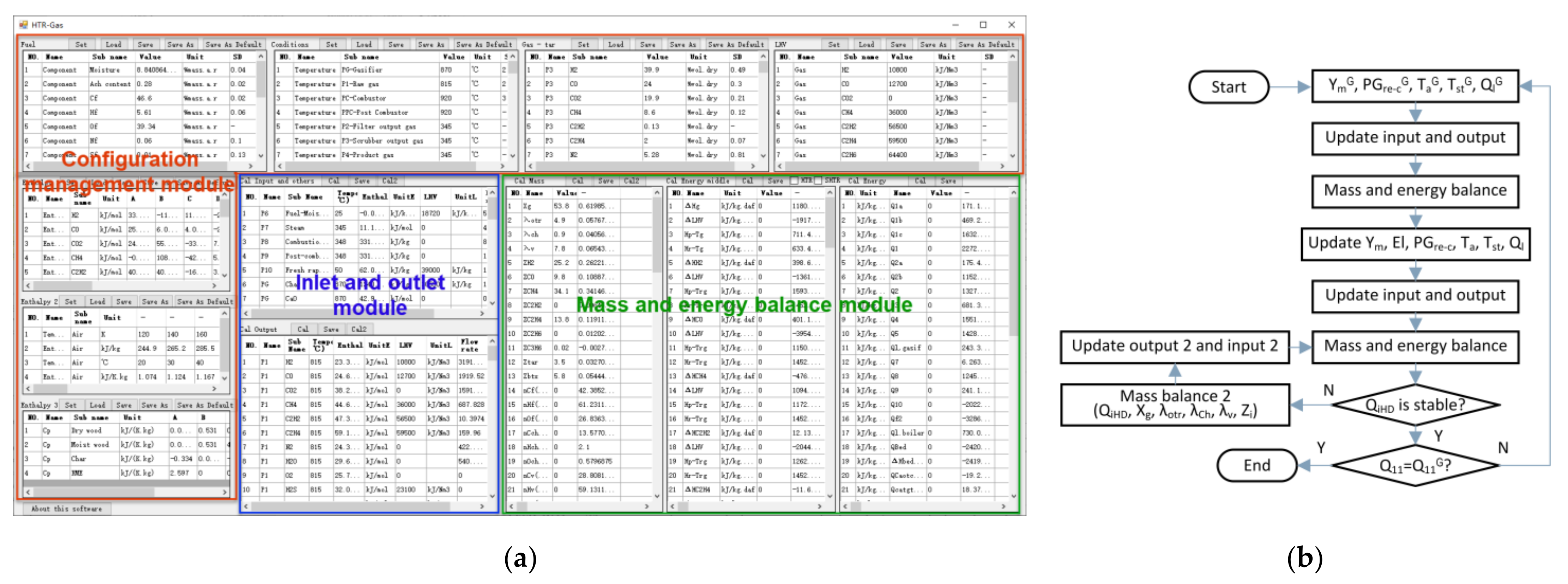
The flow chart for the calculation of the mass balance is shown in Figure 2b. Firstly, we will calculate the molar yields of different elements (carbon, hydrogen and oxygen) in the different substances (biomass, volatiles and char). Then, the stoichiometric coefficients can be obtained for different chemical reactions, char gasification, syngas combustion, volatiles conversion, volatiles combustion and char combustion. According to the components of the raw gas from the DFB, we can calculate the fractions of the volatiles converted to the different burnable compounds in the raw gas except for hydrogen and carbon monoxide. The components of hydrogen and carbon monoxide in the raw gas are also influenced by char gasification. The fraction of char gasified is calculated based on the carbon balance in the gasifier. The fraction of gasified char combusted by oxygen transported from the combustor is obtained based on the assumption of oxygen transport [20]. Then, the fractions of the volatiles converted to hydrogen and carbon monoxide can be obtained by adding the related hydrogen and carbon monoxide from char gasification. Finally, various ratios related to oxygen are calculated.
The methods for calculating the mass balance are introduced in detail by the studies related to the GoBiGas plant [12,20].

3.3.3. Energy Balance of DFB

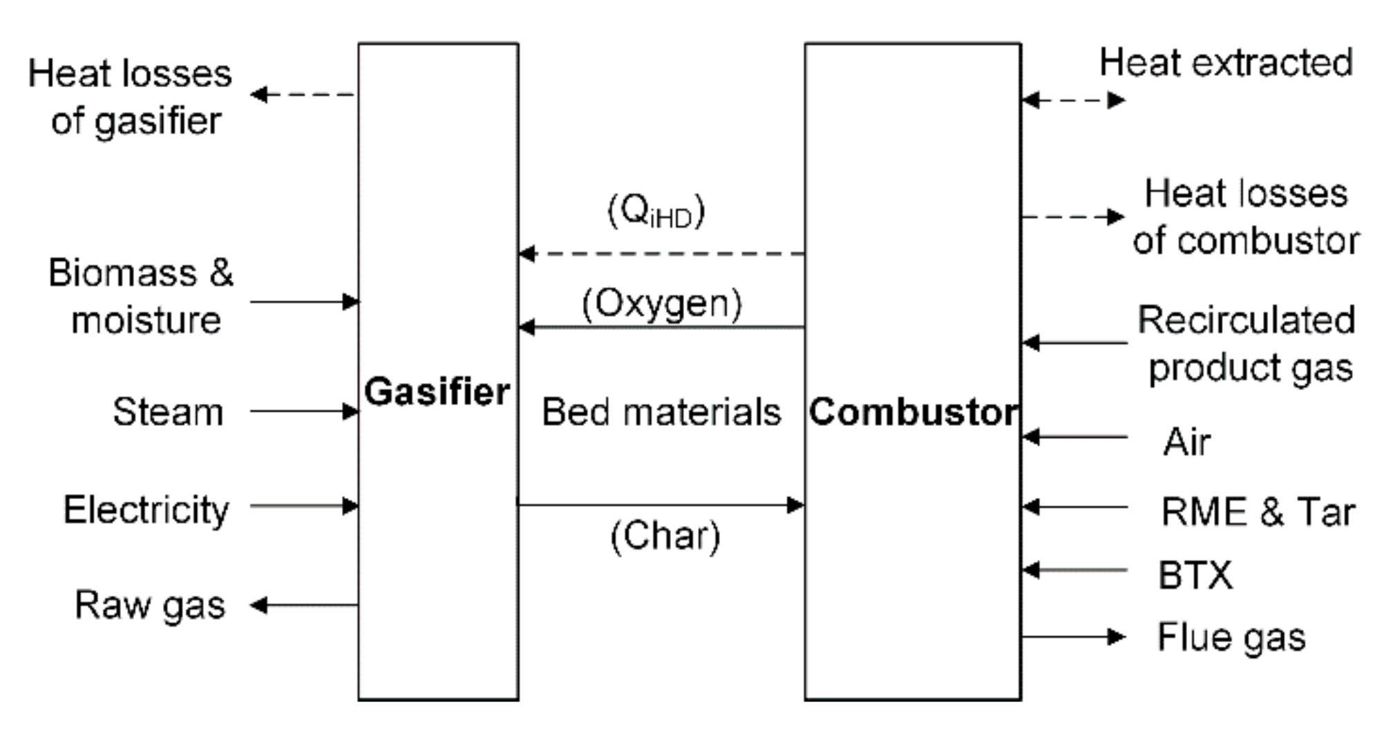
The mass and energy streams and the control volumes considered for the energy balance of the DFB are shown in Figure 3. The input mass streams of the gasifier include biomass, steam and bed materials from the combustor. The output mass streams of the gasifier are raw gas and bed materials to the combustor. The input mass streams of the combustor include air, recirculated product gas, RME, tar, BTX and bed materials from the gasifier. The output mass streams of the combustor include flue gas and bed materials to the gasifier. In addition, we should also consider the heat losses from the gasifier and the combustor to the ambiance and the possible electricity supply to the gasifier.
In particular, the evaluation of the heat losses of the DFB to the ambiance is based on the empirical data of the GoBiGas plant. For the GoBiGas plant, the total heat losses of the gasifier and the combustor to the ambiance are 5.2% LHVdaf [12]. The heat loss of the combustor is around three times that of the gasifier [30], based on their external surfaces and temperatures. For the designs with the same scale of the GoBiGas plant, we assume that their heat losses to the ambiance are also the same. For the large-scale designs, e.g., the HTR-BiGas plant, we assume that the equivalent thermal conductivity in terms of the surface area and the shapes of the reactors is the same as that of the GoBiGas plant, and the volumes and heats of the reactors in the large-scale designs are ten times those in the GoBiGas plant. Thus, we can estimate the total heat losses of the DFB of the large-scale designs at around 2.41% (5.2% × 10(2/3−1)) LHVdaf. Finally, we conservatively set the heat losses of the gasifier and the combustor of the large-scale designs at 0.75% LHVdaf and 2.25% LHVdaf, respectively.
The energy balance first calculates the internal heat demand (QiHD) of the gasifier which is provided by the bed materials from the combustor. The heat demand of the gasifier can be calculated by considering the auxiliary electricity supply, the heat loss of the gasifier to the ambiance and the heat demands of the gasifier for various physical processes and chemical reactions for biomass gasification in Equation (1) as follows:
Q i H D = Q 1 + Q 2 + Q 3 + Q 4 + Q 5 + Q 6 E l
where Q i H D (kJ/kgdaf) = internal heat demand of gasifier in terms of mass of dry ash-free biomass; Q 1 (kJ/kgdaf) = heat demand for biomass drying and heating; Q 2   (kJ/kgdaf) = heat demand for char heating;   Q 3   (kJ/kgdaf) = heat for steam heating; Q 4   (kJ/kgdaf) = heat demand for char gasification; Q 5 (kJ/kgdaf) = heat demand for volatiles conversion; Q 6 (kJ/kgdaf) = heat loss of gasifier to ambiance; E l (kJ/kgdaf) = auxiliary electricity supply to gasifier.
Q i H D should be equal to heat provided to the gasifier by the bed materials from the combustor. However, the energy balance of the combustor usually has an energy deficit [12,16] because the precise prediction of the energy balance for the complex system of the GoBiGas plant is impossible. The energy deficit is counteracted by introducing a heat source named the extracted heat by the combustor. Then, the energy balance of the combustor can be calculated by considering Q i H D , the heat demand for heating various substances, the generated heat by combustion and the heat loss of the combustor to the ambiance in Equation (2) as follows.
Q 11 = Q i H D + Q 7 + Q 8 + Q 9 Q 10 m f 2 L H V f 2 + Q l , C
where Q 11   (kJ/kgdaf) = heat extracted by combustor in terms of mass of dry ash-free biomass; Q 7 (kJ/kgdaf) = heat demand for air heating; Q 8   (kJ/kgdaf) = heat demand for heating recirculated product gas;   Q 9   (kJ/kgdaf) = heat for steam heating; Q 10   (kJ/kgdaf) = heat generated by char combustion; m f 2 (kg/kgdaf) = mass flow of recirculated product gas; L H V f 2 (kJ/kg) = lower heating value of recirculated product gas; Q l , C (kJ/kgdaf) = heat loss of combustor to the ambiance.
When calculating the energy balance for the experimental conditions of the GoBiGas plant, the values of Q i H D can be obtained by Equation (1). Then, Q 11 is calculated by Equation (2). According to the third hypothesis, the Q 11 of HTR-BiGas or similar designs should be equal to that of GoBiGas. Finally, we can calculate the mass and energy balances of HTR-BiGas and other related designs with Equations (1) and (2).
Then, we can calculate various efficiencies as follows:
η R G = R G m i L H V i L H V f
where η R G (% L H V d a f ) = raw gas (RG) efficiency; m i (kg/kgdaf) = mass of raw gas compound i in terms of mass of dry ash-free biomass (raw gas includes all burnable gas, e.g., H2, CO, CH4, C2H2, C2H4, C2H6, C3H6, tar, BTX, etc.); L H V i (kJ/kg) = lower heating value of raw gas compound i; L H V f (kJ/kgdaf) = lower heating value of dry ash-free biomass.
η C G = C G m j L H V j L H V f
where η C G (% L H V d a f ) = cold gas (CG) efficiency; m j (kg/kgdaf) = mass of permanent gas compound j in terms of mass of dry ash-free biomass (permanent gas includes H2, CO, CH4, C2H2, C2H4, C2H6, C3H6, etc.); L H V j (kJ/kg) = lower heating value of permanent gas compound j.
η s e c t = C G m j L H V j L H V f + m R M E L H V R M E + E l t o t a l + Q H T R
where η s e c t (% E t o t a l ) = gasification section (DFB) efficiency; m R M E (kg/kgdaf) = mass of RME in terms of mass of dry ash-free biomass; L H V R M E (kJ/kg) = lower heating value of RME; E l t o t a l (kJ/kgdaf) = total electricity used in the plant; Q H T R (kJ/kgdaf) = thermal heat provided by HTR.
η p l a n t = F G m k L H V k L H V f + m R M E L H V R M E + E l t o t a l + Q H T R
where η p l a n t (% E t o t a l ) = plant efficiency; m k (kg/kgdaf) = mass of final product gas compound k (hydrogen and SNG) in terms of mass of dry ash-free biomass; L H V k (kJ/kg) = lower heating value of final product gas compound k.
In this way, we can discuss the energy balances of the three designs: electric auxiliary heating, increasing recirculated product gas and heating inlet steam by HTR for biomass gasification.
The methods for calculating the energy balance are introduced in detail by the studies related to the GoBiGas plant [12,20].

3.4. Calculation Software

We developed a software using Visual Basic.Net by Microsoft (Redmond, Washington, USA) to calculate the mass and energy balances of the various designs, e.g., GoBiGas, HTR-BiGas, etc., for biomass gasification.
The main interface of the software is shown in Figure 4a. The modules of the software and their main functions are explained as follows:
  • Configuration management module: manage the configurations of the biomass gasification plant and the physical and chemical properties of the related substances.
  • Inlet and outlet module: calculate the values of the input and output streams of different equipment.
  • Mass and energy balance module: calculate the mass and energy balances of different equipment.
The flow chart for the calculation is shown in Figure 4b. Because the calculation of the mass and energy balances is conducted based on the experimental conditions of the GoBiGas plant, the configurations are first set to the experimental conditions of the GoBiGas plant [12], e.g., the moisture content of the biomass, the fraction of the circulated product gas, the temperatures of the inlet air and steam, the heat losses of the DFB to the ambiance, etc. After updating the various inputs and outputs, e.g., enthalpies and flow rates of the inlet air, the inlet steam and the product gas, etc., the mass and energy balances are calculated to initialize the software to the experimental conditions of the GoBiGas plant.
After this, the configurations are set to the conditions of the different designs, e.g., HTR-BiGas. The mass and energy balances are calculated after updating the related inputs and outputs. The new value of Q i H D is compared with its value in the last step. If the value of Q i H D is not stable, we need to calculate the new fractions of different components of the raw gas that are oxidized by changing the oxygen transported by the bed materials from the combustor. The mass and energy balances are calculated again by updating the various outputs and inputs until the value of Q i H D becomes stable. Then, the value of Q 11 will be compared with that under the experimental conditions of the GoBiGas plant. If these two values are not the same, indicating that the energy balance of the related design is not achieved, we should modify the related parameters, the introduced auxiliary electricity for heating biomass or the recirculation fraction of the product gas. Finally, we can obtain the values of related parameters and the efficiencies of different designs.

3.5. Economic Evaluation

The economy of a plant to produce the burnable gas can be evaluated by its full life-cycle costs, namely, levelized costs of energy (LCOE) [31] of the final product gas. The LCOEs of HTR-BiGas and other designs can be calculated by Equation (7) as follows:
L C O E = S C d e p + S C i n t + S C d e v + S C o & m + S C f
where L C O E ($/MWh) = levelized costs of energy of final product gas; S C d e p ($/MWh) = specific investment cost related to depreciation; S C i n t ($/MWh) = specific investment cost related to interest; S C d e v ($/MWh) = specific development cost; S C o & m ($/MWh) = specific operation and maintenance (O&M) cost; S C f ($/MWh) = specific fuel-related cost.
The different specific costs are calculated according to the methods of the study related to the GoBiGas plant [13].
The specific investment cost related to depreciation can be obtained according to Equation (8) as follows:
S C d e p = 10 i C i n v , i E p Y l H f l + j C i n v , j E p Y l 2 Y f l
where C i n v , i ($) = investment cost of component i in biomass gasification module; C i n v , j ($) = investment cost of component j in steam supply module; E p (MW) = thermal power of final product gas; Y l (year) = expected lifetime of biomass gasification module; Y l 2 (year) = expected lifetime of steam supply module; H f l (hour/year) = expected annual full-load hours of plant.
The specific investment cost related to interest can be calculated by Equation (9) as follows:
S C i n t = 10 i C i n v , i E p Y l H f l Y l I n t 1 1 + I n t Y l 1 + j C i n v , j E p Y l 2 H f l Y l 2 I n t 1 1 + I n t Y l 2 1
where I n t = interest rate.
The specific development cost is calculated by Equation (10) as follows:
S C d e v = θ d e v S C d e p
where θ d e v = development factor.
The specific O&M cost can be obtained according to Equation (11) as follows:
S C o & m = i C o & m , i + j C o & m , j E p H f l
where C o & m , i ($) = annual O&M cost of component i in biomass gasification module; C o & m , j ($) = annual O&M cost of component j in steam supply module.
The specific fuel-related cost can be obtained according to Equation (12) as follows:
S C f = 10 C b i o v d a f E p 1 ω + C n u c E p H f l
where C b i o ($/kg) = specific cost of as-received biomass; v d a f (kgdaf/h) = mass flow of dry ash-free biomass fed to a gasifier; ω = moisture content of as-received biomass; C n u c ($/year) = annual cost of nuclear fuel for an HTR.
The thermal power of the final product gas is calculated regarding the values of the LHV (low heating value) and the flow rate of product gas by Equation (13) as follows:
E p = 10 L H V H 2 v P 17 φ H 2 + L H V C H 4 v P 16 φ C H 4 3600 × 1000
where L H V H 2 (kJ/Nm3) = lower heating value of hydrogen; v P 17 (Nm3/h) = volume flow rate of final product gas at P17 in a biomass gasification module; φ H 2 = volume fraction of hydrogen in final product gas at P17; L H V C H 4 (kJ/Nm3) = lower heating value of methane; v P 16 (Nm3/h) = volume flow rate of final product gas at P16 in a biomass gasification module; φ C H 4 = volume fraction of methane in final product gas at P16.
The cost to produce hydrogen or SNG can be determined by assuming the same specific costs of hydrogen and SNG in terms of their heat.
The specific production cost of hydrogen can be calculated according to Equation (14) as follows:
S C H 2 = L H V H 2 φ H 2 E p L O C E 10 L H V H 2 v P 17 φ H 2 + L H V C H 4 v P 16 φ C H 4
where S C H 2 ($/Nm3) = specific production cost of hydrogen.
The specific production cost of SNG can be calculated according to Equation (15) as follows:
S C S N G = L H V C H 4 φ C H 4 E p L O C E 10 L H V H 2 v P 17 φ H 2 + L H V C H 4 v P 16 φ C H 4
where S C S N G ($/Nm3) = specific production cost of SNG.
It should be noted that HTR-PM is currently in the stage of the demonstration plant, and its cost will be relatively high. The cost data of the HTR for the steam supply module mainly derive from those of the predicted commercialized plant of HTR-PM [22]. Similarly, the commercialization of GoBiGas has not yet been realized. We choose the costs of the predicted scale-up of the GoBiGas plant [13]. Here, we also consider the fact that the price of various equipment and the costs of construction, operation and maintenance will be relatively low when it is built and operated in China. Thus, we make reasonable adjustments in the related costs.
The values of some parameters for the economic evaluation used in Equations (8)–(12) are shown in Table 3. The expected lifetime of the biomass gasification module is predicted as 20 years, the same as that of the GoBiGas plant [11]. The expected lifetime of the steam supply module including an HTR is set as 40 years, the normal lifetime of a nuclear power plant. We suppose that another 10 biomass gasification modules will be constructed after the first 20 years of operation and their various costs are the same as those of the first 10 biomass gasification modules. The additional costs, e.g., retirement costs, can be covered by the incomes from retrieving the reusable material and equipment, etc.

4. Results

4.1. Mass Balance

Table 4 shows the calculation results of the mass balances of HTR-BiGas and related designs for co-generation of hydrogen and SNG where the moisture content of the biomass is 40%. We also calculate the mass balances of GoBiGas and the co-generation design using the biomass with a moisture content of 8% whose configurations of the DFB unit are the same.
In general, the results of the mass balances of GoBiGas and the similar co-generation design using the same biomass with a moisture content of 8% are comparable. The differences between them may be mainly introduced by the differences in physical and chemical properties of related substances and the methods for calculating the mass balance in detail. The mole yields of carbon, hydrogen and oxygen in biomass and char are different in different articles [12,20] which are sensitive to the results of mass balance. Besides, several methods are introduced for determining some important parameters [20] but the final adoptions in the related literature are not revealed [12].
Here, we consider three different countermeasures for dealing with the high moisture content of the biomass: electric auxiliary heating, increasing recirculated product gas and heating inlet steam by HTR. The introduction of the electric auxiliary heating has little influence on the biomass gasification coefficient, the syngas and volatiles combustion and the fraction of the transported oxygen from the combustor to the gasifier. The increase of the recirculated product gas and the heating of the inlet steam increase the syngas and volatiles combustion by increasing the oxygen transported from the combustor to the gasifier so they decrease the burnable contents in the raw gas from the gasifier.
The main contents of the final product gas produced by a biomass gasification module are calculated in Table 5. The energy of SNG in terms of its flow rate and LHV accounts for around 45% energy of the final product gas (hydrogen and SNG). The designs of electric auxiliary heating have the highest output power regarding the final product gas. The designs of increasing recirculated product gas produce the least final product gas by combusting the most recirculated product gas in the combustor.

4.2. Energy Balance

Table 6 and Figure A1 show the calculation results of the energy balances of HTR-BiGas and the related designs for co-generation of hydrogen and SNG using the biomass with a moisture content of 40%. We also calculated the energy balance of the co-generation design using the biomass with a moisture content of 8% whose configurations of the DFB unit are the same as those of GoBiGas. These results are compared with those of GoBiGas and related simulated cases [12] (Table 6 and Figure A1).
In general, the results of the energy balances of GoBiGas and the similar co-generation design using the same biomass with a moisture content of 8% are comparable. The biggest difference occurs at the plant efficiency because GoBiGas produces only SNG and our design co-produces SNG and hydrogen where a similar co-generation design usually has a higher efficiency [21].
The plant efficiency of the GoBiGas plant will drop to around 45% without any countermeasures when using the unpretreated biomass with a moisture content of 40% [12]. The plant efficiencies are all above 52% for other cases. The co-generation design whose dual fluidized bed unit is the same as that of GoBiGas has a plant efficiency of 52.72% for the biomass with a moisture content of 40%. Related studies had indicated that the co-generation systems often have higher production efficiencies than the systems only producing SNG [11,13].
The designs of electric auxiliary heating usually have the highest efficiencies. Electric auxiliary heating injects the auxiliary electricity into the gasifier directly while the other two designs need to transport the added heat (a part or all) through the bed materials from the combustor. In addition, when the heat is transported from HTR to the gasifier, some additional heat exchangers are needed where the heat losses to the ambiance cannot be ignored. Heating inlet steam by HTR has higher raw gas and cold gas efficiencies than increasing recirculated product gas. These two designs have close gasification section efficiencies and plant efficiencies. The countermeasures by increasing recirculated product gas usually have the highest internal heat demand of gasifier and the highest energy of recirculated product gas.
The various efficiencies often increase with the increase in the scale of the design except for the design of electric auxiliary heating. The reason is much higher auxiliary electricity per biomass is needed for heating the biomass in the smaller gasifier so the raw gas and cold gas efficiencies become higher for the small gasifier.

4.3. Economic Evaluation

The estimated costs of different components of HTR-BiGas and the other two large-scale designs are summarized in Table 7. The other two designs of electric auxiliary heating and increasing recirculated product gas do not have an independent steam supply module. Besides, we only consider the O&M cost related to waste treatment and materials expenses of the HTR.
The results of the economic evaluations of HTR-BiGas and other designs are presented in Table 8. Here, we discuss the specific costs in terms of the heat (MWh), the standard volume (Nm3) and the mass (kg) of the final product gas. HTR-BiGas obtains the best economic performance. Although the investment-related costs and the fuel-related cost of HTR-BiGas are higher than those of the other two designs (Table 7), its related specific costs are in the middle or close to those of the increasing recirculated product gas because of its related higher final production (Table 5). Because the O&M cost (including electricity fee) of HTR-GoBiGas is much lower than that of the other two designs, the LOCE and specific costs for producing hydrogen and SNG for it are all the lowest ones. The design of electric auxiliary heating is mainly hurt by the high electric charge. The increase of recirculated product gas combusts more product gas, resulting in much lower final production.
Figure 5a compares production costs of HTR-BiGas and the other two designs with the average price of Chinese imported LNG in 2019 [14] and the break-even prices of the coal-based SNG [16]. Although the prices of imported pipeline natural gas (PNG) were lower than those of imported LNG, their actual costs were close because of the high transport cost of imported PNG [14]. Regional factors determine the economy of coal-based SNG projects, so the projects in Xinjiang and Inner Mongolia have good economic performance, mainly due to the lower prices of coal. The production costs of hydrogen are also compared for our designs, the coal gasification technology and the production technology by using natural gas (Figure 5b) [17,32]. The costs to produce hydrogen by coal and natural gas mainly depend on the prices of coal and hydrogen where the fuel costs of these mainstream technologies usually occupy around 50–80% of their total costs.

5. Discussion

This article proposed a 200 MWth × 10 co-generation design, HTR-BiGas, to produce hydrogen and SNG by integrating the state-of-the-art DFB and HTR technologies from GoBiGas and HTR-PM. HTR-BiGas aims to improve the production efficiency and economy of biomass gasification by heating inlet steam of the gasifier with the high-temperature carbon-free steam from the HTR to cope with the unpretreated biomass with a moisture content of 40%. The production efficiency will drop to around 45% without any countermeasures [12].
By designing and developing Visual Basic. Net software, we conducted the calculation of the mass and energy balances of GoBiGas, HTR-BiGas and the other gas co-generation designs of heating inlet steam by HTR, electric auxiliary heating and increasing recirculated product gas. Agreements between our calculation results on the mass and energy balances of GoBiGas and the similar co-generation design show the reasonability and applicability of the software (Table 4 and Table 6). Then, the technical and economic evaluations were carried out to compare countermeasures on different scales (20 MWth and 200 MWth × 10) for dealing with the unpretreated biomass (moisture content of 40%), heating inlet steam by HTR, electric auxiliary heating and increasing recirculated product gas.
All of the large-scale designs (200 MWth × 10) showed proper production efficiencies (more than 55%) based on the calculation results of their mass and energy balances. Electric auxiliary heating usually has the highest production efficiencies because it heats the biomass in the gasifier directly. HTR-BiGas and increasing recirculated product gas have close efficiencies because they have to transport a part or all of the added heat through the bed materials from the combustor. HTR-BiGas also loses some heat when transferring the heat from the HTR to the DFB. Besides, HTR-BiGas and electric auxiliary heating have higher total productions of final product gas than increasing recirculated product gas. The design of increasing recirculated product gas combusts a bigger fraction of recirculated product gas in the combustor, and therefore the final product gas of it is the least one.
Preliminary economic evaluation based on the LOCE method indicated that all large-scale designs including HTR-BiGas, electric auxiliary heating and increasing recirculated product gas had proper production costs for co-generation of hydrogen and SNG in China. When the electricity price is 0.15 $/kWh, the costs for producing hydrogen by these three designs are 1.62 $/kg, 1.90 $/kg and 1.72 $/kg, coupling with the costs for producing SNG, 0.430 $/Nm3, 0.505 $/Nm3 and 0.456 $/Nm3, respectively. By comparison, the break-even prices of the coal-based SNG are around 0.355–0.509 $/Nm3, mainly depending on the coal prices at the locations of the SNG projects [16]. In 2019, the average price of Chinese imported LNG was 0.415 $/Nm3 [14]. The actual cost of imported PNG is close to that of imported LNG because its transport cost is higher when transporting the imported natural gas to the main users in Eastern China [14]. Production costs of hydrogen by coal and natural gas are 1.19–2.04 $/kg and 1.54–2.94 $/kg when the prices of coal and natural gas are 61.7–123.4 $/t and 0.309–0.617 $/Nm3, respectively [17]. Another study also indicated that production costs of hydrogen by coal and natural gas are 0.86–1.89 $/kg and 1.36–3.50 $/kg [32]. At present, the Chinese mainstream technologies produce SNG or hydrogen by using the fossil fuel of coal or natural gas.
In general, the production costs of HTR-BiGas and the other two designs are comparative with those of mainstream production techniques and the imported natural gas in China. Our proposed designs mainly benefit from proper production efficiencies with low fuel-related costs due to the cheap unpretreated biomass (moisture content of 40%, around 31 $/ton). In addition, these designs have much lower carbon emissions than the mainstream technologies utilizing coal or natural gas.
Among them, HTR-BiGas obtains the best economic performance. The design of electric auxiliary heating is hurt by the higher electric charge and the shortcoming of increasing recirculated product gas is its lower total production. The decrease in electricity price can significantly reduce the production cost of electric auxiliary heating. Thus, the design of electric auxiliary heating may have more advantages in the Midwest of China.
The main shortcoming of HTR-BiGas is the relatively low temperature (450 °C) of the inlet steam which is limited by the present design, which combines an SG and an IHX to heat the inlet steam of the gasifier. Some of the additional heat to heat the biomass is transported by the bed materials from the combustor by increasing the recirculated product gas, which decreases the power of the final product gas and the plant efficiency of HTR-BiGas.
An intermediate loop is usually adopted to provide physical separation between the nuclear reactor system and other energetic cycle processes [33]. HTR-BiGas also has the intermediate loop coping with an SG and an IHX. If a strong SG can directly heat the inlet steam of the gasifier with the helium from the HTR, the temperature of the inlet steam will be around 570 °C which can increase the plant efficiency by around 2.5%. However, the corrosion of the SG tubes and the deposits on them cannot be ignored even in the highly purified conditions of the nuclear reactor system [34,35]. It is not economically feasible to make the water for biomass gasification highly purified. The purity of the water/steam used for the gasifier will be lower than that in the nuclear reactor system so the problems related to corrosion and deposits will greatly challenge the design of the SG to substitute for the intermediate loop. This SG has to simultaneously cope with the radioactive primary loop and the relatively low purity water/steam in the secondary side.
On the other hand, the optimization of the IHX of the high-temperature engineering test reactor (HTTR) was recently performed by using innovative materials and a different primary coolant to increase the outlet temperature of its secondary side for hydrogen production [36]. INET was also researching to increase the outlet temperature of HTR for hydrogen production, heat and power co-generation, etc. [37]. The increase of the related outlet temperature of the HTR or the SG/IHX can raise the temperature of the inlet steam of the gasifier, finally increasing the power of the final product gas and the plant efficiency. However, there are still various challenges in materials and thermal-hydraulic and power conversion designs [33].
Some fundamental experiments should be conducted by using the local biomass in China, e.g., various crop stalks, etc., by constructing a small-scale test facility based on the technologies of GoBiGas. The experiments and related analysis works will determine whether a large-scale demonstration project can be constructed to co-produce 200 MWth hydrogen and SNG where the different countermeasures can be tested. The final object of our study is to construct the 200 MWth × 10 biomass gasification system with an HTR even if it has a long way to go.

6. Conclusions and Future Work

We proposed a large-scale biomass gasification system (200 MWth × 10) for co-generation of hydrogen and SNG by combining dual fluidized bed and high-temperature gas-cooled reactor to gasify the unpretreated biomass with a moisture content of 40%.
Software for calculating the mass and energy balances of biomass gasification was developed and validated by the experimental results on the GoBiGas plant. Our design to heat inlet steam by HTR and the other two possible designs, electric auxiliary heating and increasing recirculated product gas, are economically comparative with those of mainstream production techniques using fossil fuels and the imported natural gas in China. The costs for producing hydrogen are 1.62 $/kg, 1.90 $/kg and 1.72 $/kg, respectively, coupling with the costs for producing SNG, 0.430 $/Nm3, 0.505 $/Nm3 and 0.456 $/Nm3 when the price of electricity is 0.15 $/kWh. These designs with low carbon emissions have proper production efficiencies of more than 55% when gasifying the cheap unpretreated biomass with a moisture content of 40%.
The design to heat the inlet steam of the gasifier by HTR has economic advantages over the other two possible designs by using the high-quality and low-carbon heat from HTR. The design of electric auxiliary heating is mainly influenced by the high electric charge. The increase of recirculated product gas combusts more product gas, resulting in much lower final production.
Although facing various challenges, the increase of the outlet temperature of HTR and the adoption of a powerful steam generator that can substitute for the intermediate loop will improve the production efficiency and economy of HTR-BiGas by raising the temperature of the inlet steam of the gasifier. In addition, the experiment works are predicted to include the construction of a small test facility to use Chinese local biomass and then a following 200 MWth demonstration project to optimize the related designs.

Author Contributions

Conceptualization, Y.Z.; methodology, Y.Z. and Z.G.; software, Y.Z.; validation, Y.Z. and Z.G.; formal analysis, Y.Z.; investigation, Y.Z., Z.G. and F.X.; resources, Y.Z.; data curation, Y.Z.; writing—original draft preparation, Y.Z. and Z.G.; writing—review and editing, Y.Z.; visualization, Y.Z.; supervision, Y.D.; project administration, Y.D. and Y.Z.; funding acquisition, Z.Z. All authors have read and agreed to the published version of the manuscript.

Funding

The research was funded by Chinese Major National S&T, Grant number ZX069.

Data Availability Statement

The datasets generated during the study are available at https://github.com/zhouyp97/HTR-BiGas.

Acknowledgments

We thank Feng Chen, Institute of Nuclear and New Energy Technology, Tsinghua University, for providing supports for this study.

Conflicts of Interest

The authors declare no conflict of interest.

Appendix A. Efficiencies, Heats and Powers of Product Gas of GoBiGas, HTR-BiGas and Related Designs

Figure A1. Efficiencies, heats and powers of product gas of GoBiGas, HTR-BiGas and related designs. (a) Efficiency; (b) heat; (c) power of final product gas of a biomass gasification module. ω: moisture content of biomass; GoBiGas: Gothenburg biomass gasification; G-C: co-generation design whose biomass gasification unit is the same as that of GoBiGas; H: heating inlet steam and air; Q: decreasing heat losses of combustor and gasifier; E: electric auxiliary heating; R: increasing recirculated product gas; HTR: heating inlet steam by HTR; HTR-BiGas: high-temperature gas-cooled reactor biomass gasification; η R G : raw gas (RG) efficiency; η C G : cold gas (CG) efficiency; η s e c t : gasification section efficiency; η p l a n t : plant efficiency; L H V d a f : lower heating value of dry ash-free biomass; Q i H D : internal heat demand of gasifier; E P G . r e : energy of recirculated product gas; E l : auxiliary electricity supply to gasifier.
Energies 14 05683 g0a1

References

  1. Ahrenfeldt, J.; Thomsen, T.P.; Henriksen, U.; Clausen, L.R. Biomass gasification cogeneration—A review of state of the art technology and near future perspectives. Appl. Therm. Eng. 2013, 50, 1407–1417. [Google Scholar] [CrossRef] [Green Version]
  2. Karl, J.; Pröll, T. Steam gasification of biomass in dual fluidized bed gasifiers: A review. Renew. Sustain. Energy Rev. 2018, 98, 64–78. [Google Scholar] [CrossRef]
  3. Hanchate, N.; Ramani, S.; Mathpati, C.S.; Dalvi, V.H. Biomass gasification using dual fluidized bed gasification systems: A review. J. Clean. Prod. 2021, 280, 123148. [Google Scholar] [CrossRef]
  4. Corella, J.; Toledo, J.M.; Molina, G. A Review on Dual Fluidized-Bed Biomass Gasifiers. Ind. Eng. Chem. Res. 2007, 46, 6831–6839. [Google Scholar] [CrossRef]
  5. Guerrini, O.; Gaillard, M.; Peureux, G.; Kara, Y.; Marchand, B.; Perrin, M.; Aubigny, A.; da Silva Perez, D.; Guinard, L.; Commandre, J.-M.; et al. Gaya demonstration project: Towards industrialization of an innovative and integrated 2nd generation bioSNG pathway through biomass gasification. In Proceedings of the WasteEng 2014—5th International Conference on Engineering for Waste and Biomass Valorisation, Rio de Janeiro, Brazil, 25–28 August 2014; Nzihou, A., Guerreiro, S., Eds.; MINES ALBI: Albi, France, 2014; pp. 734–741. [Google Scholar]
  6. Bolhar-Nordenkampf, M.; Bosch, K.; Rauch, R.; Kaiser, S.; Tremmel, H.; Aichernig, C.; Hofbauer, H. Scale-up of a 100 kWth pilot FICFB-gasifier to a 8 MWth FICFB-gasifier demonstration plant in Güssing. In Proceedings of the 1st Ukrainian Conference on Biomass for Energy, Kiev, Ukrain, 30 September 2002. [Google Scholar]
  7. Technical University of Denmark. Low Temperature Biomass Gasification: Fuel Flexible, Efficient and Sustainable; Department of Chemical and Biochemical Engineering, Technical University of Denmark: Copenhagen, Denmark, 2017. [Google Scholar]
  8. Rabou, L.; Overwijk, M. The Alkmaar 4 MW bio-SNG demo project. In Proceedings of the 3rd International Conference on Renewable Energy Gas Technology, Malmö, Sweden, 10–11 May 2016; Energieonderzoek Centrum Nederland: Petten, The Netherlands, 2016. [Google Scholar]
  9. Thunman, H.; Seemann, M.; Vilches, T.B.; Maric, J.; Pallares, D.; Ström, H. Advanced biofuel production via gasification—Lessons learned from 200 man-years of research activity with Chalmers’ research gasifier and the GoBiGas demonstration plant. Energy Sci. Eng. 2018, 6, 6–34. [Google Scholar] [CrossRef]
  10. Pio, D.T.; Tarelho, L.A.C. Industrial gasification systems (>3 MWth) for bioenergy in Europe: Current status and future perspectives. Renew. Sustain. Energy Rev. 2021, 145, 111108. [Google Scholar] [CrossRef]
  11. Thunman, H.; Seemann, M. The GoBiGas plant. In Substitute Natural Gas from Waste; Materazzi, M., Foscolo, P.U., Eds.; Academic Press: Pittsburgh, PA, USA, 2019; pp. 455–474. [Google Scholar] [CrossRef]
  12. Alamia, A.; Larsson, A.; Breitholtz, C.; Thunman, H. Performance of large-scale biomass gasifiers in a biorefinery, a state-of-the-art reference. Int. J. Energy Res. 2017, 41, 2001–2019. [Google Scholar] [CrossRef]
  13. Thunman, H.; Gustavsson, C.; Larsson, A.; Gunnarsson, I.; Tengberg, F. Economic assessment of advanced biofuel production via gasification using cost data from the GoBiGas plant. Energy Sci. Eng. 2019, 7, 217–229. [Google Scholar] [CrossRef]
  14. Ying, J.; Chen, D. Research on the China’s natural gas import price difference and reducing cost countermeasures. Price Theory Pract. 2020, 2020, 47–51. [Google Scholar] [CrossRef]
  15. Zhang, X.; Liu, Z. Analysis and discussion on development of coal-to-natural gas project in China. Hans J. Chem. Eng. Technol. 2013, 3, 42–47. [Google Scholar] [CrossRef]
  16. Zeng, S.; Gu, J.; Yang, S.; Zhou, H.; Qian, Y. Comparison of techno-economic performance and environmental impacts between shale gas and coal-based synthetic natural gas (SNG) in China. J. Clean. Prod. 2019, 215, 544–556. [Google Scholar] [CrossRef]
  17. Chai, S.; Zhang, G.; Li, G.; Zhang, Y. Industrial hydrogen production technology and development status in China: A review. Clean Technol. Environ. Policy 2021, 23, 1931–1946. [Google Scholar] [CrossRef]
  18. Zhang, Z.; Dong, Y.; Li, F.; Zhang, Z.; Wang, H.; Huang, X.; Li, H.; Liu, B.; Wu, X.; Wang, H.; et al. The Shandong Shidao Bay 200MWe high-temperature gas-cooled reactor pebble-bed module (HTR-PM) demonstration power plant: An engineering and technological innovation. Engineering 2016, 2, 112–118. [Google Scholar] [CrossRef] [Green Version]
  19. Gassner, M.; Marechal, F. Thermodynamic comparison of the FICFB and Viking gasification concepts. Energy 2009, 34, 1744–1753. [Google Scholar] [CrossRef] [Green Version]
  20. Alamia, A.; Thunman, H.; Seemann, M. Process simulation of dual fluidized bed gasifiers using experimental data. Energy Fuels 2016, 30, 4017–4033. [Google Scholar] [CrossRef]
  21. Alamia, A.; Òsk Gardarsdòttir, S.; Larsson, A.; Normann, F.; Thunman, H. Efficiency comparison of large-scale standalone, centralized, and distributed thermochemical biorefineries. Energy Technol. 2017, 5, 1435–1448. [Google Scholar] [CrossRef] [Green Version]
  22. Wang, Y. Study on Economic and Other Key Issues for the Commercialization of High Temperature Gas-Cooled Reactors. Ph.D. Thesis, Tsinghua Univesity, Beijing, China, June 2017. [Google Scholar]
  23. Nikolaidis, P.; Poullikkas, A. A comparative overview of hydrogen production processes. Renew. Sustain. Energy Rev. 2017, 67, 597–611. [Google Scholar] [CrossRef]
  24. Mäkelä, M.; Fullana, A.; Yoshikawa, K. Ash behavior during hydrothermal treatment for solid fuel applications. Part 1: Overview of different feedstock. Energy Convers. Manag. 2016, 121, 402–408. [Google Scholar] [CrossRef]
  25. Larsson, A.; Seemann, M.; Neves, D.; Thunman, H. Evaluation of performance of industrial-scale dual fluidized bed gasifiers using the chalmers 2–4-MWth gasifier. Energy Fuels 2013, 27, 6665–6680. [Google Scholar] [CrossRef]
  26. Merkisz, J.; Fuć, P.; Lijewski, P.; Kozak, M. Rapeseed oil methyl esters (RME) as fuel for urban transport. In Alternative Fuels, Technical and Environmental Conditions; Bicrnat, K., Ed.; IntechOpen: London, UK, 2016. [Google Scholar]
  27. Elmer, J.; Huber, J.; Charles, E.; Holley, J. The heat of combustion of calcium. J. Phys. Chem. 1956, 60, 498–499. [Google Scholar] [CrossRef]
  28. Thermochemical Data. In NIST Chemistry WebBook, NIST Standard Reference Database Number 69. Available online: https://webbook.nist.gov/chemistry/ (accessed on 2 March 2021).
  29. Giuliano Albo, P.A.; Lago, S.; Wolf, H.; Pagel, R.; Glen, N.; Clerck, M.; Ballereau, P. Density, viscosity and specific heat capacity of diesel blends with rapeseed and soybean oil methyl ester. Biomass Bioenergy 2017, 96, 87–95. [Google Scholar] [CrossRef]
  30. Karlbrink, M. An Evaluation of the Performance of the GoBiGas Gasificaiton Process. Master’s Thesis, Chalmers University of Technology, Gothenburg, Sweden, 2015. [Google Scholar]
  31. Bruck, M.; Sandborn, P.; Goudarzi, N. A levelized cost of energy (LCOE) model for wind farms that include power purchase agreements (PPAs). Renew. Energy 2018, 122, 131–139. [Google Scholar] [CrossRef]
  32. El-Emam, R.S.; Ozcan, H. Comprehensive review on the techno-economics of sustainable large-scale clean hydrogen production. J. Clean. Prod. 2019, 220, 593–609. [Google Scholar] [CrossRef]
  33. Sabharwall, P.; Bragg-Sitton, S.M.; Stoots, C. Challenges in the development of high temperature reactors. Energy Convers. Manag. 2013, 74, 574–581. [Google Scholar] [CrossRef]
  34. Rodriguez, M.A. Corrosion control of nuclear steam generators under normal operation and plant-outage conditions: A review. Corros. Rev. 2020, 38, 195–230. [Google Scholar] [CrossRef]
  35. D’Angelo, R.; Roy, M.; Pauporte, T.; Delaunay, S.; You, D.; Mansour, C.; Miserque, F.; Foct, F. Study of the effect of polyacrylic acid dispersant on magnetite deposits in steam generators conditions. Mater. Chem. Phys. 2019, 226, 118–128. [Google Scholar] [CrossRef]
  36. Bolfo, L.; Devia, F.; Lomonaco, G. Nuclear hydrogen production: Modeling and preliminary optimization of a helical tube heat exchanger. Energies 2021, 14, 3133. [Google Scholar] [CrossRef]
  37. Sun, S.; Zhang, Y.; Zheng, Y.; Xia, B. Core temperature districtions in HTR-10 operating at very high tmperatures. J. Tsinghua Univ. (Sci. Technol.) 2020. [Google Scholar] [CrossRef]
Figure 1. Design of high-temperature gas-cooled reactor biomass gasification (HTR-BiGas): P1. hot raw gas; P2. particle-free gas; P3. cold gas; P4. product gas; P5. flue gas; P6. fuel feed; P7. steam feed; P8. air feed; P9. rapeseed oil methyl (RME); P10. high-pressure gas; P11. sulfur-free gas; P12. rich H2 gas; P13. CO2 removal gas; P14. methanation gas; P15. rich CH4 gas; P16. synthetic natural gas; P17. H2. (BTX: benzene, toluene and xylene; WGS: water gas shift; VPSA: vacuum pressure swing adsorption; TSA: temperature swing adsorption).
Energies 14 05683 g001
Figure 2. Pyrolysis process and chemical reactions of biomass gasification in dual fluidized bed and flow chart for calculating mass balance in them. (a) Pyrolysis process and chemical reactions; (b) flow chart for calculating mass balance. ( ( n x ) y : molar yield of element x (C: carbon; H: hydrogen; O: oxygen) in related substance y (f: biomass; v: volatiles; ch: char); Y c h : char yield; X g : fraction of char gasified; λ c h : fraction of char gasified and then combusted; λ v : fraction of volatiles combusted; Z i : fraction of volatiles converted to raw gas compound i (H2, CO, CH4, C2H2, C2H4, C2H6, tar, BTX (benzene, toluene and xylene), etc.); a m , b m , c m , d m : stoichiometric coefficients of chemical reaction m (1: char gasification; 2: syngas combustion; 3: volatiles conversion; 4: volatiles combustion; 5: char combustion); λ a : air-to-fuel equivalence ratio; λ O t r : transported oxygen to fuel equivalence ratio; ń o , y : stoichiometric oxygen for the combustion of the related substance y.
Energies 14 05683 g002
Figure 3. Mass and energy streams and the control volumes of dual fluidized bed. (RME: rapeseed oil methyl; BTX: benzene, toluene and xylene; QiHD: internal heat demand of gasifier).
Energies 14 05683 g003
Figure 4. Software for calculating mass and energy balances of biomass gasification. (a) Main interface of software; (b) flow chart of software for calculating mass and energy balances. ( Y m : moisture to dry ash-free fuel ratio; P G r e c : recirculation fraction of product gas; T a : temperature of inlet air of combustor; T s t : temperature of inlet steam of gasifier; Q 1 : heat losses of DFB; E l : introduced auxiliary electricity for heating biomass; Q i H D : internal heat demand of gasifier; Q 11 : heat extracted of combustor; X g : fraction of char gasified;   λ O t r : transported oxygen to fuel equivalence ratio; λ c h : fraction of char gasified and then combusted; λ v : fraction of volatiles combusted; Z i : fraction of volatiles converted to raw gas compound i (H2, CO, CH4, C2H2, C2H4, C2H6, tar, BTX (benzene, toluene and xylene), etc.); G: related parameters under experimental conditions of GoBiGas plant.)
Energies 14 05683 g004
Figure 5. Production costs or prices of natural gas and hydrogen of HTR-BiGas, related designs, mainstream production techniques and imported LNG. (a) Prices or production costs of SNG or LNG; (b) production costs of hydrogen. LNG: liquefied natural gas; SNG: synthetic natural gas; ω: moisture content of biomass; E: electric auxiliary heating; R: increasing recirculated product gas; HTR-BiGas: high-temperature gas-cooled reactor biomass gasification; prices of coal and natural gas are 61.7–123.4 $/t and 0.309–0.617 $/Nm3, respectively [17]; prices of electricity are 0.06–0.15 $/kWh for HTR-BiGas and related designs.
Energies 14 05683 g005
Table 1. Comparison of major design parameters of GoBiGas and HTR-BiGas.
ParameterGoBiGas [12]HTR-BiGas
Number of HTR01
Steam temperature of secondary side of steam generator (°C)\570
Outlet steam temperature of steam supply module (°C)\465
Steam of secondary side of steam generator (Nm3/h)\439,040
Steam of secondary side of intermediate heat exchanger (Nm3/h)\373,632
Steam of steam supply module (Nm3/h)\585,063
Steam for gas co-generation module (Nm3/h)\146,023
Number of DFB110
Gasifier bed temperature (°C)870870
Raw gas temperature (°C)815815
Combustor temperature (°C)920920
Steam temperature (°C)345450
Air temperature (°C)348550
Flue gas temperature (°C)140140
Fluidization steam (Nm3/h)425546,805
Combustion air (Nm3/h)883097,130
Post-combustion air (Nm3/h)170918,799
Flue gas (Nm3/h)13,049140,560
Fuel feeding (kgdaf/h)582064,020
Heat recovery from the flue gas train (kW)467851,081
GoBiGas: Gothenburg biomass gasification; HTR-BiGas: high-temperature gas-cooled reactor biomass gasification; HTR: high-temperature gas-cooled reactor; DFB: dual fluidized bed; daf: dry ash-free.
Table 2. Sources of physical and chemical properties of related substances.
ItemParameterSource
Component, yieldFuel, tar, BTX[12]
Char[25]
RME[26]
LHV/Combustion heatPermanent gas, fuel[12]
Char, tar[20]
RME[26]
Ca[27]
EnthalpyPermanent gas, H2O, toluene (C7H8), naphthalene (C10H8), Ca, CaO, H2S[28]
Specific heat capacityDry wood, moist wood, char, volatile[20]
RME[29]
BTX: benzene, toluene and xylene; RME: rapeseed oil methyl; LHV: low heating value.
Table 3. Values of parameters for economic evaluation.
ItemDescriptionValue
Y l Expected lifetime of biomass gasification module (a)20
Y l 2 Expected lifetime of steam supply module (a)40
H f l Annual full-load hours (h/a)7000
I n t Interest rate (%)5
θ d e v Development factor (%)10
Electricity price$/kWh0.15/0.06
Table 4. Results of mass balances of GoBiGas, HTR-BiGas and related designs.
Item
ω ( 8 % ) - 20   MW th
ω ( 40 % ) - 20   MW th
ω ( 40 % ) - 200   MW th × 10
GoBiGas [12]G-CERHTRERHTR-BiGas
X g 0.5380.62080.62080.61930.61940.62050.61940.6195
λ c h 0.0490.04320.04320.06600.06420.04730.06460.0628
λ v 0.0090.03040.03040.04640.04520.03330.04540.0441
λ O t r 0.0780.04890.04890.07490.07290.05360.07330.0713
Z H 2 0.2520.26560.26560.26020.26070.26470.26060.2610
Z C O 0.0980.11010.11010.10820.10830.10980.10830.1084
Z C O 4 0.3410.34640.34630.33860.33920.34500.33910.3397
Z C 2 H 2 /0.00650.00650.00640.00640.00650.00640.0064
Z C 2 H 4 0.1380.12080.12080.11810.11830.12040.11830.1185
Z C 2 H 6 /0.013390.01330.01120.01140.01300.01140.0115
Z C 3 H 6 0.00020.00010.00010.00000.000000.00000.0000
Z t a r 0.0350.03300.03300.03250.03260.03290.03260.0326
Z B T X 0.0580.05490.05490.05410.05420.05480.05420.0543
ω : moisture content of biomass; GoBiGas: Gothenburg biomass gasification; G-C: co-generation design whose dual fluidized bed unit is the same as that of GoBiGas; E: electric auxiliary heating; R: increasing recirculated product gas; HTR: heating inlet steam by HTR; HTR-BiGas: high-temperature gas-cooled reactor biomass gasification; X g : fraction of char gasified; λ c h : fraction of char gasified and then combusted; λ v : fraction of volatiles combusted; λ O t r : transported oxygen to fuel equivalence ratio; Z i : fraction of volatiles converted to raw gas compound i (H2, CO, CH4, C2H2, C2H4, C2H6, C3H6, tar and BTX (benzene, toluene and xylene)).
Table 5. Main contents of final product gas produced by a biomass gasification module of different designs.
Item
ω ( 8 % ) - 20   MW th
ω ( 40 % ) - 20   MW th
ω ( 40 % ) - 200   MW th × 10
G-CERHTRERHTR-BiGas
H2 # (Vol%dry)99.999.999.999.999.999.999.9
Flow # (Nm3/h)406940693278351544,75837,76940,365
CH4 ¤ (Vol%dry)86.3286.3286.7586.7586.7586.7586.75
N2 ¤ (Vol%dry)1.271.271.281.281.281.281.28
Flow ¤ (Nm3/h)1069106985892011,706988810,567
Power of final product gas (MW)21.4321.4317.2718.52235.69198.97212.64
#: P17. product gas of H2; ¤: P16. product gas of synthetic natural gas. ω : moisture content of biomass; G-C: co-generation design whose dual fluidized bed unit is the same as that of GoBiGas; E: electric auxiliary heating; R: increasing recirculated product gas; HTR: heating inlet steam by HTR; HTR-BiGas: high-temperature gas-cooled reactor biomass gasification.
Table 6. Results of energy balances of GoBiGas, HTR-BiGas and related designs.
Item ω ( 8 % ) - 20   MW th ω ( 40 % ) - 20   MW th ω ( 40 % ) - 200   MW th × 10
GoBiGas [12]G-CR [12]Q + E [12]Q + E + H [12]ERHTRERHTR-BiGas
η R G (% L H V d a f )87.392.884.184.985.692.890.2590.4592.3490.4190.61
η C G (% L H V d a f )71.775.6356.3717575.6357.6662.1074.960.6265.08
η s e c t (% E t o t a l )69.269.8253.467.469.364.4253.2453.7365.3455.9756.68
η p l a n t (% E t o t a l )57.765.3544.756.258.760.352.7252.9761.7655.2255.66
Q i H D (% L H V d a f )1818.47\\\18.4727.6526.9320.1127.0726.35
E P G . r e (% L H V d a f )9.89.1424.2\\9.1424.1919.679.1421.2216.70
E l (% L H V d a f )000339.07006.3100
RME (kg/h)100100\\\10099.299.3109910921093
ω : moisture content of biomass; GoBiGas: Gothenburg biomass gasification; G-C: co-generation design whose dual fluidized bed unit is the same as that of GoBiGas; E: electric auxiliary heating; Q: decreasing heat losses of gasifier and combustor; H: heating inlet steam and air; R: increasing recirculated product gas; HTR: heating inlet steam by HTR; HTR-BiGas: high-temperature gas-cooled reactor biomass gasification;   η R G : raw gas (RG) efficiency; η C G : cold gas (CG) efficiency;   η s e c t : gasification section efficiency; η p l a n t : plant efficiency; Q i H D : internal heat demand of gasifier; E P G . r e : energy of recirculated product gas; E l : auxiliary electricity supply to gasifier; L H V d a f : lower heating value of dry ash-free biomass; RME: rapeseed oil methyl.
Table 7. Summary of estimated costs of different components of HTR-BiGas and other designs.
ItemCategoryComponents ω ( 40 % ) - 200   MW th × 10
ERHTR-BiGas
Initial investmentSteam supply module (M$)Front-end engineering//5.04
Nuclear island engineering//168.08
BOP of nuclear island//22.42
Plant front area engineering//6.94
First nuclear fuel cost//21.28
Intermediate heat exchange//15.43
Civil engineering installation and commission//15.77
Design service and project management//122.41
Interest tax insurance and provision//15.09
VAT tax rebate during construction//−28.15
Sum//364.32
Gasification module (M$)Reactor system735.19735.19735.19
Auxiliary equipment1441.781441.781441.78
Steam cycle, fuel handling and drying481.84481.84438.03
Sum2658.812658.812615.01
Fuel costNuclear fuel (M$/a)Pebble fuel elements0010.8
Biomass fuel ($/t)Moisture content of 40%30.8630.8630.86
Operation & maintenance costSalary and welfare (M$/a)Steam supply module004.485
Gasification module14.5814.5813.98
Maintenance (M$/a)Steam supply module001.2
Gasification module26.5526.5525.55
Consumables (M$/a)Water2.062.062.266
Helium000.925
RME, active carbon, etc.50.0750.0750.07
Electricity397.69 170.80 134.84
159.08 68.32 53.94
Waste treatment (M$/a)Medium and low radioactive waste disposal000.076
Spent fuel reprocessing003.95
Nuclear emergency000.03
Retirement funds001.54
Management cost (M$/a)Materials expenses000.648
Others11.4111.4111.41
Sum(M$/a) 502.36 275.47 250.97
263.75 172.99 170.07
ω : moisture content of biomass; E: electric auxiliary heating; R: increasing recirculated product gas; HTR-BiGas: high-temperature gas-cooled reactor biomass gasification; BOP: balance of plant; VAT: value-added tax; RME: rapeseed oil methyl. : electricity price is 0.15 $/kWh; : electricity price is 0.06 $/kWh.
Table 8. Results of economic evaluations of HTR-BiGas and other designs.
Cost ω ( 40 % ) - 200   MW th × 10
ERHTR-BiGas
Investment cost, depreciation ($/MWh)8.069.549.39
Investment cost, interest (5%) ($/MWh)4.875.776.13
Development cost ($/MWh)0.8060.9540.940
Operation & maintenance cost ($/MWh)30.45 /15.99 19.78 /12.42 16.86 /11.43
Fuel-related cost ($/MWh)13.9716.5516.21
Levelized costs of energy ($/MWh)58.16 /43.70 52.60 /45.24 49.53 /44.10
Production cost of H2 ($/Nm3)0.174 /0.131 0.158 /0.136 0.148 /0.132
Production cost of H2 ($/kg)1.90 /1.43 1.72 /1.48 1.62 /1.44
Production cost of SNG ($/Nm3)0.505 /0.379 0.456 /0.392 0.430 /0.383
ω : moisture content of biomass; E: electric auxiliary heating; R: increasing recirculated product gas; HTR-BiGas: high-temperature gas-cooled reactor biomass gasification. : electricity price is 0.15 $/kWh; : electricity price is 0.06 $/kWh.
Publisher’s Note: MDPI stays neutral with regard to jurisdictional claims in published maps and institutional affiliations.

