Article

Direct-Connect Test of Solid Scramjet with Symmetrical Structure

Science and Technology on Scramjet Laboratory, National University of Defense Technology, Changsha 410073, China
*
Author to whom correspondence should be addressed.
Energies 2021, 14(17), 5589; https://doi.org/10.3390/en14175589
Submission received: 10 August 2021 / Revised: 29 August 2021 / Accepted: 31 August 2021 / Published: 6 September 2021

Abstract

:
The solid scramjet has become one of the most promising engine types. In this paper, we report the first direct-connect test of a solid scramjet with symmetrical structure, carried out using boron-based fuel-rich solid propellant as fuel. During the test, which simulated a flight environment at Mach 5.6 and 25 km, the performance of the solid scramjet was obtained by measuring the pressure, thrust, and mass flow. The results show that, due to the change in the combustion area of the propellant and the deposition of the throat in the gas generator during the test, the equivalence ratio gradually increased from 0.54 to 0.63. In a solid scramjet, it is possible to obtain a symmetrical distribution of the flow field within the combustor. Moreover, in a multi-cavity combustor, the combustion state expands from the cavity to the center of the flow channel. The performance of the solid scramjet increased during the test, reaching a combustion efficiency of about 42%, a total pressure recovery coefficient of 0.35, and a thrust gain specific impulse of about 418 s. The solid scramjet with symmetrical structure is feasible. The cavity configuration adopted in this paper can reduce the ignition delay time of fuel-rich gas and improve the combustion efficiency of gas-phase combustible components. The shock trains in the isolator are conducive to the recovery of the total pressure. The performance of the solid scramjet is limited by the low combustion efficiency of the particles.

1. Introduction

Powered hypersonic flight (Ma > 5) is currently a research hotspot in the field of aerospace, with the scramjet being an ideal propulsion equipment for this purpose [1,2,3,4]. While most of the current research is based on liquid fuels, the scramjet that employs solid fuel (SSRJ) has many advantages, including simple structure, high energy density, low cost, and safety [5,6,7,8]. Due to this, the SSRJ has become one of the most promising engine types for hypersonic future vehicles.
In 1989, Witt et al. [9] conducted a pioneering experiment of an SSRJ. Their test showed that, even though ignition and flame stability are difficult to achieve, solid fuel can burn in a supersonic flow. In 1991, Angus et al. [10] achieved continuous and stable combustion of solid propellant in a supersonic flow and proved for the first time that fuel-rich solid propellants can be used in scramjets. It is worth mentioning that in the tests of both groups, a hydrogen pilot flame was required to assist the solid fuel ignition and flame stabilization. In 1994, Ben-Yakar et al. [11] successfully attained self-ignition and stable combustion of solid propellant without external assistance. This was possible due to a modified configuration of the combustor, as shown in Figure 1. The biggest feature of this configuration is the use of a cavity as a flame stabilization device. A large number of papers based on this configuration show that the cavity can, indeed, achieve solid fuel ignition and maintain flame stability. However, the cavity will gradually disappear as the fuel burns, resulting in a sharp decline in the working performance, preventing the engine to stably operate for extended periods of time [7,8,12,13].
In 2016, Xia et al. [12] proposed a new type of combined hypersonic power system based on SSRJ, see Figure 2. The SSRJ is composed of a gas generator, an inlet, an isolator, a combustor, and a nozzle. There is a self-sustaining combustion of the fuel-rich solid propellant in the gas generator, and the generated fuel-rich gas is injected into the combustor for mixing and combustion with the supersonic air to further release energy. They accomplished a stable operation of the SSRJ in supersonic air, showing a feasible SSRJ [13].
SSRJ has also the advantages of various mixing enhancement methods, controllable oxygen-fuel ratio, is less affected by incoming air, and has a flexible gas generator layout. However, the poor combustion efficiency of the fuel-rich gas and incoming air has become a key factor limiting the performance of SSRJ [14,15,16,17]. The latter is mainly manifested by SSRJ long ignition time (~1 s) and low combustion efficiency (<50%) [18]. The efficiency of organizing combustion is important to realize the best performance of SSRJ. The combustion enhancement devices currently used for supersonic air include a ramp, strut, and cavity, among others. Compared with a ramp and strut, the cavity has a simpler structure, higher mixing combustion efficiency, smaller total pressure loss, and has been widely studied and applied [19,20,21,22]. Li et al. [23] explored the influence of the cavity on the SSRJ using numerical simulations, and showed that the cavity can improve the combustion performance. Liu et al. [24] compared the effects of injecting the fuel-rich gas from different positions of the cavity on the performance of the SSRJ, and hypothesized that the low-speed area near the cavity can enhance the SSRJ performance. Ma et al. [25] also carried out experimental research on an SSRJ with a cavity. Their results further demonstrate that the cavity has the ability to increase the combustion efficiency of the fuel-rich gas. At the same time, research has also been carried out regarding the usage of multiple combustion organization devices, to achieve enhanced mixing and combustion. Gao et al. [26,27] used a device combining a cavity and a ramp to enhance mixing and combustion. In addition, Li et al. [28] have experimentally studied the effect of the combination of a cavity and strut on SSRJ performance. They propose that the ramp/strut can play the role of ignition and flame stabilization; however, the ablation and total pressure loss caused by it are large. Yang et al. [29] compared the effects of different injection configurations on performance of SSRJ through a direct connection test, and the results showed that, compared to a round nozzle, an elliptical nozzle is more conducive to the mixed combustion of fuel-rich gas and air. Zhao et al. [30] summarized the research progress of SSRJ, and put forward suggestions and ideas for the next research.
The above-described works show that the cavity has the ability to promote the mixing and combustion of the fuel-rich gas and is generally used as a combustion enhancement device in SSRJs. Moreover, research results for liquid scramjets show that using a multi-cavity can improve the scramjet performance [31,32,33]. However, to the best of our knowledge, the use of a multi-cavity as an SSRJ combustion enhancement device has not been reported. In addition, the reported SSRJs only use a single gas generator, and the working characteristics of the SSRJ with multiple gas generators have not yet been analyzed.
In this paper, a multi-cavity SSRJ combustor, and a symmetrical SSRJ configuration with two gas generators are designed. Using the direct-connect test, the pressure, thrust, and mass flow of our designs are measured. This allows us to analyze the influence of the multi-cavity combustor on the mixing and combustion, and to explore the effects of using two gas generators. The working characteristics and performance are expected to provide design and engineering guidelines for the application of SSRJ.

2. Experimental Setup and Procedure

2.1. Experiment Platform

The direct-connect test platform of the National University of Defense Technology was used to carry out the test, see Figure 3. The experiment platform is composed of four parts: the air heater, the measurement and control system, the thrust bench, and the SSRJ under test. The air heater is a three-element (alcohol, oxygen, and air) combustion heater. The simulated flight condition is 5.6 Ma at 25 km.
During the test, three types of parameters were collected: pressure, thrust, and mass flow. The thrust is measured by a thrust sensor (range 0~3 KN, error ±0.1%). The pressures at the heater and gas generator are measured by high-pressure sensors (range 0~6 MPa, error ±0.5%). Due to the low pressure of the scramjet combustor, a low-pressure sensor (range 0~1 MPa, error ±0.5%) is used there. The mass flow rate of each component of the air heater is measured by turbine flowmeters with different ranges and an error of ±0.2%. To ensure the safety of the test, the test process is controlled by the time sequence set in advance, as shown in Table 1.

2.2. Solid Scramjet under Test

In order to investigate the working characteristics of an SSRJ with a multi-cavity and multiple gas generators, we designed a symmetrical rectangular configuration. The specific structure and dimensions are shown in Figure 4. The SSRJ is manufactured with 304 stainless steels as the material. In order to facilitate installation and disassembly, the combustor is divided into three parts. The parts are processed by welding and are connected by flanges to form the SSRJ as a whole.
The test SSRJ consists of four parts:
(a) Gas generator: Two gas generators are arranged symmetrically, using boron-based fuel-rich solid propellant. The propellant is self-sustained and burned in the gas generator to produce the fuel-rich gas. The thermodynamic calculation [34] results of the main energy-containing components and energy proportions in the propellant combustion products, are shown in Figure 5. It can be seen that the energy release ratio of the gas components in the fuel-rich gas only accounts for about 25% of the total energy, and the remaining 75% is stored in carbon and mostly boron particles. This shows that the overall performance of the SSRJ strongly depends on the particle combustion efficiency.
(b) Isolator: It adopts a uniform cross-section configuration; the entrance width and height are 50 and 40 mm, respectively. It can prevent the pressure of the supersonic combustor from affecting the working state of the air heater outlet.
(c) Injector: It has a uniform cross-section configuration and is connected to the isolator by a step. This setting can effectively resist the back pressure of the combustor from moving upstream. The fuel-rich gas produced by part (a) is injected into the combustor at supersonic speed. It is worth mentioning that the incident direction of the fuel-rich gas is at an angle of 60° with respect to the supersonic air.
(d) Supersonic combustor: In order to adapt to the obstruction of supersonic airflow caused by the combustion heat release, the internal dimensions of this configuration keep expanding along the flow direction. It is used to organize the second combustion of the fuel-rich gas. Four cavities are arranged as devices to enhance the mixing and combustion.

3. Results and Analysis

3.1. Working Characteristics of the Air Heater

Whether the air heater can work stably is very important to the test. Figure 6 presents the mass flow of each component and the pressure in the air heater measured during the test. It can be seen that the air heater was stable, i.e., its parameters remained basically unchanged during the test, indicating that it can provide stable flight conditions. One point that needs to be explained is that the ethanol is used for combustion to achieve the purpose of heating the air, so that the temperature of the air is the same as the total temperature of the airflow under simulated flight conditions. In addition, the oxygen content of the heated air is consistent with the ambient air.

3.2. Working Characteristics of the Gas Generator

Figure 7 shows the pressure-time curve of the two gas generators during the test. It can be seen that the working conditions of the two gas generators were basically the same during the test, namely the total working time was about 12.5 s and the pressure curves are very similar. In addition, after successful ignition, the pressure of both gas generators showed a continuous rise, with a gradually decreasing rising speed. During the rising pressure stage, small fluctuations also appeared. In this test, the gas generator throat remained choked, so there are two possible reasons for this phenomenon: the propellant combustion area at different times is inconsistent or the fuel-rich gas deposition causes the throat area to change.
Figure 8 and Figure 9 show the schematic diagrams of the propellant burning surface retreat during the test, and the throat changes before and after the test, respectively. After the test, the area of the throat is reduced by about 4% compared to the initial area. Possibly, the rapid changes of pressure at the igniting/trailing of the test is caused by the change of the burning surface. This can happen because a pit is formed on the burning surface due to ignition, which causes the propellant combustion area to show a climbing-stable-trailing change. During the test, the pressure fluctuates is mainly caused by the continuous deposition and shedding of the fuel-rich gas in the throat.
The mass flow of the fuel-rich gas can be calculated by the following Formula:
m ˙ gas = ap gas n ρ p A p
where a and n are the burning rate coefficient and the pressure exponent, respectively; ρ p and A p are the density and burning area of the solid propellant, respectively; and p gas is the pressure in the gas generator. When the propellant is made, these parameters of a, n, ρ p , and A p have also been determined.
Equation (1) shows that the pressure is positively correlated with the mass flow of the fuel-rich gas. Due to this, the mass flow gradually increases during the test. It should be pointed out that, although the working conditions of both gas generators in this experiment are basically the same, the burning area and throat deposition are not controlled after the gas generators start to operate. This may produce inconsistent working conditions of the gas generators. How to control the burning area and throat deposition within an acceptable range requires further in-depth research.

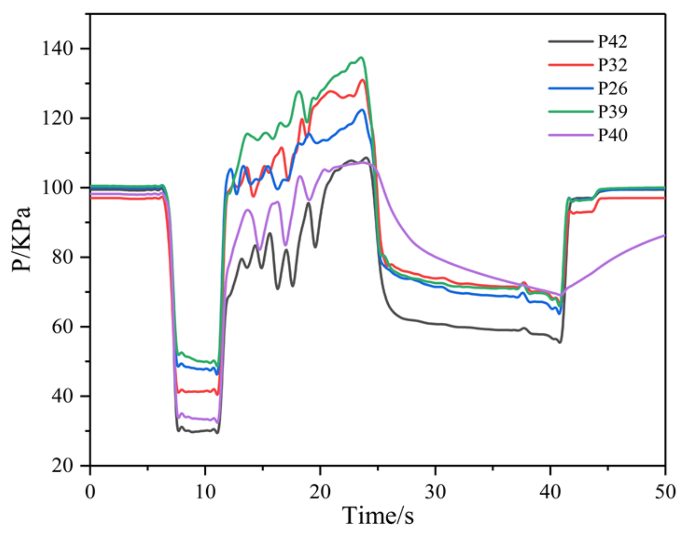
3.3. Working Characteristics of the SSRJ

The equivalence ratio can be calculated using:
φ = m ˙ air m ˙ fuel stoic m ˙ air m ˙ fuel
where m ˙ air and m ˙ fuel are the air and the fuel-rich gas mass flow rates, respectively; and the underscore stoic denotes the stoichiometric state. Figure 10 presents the bench thrust and equivalence ratio vs. time curves registered during the test. The equivalence is less than 1, indicating that the combustion was in an oxygen-rich state (the closer to 0, the more air it contains). Figure 10 also shows that thrust and equivalent ratio changed synchronously, i.e., both present an initial sudden and then gradual increase, indicating that there is almost no ignition delay when the fuel-rich gas is injected into the combustor and is mixed with supersonic air. In addition, the equivalence ratio gradually increased from 0.56 to 0.63, and the thrust gradually increased with the mass flow of fuel-rich gas, indicating that the test SSRJ configuration has the potential for a wide operating range.
Figure 11 shows the distribution and pressure taps naming for the tested SSRJ. Figure 12 shows the wall pressure curve on the center of the flow channel at different times during the test. It can be seen that, from the moment the air heater starts operating (~7.50 s), shock trains are established in the isolator to match the back pressure generated by the combustion in the combustor. After the gas generator is successfully ignited, the overall pressure distribution along the wall gradually increases with time. This is due to the slow increase of the fuel-rich gas mass flow and the combustion efficiency during the test, which leads to an increase in heat release along the combustor and in turn its wall pressure.
Note that the pressure of the combustor did not affect the pressure of the isolator, indicating that adding a step before the fuel-rich gas inlet is indeed beneficial to prevent the back pressure of the combustor from entering the inlet. This is because the steps provide extra space for heat-releasing and for adding mass to the fuel-rich gas. The highest pressure was always registered near the inlet of the fuel-rich gas, which is mainly caused by the shock wave produced by the fuel-rich gas jet entering the combustor. At the same time, it can also be caused by the high temperature gas of the fuel-rich gas entering the combustor, which quickly combusts with the air. In addition, note that the pressure in the area where the cavity is located remains high during the test, indicating that the cavity can form a certain high-pressure zone and play a role in stabilizing combustion.
Figure 13 shows the internal pressure of the cavity symmetrically arranged in the combustor, where (a) is the cavity at the first position along the flow direction and (b) is the cavity at the second position. It can be seen that the internal pressure of the symmetrically arranged cavity is basically the same, indicating that the flow field in the combustor achieves a symmetrical distribution. The change trend of the pressure curve at each position is consistent with the change of the thrust and gas generator curves, also showing that the test SSRJ can adapt to the changes of the fuel-rich gas mass flow.
The internal pressure of the cavity at the first position is significantly higher than that of the second position, while the former is basically the same, and the latter is significantly different. The above indicates that after the fuel-rich gas enters the combustor, it rapidly mixes and violently combusts with the supersonic air, near the cavity at the first position. On the other hand, the pressure in the cavity at the second position shows that the pressure in the middle of the cavity (P30/P37) is the highest, the pressure at the rear edge of the cavity (P31/P38) is the lowest, and the pressure at the front edge of the cavity (P29/P36) is in between these two. Our analysis suggests that the high pressure at the front edge of the cavity is caused by the low-velocity recirculation zone formed there. The entrainment effect of the recirculation zone promotes the combustion of the fuel-rich gas and completes the mixing and combustion with air in the cavity. As a result, the pressure is highest in the middle of the cavity (P30/P37). Although the trailing edge of the cavity has a blocking and pressurizing effect, these are reduced by ablation (see analysis below). In addition, the flow channel area increases, lowering the pressure in the cavity.
To further illustrate the role of the cavity, Figure 14 shows the variation of its internal pressure and the pressure of the mainstream at the same flow direction. It can be seen that the pressure change mechanism at each point is consistent with the evolution of the pressure in the gas generator. This indicates that the increase in pressure at each point is mainly caused by the increase in the mass flow of the fuel-rich gas, which also evidences that the fuel-rich gas that enters the cavity is effectively burned. At the same time, it can be seen that in the early stage of the test, the pressure inside the cavity was significantly higher than the mainstream pressure. As the test progressed, this pressure gap gradually decreased. In particular, during the last stage of the test, the internal pressure of the cavity at the second position was basically the same as the mainstream pressure. This demonstrates that the internal combustion state of the cavity is better than that at the center of the combustor during the beginning of the test, and that the cavity promotes the ignition of fuel-rich gas and air. In the last stage of the test, the mainstream of the combustor also establishes a stable combustion. At this point, the cavity promotes mixing and combustion and, at the same time, assumes the role of stable combustion. The above analysis shows that our cavity design is indeed helpful in reducing the ignition delay time of the fuel-rich gas, and improves combustion efficiency.
Figure 15 shows the structure of the cavity before and after the test. It can be seen that the bottom wall of the first cavity is ablated, while the bottom wall of the second cavity is complete. While the back edge of both cavities is ablated, the first cavity is more serious. This suggests that the heat release is concentrated around the first cavity, which is consistent with the analysis presented above. It should be emphasized that the heat generated at the first cavity is mainly produced by the combustion of the gas components in the fuel-rich gas. On the other hand, a larger number of particles are deposited in the second cavity compared to the first cavity. We speculate that this may be due to the large particles’ inertia and penetration depth, which causes them to collide in the flow channel, bounce back and then move to the wall before flowing into the second cavity.
Figure 16 shows the pressure changes of the five pressure measuring points arranged at the outlet of the combustor. It can be seen that the outlet pressure distribution during SSRJ operation is not uniform. In particular, there is low pressure at the wall and the center of the flow channel, and high-pressure in the area between these two. This is most obvious in the later stage of the test. Figure 16 also evidences that the combustor achieves symmetrical combustion of the fuel-rich gas, and that the combustion area is not close to the wall or in the center of the combustor. On the one hand, it can be seen that the thermal load on the wall of our combustor is relatively light, which is favorable to the long-term operation of the SSRJ. Moreover, Figure 16 shows that the fuel-rich gas in the combustor cannot diffuse to the center of the flow channel, and that the mixing between the fuel-rich gas and supersonic air needs to be enhanced.
Figure 17 depicts the flame at the outlet of the combustor. It can be seen that the flame is distributed symmetrically, which is consistent with our analysis of the pressure distribution at the outlet of the combustor. The outlet flame is mainly yellow, which indicates that the carbon particles at the outlet burn well, and the boron particles have no obvious combustion characteristics. In addition, a large number of luminous solid particles can be clearly observed in the outlet flame, indicating that the solid particles are not completely burned, and thus, the combustion efficiency of the particles is not very high.
Figure 18 shows a photo of the inner wall surface at the outlet of the combustor after the test. It can be clearly observed that a large number of condensed phase product are deposited on the inner wall surface. The deposition is evenly distributed on the wall surface, indicating that the particles have a greater penetration depth compared to the gaseous components in the fuel-rich gas, that they can collide and rebound within the combustor, and that are evenly distributed throughout the combustor. The particles deposition also shows that the particles combustion efficiency in the fuel-rich gas is indeed not high.

3.4. Performance of the Tested Solid Scramjet

The performance of the tested SSRJ is evaluated by the equivalent ratio, combustion efficiency, thrust gain specific impulse, total pressure recovery coefficient, and Mach number of combustor outlet. The combustion efficiency in a scramjet combustor is defined as [35]:
η Δ h = C p T t , exp e C p T t , exp in ( C p T t , the ) e ( C p T t , exp ) in
where the underscores e and in represent the inlet parameters of the isolator and the combustor outlet, respectively. The theoretical total outlet temperature and C p are obtained from the thermal calculation software CEA [34].
The velocity ( v e ) and Ma e of the combustor outlet are calculated from [35]:
F = m ˙ e v e + p e p a A e
Ma e = F p e p a A e γ e p e Ma e 1 / 2
where m ˙ e is the mass flow rate at the combustor outlet, p a is the environment pressure, F is the bench thrust, p e is the pressure at the combustor outlet measured by the pressure scanning valve, A e is the outlet area of the combustor, and γ is the specific heat ratio calculated by CEA.
The total pressure recovery coefficient δ is defined as [35]:
δ = p t , e p t , in
where p t , e and p t , in are the total pressure at the combustor outlet and the inlet of the isolator, respectively.
The total pressure p t , in at the combustor outlet is derived from [35]:
p t , e = p e 1 + γ e 1 2 Ma e 2 γ e γ e 1
where p t , in is estimated based on the method given in [35].
Using the above-described analysis method, we calculated the performance curve of the SSRJ during the test, see Figure 19. It can be seen that during the test, the change trend of each parameter is basically the same, and the performance of the SSRJ continuously increases up to the last stage, where it stabilizes. The Mach number at the outlet of the combustor decreased during the test from 1.76 to 1.20, indicating that the outlet was in a supersonic state. Due to the deposition of the gas generator throat and the change of the propellant combustion area, the equivalence ratio increased from 0.54 to 0.63. At the beginning of the test, the combustion efficiency was only 0.03, indicating the existence of an ignition delay of the fuel-rich gas. However, the fuel-rich gas and supersonic air quickly established combustion in a short time. The combustion efficiency gradually increased during the test, reaching a maximum of 0.42. We conclude that this is caused by the expansion of the combustion area from the cavity to the center of the combustor, which is also consistent with the operating characteristics of multi-cavity liquid scramjets.
Both the combustion efficiency and the total pressure recovery coefficient increased, the latter from 0.25 to 0.35. This is contrary to the results of previous studies, which suggest that the higher the combustion efficiency, the smaller the total pressure recovery coefficient. Through the analysis of Figure 12, it can be postulated that under the action of the shock trains in the isolator, the Mach number at the inlet of the combustor gradually decreases, thereby reducing the total pressure loss in the combustor. This is further supported by the gradual decrease of the Mach number at the outlet of the combustor during the test. The thrust augmentation specific impulse is determined by the combustion efficiency and the total pressure recovery coefficient, which rose from 252 to 418 s during the test.
The SSRJ configuration adopted in this work accomplished symmetrical combustion in the combustor, the fuel-rich gas mixed with supersonic air burned rapidly, and there was almost no ignition delay time. However, the maximum test combustion efficiency was only 0.42, which is far from meeting the needs of real engineering applications. Our analysis shows that in this test, the combustion efficiency of the gas phase components in the fuel-rich gas was close to 100%, while the combustion efficiency of the condensed phase particles was only about 20%. We showed that the cavity layout used in this work had a significant effect on the combustion efficiency of gas-phase combustibles, but it did not have a significant effect on condensed phase particles.
The performance of the SSRJ is limited by the low combustion efficiency of the particles in the fuel-rich gas. Further research is required to optimize the size, position, number, and other parameters of the cavity according to the different characteristics of the gas phase components and condensed phase particles in the fuel-rich mixture, to further improve the working performance of the SSRJ. In addition, there is current research about the formation enthalpy and dissociation characteristics of boron and related fuels [36,37]. These studies will help understand the combustion mechanism of boron and related compounds. How to promote the combustion of boron by influencing the combustion mechanism of boron will also be carried out in the following research.

4. Conclusions

In this paper, we used boron-based fuel-rich solid propellant as fuel to carry out the first ever direct-connect test of a solid scramjet with symmetrical structure. The test simulated a flight environment at Mach 5.6 and 25 km. After measuring pressure, thrust, mass flow, and other parameters, and analyzing the test results, we conclude:
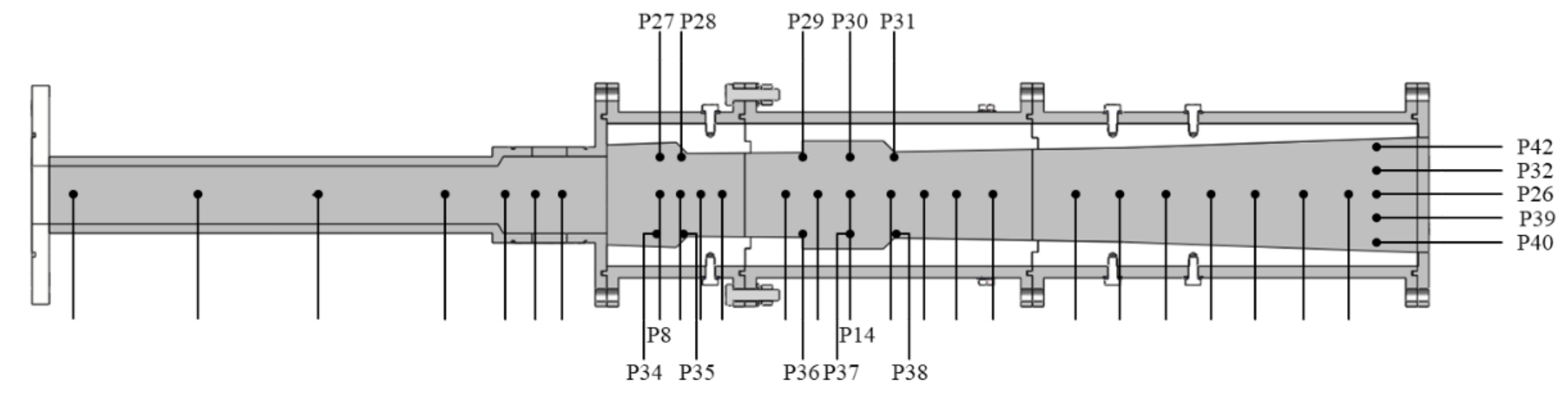
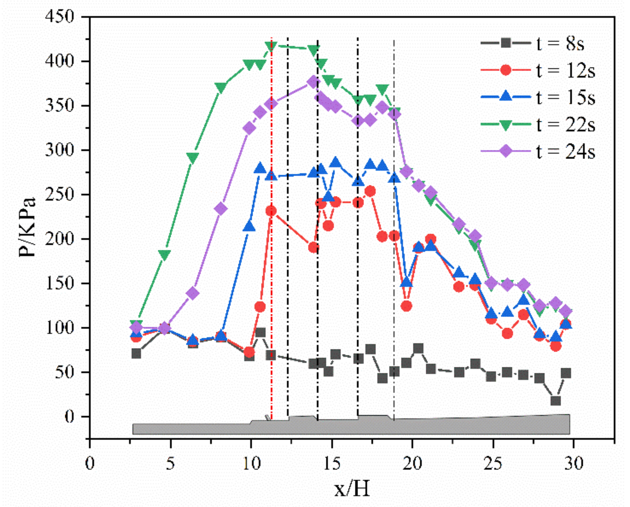
  • The solid scramjet with symmetrical structure used in the test can achieve a symmetrical distribution of the flow field in the combustor. The adopted supersonic, multi-cavity combustor enables the process that shifts the combustion state from the cavity to the center of the flow channel.
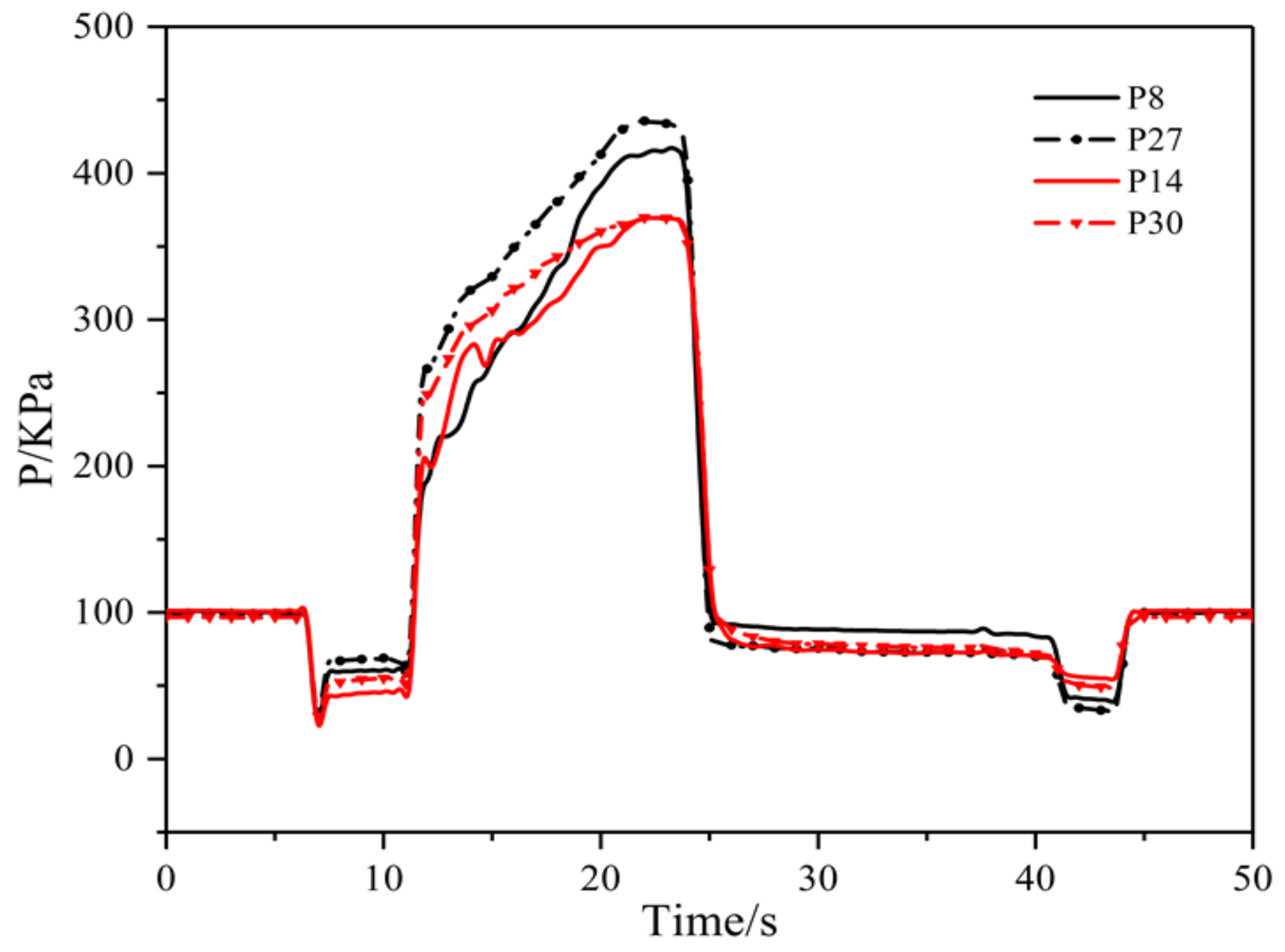
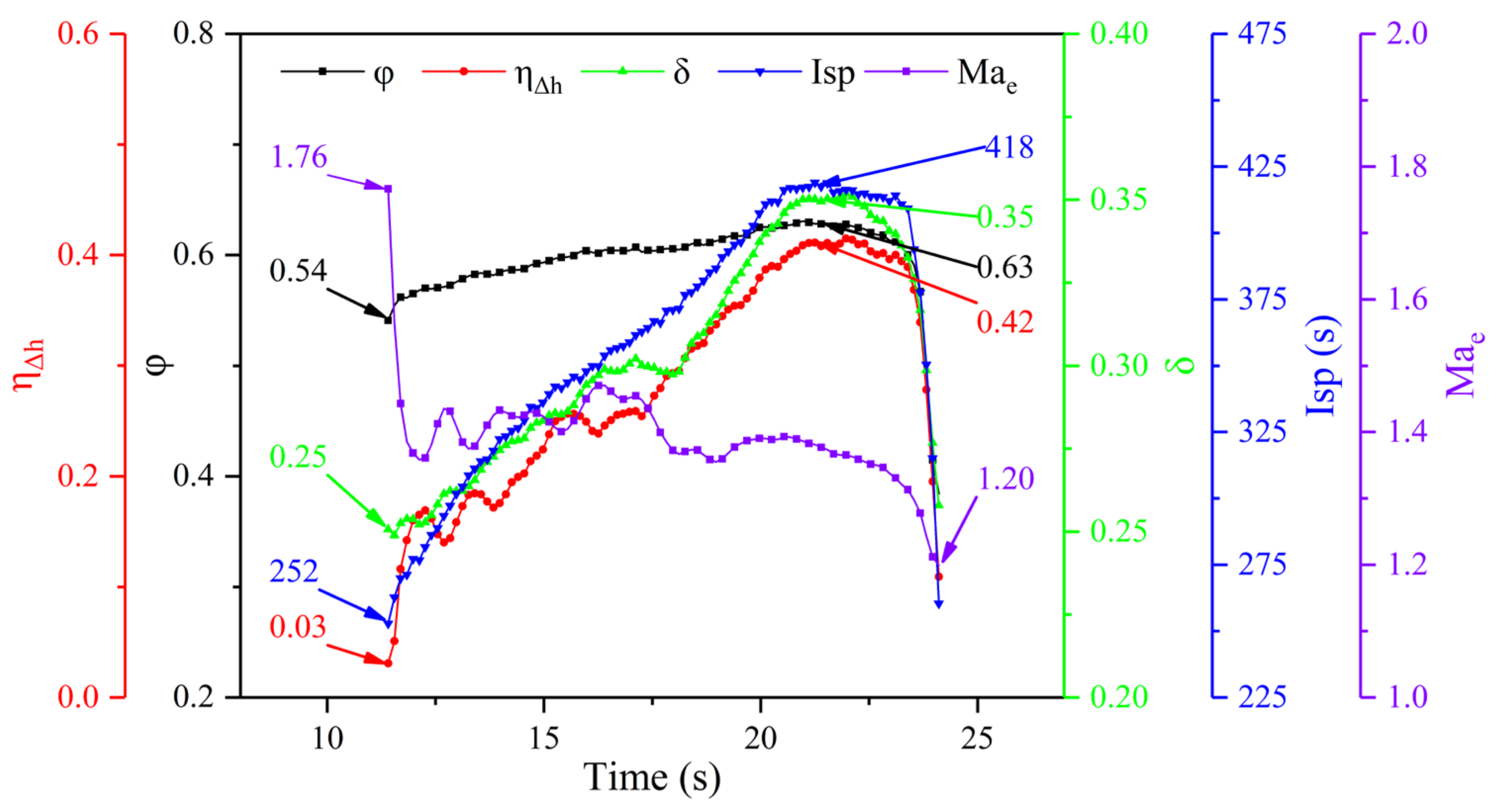
  • The fuel-rich gas mass flow continued to increase during the test due to the change of the propellant combustion area in the gas generator, and the deposition of the condensed phase products in the fuel-rich gas at the throat. The equivalence ratio gradually increased from 0.54 to 0.63.
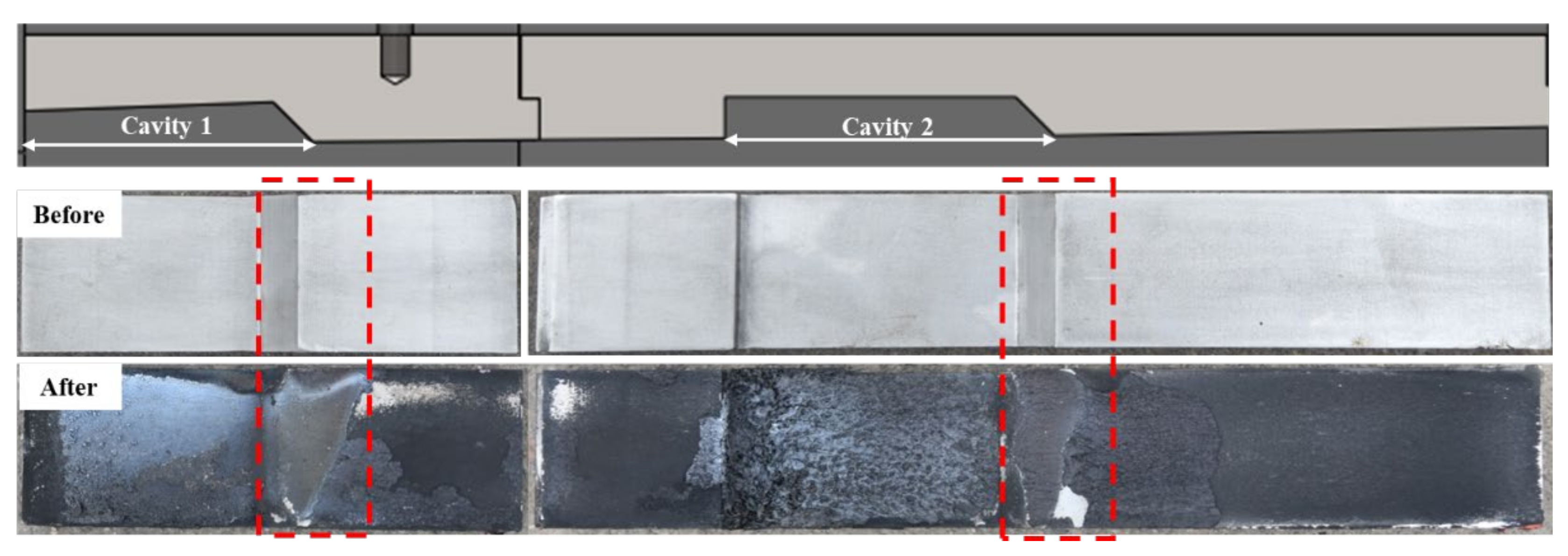
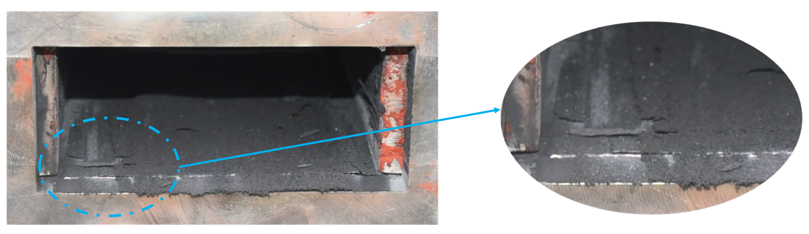
  • The cavity is helpful to reduce the ignition delay time of fuel-rich gas and improve the combustion efficiency; however, it mainly acts on the gas-phase combustible components. Particle deposition shows that the cavity configuration presented here does not have a significant promotion on the improvement of the combustion efficiency of condensed phase particles.
  • The maximum total combustion efficiency of the engine under test conditions was about 0.42. In this state, the combustor total pressure recovery coefficient and thrust gain specific impulse were 0.35 and 418 s, respectively. The shock trains in the isolator are beneficial to the recovery of the combustor total pressure.
Although the solid scramjet configuration adopted in this paper achieves stable operation, the maximum tested combustion efficiency is only 0.42, and the low particle combustion efficiency has become a key factor limiting engine performance. Our future work will combine engineering problems and use the different characteristics (motion, combustion, etc.) of the condensed phase particles and gas phase components in the supersonic combustor to optimize the structural parameters of the solid scramjet. At the same time, starting from the combustion mechanism of condensed phase particles, the particles are provided with an environment that is easy to react, so as to achieve the purpose of further improving the performance of the solid scramjet.

Author Contributions

Writing—original draft preparation, P.Y.; writing—review and editing, L.M.; visualization, C.L. and L.Z.; supervision, B.C.; project administration, Z.X.; funding acquisition, Y.F. All authors have read and agreed to the published version of the manuscript.

Funding

This research was funded by the Natural Science Foundation of Hunan Provincial (No. 2020JJ4665) and the National Natural Science Foundation of China (Grant No.52006240).

Institutional Review Board Statement

Not applicable.

Informed Consent Statement

Informed consent was obtained from all subjects involved in the study.

Data Availability Statement

The study did not report any data.

Acknowledgments

The authors appreciate the valuable comments on the paper by the reviewers. The first author thanks Jiamin Zhao for her company, sweetness and encouragement.

Conflicts of Interest

The authors declare no conflict of interest.

References

  1. Betelin, V.B.; Kushnirenko, A.G.; Smirnov, N.N.; Nikitin, V.F.; Tyurenkova, V.V.; Stamov, L.I. Numerical investigations of hybrid rocket engines. Acta Astronaut. 2018, 144, 363–370. [Google Scholar] [CrossRef]
  2. Choubey, G.; Yuvarajan, D.; Huang, W.; Shafee, A.; Pandey, K.M. Recent research progress on transverse injection technique for scramjet applications-a brief review. Int. J. Hydrogen Energy 2020, 45, 27806–27827. [Google Scholar] [CrossRef]
  3. Das, N.; Pandey, K.M.; Sharma, K.K. A brief review on the recent advancement in the field of jet engine—scramjet engine. Mater. Today Proc. 2021, 45, 6857–6863. [Google Scholar]
  4. Kushnirenko, A.G.; Stamov, L.I.; Tyurenkova, V.V.; Smirnova, M.N.; Mikhalchenko, E.V. Three-dimensional numerical modeling of a rocket engine with solid fuel. Acta Astronaut. 2021, 181, 544–551. [Google Scholar] [CrossRef]
  5. Ben-Arosh, R.; Natan, B.; Spiegler, E.; Gany, A. The reacting flowfield within a supersonic combustion solid fuel ramjet. In Proceedings of the 33rd Joint Propulsion Conference and Exhibit, Seattle, WA, USA, 6–9 July 1997. [Google Scholar]
  6. Chi, H.; Wei, Z.; Wang, L.; Li, B.; Wu, Z. Numerical Investigation of Self-Ignition Characteristics of Solid-Fuel Scramjet Combustor. J. Propuls. Power 2015, 31, 1019–1032. [Google Scholar] [CrossRef]
  7. He, Y.; Chen, Y.; Liu, D.; Liu, J.; Lai, M.; Liang, X. Research on Solid Rocket/Scramjet Combined Engine. In Proceedings of the 21st AIAA International Space Planes and Hypersonics Technologies Conference, Xiamen, China, 6–9 March 2017. [Google Scholar]
  8. Zhang, H.; Wang, N.; Wu, Z.; Fang, G.; Wei, Z. Preliminary investigation of paraffin-based fuel combustion in solid fuel scramjet. Acta Astronaut. 2020, 173, 119–130. [Google Scholar] [CrossRef]
  9. Witt, M.A. Investigation into the Feasibility of Using Solid Fuel Ramjets for High Supersonic/Low Hypersonic Tactical Missiles. Marster’s Thesis, Department of Astronautical Engineering, Nava Postgraduate School, Monterey, CA, USA, 1989. [Google Scholar]
  10. Angus, W.J. An investigation into the Performance Characteristics of a Solid Fuel Scramjet Propulsion Deviee. Marster’s Thesis, Department of Astronautical Engineering, Nava Postgraduate School, Monterey, CA, USA, 1991. [Google Scholar]
  11. Ben-Yakar, A.; Gany, A. Experimental study of a solid fuel scramjet. In Proceedings of the 30th AIAA/ASME/SAE/ASEE Joint Propulsion Conference, Indianapolis, IN, USA, 27–29 June 1994. [Google Scholar]
  12. Lv, Z.; Xia, Z.; Liu, B.; Liu, Y. Experimental and Numerical Investigation of a Solid-Fuel Rocket Scramjet Combustor. J. Propuls. Power 2016, 32, 273–278. [Google Scholar] [CrossRef]
  13. Liu, Y.; Gao, Y.; Chai, Z.; Dong, Z.; Hu, C.; Yu, X. Mixing and heat release characteristics in the combustor of solid-fuel rocket scramjet based on DES. Aerosp. Sci. Technol. 2019, 94, 105391. [Google Scholar] [CrossRef]
  14. Jung, W.; Baek, S.; Park, J.; Kwon, S. Combustion Characteristics of Ramjet Fuel Grains with Boron and Aluminum Additives. J. Propuls. Power 2018, 34, 1070–1079. [Google Scholar] [CrossRef]
  15. Jung, W.; Jung, S.; Kwon, T.; Park, J.; Kwon, S. Ignition Delay in Solid-Fuel Ramjet Combustor. J. Propuls. Power 2018, 34, 1519–1528. [Google Scholar] [CrossRef]
  16. Levin, V.A.; Lutsenko, N.A.; Salgansky, E.A.; Yanovskiy, L.S. A Model of Solid-Fuel Gasification in the Combined Charge of a Low-Temperature Gas Generator of a Flying Vehicle. Dokl. Phys. 2018, 63, 375–379. [Google Scholar] [CrossRef]
  17. Liu, L.-L.; He, G.-Q.; Wang, Y.-H. Effect of Oxidizer on the Combustion Performance of Boron-Based Fuel-Rich Propellant. J. Propuls. Power 2014, 30, 285–289. [Google Scholar] [CrossRef]
  18. Li, C.; Zhao, X.; Xia, Z.; Ma, L.; Chen, B. Influence of the vortex generator on the performance of solid rocket scramjet combustor. Acta Astronaut. 2019, 164, 174–183. [Google Scholar] [CrossRef]
  19. Bao, H.; Zhou, J.; Pan, Y. Effect of cavity configuration on kerosene spark ignition in a scramjet combustor at Ma 4.5 flight condition. Acta Astronaut. 2015, 117, 368–375. [Google Scholar] [CrossRef]
  20. Cai, Z.; Wang, T.; Sun, M. Review of cavity ignition in supersonic flows. Acta Astronaut. 2019, 165, 268–286. [Google Scholar] [CrossRef]
  21. Liu, Q.; Baccarella, D.; Landsberg, W.; Veeraragavan, A.; Lee, T. Cavity flameholding in an optical axisymmetric scramjet in Mach 4.5 flows. Proc. Combust. Inst. 2019, 37, 3733–3740. [Google Scholar] [CrossRef]
  22. Sun, M.B.; Gong, C.; Zhang, S.P.; Liang, J.H.; Liu, W.D.; Wang, Z.G. Spark ignition process in a scramjet combustor fueled by hydrogen and equipped with multi-cavities at Mach 4 flight condition. Exp. Therm. Fluid Sci. 2012, 43, 90–96. [Google Scholar] [CrossRef]
  23. Li, C.; Xia, Z.; Ma, L.; Zhao, X.; Chen, B. Numerical Study on the Solid Fuel Rocket Scramjet Combustor with Cavity. Energies 2019, 12, 1235. [Google Scholar] [CrossRef] [Green Version]
  24. Liu, J.; Wang, N.-F.; Wang, J.; Li, Z.-Y. Optimizing combustion performance in a solid rocket scramjet engine. Aerosp. Sci. Technol. 2020, 99, 105560. [Google Scholar] [CrossRef]
  25. Li-kun, M.; Chao-long, L.; Zhi-xun, X.; Xiang, Z. Experimental Investigation of Solid Rocket Scramjet Combustor with Cavity Flameholder. J. Propuls. Technol. 2021, 42, 319–326. [Google Scholar]
  26. Liu, Y.; Gao, Y.; Shi, L.; Chai, Z.; Yu, X. Preliminary experimental study on solid rocket fuel gas scramjet. Acta Astronaut. 2018, 153, 146–153. [Google Scholar]
  27. Yonggang, G.; Yang, L.; Zexin, C.; Xiaocong, L.; Chunbo, H.; Xiaojing, Y. Influence of lobe geometry on mixing and heat release characteristics of solid fuel rocket scramjet combustor. Acta Astronaut. 2019, 164, 212–229. [Google Scholar] [CrossRef]
  28. Li, C.; Xia, Z.; Ma, L.; Zhao, X.; Chen, B. Experimental and numerical study of solid rocket scramjet combustor equipped with combined cavity and strut device. Acta Astronaut. 2019, 162, 145–154. [Google Scholar] [CrossRef]
  29. Yang, P.; Xia, Z.; Ma, L.; Chen, B.; Feng, Y.; Zhang, J. Experimental study on the influence of the injection structure on solid scramjet performance. Acta Astronaut. 2021, 188, 229–238. [Google Scholar] [CrossRef]
  30. Zhao, X.; Xia, Z.; Ma, L.; Li, C.; Fang, C.; Natan, B.; Gany, A. Research progress on solid-fueled Scramjet. Chin. J. Aeronaut. 2021. [Google Scholar] [CrossRef]
  31. Choubey, G.; Devarajan, Y.; Huang, W.; Mehar, K.; Tiwari, M.; Pandey, K.M. Recent advances in cavity-based scramjet engine- a brief review. Int. J. Hydrogen Energy 2019, 44, 13895–13909. [Google Scholar] [CrossRef]
  32. Collatz, M.; Gruber, M.; Olmstead, D.; Branam, R.; Lin, K.-C.; Tam, C.-J. Dual Cavity Scramjet Operability and Performance Study. In Proceedings of the 45th AIAA/ASME/SAE/ASEE Joint Propulsion Conference & Exhibit, Denver, CO, USA, 2–5 August 2009. [Google Scholar]
  33. Li, X.P.; Liu, W.D.; Yang, L.C.; An, B.; Pan, Y.; Zhu, J.J. Experimental Investigation on Fuel Distribution in a Scramjet Combustor with Dual Cavity. J. Propuls. Power 2017, 34, 552–556. [Google Scholar] [CrossRef]
  34. Gordon, S.; McBride, B.J. Computer Program for Calculation of Complex Chemical Equilibrium Compositions and Applications. Part 1: Analysis; NASA Center for Aerospace Information (CASI): Linthicum, MD, USA, 1994.
  35. Li, C.; Xia, Z.; Ma, L.; Zhao, X.; Chen, B.; Yang, P. Performance evaluation for scramjet based on ground direct-connected test: A method investigation. Aerosp. Sci. Technol. 2021, 117, 106895. [Google Scholar] [CrossRef]
  36. Kumar, R.; Karkamkar, A.; Bowden, M.; Autrey, T. Solid-state hydrogen rich boron–nitrogen compounds for energy storage. Chem. Soc. Rev. 2019, 48, 5350–5380. [Google Scholar] [CrossRef]
  37. Wong, B.M.; Lacina, D.; Nielsen, I.M.B.; Graetz, J.; Allendorf, M.D. Thermochemistry of Alane Complexes for Hydrogen Storage: A Theoretical and Experimental Investigation. J. Phys. Chem. C 2011, 115, 7778–7786. [Google Scholar] [CrossRef]
Figure 1. Schematic of a solid scramjet.
Energies 14 05589 g001
Figure 2. Schematic of the solid scramjet proposed by Xia et al.
Energies 14 05589 g002
Figure 3. Schematic of the direct-connect test experiment platform.
Energies 14 05589 g003
Figure 4. Schematic of the solid scramjet structure, including dimensions.
Energies 14 05589 g004
Figure 5. (a) Main energy-containing components in the fuel-rich gas; (b) main energy proportions in the fuel-rich gas.
Energies 14 05589 g005
Figure 6. Schemes follow the same formatting.
Energies 14 05589 g006
Figure 7. Evolution of pressure of in the gas generator during the test.
Energies 14 05589 g007
Figure 8. Schematic diagram of the propellant burning surface retreat during the test.
Energies 14 05589 g008
Figure 9. Topography of the throat changes before and after the test.
Energies 14 05589 g009
Figure 10. Evolution of the equivalence ratio and thrust during the test.
Energies 14 05589 g010
Figure 11. Distribution and naming of pressure taps along the tested SSRJ.
Energies 14 05589 g011
Figure 12. Pressure distribution along the wall surface of the SSRJ at different times.
Energies 14 05589 g012
Figure 13. (a) Internal pressure of the cavity at the first position symmetrically arranged in the combustor; (b) internal pressure of the cavity at the second position symmetrically arranged in the combustor.
Energies 14 05589 g013
Figure 14. Internal pressure of the cavity and pressure of the mainstream at the same flow direction vs. time.
Energies 14 05589 g014
Figure 15. Comparison of the cavity before and after the test.
Energies 14 05589 g015
Figure 16. Pressure distribution at the outlet of the combustor.
Energies 14 05589 g016
Figure 17. Flame at the outlet of the combustor.
Energies 14 05589 g017
Figure 18. Inner wall surface at the outlet of the combustor after the test.
Energies 14 05589 g018
Figure 19. Evolution of the solid scramjet performance parameters during the test.
Energies 14 05589 g019
Table 1. Time sequence of the experiment.
Time/sInstruction
0.00Start
7.50Air heater ignition
11.10Gas generator ignition
43.05Air valve off
50.00End
Publisher’s Note: MDPI stays neutral with regard to jurisdictional claims in published maps and institutional affiliations.

