1. Introduction
Recent trends in aircraft development and related research and development (R&D) programs show the increasing role and importance of electrically powered onboard equipment that was traditionally powered by hydraulic or pneumatic systems. This has resulted in an increased onboard power generation capacity, exceeding 1 MW in civil aircraft programs in some cases. The primary motivation behind this transition to the electrification of the aviation sector is to reduce pollution while increasing the reliability and maintainability of the affected systems [
1]. The trend is clearly a move toward a more-electric aircraft (MEA) or even an eventual all-electric Aircraft.
Looking ahead, further and even more radical increases in airborne energy usage above the few MW level are expected from the partial or the even full electrification of primary or propulsive power within the next generation of MEA technology (hybrid-electric and full-electric). The current vision is that the potential for weight saving and efficiency improvement of onboard EPS and MEA can only be unlocked if we consider the triage of the weight–efficiency–power level and their interactions. As an essential brick of this integrated approach, efficient E2-EM (Enhanced Electrical Energy Management) strategies shall be implemented. E2-EM is defined as the advanced smart control of aircraft electrical loads and power sources that aims at obtaining a reduction of generator weight and size, while also increasing reliability. The state of the art [
2] is represented in
Figure 1a for a generic aircraft, where the electrical load management (ELM) is based on the complete switch-off of non-essential loads (e.g., galley, IFE, cabin lights). The disconnection order is decided by the pilot on smaller a/c or is automatically performed by control units on larger a/c.
E2-EM overcomes this fundamental limit of simple ELM and instead considers an advanced smart control of aircraft electrical loads and power sources rather than just ON/OFF actions. This is achieved by the following two features:
- (1)
A supervisor is introduced as the key means to send and receive specific messages on a communication network;
- (2)
Power conversion equipment is implemented in the advanced control algorithm to implement the E2-EM functions.
A general reference scheme is shown in
Figure 1b. The green-dotted line may represent any of the currently available onboard communication networks, e.g., AFDX, CAN, ARINC. Moreover, the introduction of secondary energy storage sources (e.g., batteries, supercapacitors, fuel cells) provides an extra degree of freedom and aligns the E2-EM to the most recent advancement in the field of hybrid/all electric aircraft, where the role of any component other than the main generator source(s) is a decisive factor.
The “energy management” concept was already exploited in the numerous initiatives taken through the European Commission, such as the I-PRIMES [
3], MOET [
4], and EPOCAL [
5] projects. This paper extends these results by proposing E2-EM as a new integrated approach, and it is based on the research work being conducted within the ENIGMA Clean Sky 2 project. The aim of the ENIGMA project is to design, develop, manufacture, test, and integrate an innovative CSS embedding E2-EM strategy into the EPGDS of Leonardo Aircraft Iron Bird ground demonstrator.
According to the literature, energy management schemes mainly involve the efficient management of energy storage devices [
6,
7,
8,
9,
10,
11] and the management of loads, including priority-based load shedding [
2,
12,
13]. Furthermore, the idea of extending the energy storage and load management techniques to eliminate the overload capabilities of a generator has been considered by researchers and engineers due to its obvious operational and environmental benefits and the inclusion techniques to manage overload through generators [
14], batteries [
6], supercapacitors, and power distribution to loads [
14]. However, energy management strategies involving the elimination of the overload capability of generators has not been fully exploited in the literature.
The work conducted within the ENIGMA project exploits the “5 s and 5 min” overload capability of the generator. The energy management strategy is designed to ensure that overloads are cleared within 5 s. Since the 5 s capability is ensured, the 5 min capability is no longer required. This enables the overload capability requirement for the main generator sizing to be removed, leading to a substantial reduction in the mass of generators, which is estimated to be up to 15% for existing airborne class W generators. This can lead to a significant contribution in achieving more efficient, greener aviation. In addition, the developed ENIGMA CSS will be interfaced with the lower-level controllers of the smart grid network (SGN), the energy storage and regeneration system (ESRS), and the programmable load bank 1 secondary distribution board (PLB1 SDU) of the Iron Bird EPGDS to provide the optimal management and the sharing of available on-board electric power during overloading and failure conditions. The SGN, ESRS, and the PLB1 SDU are currently being developed within the Regional Integrated Aircraft Demonstration Platform projects ASPIRE, ESTEEM, and IDEN respectively.
The ENIGMA CSS embeds E2-EM control logic based on the aforementioned E2-EM strategies. The overall CSS development has been conducted by employing a formal mathematical approach based on the formalisation of the E2-EM as an algorithm operating in real time under safety and reliability rules, including the optimisation mathematics at its core. The developed CSS will also be capable of expansion in order to include interfaces with other lower-level subsystems to be developed by future regional projects.
Prior to the integration of the ENIGMA CSS in the Leonardo aircraft ground demonstrator, the CSS needs to undergo a number of testing phases comprised of model-in-the-loop (MIL) and then hardware-in-the-loop tests. This paper focusses on MIL testing. For this purpose, a set of simulation models of the ENIGMA CSS, the Iron Bird EPGDS including the SGN, ESRS, and PLB1 SDU, have been developed at the functional level within the software environment MATLAB/Simulink. This paper aims to verify and validate the performance of the ENIGMA CSS through MIL demonstration.
This paper is organised in six sections. After this introductory section, the energy management strategy that will be adopted for the ENIGMA CSS is detailed in
Section 2.
Section 3 describes the Iron Bird EPGDS and its subsystems, while
Section 4 provides an in-depth explanation of the E2-EM algorithms and logic to be implemented in the ENIGMA CSS.
Section 5 gives the MIL demonstration of the E2-EM control strategy through the presented test results. Finally, the paper is concluded with the mention of future works.
2. ENIGMA Energy Management Strategy
As mentioned in the Introduction section, the aerospace industry is moving towards the MEA paradigm from different perspectives. One of the beaten paths involves the adoption of more sophisticated energy management systems (EMSs) to enable the smart and optimized management of onboard available power and to counteract it with appropriate actions in the presence of possible generator failures and overload conditions. The objective of the ENIGMA CSS is to optimally coordinate the sharing of available onboard power during generator overloads and failure conditions. This objective is achieved by the ENIGMA CSS controlling the power consumption and the generation of the EPGDS subsystems that include the SGN, ESRS, and PLB1, as will be detailed in the next section. ENIGMA action, supported by the flexibility provided by each subsystem, controls and maintains the power output of the generators below the maximum rated power in the event of overload and/or failure conditions.
Aircraft generators are generally sized according to the 5-min, 5-s rule. Conventionally, the 5-min capability means that the generator can be overloaded for 5 min with a power of up to 150% of its nominal rated power, and the 5-s capability implies that the generator can be overloaded for 5 s with a power of up to 200% of its nominal rated power. An overload condition may occur as the result of an extra load being connected to the aircraft EPGDS. The time at which an overload condition appears and the amount of power it requires are unknown a priori. The objective of the CSS described in this work is to counteract the presence of unpredicted overload conditions in a smart and optimized way. In particular, the main requirement that the CSS has to satisfy is to clear the generator overload within 5 s from its detection, with the implication that the 5 min capability can be removed from the generator design, thus reducing the weight and size of the generator.
Figure 2 is the graphical representation of the generator overload conditions that can occur in the EPGDS and that are used to define the ENIGMA CSS strategy. It uses the following key quantities:
(W) represents the threshold above which the CSS starts to take action in coordination with the different subsystems to clear the overload. If the generator power exceeds this threshold, an overload condition is detected;
(W) is the maximum rated power that a generator can sustain. This value generally reflects the generator’s specifications;
(t) (W) represents the instantaneous actual power of the generator at time (t).
In general, the condition holds. If an aircraft is equipped with multiple generators, the value of is generally the same for all of the generators.
The ENIGM CSS monitors three main conditions: A, B and C, as depicted in
Figure 2, in order to take appropriate actions:
Condition A: if the threshold power , and exceeds , ENIGMA CSS triggers preliminary corrective actions to lower the generator power to be less than within approximately 5 s. These preliminary actions do not entail stringent actions such as load shedding and aim to reduce the probability of the generator overloading;
Condition B: By setting the threshold power equal to (and not greater than) , as soon as exceeds , ENIGMA CSS must initiate stringent actions to lower the generator power below within 5 s. These actions may include an additional set of measures such as load shedding;
Condition C: When is less than and is therefore also less than , ENIGMA CSS will not initiate any action and will let the local controllers of the subsystems perform their energy management roles. The CSS only works when there is an overload condition. If no overload is taking place—and if suitable conditions take place—the CSS can set the supercapacitor to recharge.
The threshold is used as a hysteresis to activate the CSS earlier before the maximum generator limit is reached, where the overloading of the generator happens. Condition B is obviously a subcase of Condition A when .
Based on this high-level description, three main operating stages of the ENIGMA CSS can be defined:
Normal stage: the EPGDS is not subject to overload conditions and no CSS intervention is required. The CSS does not send any control actions to the SGN, ESRS, and PLB, and the supercapacitor of the ESRS is set to the recharge mode;
Overload management stage: ENIGMA CSS detects an overload condition and is activated. The CSS manages the overload by coordinating the power consumption and the generation of the SGN and the ESRS, and the PLB ensures that the generators operate in safe conditions. The three subsystems are invoked in a specific order. The stage concludes when the overload condition disappears;
Recovery stage: In this stage, which happens after the overload management stage, ENIGMA CSS recovers the SGN, ESRS, and PLB1 SDU subsystems and re-establishes them to their normal conditions, i.e., the conditions they were in before the overload occurred. The three subsystems are recovered in the opposite order to the one adopted in the overload management stage.
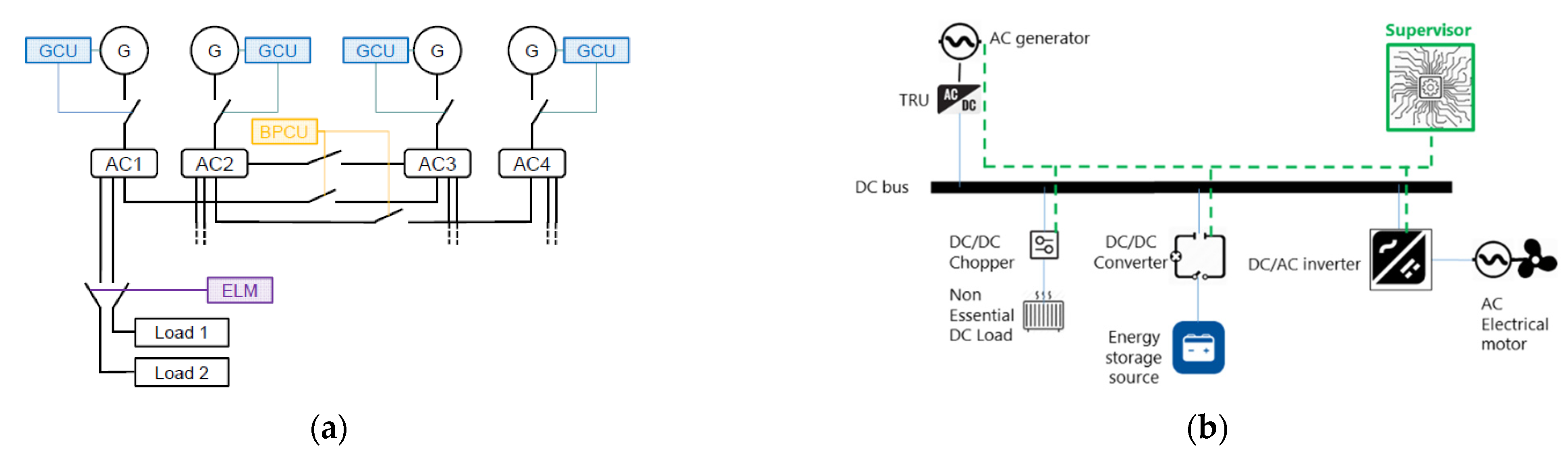
3. Iron Bird EPGDS Architecture
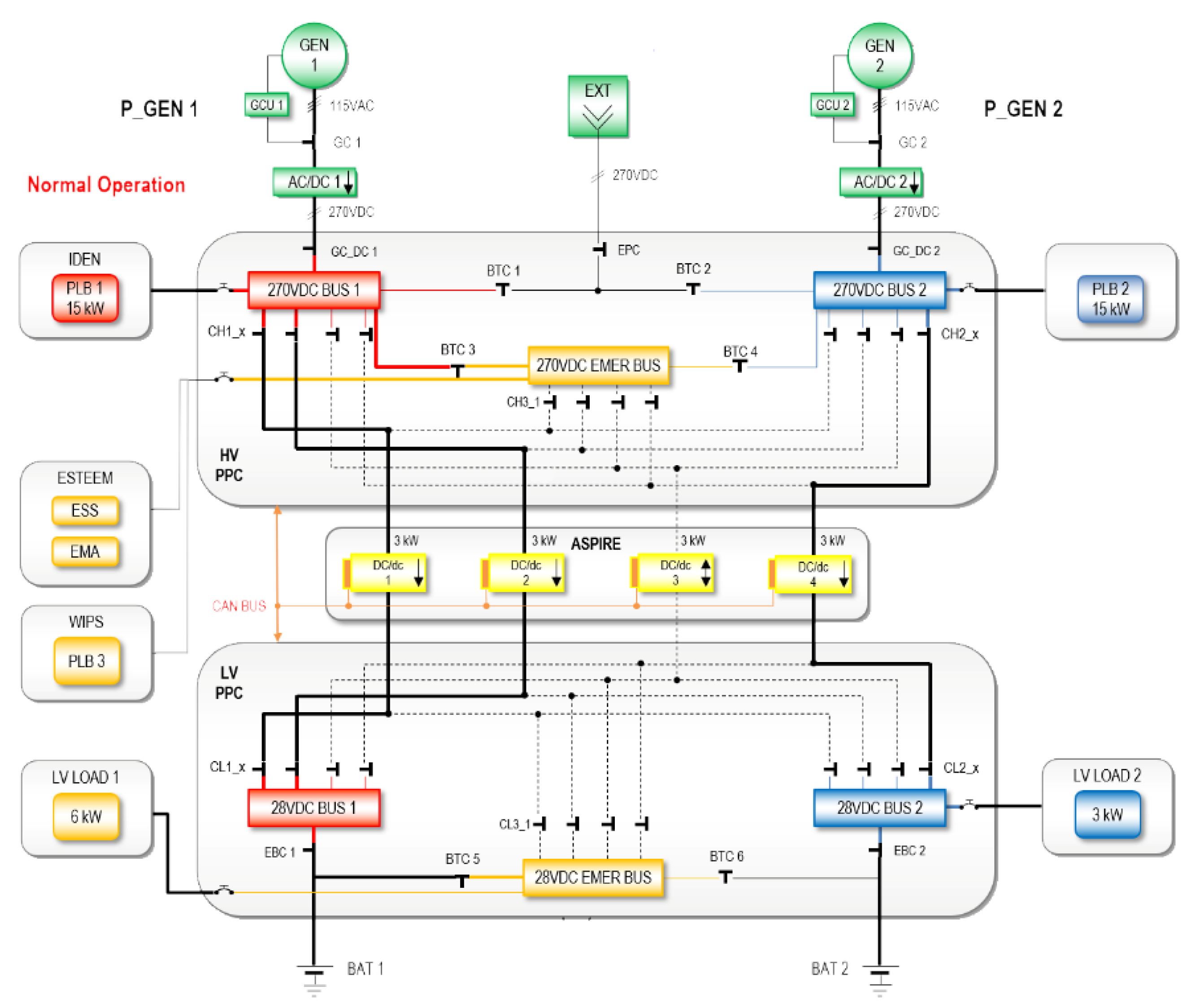
This section presents the Iron Bird EPGDS under study, as depicted in
Figure 3, and its subsystems, namely the generators, primary power centers (PPCs), SGN(ASPIRE), ESRS(ESTEEM), and PLB1 SDU (IDEN). It describes how the ENIGMA CSS controller integrates within the EPGDS and how it interfaces with these subsystems. The functional simulation model of the EPGDS, as shown in
Figure 3, has been developed in MATLAB Simulink 2017b. The simulation model will be used to verify the functionality and validity of the ENIGMA CSS algorithm, as will be shown in a later section.
3.1. The Generators, Batteries and PPCs
A total of two 21 kW primary generators (Gen 1, Gen 2) each interfaced with AC/DC power electronic converters (PEC) generate 270V controlled HVDC power to the high-voltage PPC (HV PPC). An external ground power source (EXT) may also be used to power the EPGCS. The batteries (BAT 1, BAT 2) supply power to the low-voltage PPC (LVPPC). The battery is modelled using the first order frequency response of a 28 V/44 Ah NiCd battery. The HV PPC and the LV PPC simulation models emulate the functional behaviour of the physical HV PPC and the LV PPC devices, respectively. They open and close solid the state power controllers (SSPCs) and relays according to external activation signals. The models also provide current and voltage measurements as well as the activation state of the different SSPCs and relays.
3.2. Smart Grid Network (SGN)
The EPGDS consists of a decentralized, modular and flexible smart grid network. The SGN, when coupled with E2-EM functionalities, aims to achieve substantial improvements in system efficiency, safety, power quality, and eco-friendliness compared to existing solutions. The Clean Sky project ASPIRE [
15] developed DC/DC dual active bridge bidirectional converter units for the four cells of the SGN. It also developed and implemented advanced EM control approaches to optimally manage the distribution of power among the four cells and for selecting the operating mode (step-up or step-down mode) for the individual cells. When interfaced with the ENIGMA CSS controller, the SGN can assist in reducing or even deleting the overload capabilities of the main generators, thus saving weight for electrical machine integration.
The normal operating mode of the SGN cells is the step-down mode used to charge the batteries and to feed the LV loads. The reversal or step-up mode of the cells is only used in case of emergency; it is enabled when one generator is in fault, the healthy generator is in overload, and at least one HV load has a priority greater than one or both LV busbars. During the reversal mode, one or both batteries are discharged. The SGN cannot manage the loads connected to the discharging battery. The reversal mode is allowed as long as one or both batteries have a state of charge (SOC) greater than the minimum allowed SOC.
The SGN can also work with a reduced number of cells in case one or more cells are in fault with some loads underpowered or if the required power is greater than the available power.
3.3. Energy Storage and Regenerative System (ESRS)
The ESRS in the Iron Bird EPGCS, developed within the Clean Sky project ESTEEM [
16], consists of a regenerative electro-mechanical actuator (EMA) and an embedded supercapacitor (SC) energy storage device. The smart energy management developed for the EMA contributes to two key capabilities of the ESRS. First, it smooths the generator power profile when a sudden variation in the EMA current demand occurs. It also provides power to the grid in the case of generator overload, which is in coordination with the ENIGMA CSS controller.
3.4. Programmable Load Bank 1 Secondary Distribution (PLB1 SDU)
The PLB1 SDU is used to interface the 270 V DC-bus with the PLB 1, as depicted in
Figure 3. The PLB1 SDU is equipped with a DC/DC controller to control and manage the power to the PLB1. Of note is that the EPGDS comprises two other PLBs, namely PLB 2 and PLB 3. In contrast to PLB1, the loads PLB 2 and PLB3 are not controlled independently by an SDU DC/DC converter but are connected directly to the high voltage (HV) bus, as depicted in
Figure 3.
The PLB 1, rated at 270 V/15 kW, is connected to HV Bus 1 through a SDU. The PLB 2, rated at 270 V/15 kW, is connected to HV Bus 2 while the PLB3, rated at 270 V/8 kW, is connected to the HV Emergency Bus. The PLB1 SDU and the corresponding DC/DC converter are being developed under the Clean Sky project IDEN [
17]. The key capability of the PLB1 SDU is to achieve load chopping and load shedding for energy management purposes. During load chopping, the power supplied to the PLB 1 may be reduced from 15 kW down to 13 kW by reducing the voltage from 270 V to 250 V by means of a DC/DC PEC located within the PLB1 SDU. Similarly, the power to the PLB1 may be increased from 13 kW up to 15 kW by increasing the voltage.
3.5. ENIGMA CSS within the EPGCS
The subsystems of the EPGCS, namely the SGN, PLB1 SDU, and ESRS, are smart systems with their own local controllers. The ENIGMA high-level supervisory controller sends appropriate control signals in the form of power set points to the local controllers of the aforementioned subsystems to achieve its EM objective. This will be further elaborated upon in the next section.
3.6. Iron Bird–CSS Communication Protocol and ENIGMA Firmware
The Iron Bird uses a CAN bus for communication between the different elements of the system, including ENIGMA CSS, SGN, ESRS, and PLB1 SDU. A number of items for monitoring information are exchanged on the CAN bus, such as generator current and energy storage states of charge. CAN is a multi-master (peer-to-peer) communication system where all systems broadcast messages regarding their status or decisions, and each system chooses the messages that are relevant to its operation. Each message has a priority. If messages collide, the higher priority message will be re-sent, while the lower priority message will be slightly delayed before being re-sent.
The ENIGMA CSS will utilise information about the current power requirements on the CAN bus, including information regarding any generator overloads and the status of the SGN, ESRS, and PLB1 SDU to make real-time decisions for the EPGCS. It will then broadcast these decisions as supervisory commands to the relevant subsystems. ENIGMA has to solve real-time optimization problems while simultaneously receiving and transmitting CAN messages and processing this information in the background.
Model based design (MBD) has been used in the implementation of the ENIGMA CSS; it was vital that the ENIGMA CSS be able to interface with software tools such as MATLAB/Simulink for this purpose. For the consideration of software and hardware implementation requirements, such as fixed-point and timing behavior, automatic code generation has been used for embedded deployment and to create test benches for system verification. This saves time and avoids the introduction of manually coded errors. The use of MBD and automated code generation means that it is possible to target different processors and architectures without re-writing code as well as to profile and verify embedded code on microcontrollers.
4. E2-EM Algorithm and Logics
This section describes the E2-EM algorithm and logic. An optimization-based approach has been selected for the mathematical formulation of the energy management control algorithm to account for the individual system performance and constraints, the global energy system performance and the overall system power balance. To formulate the optimization problem, it is important to have online and offline knowledge about the EPGDS and its subsystems, to identify the feasibility constraints, and to define the intended objective function. Moreover, we consider the constraints induced by the bounds for the set points and system variables and the constraints due to the dynamic behaviour of the storage and power actuation. The mathematical formulation is important for the scalability of the solution. With a well-formulated optimization problem, future subsystems can be added, and new rules can be derived based on the established procedures.
This section first describes the mathematical models and constraints for the SGN, ESRS, and PLB1 SDU subsystems. It then explains the CSS optimization formulation and finally describes the E2-EM logic and heuristics.
4.1. System Models and Constraints
This subsection describes the mathematical models of each of the controllable subsystems SGN, ESRS, and PLB1 SDU.
4.1.1. Energy Storage and Regeneration System
As described in the earlier section, the ESRS consists of an EMA and a supercapacitor. During an overload, ENIGMA CSS sends a signal to the ESRS, and the supercapacitor provides power to the EPGDS. When the overload is cleared, ENIGMA CSS sends another signal to the ESRS to recover and return to the nominal condition (i.e., to the state prior to the overload).
The dynamic model of the supercapacitor state of charge (SOC) at time
can be modelled as
where
(s) is the current discrete time instant (which is a multiple of the sampling time
),
(W) represents the instant power reference signal sent by ENIGMA CSS to the ESRS,
(J) is the energy capacity of the supercapacitor, and
(%) represents the SOC at time (
). The
and
are limited by their physical characteristics, so the following constraints are added:
where
and
are the minimum and maximum of the
, respectively, and
and
are the minimum and maximum values of
, respectively. The convention considered in this work is that when
, the supercapacitor yields power, i.e., discharges, and when
, the supercapacitor absorbs power, i.e., charges.
In condition of a fault (when
as explained below), the set point
; thus, Equation (3) can be written as
where
is a binary signal sent to ENIGMA CSS by the ESRS that represents the health state of the module, i.e., whether the ESRS is faulty or not (0 = fault, 1 = nominal state). If we replace Equations (1) in (2):
An additional signal state of device that describes failure conditions of the ESRS is introduced. It is a code that provides information about the status of the ESRS. The value of is “0” when the ESRS is functioning properly, “1” during an over voltage, “2” during an under voltage, “3” during high temperature condition, and “4” during a converter failure.
Remark 1. The supercapacitor may be recharged by setting . The recharging can be enabled by ENIGMA CSS if two conditions are met:
- i.
No overload is taking place;
- ii.
.
where (W) represents a design parameter (safety margin) of the ESRS. The second condition is used as safety constraint to ensure that the supercapacitor charging does not start close to since this could cause the generator power to exceed this maximum and could cause the system to overload again. When the CSS is operating in the overload management stage, no recharge can take place.
4.1.2. Programmable Load Bank1 Secondary Distribution Board
During an overload, the ENIGMA CSS sends a power set point
to the PLB1 SDU. Through voltage chopping action, the PLB1 SDU may reduce its actual power consumption by a value equal to
. Due to limitations inherent in the PLB1 SDU controller, the power set points are bounded between a minimum value
and a maximum value
; hence,
. Considering the functional state of the PLB1 SDU, the aforementioned equation can be rewritten as
where
is a binary signal sent to ENIGMA CSS by the PLB1 SDU that represents the state of the PLB (0 = faulty state, 1 = normal state).
4.1.3. Smart Grid Network
The ENIGMA CSS sends a power reference signal
to the SGN to activate and resolve an overload in coordination with the other two subsystems (PLB1 SDU and ESRS) during an overload condition. The SGN can thus be called to provide additional support to reduce an EPGDS overload condition. To achieve this, the SGN locally controls and actuates the DC/DC converters such that the generator’s power is maintained under the overload threshold. Similar to the ESRS and PLB1 SDU subsystems, the SGN communicates its fault condition through the use of a binary signal
to the ENIGMA CSS. The value of
can be either “0” when the SGN is operating normally or “1” when the SGN has a fault. The power reference signal
, which has a minimum value of zero and a maximum value
, can be expressed in terms of
as
The signal sent by the ENIGMA CSS to the SGN corresponds to a power reference value. The SGN controller algorithm is coded such that it triggers appropriate actions for the SGN that is connected to the batteries to provide the necessary power such that the generator power does not exceed that power reference level. In the event that the ENIGMA CSS either does not require the SGN to support the overload clearing or needs to re-establish the SGN back to its normal state after an overload, it sends a signal with the high value “255” to the SGN.
4.2. CSS Optimization Formulation
The previous sections defined the mathematical models and feasibility constraints for the power resources that the CSS needs to monitor and coordinate. The objective function of the CSS optimization formulation can now be defined. The E2-EM has to maintain the power balance in the EPGDS in addition to resolving the overload. This can be interpreted as balancing the difference between the total generated power of the
generators
and the overload threshold value
, i.e.,
. The total power of the
generators can be given as
where
is power of the ith generator, and
is a binary status value sent to ENIGMA CSS by the generators representing the availability of the ith generator and is assigned “0” if the generator is faulty or as “1” if the generator is healthy. Since the EPGDS of the aircraft under study is equipped with two generators
, the power balance of the system is given by
where
, and
are the ENIGMA CSS power set points to the SGN, ESRS, and PLB1 SDU subsystems, respectively. Equation (9) states that the difference between the generated power and the overload threshold value can be balanced by using extra power from the SGN, ERSN, and PLB subsystems.
Before proceeding to the CSS optimisation formulation, it is important to introduce the quantity
, which will be used for the algorithm formulation:
The new quantity is used to ensure that the ESRS power constraint (4) holds only when the ESRS is in healthy condition, i.e., when
or
(shown in (11) below). Since Equation (9) must be satisfied at all times, we define the ENIGMA CSS optimization problem OP as:
Which is subject to ((5), (6), and (7)):
For the optimization, , , and are considered as the optimization variables while , , , , , , , and are known parameter values provided offline, and and are the online measurements made available from ESRS and PLB1 SDU, respectively, at each time instant . The CSS OP, as shown in (10) and (11), is a mixed-integer linear programming (MILP) and can be solved using state-of-the-art MILP solvers. The OP is solved at each time instant based on the system measurements and the known system parameters. The computed optimal power set points , , and are then implemented in the system in a model predictive control (MPC) fashion. However, the computational complexity of solving a MILP and its limitations for real-time deployment prohibits directly deploying the OP for CSS implementation. The next section describes a method for simplifying the OP into heuristic rules that are compatible with real-time hardware deployment and that do not compromise the optimal performance of energy management.
Please note that the above formulation does not include any reference to the possibility of recharging the supercapacitor but instead focusses on the required actions for clearing overload conditions.
4.3. E2-EM Logic and Heuristics
In order to simplify the CSS OP, three assumptions are made:
Assumption 1. When an overload is detected, the CSS actuates the SGN, ESRS, and PLB1 SDU subsystems in a sequential manner, depending on their assigned priorities. The ESRS has the highest priority and will be the foremost solution in case of an overload condition. If the ESRS is unavailable or its power contribution is insufficient to clear the overload condition, the ENIGMA CSS calls the PLB as the next available subsystem to clear the overload. Further, if both the ESRS and the PLB are not available or not sufficient to resolve the overload condition; as a last resource, the SGN will be used to solve the overload condition.
Assumption 2. Only one set point is implemented at each sampling time.
Assumption 3. Only one-step ahead dynamics are considered given the uncertain and non-predictable nature of the overload conditions.
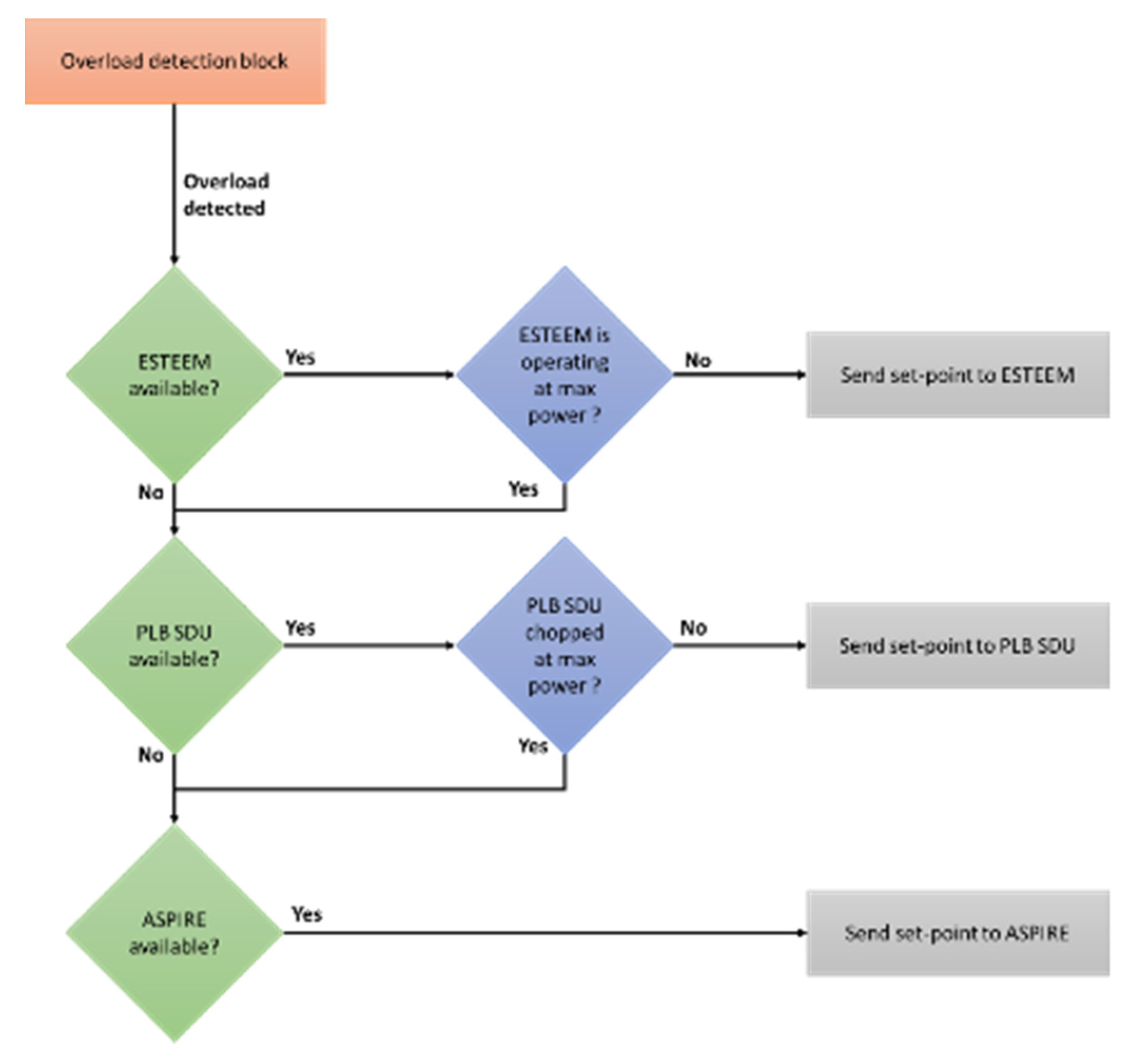
The above assumptions represent simplification to the E2-EM operation to allow for resource prioritization while considering uncertainties and real-time implementation limitations. The process described in Assumption 1 is depicted in
Figure 4.
The E2-EM estimates the set point for the active system, and the set points for other inactive systems are considered to be inaccessible and out of scope. Based on these assumptions, the OP can now be simplified, avoiding the use of computationally expensive MILP algorithms.
4.3.1. ESRS Rule-Based Logic
If available, the ESRS is the foremost resource to be activated when an overload is detected. Since it is the only resource selected to support the overload or fault condition at this stage, both
and
are set to zero. The OP can then be written as
which is subject to
Since the objective function
represents the power balance for the system at each time
, it can be set to zero and solved with respect to
:
The bounds for
can be obtained by replacing (15) in (13):
The aforementioned formulation implicitly covers two main aspects. First, through the and operators, it ensures the enforcement of constraint (13) and proper actuation of the set point in the presence of low/high SOC conditions as defined through (14). Moreover, in the presence of an over/under voltage condition, , and the variable would be constrained to be 0.
Then, the CSS OP problem can be written in the following simplified rule-based logic:
| Simplified Rule 1: |
| 1. | IF |
| 2. | |
| 3. | ELSE |
| 4. | |
| 5. | IF |
| 6. | |
| 7. | ELSEIF |
| 8. | |
| 9. | END |
| 10. | END |
Note that this simplified control rule is only valid during an overload event and does not take into account the recovery of the ESRS when the overload is concluded. For the recovery, we assume the simple heuristic rule described in Remark 1,
Section 4.1.1.
4.3.2. PLB1 SDU Rule-Based Logic
The same approach discussed for the ESRS is applied when the PLB1 SDU unit is activated. The PLB1 SDU is activated either when the ESRS is not available (i.e.,
) or when the contribution of the ESRS is not enough to cope with the overload condition acting on the power network (i.e.,
). In both cases, the variable
acts as a constant offset to the overall power balance. Assumption 2 provides information about the set point of for the SGN, which is
. When the PLB1 SDU is activated, the objective function (10) and constraint (6) are considered along with the aforementioned parameter settings for
and
Equation (10), when solved for
and then substituted in (6), produces the following inequality:
Note that the presence of
provides an offset with respect to the overall power balance, irrespective of the value of the variable itself. The OP problem in this case can be written with the following simplified rule-based logic:
| Simplified Rule 2: |
| 1. | IF |
| 2. | |
| 3. | ELSE |
| 4. | |
| 5. | IF |
| 6. | |
| 7. | ELSEIF |
| 8. | |
| 9. | END |
| 10. | END |
4.3.3. SGN Rule-Based Logic
Finally, the SGN system is activated when both the ESRS and PLB1 SDU are unavailable or cannot provide sufficient power to cope with the overload. The rule-based logic is given by:
| Simplified Rule 3: |
| 1. | IF |
| 2. | |
| 3. | ELSE |
| 4. | |
| 5. | END |
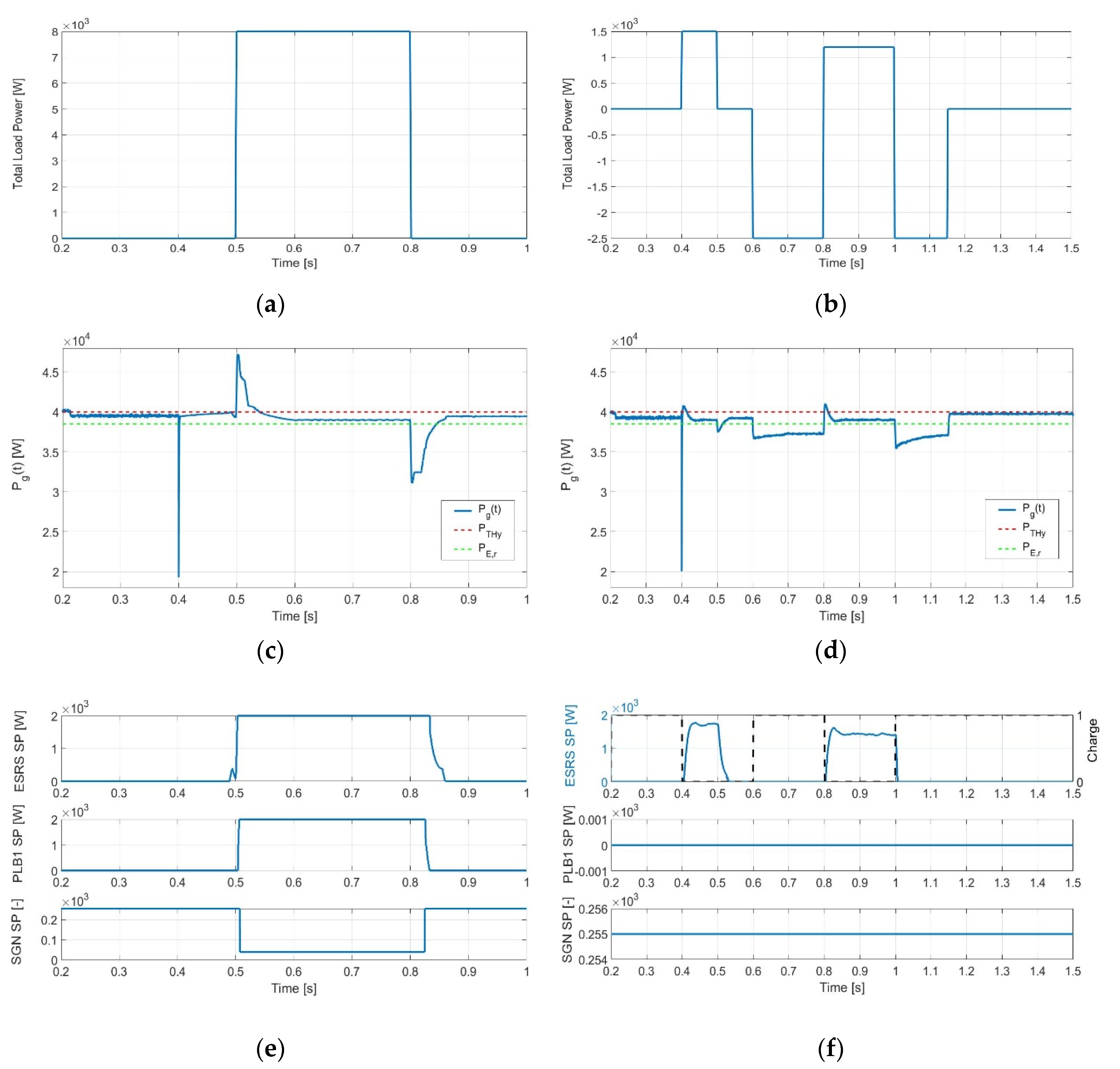
Based on the above analysis, the CSS OP problem can be replaced by three simplified rule-based logic controls, which were summarized in the above simplified rules 1–3. The simplified rules are optimal when assumptions 1 to 3 hold. They simplify the implementation of the CSS control from a complex MILP optimization to a simple inequality and function evaluation. In order to test the optimality and performance of the proposed rule-based logic solution, a MIL study of the control algorithms is presented in the next section.


 ,
, 


