1. Introduction
On the market there are many fire detection systems available. Many of them may work with a single sensor. These single sensor systems might cause false results as there are different factors to be considered when detecting fire, and false results may end up wasting energy, or worse, end up causing property damage. On the market there are two types of solutions: either they are cheap, such as sensors that might go off with the smoke from a cigarette, or they are too expensive, such as a sensor based on optical vision and head vision sensors.
In literature, different methods have been purposed by different researches to handle these kinds of circumstances. Some have utilized wireless sensor networks (WSN) with the integration of a global system of mobile communication (GSM) to create effective fire detection and warning mechanisms. Some researchers purposed image processing techniques and artificial intelligence based algorithms to execute different sets of actions depending upon the severity of the fire hazard, but every technology has its benefits and also its limitations with it [
1,
2]. In the quest of making a smart wireless sensor for fire detection, this research paper’s purpose is a Smart Fire Detection and Deterrent System (SMDD). The purposed system uses a combination of multiple sensors so that it can produce efficient result while keeping the cost affordable. The purposed system is based on fuzzy logic to make the decisive decision based on the severity of the given circumstances. The purposed system uses Arduino microprocessors. The purposed system utilizes the fuzzy logic-based algorithm to detect the fire and depending on the severity activates the alarm and sends an alert message to the authorities. If the situation is critical enough that it might be lethal to human life, the purposed system is smart enough to start human life support, which involves a water sprinkler and will also start the emergency exhaust system to reduce suffocation in that particular area [
3,
4].
Our system is based on the fuzzy logic which is the brainchild of Dr. Lotfi Zadeh of the university of California; the idea was proposed in 1960 [
5,
6]. In 1964, he presented the membership function, which has become the life force of the fuzzy set theory [
7,
8]. In 1965 the fuzzy set theory and the fuzzy logic theologies were introduced, which became the founding tone for the membership function and the rule set, which has a vital role in SMDD.
The rest of the paper is structured as follows:
Section 2 discusses the results of the literature review;
Section 3 explains in detail the equipment and methodology of the presented research for the proposed Fire Monitoring and Warning System;
Section 4 explains the results of the research in detail; and
Section 5 presents a conclusion of the presented research.
2. Related Work
Before the arrival of fuzzy logic in the spotlight, fuzzy set theory became the mainstay for the new research ground for researchers to come up with applications for the detection of fire [
9]. There were other ways that were proposed, which included artificial intelligence-based fields such as setting up neural networks or using a camera to detect changes in images using image processing or video-based technologies. As the cost of human life is above all, the use of various technologies has been proposed for the detection of fire at early stages [
10].
Hamdy et al. proposed a similar system with the combination of wireless sensors including temperature, light and smoke. These sensors provided the main data. This data became the foundation for an artificial neural network (ANN) that guided in the detection of fire in forests at an earlier stage. The SFFEDSS was purposed to detect the fire without the involvement of a human factor [
11]. Our system also uses multiple sensors, but the difference is for an indoor environment; we also use humidity sensors in addition to our system using AI algorithms to produce the final result instead of just depending on the results of a sensor alone.
Turgay et al. purposed an image processing system which uses chrominance information with the factor of luminance that are converted into YCbCr color space, and fuzzy logic rules are used as the definition for more efficient detection of fire pixels from non-fire pixels in order to avoid false fire alarms [
12]. Our system also uses the fuzzy logic algorithm, but the feature is the factor of multiple sensor, meaning if one of the sensor is defective or fails, the system will not become useless, it will use the results of other sensors to still provide results that can be acted upon.
Divya et al. came forward with the research for detection of fire with different techniques. As fire has different colors—yellow, red, orange, white—and many other objects that are not related to fire that may have the same color in order to identify fire, the purposed research used edge detection with the combination of motion detection and the area being covered with various thresholds in place to identify the existence of fire [
13].
Giovanni laneve et al. provided a technique to detect fire in the Mediterranean forest by using satellites with infrared image technology called SEVIRI images. The base idea was two compare two images with each other after an interval of every 15 min [
14]. Usage of satellite infrared imagery can be costly. Our system is designed to keep the cost to a minimum and still be able to provide effective results. Even if the sensor becomes faulty or damaged, the cost of replacing them is not high, so they are suitable for households as well factories and companies.
Haibing et al. presented a system in which multiple sensors were used for the detection of fire with short range to long range communication with the help of gprs. The base algorithm used in the purposed research was a BP algorithm which was used for detecting and anticipating the probability of fire at any given moment with the help of these sensors including carbon monoxide, smoke detection and temperature sensors [
15]. In our system we also utilize the power of smoke sensors to detect the presence of fire, but in addition to that our purposed system provides starting of a ventilation system that reduces suffocation. Tuan wei et al. described a method for detecting fire by using image processing in which wavelet transformation method was combined with the edge-area-information to detect the energy emitted by the frames to detect fire over a longer period of time for those areas which are left unattended [
16,
17].
Santoshinee et al. provided an algorithm for detecting fire using wireless sensors including temperature and humidity sensors [
16]. On top of these sensors for detecting fire the researcher also provides the algorithm to detect faulty nodes to produce more efficient systems and performed indoor experiments to validate the results for the algorithm [
18]. Navyanth et al. purposed a mechanism for detection of fire using robots with ultrasonic sensors mounted on them [
19]. The goal of the research was to detect and reach the designated area without causing damage to the nearby properties and avoid nearby obstacles. To achieve this goal, the purposed research used the distance of the obstacles from the robot with the help of turn around angles from the head of the robot to front, left and right, including other nearby robots using ultrasonic sensors. The purposed research used fuzzy logic algorithm as its base for the detection of fire [
20].The maintenance cost of managing robots can be high as the technology involved is complex and requires expert maintenance efficient result that can be achieved by our purposed AI algorithm power system with a heavy cost of maintaining, as the sensors involved in our system are easy to acquire and integrate.
Prathyusha et al. purposed an E-Nose Electronic-Natural oil factory sensor emulator’s sensor which used high end and state of the art sensors to detect smoke such as carbon dioxide co2 and carbon monoxide. The purposed system differentiates between fire and no fire particles in order to reduce the frequency of false fire alarms; another feature to extinguish the fire is with the help of a built-in fire extinguisher that activates when the sensor is absolute about the presence of fire, as a precaution [
21].
Faisal et al. purposed his research while keeping the focus on the security of homes against fire hazard and used multiple wireless sensors in order to detect fire and integrated the GSM technology to send a notification if such an event occurs [
22,
23]. Our system takes the data from the sensor, but for accuracy we use data for analysis in the AI fuzzy logic algorithm to provide efficient results.
Malykhina et al. purposed a system that uses a wireless thread interface at its core to detect fire at early stages in plants [
24]. The interface provides the facility to use the sensor to be moved freely around. These systems could easily be used as a temporary fire warning system by using multiple sensors while monitoring any changes in temperature, density of smoke and the composition of gas in the surrounding area [
25,
26]. Liu et al. presented his research regarding a smart bushfire monitoring system which uses cheap microcontrollers to detect fire and is incorporated with GSM technology to send SMS notification in case of fire occurrence. The purposed system also facilitates the GPS microcontroller in order to communicate the sensor information [
27].
Antonio et al. purposed an algorithm hour that integrated image processing technology with fuzzy logic to detect fire [
28]. In order to increase the efficiency of the system and in order to reduce false positives the algorithm uses dynamic motion test by analyzing the result produced by fuzzy logic when applied to analyze the motion of such areas that resemble fire colors [
29]. In our system Fuzzy logic is used for analyzing the results from multiple sensors to accommodate if the sensor even gets faulty data from other sensors and can be used to perform analyses for the detection of fire. Mingyi et al. purposed a mechanism to detect the fire using a neural network. The neural network used bp (Back Propagation) algorithm as base. The purposed system used a microcontroller to provide the necessary data to the algorithm in order to detect the occurrence of fire and the sensors used in the purposed model include CO, temperature and smog sensor [
30]. Muhammad Salihin et al. presented a mechanism to detect fire using smoke sensors and also provided a monitoring system so that in case of a fire the system could provide the monitoring mechanism to display wirelessly to help firefighters to pinpoint the location of fire, helping in the rescue process [
31,
32].
3. Methods and Equipment’s
The purposed system uses four sensors for getting the data to use it as input and based on the data collected from the sensors a rule based fuzzy logic is implemented. For SMDD MATLAB fuzzy Logic Toolbox capabilities are used for simulation work to provide an accurate picture and to also push the flexibility and scalability of system to next levels with respect to other systems [
33].
In SMDD, linear input data has been mapped to scalar output with a fuzzy logic system. In order to do that, different sets of operations were performed as mentioned below:
For the steps mentioned above each method has different sub methods to choose from, such as for fuzzification there is singleton fuzzification and grade fuzzification. For inference there is minmax inference, Takagaki_sugenu and Mamdani Fuzzy inference system; similarly for defuzzification, there is the centroid method, weighted Average method and mean-max membership method. In our purposed system the code for fuzzy logic control is written in C language using Arduino IDE, which is further integrated with Arduino UNO microcontroller, which is also controlling the sensors. The model for Arduino Board is ATmega328P.
Table 1 provides the description of the terms that are used in this paper.
3.1. Purposed Fuzzy Logic System Architecture
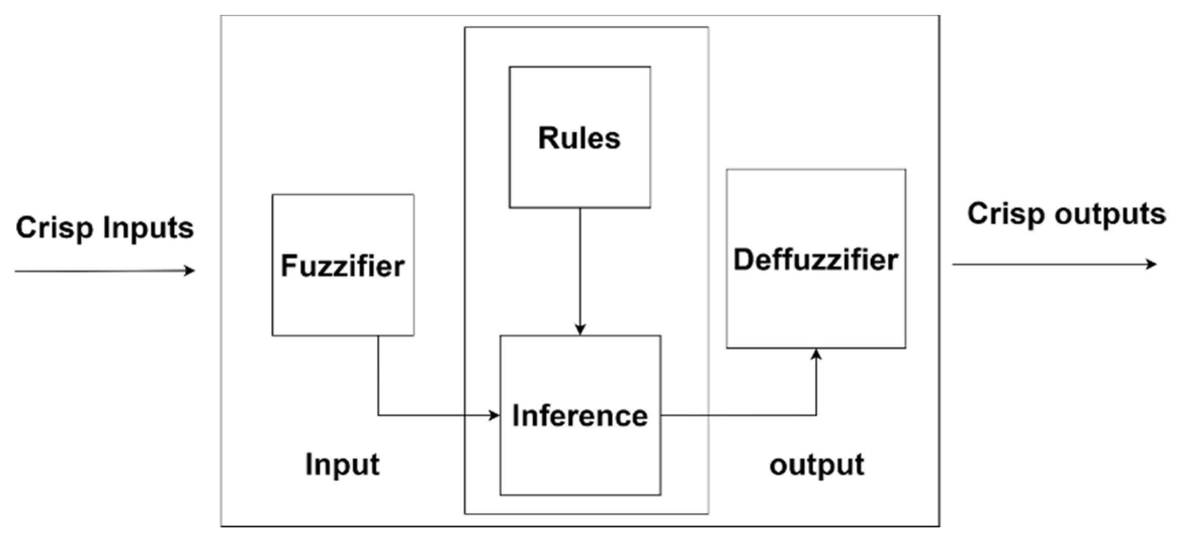
The architecture for the purposed fuzzy logic used in SMDD is shown in
Figure 1. Normally fuzzy set G is represented by a pair of (U,a) here U is the representation of universe of Disclosure and “a” is the membership function, for which values are assumed between the range from 0 to 1. The universe of disclosure plays a very important and vital role in this approach. The fuzzy set G within the Universe of information U could be defined as by being an ordered pair set of elements y which can be mathematically represented as:
Three parameters Q W E R are utilized in the system purposed. Where Q is the representation of temperature. W is the representation of humidity. E is the symbolic representation of smoke and Time is represented by R. Representation of degree of membership of x in Q is given by aQ(x). aW(x) is the representation of the degree of member ship function of x in Similarly the representation of degree of membership of x in E is given by aE(x) and for time the degree of membership of x is shown as aR(x). Equations (2) and (3) are the representation of the above-mentioned degree of membership of with respect to temperature, humidity, smoke and time.
The Equations (2) and (3) are defined to calculate the strength of the rule in the purposed system. Equation (2) shows union of four fuzzy subsets by using or operator in which fuzzy inputs and are combined by the fuzzy combination. Similarly, the equation three shows the intersection of four fuzzy subsets for which the “and” operator is used. The intersection of four fuzzy subsets is achieved by clipping the output membership function. In the purposed system the Equation (3) with (4) inputs are used to obtain the strength of a rule by combining both fuzzified inputs and the output of membership function. The linguistic variables as qualitative and quantitative can both be utilized to describe the fuzzy set. According to the definition of membership function, each point is to be mapped to the values between 0 and 1 in the defined universe of disclosure. The fuzzy rule in our purposed system is represented by rules to describe a piece of information; the fuzzy rules in this system are the most widely and commonly used approach for the representation.
Our Solution follows the process as described in the flow chart above of fuzzy logic.
The result from our sensors are the crisp input for the algorithm. Fuzzy inference is then applied for determining the matching degree of the input data with predefined rules in the fuzzy logic and decided which predefine rule is to be fired based on the input values. Then the centroid defuzzification process is used to produce the output values.
Algorithm 1 describes the working of fuzzy logic which is based on [
34] and fuzzy logic is represented in
Figure 1 with all of its components as mentioned earlier. The following algorithm implements the fuzzy logic system in this purposed solution SMDD.
| Algorithm 1. The Purposed Fuzzy Logic Algorithm |
- 1:
Define: The terms and the variables - 2:
Create: Membership Functions for The Purposed Solution - 3:
Create: Rule base - 4:
Construct: Crisp Inputs using Membership Function and convert them to fuzzy values - 5:
Evaluate: The Rules present in rule base - 6:
Combine: The Results of each rule - 7:
Construct: Output from non-fuzzy values
|
As per the purposed algorithm, the first step is to define the variables and terms. Sensors that are used to gather input in our purposed system are temperature, humidity and smoke. The term used to represent humidity is Humidity -S, the term to resent temperature is Temp-S and to represent smoke the term that is utilized in the purposed system is Smoke-S. The second step was to setup the membership functions, which play a very vital role because it is used to convert the inputs from the sensors known as crisp values to fuzzy values as input. These inputs are utilized by our rule base which was set up after the member ship function. The rule base consisted of all the rules checking the presence of fire at low to high using all the inputs provided from temperature humidity smoke sensors. Inference is made by utilizing the Fuzzy Rule base to check the intensity of fire based on the fuzzy inputs based on the result; the last step was to perform defuzzification method. The detail description of each of the component used in the algorithm is given below.
3.1.1. Fuzzification Method
In the fuzzification phase of the purposed fuzzy logic the input values from the humidity, temperature and smoke sensors are converted into fuzzy inputs. This conversion takes place with the help of membership functions which are explained in detail in the next section. Each value from the sensor which is being fuzzified has their quality represented by their membership function; for example the membership function for humidity sensor, Temperature and smoke sensor is given by “High”, “Mid” and “Low”, while the membership faction for time is valued by “Long” and “Short” and the fuzzification set is represented by the following relation (4)
Here the Z(x1) is there representation of kernel of fuzzification. This method when implemented the value if β is kept constant and the xi kept being converted to a fuzzy set Z(xi). Fuzzification provides the fuzzy inputs on which the rule base is applied to get the output on which critical decision are made depending upon the circumstances.
3.1.2. Membership Function
In the purposed solution the membership ship function is given by βG: X [0,1] according to this for a given fuzzy set G in which X represents the universe of disclosure and every value of X is mapped to a degree of membership ranging between the values from 0 to 1. In the proposed system, a graphic approach can also be provided where x is the representation of the values of universe of disclosure and the y is representing the degree of membership ranging from 0 to 1. In the purposed system triangular membership function is being used. Triangular member ship function according to definition has a lower limit and an upper limit b and third value m acting as a mean between the lower and upper limit which is represented as:
the reason for using triangular membership function is due to its simplicity to implement and that it provides efficiency and accuracy. For implementation of triangular membership function in the purposed system we have utilized the MATLAB “trimf” function.
The x axis in triangular member ship function is represented by three parameters gin as (a,m,b) these values represent the lower boundary peak and the upper boundary respectively. The above-mentioned equation can also be expressed in the form of min max operation as described in Equation (6).
In the purposed system the fuzzy logic is based on the Equations (5) and (6) with 5 variables in which 4 of them are the inputs which are collected from (Temperature, humidity, smoke and time) and one is output of the fuzzy logic system on which the purposed system makes decisions. There are three variables involved in the triangular membership function for each sensor which are given as a, b, c with the following property (a < b < c). The linguistic variable use in the purposed system with above mention membership function are following change rate in Temperature-S, change rate in Humidity-S, change rate in Smoke-S, Time and output variable showing the “fire chances”. The mentioned membership function is given as “trimf” function in the MATLAB fuzzy logic toolbox and is further explained in
Section 3 with each of the sensor mentioned here in detail.
3.1.3. Fuzzy Inference System Used for SMDD
The fuzzy inference system used in fuzzy logic algorithm is based on the if else rule, and a set of membership functions with the combination of fuzzy logic operators (and, or). In this purposed fuzzy logic algorithm fuzzy inference is use4d to map the fuzzy inputs to and fuzzy output. There are different inference systems available such as Mamdani fuzzy inference, Takagi-Sugeno Fuzzy Model and Tsukamoto fuzzy inference system. In the purposed system the Mamdani Fuzzy Inference system is used which was purposed in 1975 by Ebhasism Mamdani, which was used to control a boiler with a steam engine and boiler by utilizing a set of fuzzy rules that were obtained from a group of people working on the system.
The following are the steps that are used in Mamdani fuzzy inference system to get the computed output:
Step 1—Determine the fuzzy rules.
Step 2—convert crisp input using membership function to fuzzy input values.
Step 3—Set up the Rule base.
Step 4—Evaluate the fuzzy input on the bases of rule base and membership function to get the output.
Step 5—Combine all the outputs.
Step 6—Defuzzification of the output from the membership function.
In the Equations (7) and (8) there are three fuzzy values given as Q, W, E and operator is used here for applying intersection on these crisp inputs gathered from the sensors.
3.1.4. Defuzzification Method Used in the Proposed Fuzzy Logic
Defuzzification is the process of reducing the fuzzy member into a crisp member or crisp set. In the purposed SMDD system the output evaluated with the help of rule set that were given in the form of if-then else statements. These rule bases are being used as the knowledge base to get the computed output. In this step the scaler values of the system are fuzzified by applying the rules on them which results in generation of a fuzzy output result which converts this into a scaler quantity. There are different methods available for defuzzification described below:
3.1.5. Max Membership Method
This methodology is limited to peak output function. It is represented mathematically as:
3.1.6. Weighted Average Method
In weighted average the function is weighted using the maximum membership value.
3.1.7. Centroid Method
This method is developed by Sugeno in 1985. Mathematical representation of the defuzzied output for centroid method is given as following:
Here X* is the defuzzied output. βG is the aggregated membership function. In the purposed system the shape is obtained using “and” fuzzy operator by clipping the output of membership function based on the rule strength.
Defuzzification is done in SMDD using Centroid Defuzzification Method and MATLAB fuzzy logic toolbox.
4. Implementation of Smart Fire Detection and Deterrent (SMDD)
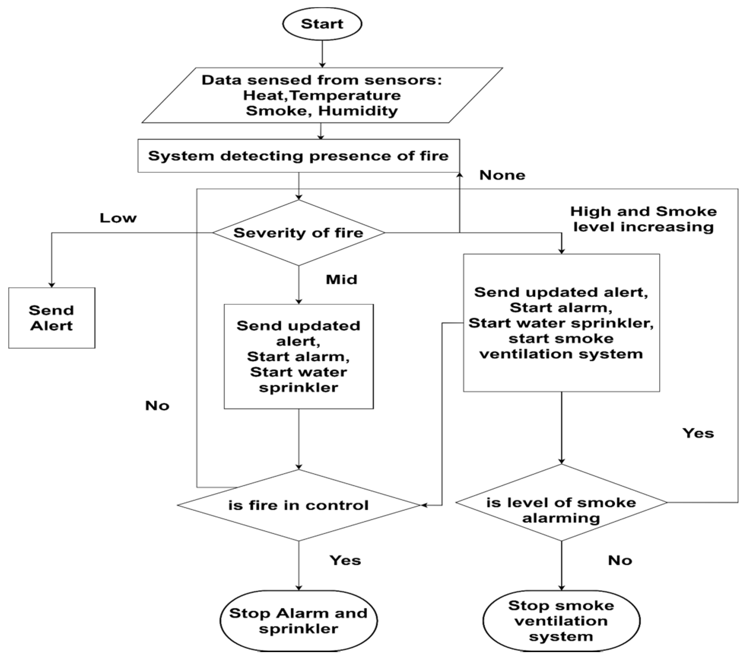
The purposed SMDD system used multiple sensors to detect fire presence. The sensors that are used in this purposed solution included temperature sensor, humidity sensor, smoke and flame sensor. The flame sensor is first sensor that goes off if it detects the presences of flame. If the flame sensor detects presence of fire, then temperature humidity and smoke starts sensing the environment and recording the inputs. The workflow of the purposed system can be seen in
Figure 2.
As defined in the workflow of the purposed system the sensors are attached with Microcontroller that senses the environment. The second step in workflow is to sense the presence of fire with the help of a flame sensor as soon as the sensor detects the presence. As per Flow chart, a decision is to be made based on the severity of the fire. The severity of fire here is detected by using the AI fuzzy logic algorithm, in which Fuzzy inference is then applied for determining the matching degree of the input data with predefined rules in the fuzzy logic and decided which predefine rule is to be fired based on the input values. Then the centroid defuzzification process is used to produce the output decision value. Based on the result, as per flow diagram system either sends the alert or starts the water sprinkler, then the system waits for the next result as per the flow diagram cycle to send the alert or to stop the water sprinkler and alerts if the situation is under control.
4.1. Hardware and Software Used for the Implementation of SMDD
In the purposed solution different sensors that are used include MQ series MQ-7 smoke sensor along with DHT22 temperature and humidity sensor. The flame sensor is used for detecting flame. In order to power these sensors and perform operation the Arduino UNO microcontroller is used. The details and specification for the above-mentioned sensors are discussed below:
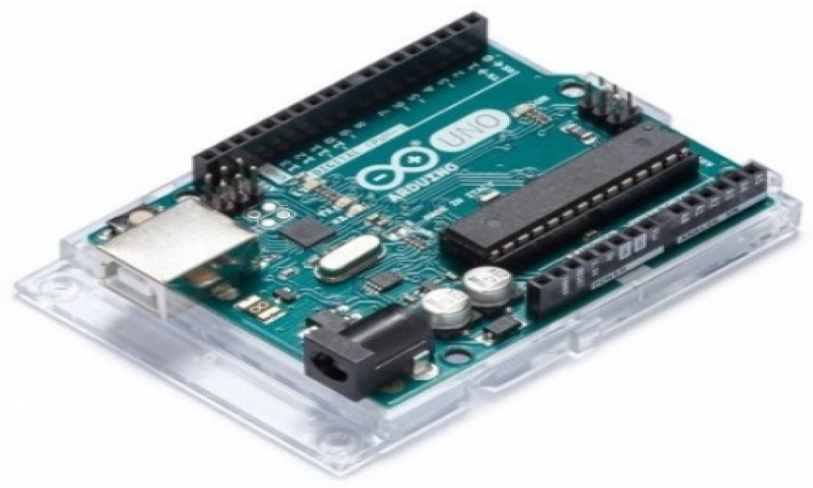
Arduino UNO microcontroller is a microcontroller board based on ATmega328. Arduino is an open-source platform. The Arduino Uno board has 14 digital input/output pins it has 6 analog inputs from A0 to A5. From the 14 pins 6 pins can be used as PWM output. The crystal oscillator on this board is of 16 MHz a USB connector. It also has a power jack and a reset button as shown in
Figure 3.
Features of the Arduino UNO:
4.1.1. Temperature and Humidity Sensor (DHT22) Sensor Module AM2302
The DHT22 humidity and temperature sensor is used to detect both temperature and humidity of the environment. The DHT22 has three pins available on it: one for digital input, one for power and the last one for ground. These pins are attached with the micro controller. Dht22 sensor senses the temperature in centigrade and humidity value is presented in percentage as shown in
Figure 4.
DHT22 senses temperature in between the range from −40 °C to 80 °C; the range for humidity scented by the DHT22 is in from 0% to 100%. The DHT22 has transformation distance of 100 m. In order to configure DHT22 with Arduino microcontroller using Arduino IDE DHT22 library is used.
4.1.2. DHT22 Specifications
- ■
Operating Voltage: 3.5 V to 5.5 V
- ■
Operating current: 0.3 mA (measuring) 60 uA (standby)
- ■
Output: Serial data
- ■
Temperature Range: −40 °C to 80 °C
- ■
Humidity Range: 0% to 100%
- ■
Resolution: Temperature and Humidity both are 16-bit
- ■
Accuracy: ±0.5 °C and ±1%
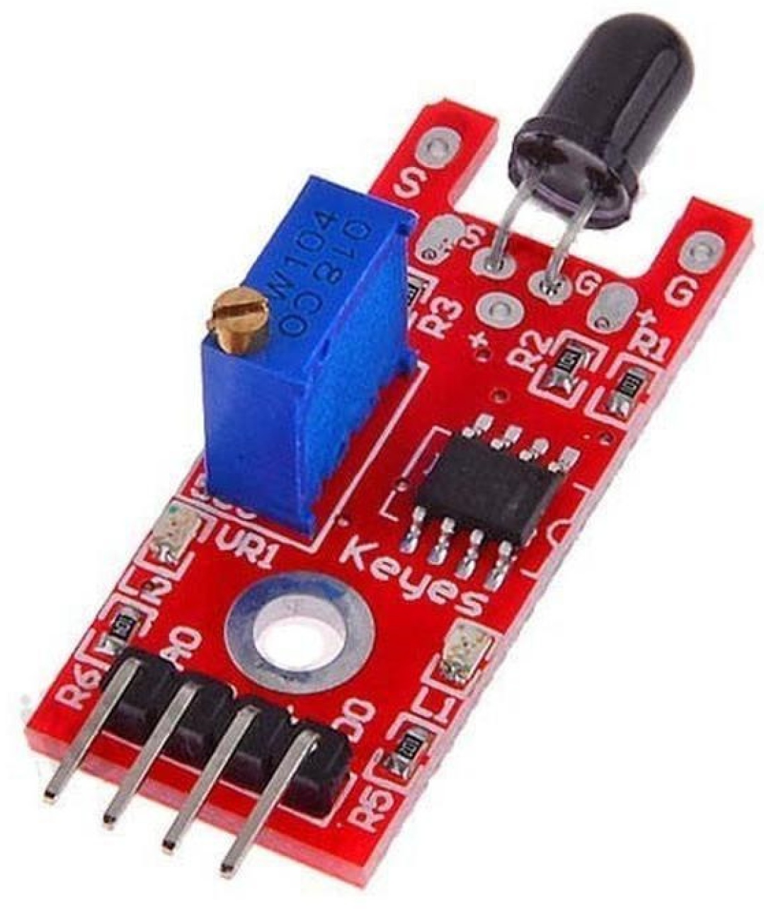
Flame Sensor: In our proposed system, a flame sensor is used to detect the presence of flame initially with wavelengths ranging from 760 nm to 1100 nm as shown in
Figure 5. Flame sensor integration with Arduino Uno microcontroller is done by attaching a ground pin of sensor with microcontroller ground pin and the A0 pin of the sensor was attached to microcontroller A0 pin. The flame sensor is powered with a 5 V power input from the micro controller; the code is written for the flame sensor in the Arduino Ide.
4.1.3. Flame Sensor Features
- ■
LM393 comparator chip
- ■
Range of Detection: 760 nm to 1100 nm
- ■
Voltage: 3.3 V to 5 V
- ■
MaxOutput Current: 15 mA
- ■
Outputs Values: 0 and 1
- ■
Angle of Detection: near to 60 degrees
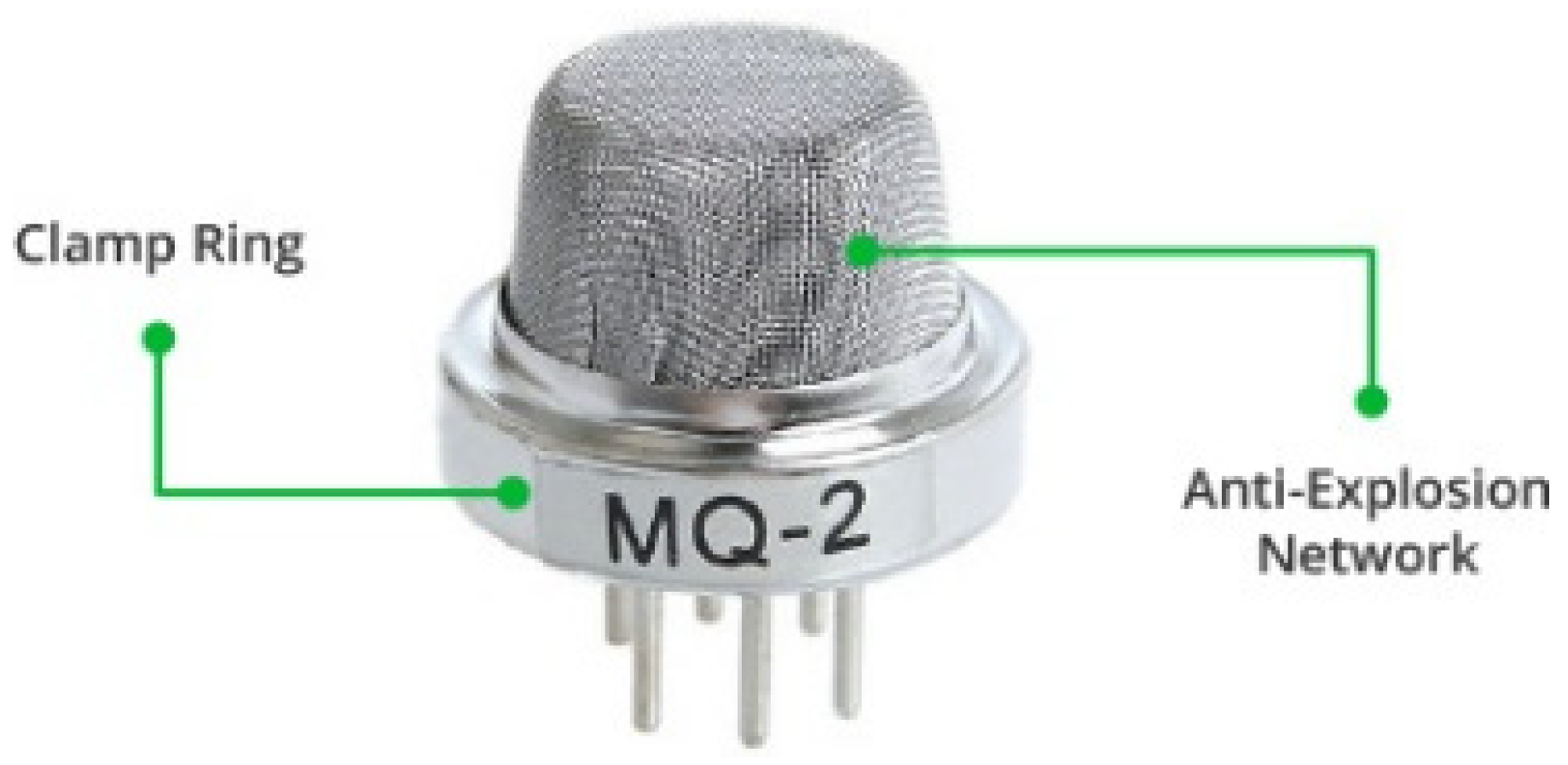
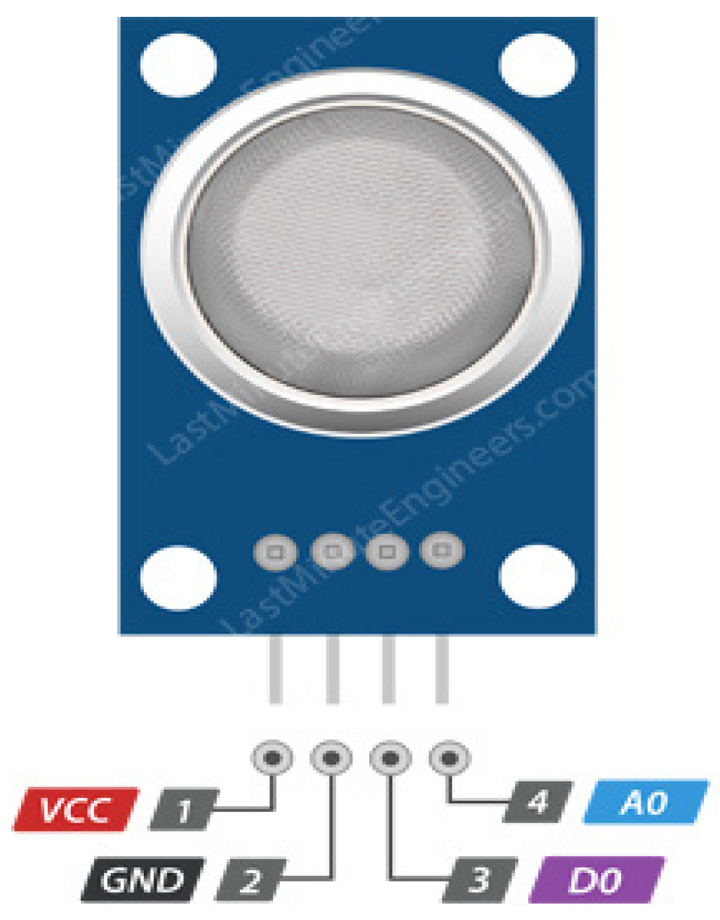
Smoke Sensor MQ2 Gas sensor is an efficient sensor of sensing smoke alcohol hydrogen methane and carbon monoxide in the air. MQ2 is a metal oxide-based sensor; there is another name used for this sensor—“Chemiresistors”; using the implementation of simple voltage divider, the gas presence can be detected by MQ2 sensor. MQ2 is powered by 5 V of DC voltage and 800 mW is drawn out by the sensor as shown in
Figure 6 and its specification in
Figure 7. The sensor has a steel mash over it that is called an anti-explosion network which gives it the capability to sense flammable gas without exploding internally, which makes it more ideal in our fire hazard-based situations. This mesh acts as shield as well by allowing only gas elements through, due to which the accuracy of readings also increases. The sensing element in the sensor is composed of Aluminum Oxide (AL
2O
3) based ceramic with a coating of Tin Dioxide (SnO
2). The Tin Dioxide is the most important material being sensitive towards combustible gases [
35].
4.1.4. Smoke Sensor MQ2 Specifications
- ■
Working Voltage is +5 V
- ■
Can detect Alcohol, LPG, Hydrogen, CO, Propane and even methane
- ■
Analog output voltage: 0 V to 5 V
- ■
Digital Output Voltage: 0 V or 5 V
- ■
Duration of preheat is 20 s
- ■
Provides both digital and analog sensor
- ■
VCC provides power to the module. It is connected to 5 V output from Arduino Uno microcontroller.
- ■
GND represents the Ground Pin.
- ■
D0 provides our system with a digital output of the presence of combustible gases.
- ■
A0 provides analog output.
4.2. Program for the Micro Sensors in Arduino IDE
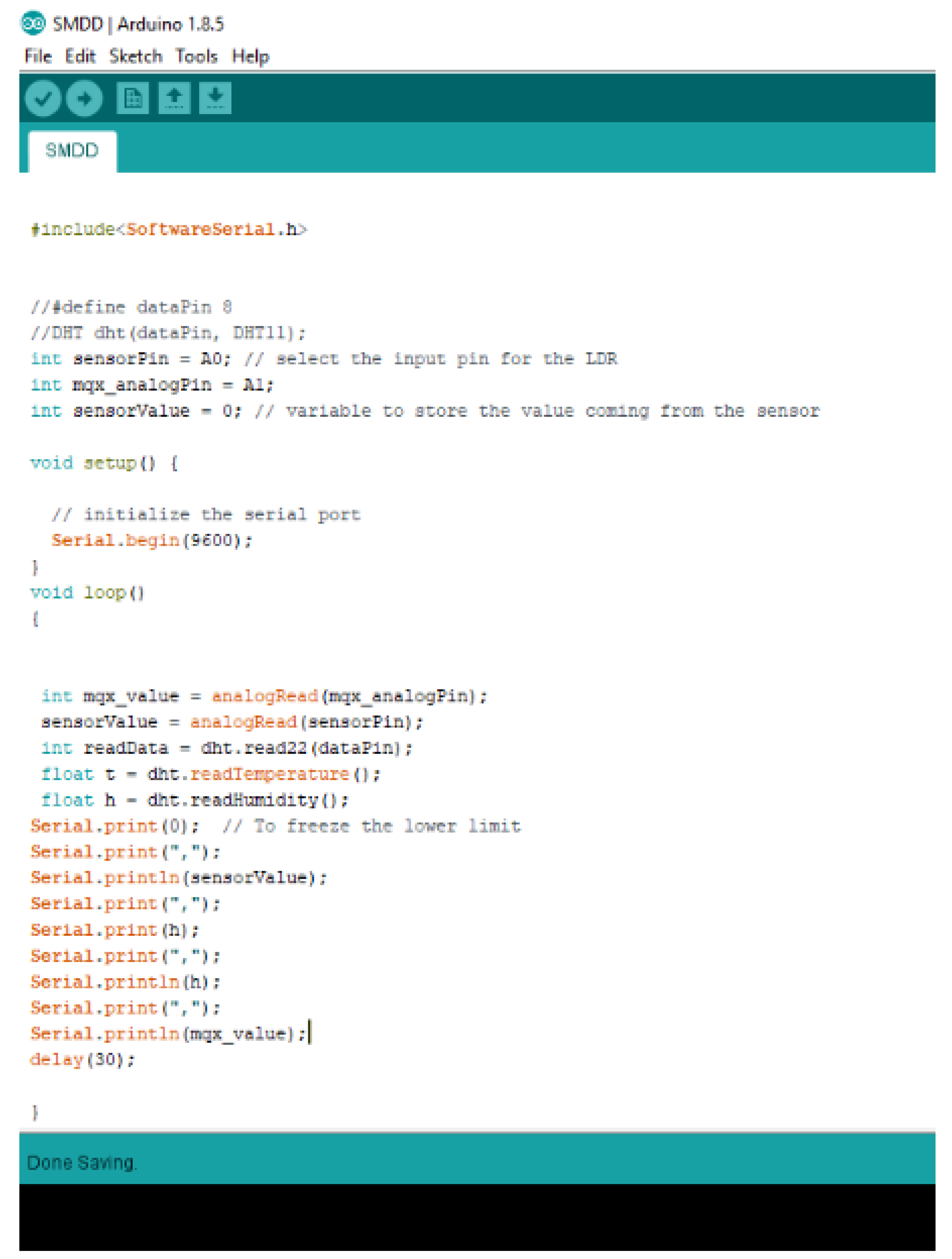
After the hardware configuration of all the sensors with the microcontroller, in order to read the sensors value and record them Arduino IDE 1.8.5 was used in which code was written in C language, the only library used was for DHT22 to sense the humidity and temperature. DHT22 is a library available online for the configuration of the sensor. Once we were able to read the data, we were able to generate the real time graphs of sensor sensing the environment in real time; the code for that is shown in the figure the input from the code allowed us to calculate Universe of Disclosure for the simulation to work on the MALTAB fuzzy logic tool box as shown in
Figure 8.
4.3. Graphical Representation of Sensors with Crisp Values
In this purposed system, there are three inputs from the following sensors: flame, Temperature, Humidity and smoke sensor. Given below are the graphical representations of how the environment affects each one of the scenes in the presence of fire as well as absence of fire room temperature. There are two graphs for each of the sensors described below one with the presence and another with absence of fire.
4.3.1. Graphical Representation of Flame Sensor
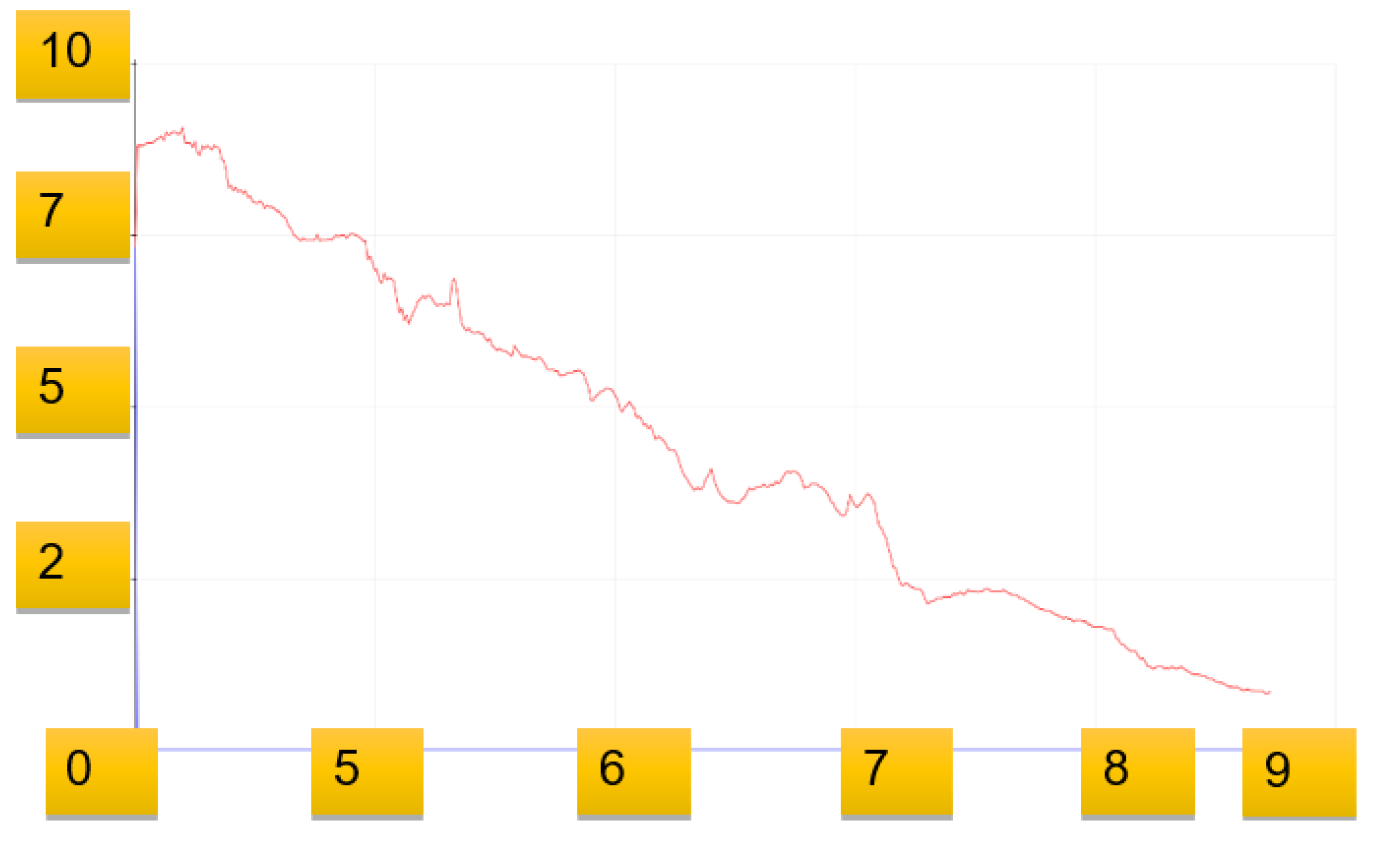
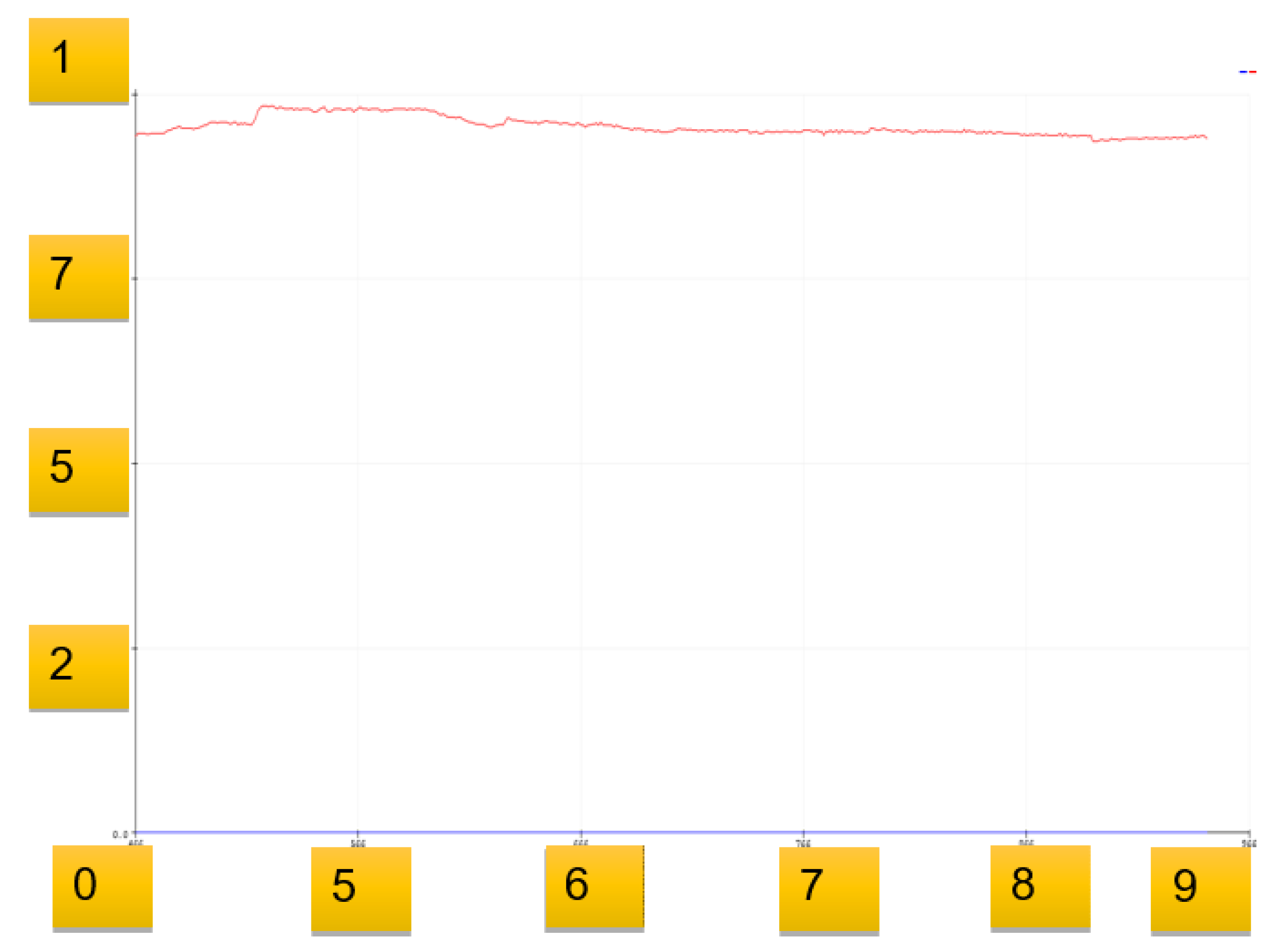
Flame sensor KY-026 in the purposed system is used to detect the presence or absence of fire. The reason for using it is its sensitivity to IR wavelength. In this system, for flame sensors we consider the analog output from the sensor which is a real time output voltage signal on the thermal resistance. As can be seen in
Figure 9, the graphical representation of the flame sensor analog output is steady and provides a voltage signal above or near 980.
Flame sensor KY-026 in the purposed system is used to detect the presence or absence of fire.
Figure 9 represents the graphical representation of the flame sensor analog voltage signals output. In the presence of fire, as soon as the flame starts the values of the output signal start to decrease; depending upon the intensity of the flame, the values drop significantly. The sensor is highly sensitive to the intensity of fire, as in the
Figure 10 the graph shows that as the intensity of the fire starts to increase, the sensor voltage signal starts to drop. As presented in the graph, the values drop from 980 up to below 100 as the intensity of the flame continues to increase.
4.3.2. Graphical Representation of DH11 Humidity Sensor
In the purposed solution for checking the humidity, the DH11 sensor comes into play. For power we have used 5 v power supply from the Arduino board. The reason for selecting the DH11 sensor is for its accuracy in detecting humidity between the range of 0 to 100 percent.
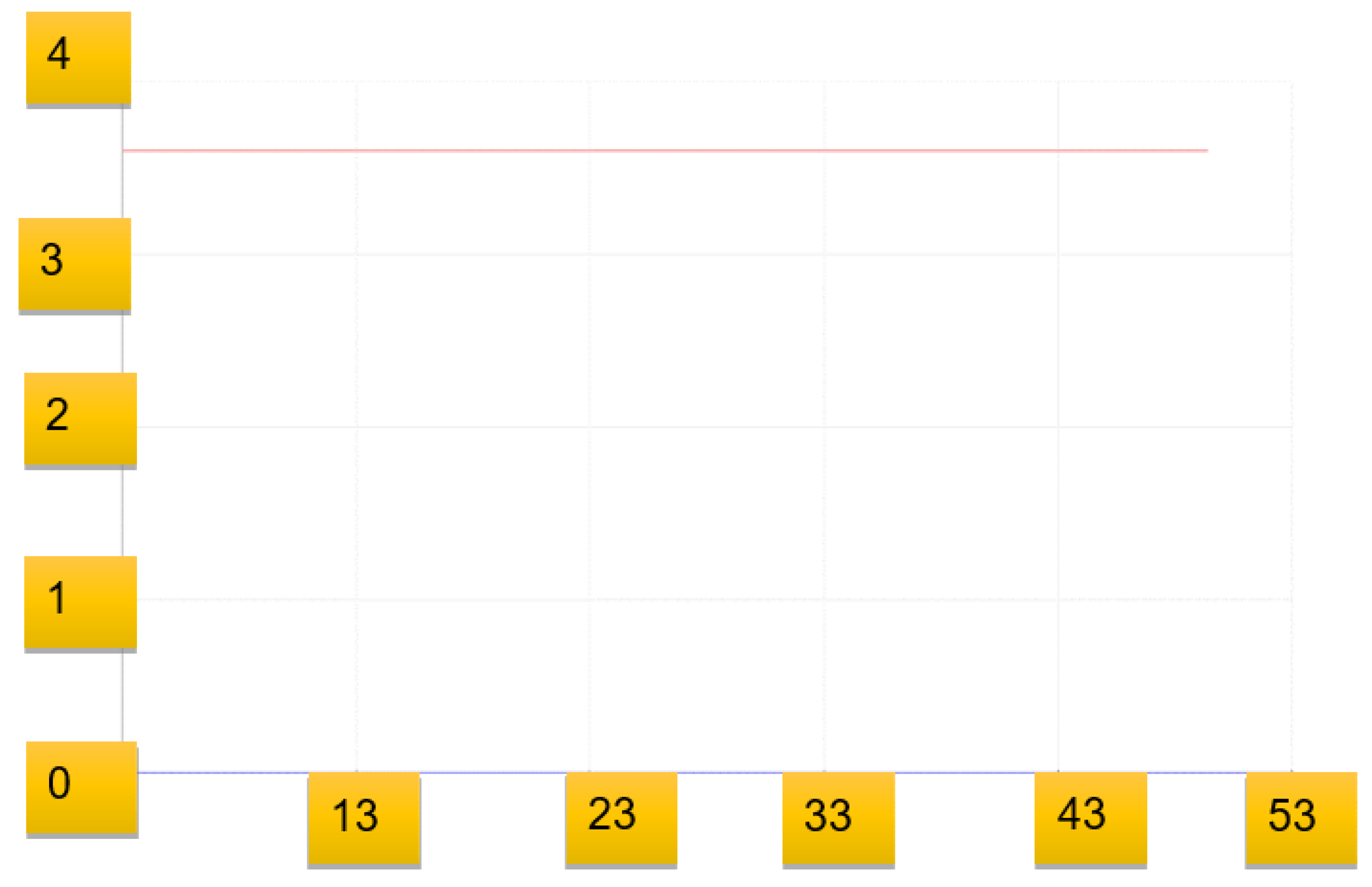
Figure 11 is the graphical representation of a humidity sensor sensing humidity in percentages at room temperature; as can be seen, the humidity is near 37–38%.
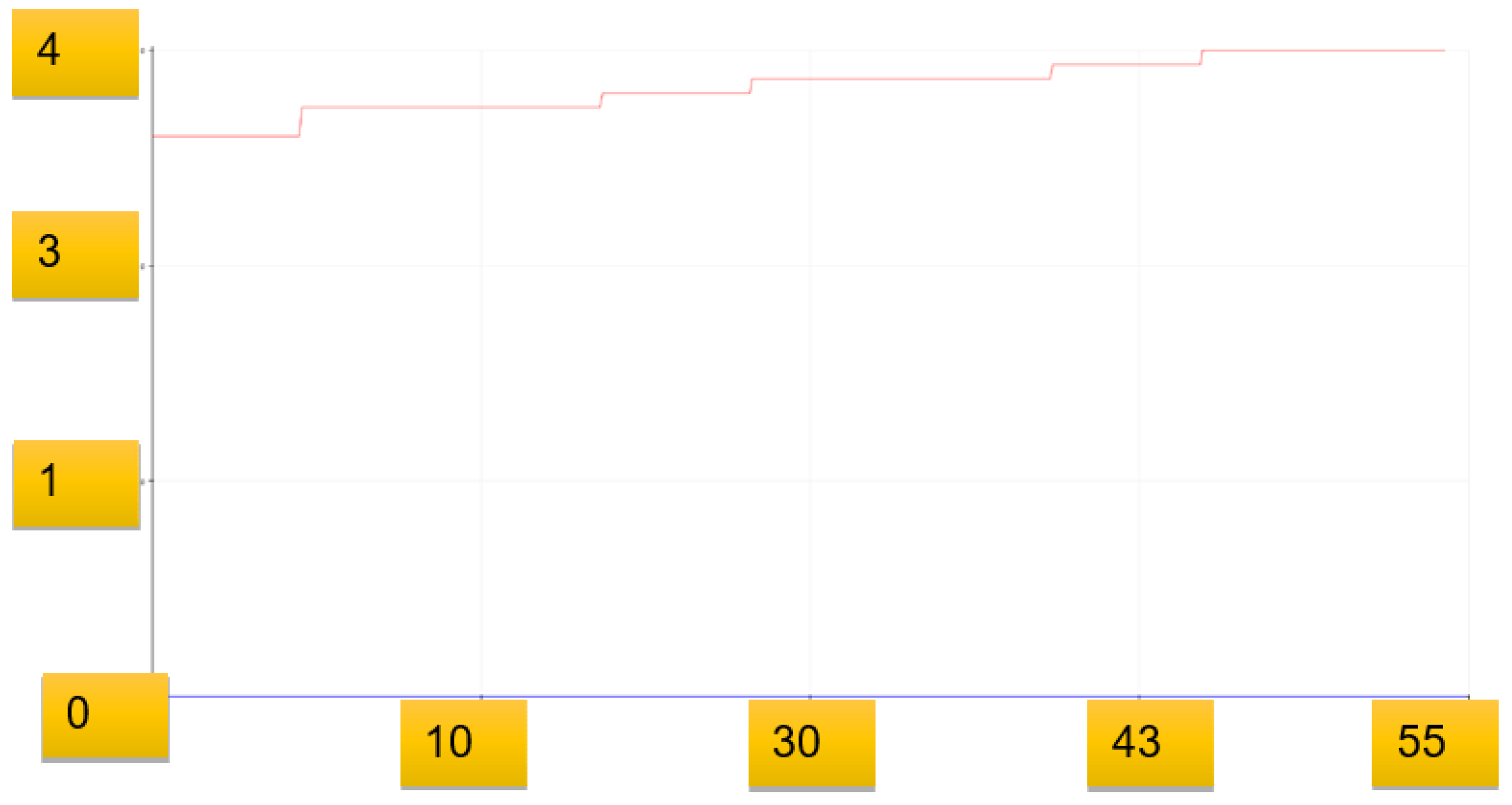
Figure 12 and
Figure 13 shows the graphical representation of a humidity sensor sensing humidity in percentages in the presence of flame as the humidity starts to decrease. As soon as the temperature starts to rise, the same can be seen in the graph where the humidity is gradually decreasing as the temperature keeps on increasing, because as the temperature increases due to fire, the moisture of the surroundings decreases.
4.3.3. Graphical Representation of DH11 Temperature Sensor
In order to keep an eye on the temperature in the purposed system for sensing temperature, the DH11 sensor again plays a vital role. The sensor is powered by a 5 volt power supply from the microcontroller and has the ability to detect temperatures in the following range: −40–80 °C. The figure shows a graphical representation of the output of DH11 sensor while sensing temperature at room temperature; as can be seen, the temperature is at a constant value of 36 °C.
Figure 14 is the graphical representation of a Dh1 sensor sensing temperature in the presence of gradually increasing fire; as can be seen from the graph, the sensor is capable of detecting a gradual increase in temperature accurately.
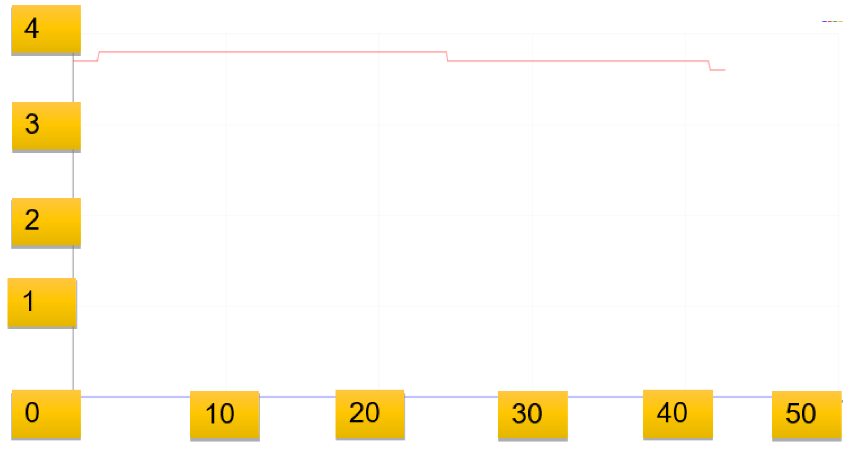
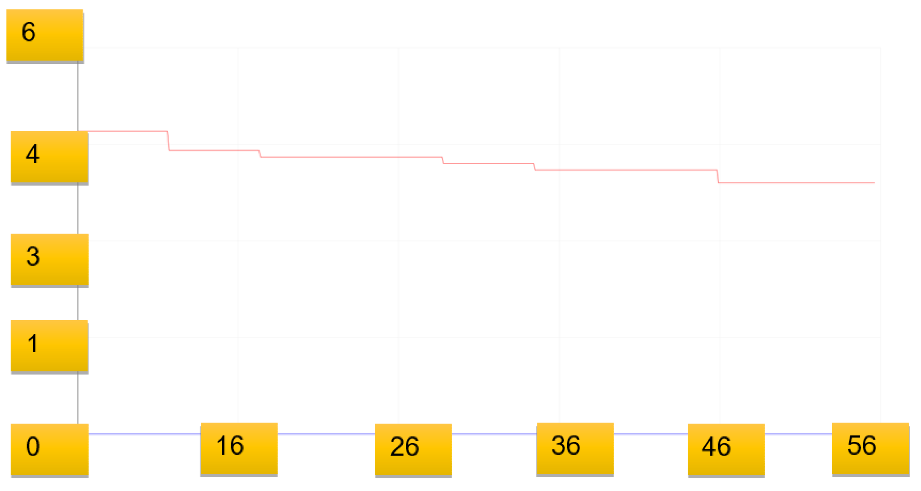
In order to make our purposed system smart enough and to provide life support to people if the intensity of fire increases to such a level as might cause suffocation, our system utilizes the MQ2 smoke sensor which detects the intensity of the smoke created by the fire. The sensor is powered with a 5 V supplied from the microcontroller. If the smoke reaches a critical level, the lives of people caught in that fire might be at risk, and our system is smart enough to start a ventilation process to provide life support.
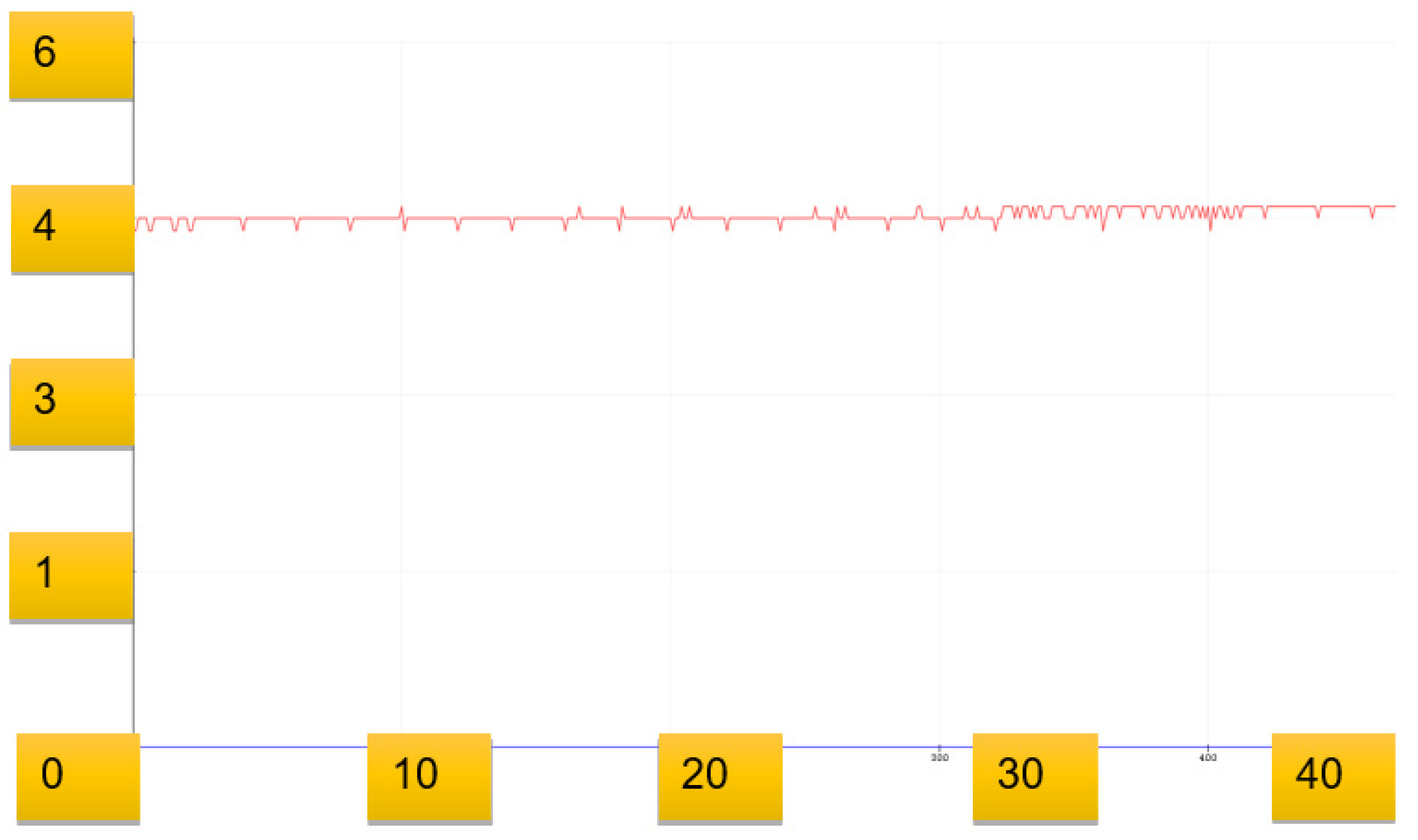
Figure 15 provides the graphical representation of smoke levels at room temperature in analog voltage signals; the value is consistent and is at 46 with small variations, which means there is no smoke present at room temperature.
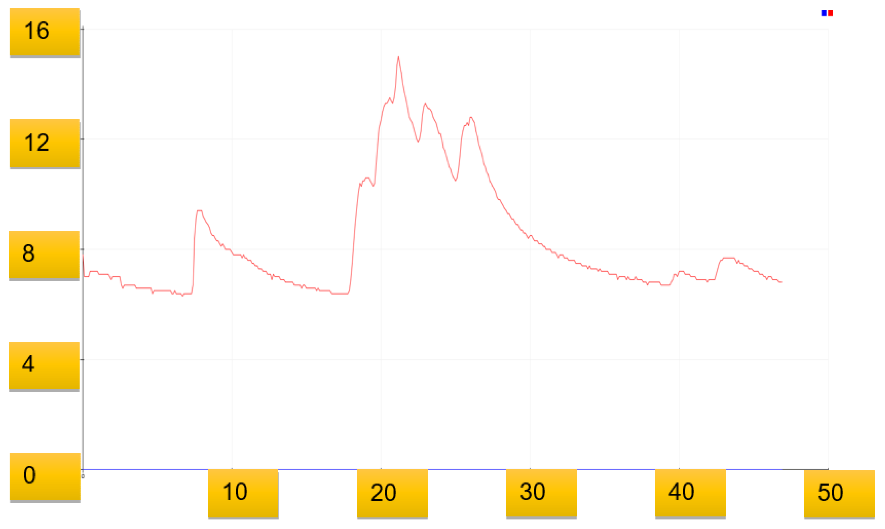
Figure 16 is the graphical representation of smoke sensor providing output in analog voltage signals in the presence of flame and smoke.
4.3.4. Graphical Representation of DH11, MQ2 and Flame Sensor
In order to explain how our system acts in a critical situation when the fire becomes a hazard, our graphs describes how the sensor acts at room temperature and how a critical situation affects the values of the sensor, which makes it possible to handle critical scenarios.
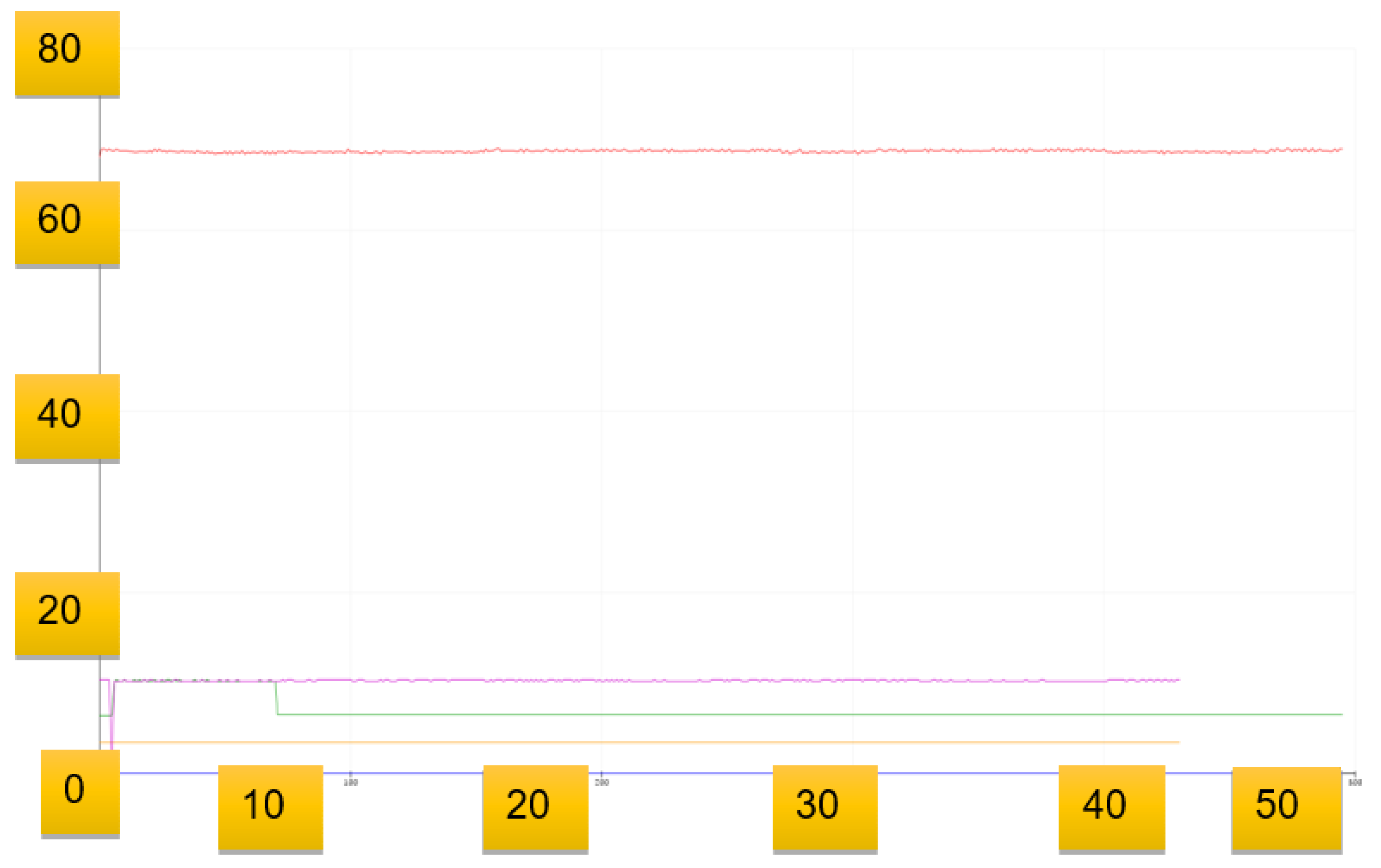
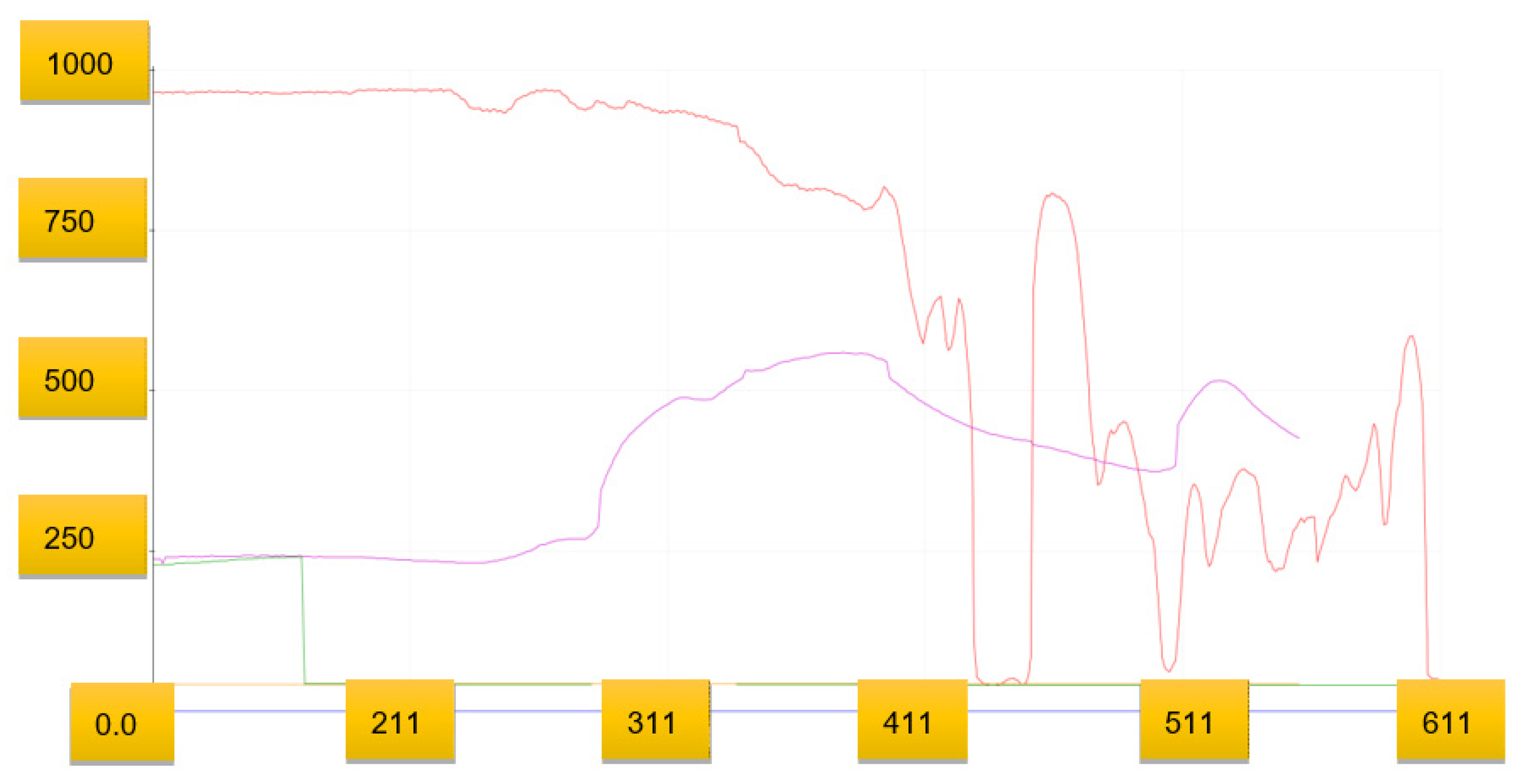
Figure 17 is the graphical representation of all the sensors at room temperature including smoke, humidity, temperature and flame sensors. As can be seen, the flame sensor shows an analog output signal at 980 and the smoke sensor shows the voltage signal between the ranges of 48–50. Humidity is at a value in the range of 40 percent and temperature is constant at about 36 °C.
Figure 18 shows the graphical representation of all the sensors in the presence of smoke and flame. As can be seen, the output voltage from the flame sensor is decreasing, which will alert that flame is indeed present and all the sensor values will then be used to make a decision using the fuzzy logic algorithm. Humidity increases as temperature increases due to fire, and the value temperature in degrees sensed by the DH11 sensor continues increasing above 40 °C. As can be seen in the graph values, the smoke sensor also senses the smoke due to providing an increasing analog voltage signal going above 260.
4.4. Records for Fuzzy logic Based on Sensors Data
The simulation work was done in MATLAB using the assistance of fuzzy logic toolbox for the purposed solution. In order to test whether the fire is present, there are a number of scenarios taken in account with the presence of fire and the absence of fire under harsh conditions on both ends with respect to humidity smoke and temperature sensors. The scenario also accounts for the time interval so that a better decision can be made about the intensity of fire if such a case arises. The data was gathered in real time from the sensor and was saved based on the data universe of disclosure for each of the sensors established.
In order to calculate Universe of disclosure for the purposed system simulation to work in MATLAB, data is gathered and displayed in
Table 2. The data is collected and stored by the sensor in real time where each column represent the values of the sensors captured. The first column represents the Time interval that was recorded in minutes for each sensor value and in each iteration, time is continuously recorded as it increases while sensors senses the environment and decisions are updated with the new result, while the second column is the representation of temperature sensor data. The third column is the representation of humidity in percentages data which shows how the humidity is affected as the times move on and fire is detected. The fourth column represents the presence of smoke, the value representing how the presence of smoke affects the smoke sensor as it detects smoke starting due to the presence of fire. In
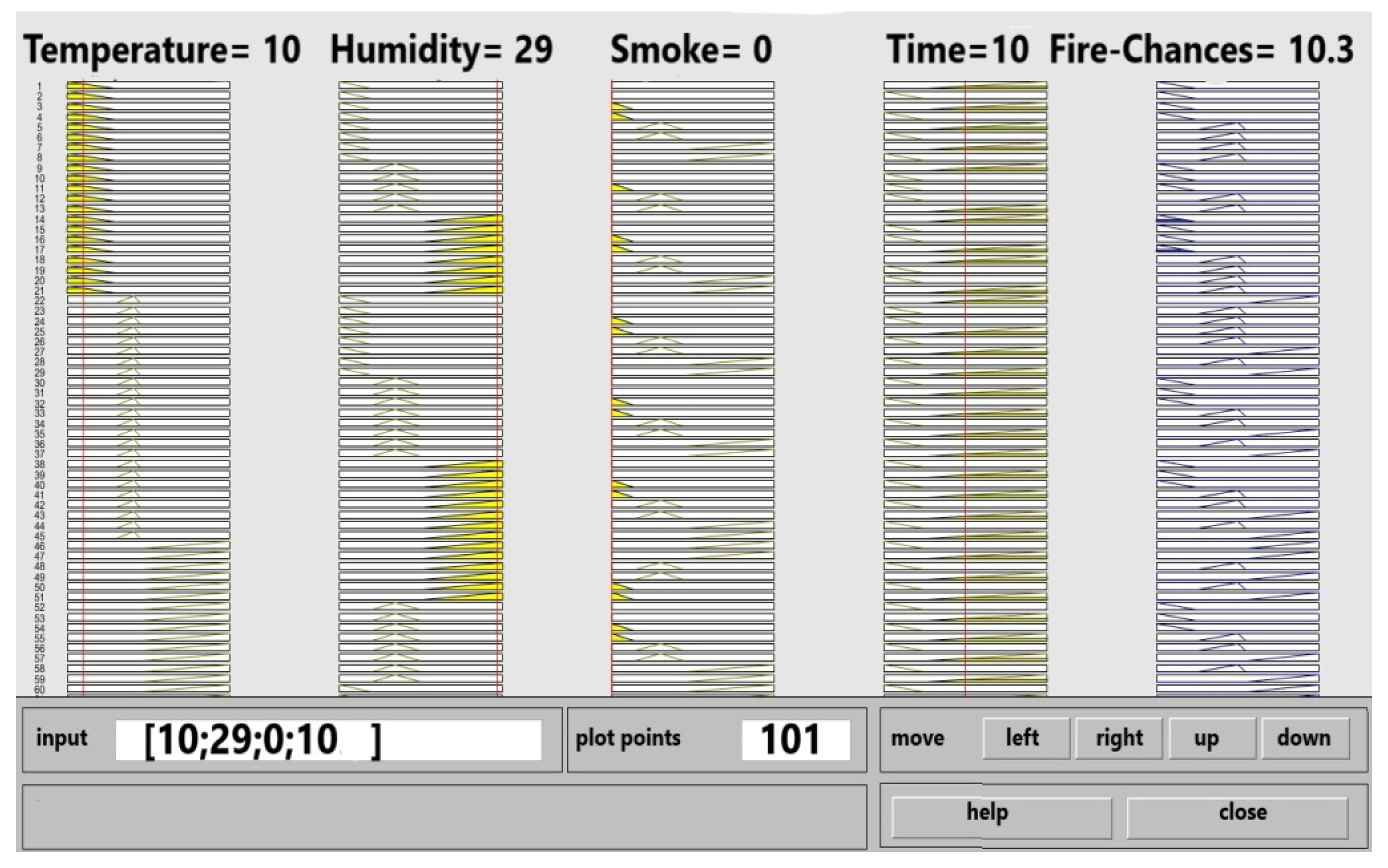
Table 2, the first iteration shows at time 2 min that the temperature is 10 °C and humidity sensed is 30%, while smoke is 0 at second time (fifth minute) the temperature stated increasing to 29 degrees and humidity decreasing to 28 percent, and the smoke sensor senses the value at 30. When time is recorded at 10 min, the temperature is 36 degrees and humidity drops to 15 with smoke at a value of 100. In
Table 3 for Experiment 2, in the second iteration when time is recorded at a value of 2 min, the temperature sensor records the temperature of the environment at a value of 26 °C and humidity is recorded by the humidity sensor at 22%, while smoke is 16%. In the fourth iteration when time is recorded at value of 12 min the temperature sensor records the temperature of the environment at a value of 35 °C and humidity is recorded by the humidity sensor at 17.8%, while smoke is 222.23%. For simulation, more than 70 experiments were done with more than 1000 values; based on this record we can set the Universe of Disclosure which is described below in Universe of Discourse for the values of membership function, meanwhile likewise the same as shown in
Table 4 for experiment number 3.
In
Table 5, the first column is representation Universe of Disclosure for linguistic fuzzy variable of Temperature sensor (Temp-S). For example, if the temperature of the particular area is 28 °C it will lie in the 0–30 °C range. If the temperature at any moment is 50 °C, then it lies in the range of high, which is starting from 45 °C up to 100 °C. The second column, which is Universe of Disclosure for the linguistic fuzzy variable Humidity (Humidity-S); for example if humidity is 29%, then it will be considered high as it lies in the high range which ranges in between 15–30%. The third column is representation of the Universe of Disclosure for a smoke sensor. The fourth column is the representation of universal of disclosure for Fire-Chances; this column represents the output at which different fire handling mechanisms will be activated and decisions are taken by the purposed system. The fifth column represents the times Universe of Disclosure, which holds values for short- and long-range and is measured in minutes. Based on these Universe of Disclosure for each of the linguistic fuzzy variables, different rules are applied.
4.5. Universe of Disclosure Configuration Representation on MATLAB
MATLAB provides fuzzy controller block, by which we can simulate the fuzzy logic control in order that first we enter the fuzzy variable with the inputs and based on those inputs we set up membership function. On these membership functions, a rule set is defined by which we get results on output that are interpreted using the procedure of fuzzy inference in order to do all that. The MATLAB fuzzy tools box for ease provides different editors and views to set up this data. In order to achieve our result for this purposed system, each of those views and editors are used. We used MATLAB 2018 version to provide the simulation result. In order to start this whole process, one has to enter the command of fuzzy in the command window, upon which fuzzy toolbox opens, and here we enter the variable state, their name and set our desired behavioral options.
4.5.1. Fuzzification Implementation in MATLAB
In fuzzification as described in fuzzy logic, crisp values are taken as input and are represented by a fuzzy linguistic variable with the help of membership function. in our purposed research, five inputs are taken into account: flame change in temperature, change in humidity change in time and smoke, and one output is evaluated based on the results of these inputs, known as fire-chances. Flame sensor variable is a constant because it is used to represent weather so its use is just for checking flame presence, and then all the rules are applied on the values captured after confirming that if fire is present by the rest of the sensor, the smoke humidity temperature and time are used in simulation of fuzzy logic to determine the chances of fire.
Membership Function for (Temp-S) temperature sensor: In
Figure 19 LOW, MID, High are the three linguistic fuzzy variables used for representation of Temp-S. The
y-axis value is a range between 0 and 1, respectively. The
x-axis value is represented by a range between 0 and 100. Where the linguistic fuzzy variable low resides between 0 °C to 30 °C and medium variable resides in between the range of 30 °C to 45 °C. The linguistic fuzzy variable High is represented by the range from 45 °C to 100 °C; these values are based on the Universe of disclosure calculated for the temperature sensor (Temp-S) described in
Table 3.
Membership Function for (Humidity-S) humidity sensor: In
Figure 20 LOW, MID, High are the three linguistic fuzzy variables used for representation of Humidity-S. The
y-axis value is given in a range between 0 and 1, respectively, for
x-axis value is represented by a range from 0 to 30, where the linguistic fuzzy variable low resides between 0% to 6% and medium variable resides in between the range of 6% to 15%. The linguistic fuzzy variable High is represented by the range from 15% to 30%, these values are based on the Universe of disclosure calculated for the Humidity sensor (Humidity-S) described in
Table 4.
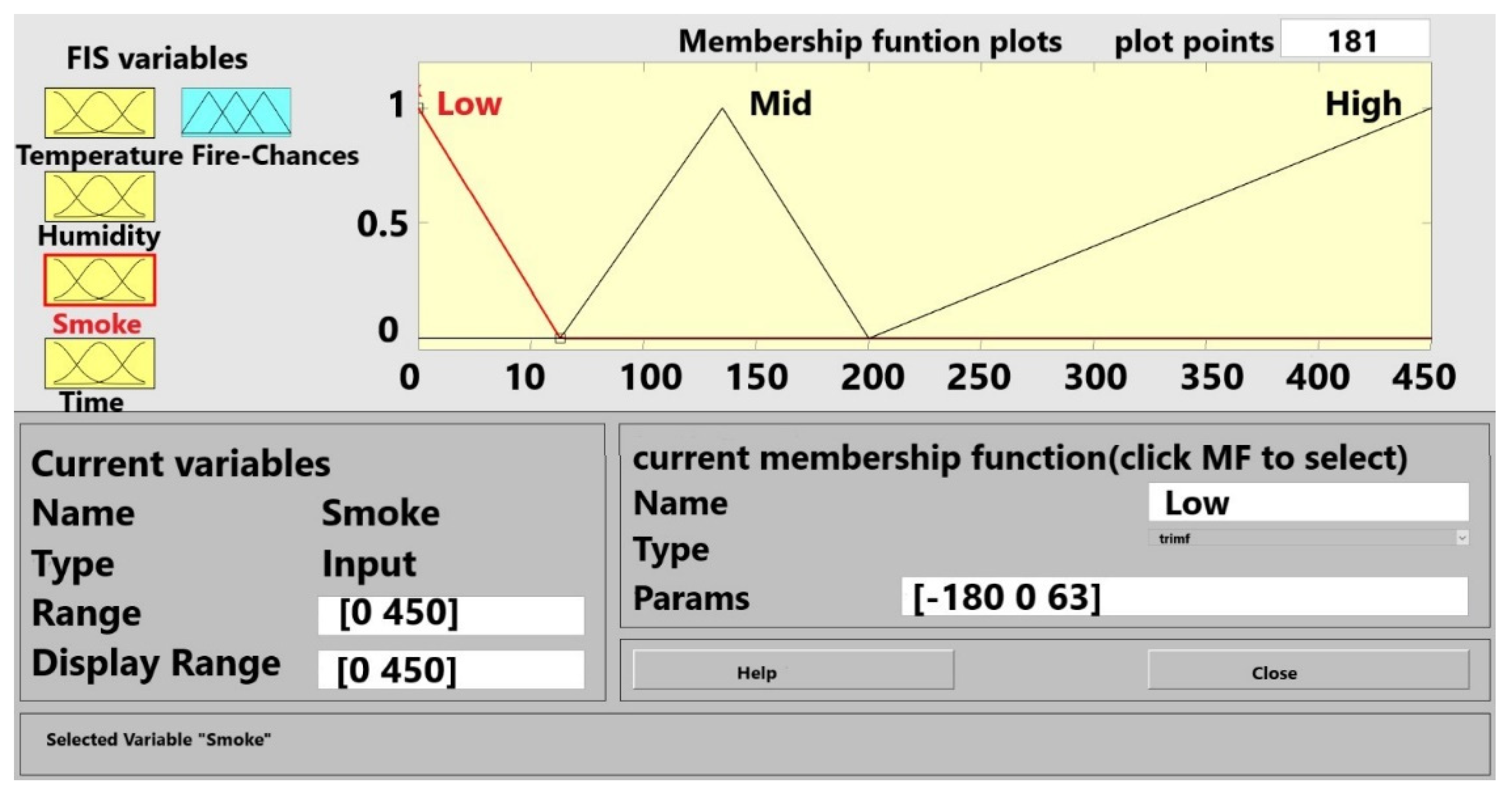
Membership Function for (Smoke-S) Smoke sensor: In
Figure 21, LOW, MID, High are the three linguistic fuzzy variables used for representation of Smoke-S. The
y-axis value is represented by a range from 0 to 1, respectively, the
x-axis value is represented by a range from 0 to 30, where the linguistic fuzzy variable low resides between 0 to 55 value and medium variable resides in between the range of 55 to 250 values. The linguistic fuzzy variable High is represented by the range from 250 to 450 values; these values are based on the Universe of disclosure calculated for the Smoke sensor (Smoke-S) described in
Table 5.
Membership Function for Time sensor SHORT and LONG are the three linguistic fuzzy variables used for representation of Time. The
y-axis value is represented by a range from 0 to 1 respectively the
x-axis value is represented by a range from 0 to 100. Where the linguistic fuzzy variable SHORT resides between 0 to 5 min and Long variable resides in between the range of 5 to 20 min. These values are based on the Universe of disclosure calculated for the Time described in
Table 6.
4.5.2. Membership Function for Fire Chances
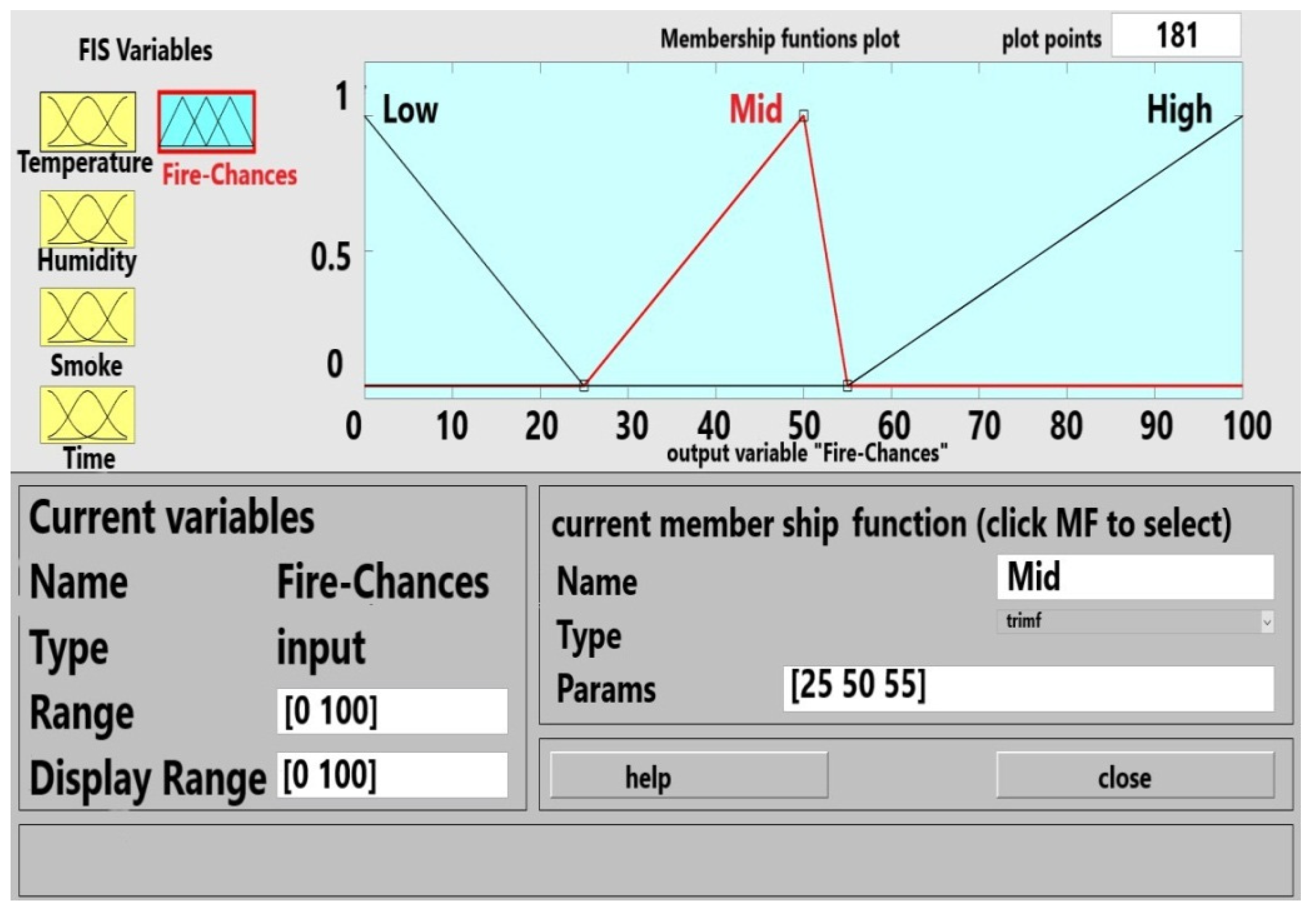
In
Figure 20, LOW, MID, High are the three linguistic fuzzy variables used for representation of Fire-Chances. The
y-axis value is represented by a range from 0 to 1, respectively, the
x-axis value is represented by a range from 0% to 100%, where the linguistic fuy variable low resides between 0% to 25% value and medium variable resides in between the range of 25% to 55% value. The linguistic fuzzy variable High is represented by the range 55% to 100%
4.5.3. Setting Up Fuzzy Rules on MATLAB Using Fuzzy Rule Editor
After the membership function has been defined, the next step is to define the fuzzy rule set in Fuzzy logic. IF-Then is the provided way to represent the rules and this can be configured in the MATLAB rules editor. In this purposed system, four fuzzy inputs are used, on which IF-Then conditions are applied to get the desired output. As a flame sensor is used to detect presence of flame, it’s a Boolean value as displayed in
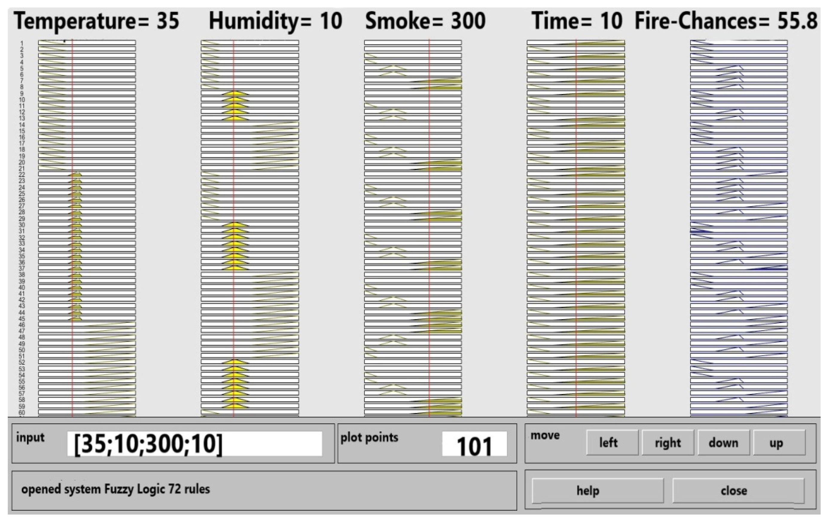
Table 4; if the fire is present then our proposed system will move to the next step and the values of smoke, temperature, humidity and time will be recorded to determine the chances and intensity of fire. If the flame sensor gives a false value, then the system will not move forward to the next step and will continue to sense the presence of it. In our purposed system for fuzzy rule set we have 72 rules to check the intensity of fire with respect to time being short and long. On the basis of these results, the system takes action to handle the situation depending upon the intensity. If the output is low, our purposed system sends an alert.
4.5.4. Rules for SMDD (in Case of When Time Is Short and Smoke Is Not Present)
Table 6 demonstrates all the rules in the case when the time is short, and the smoke is not present, but the fire has been detected by the flame sensor, so the system has started to evaluate the condition based on the sensor values. In this table, as smoke is not present, the focus of rules is on Humidity-S and Temperature-S, and is described by Low, Mid and High.
Rules for SMDD (in case of when time is long and smoke is not present):
Table 7 is similar to
Table 5 where smoke is not present and fire is detected by the flame sensor, but with one exception: these time rules are the representation of the system when time is considered “long” instead of “short”.
4.5.5. Safeguard Mechanisms Based on the Outcomes
In our purposed system, different safeguard mechanisms are placed and they are activated according to the situation. These mechanisms are described in
Table 8 with their respective actions. For example, if the fire occurs and the outcome is slow, then an alert will be transmitted to the management about the presence of fire. In such a scenario where the output of fuzzy logic system is high, then the alarm will be activated, followed by an alert message sent to the management, and the water sprinkler will also be activated in order to get the situation under control. Air ventilation support is also provided in high chances of fire when such a scenario occurs where the high percentage of smoke is present and may result in suffocation.
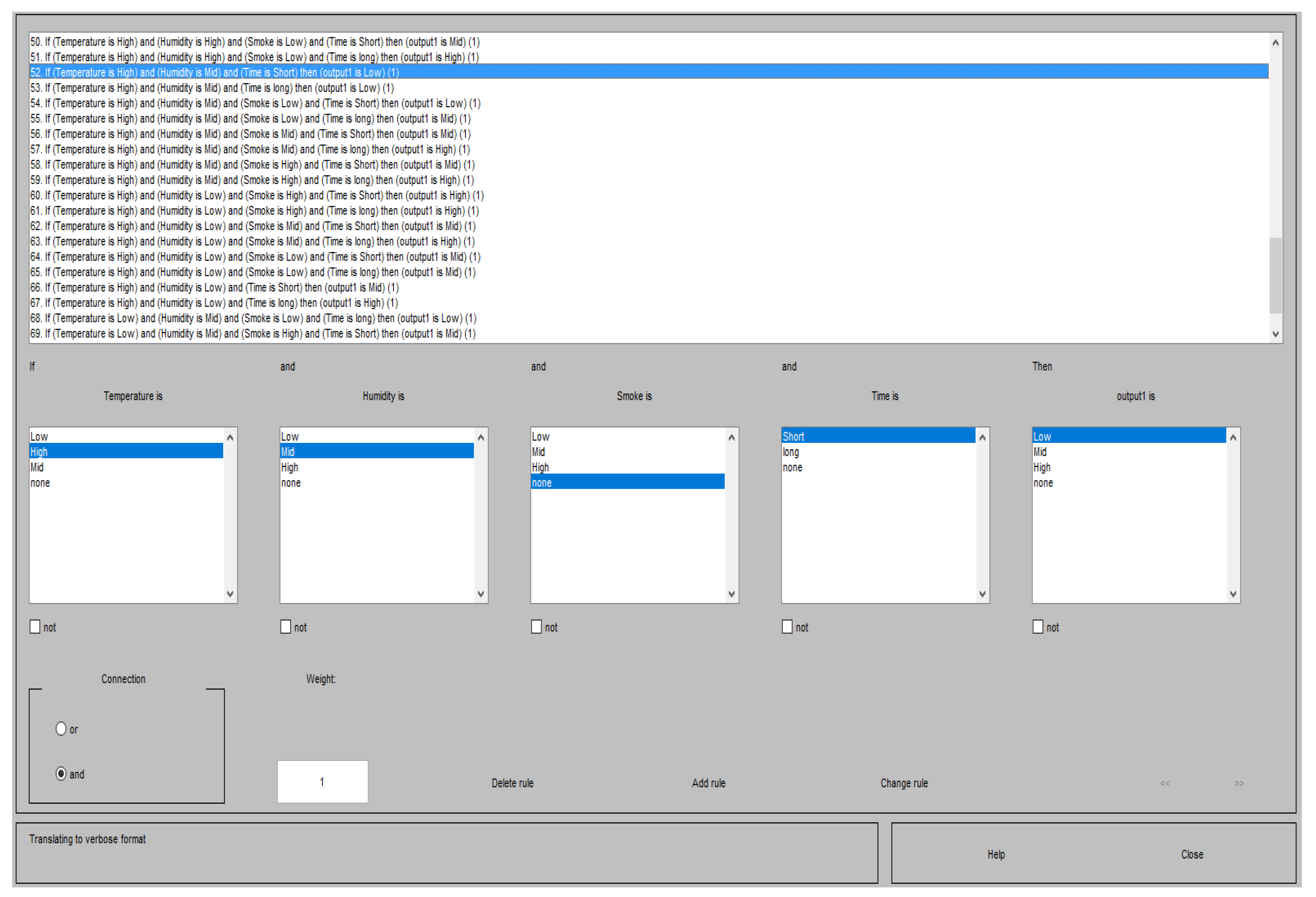
4.5.6. Adding Rules Using Rules Editor
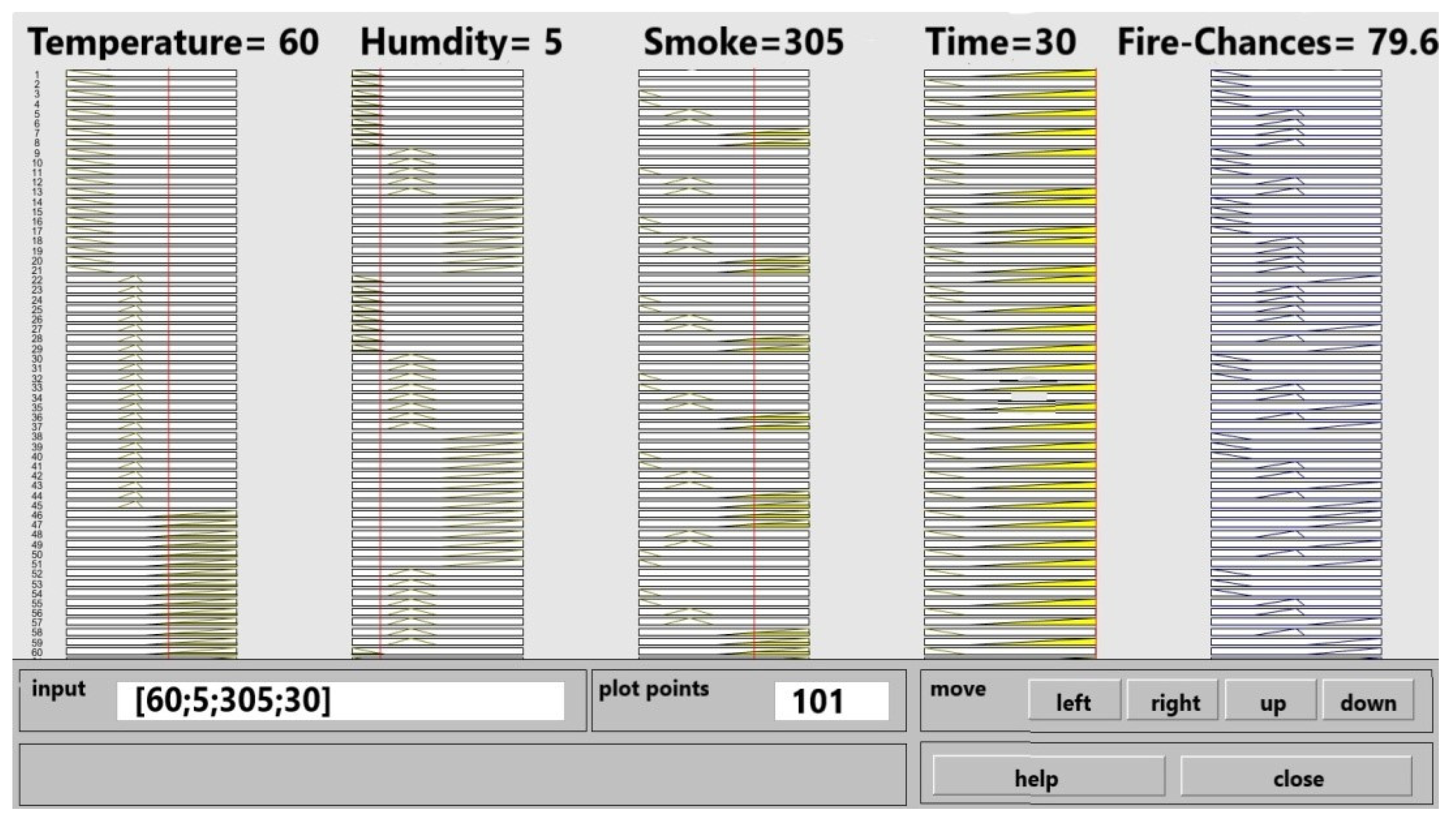
After we have calculated all the possible rules with respect to the SMDD sensors, the next step is to add these rules in the MATLAB rules editor. In the rule editor we provide with our inputs with a list of low, mid and high value, and an output with possible outputs to choose from and operation to apply either and/or this can be seen in the
Figure 22.


 ,
, 


