Article

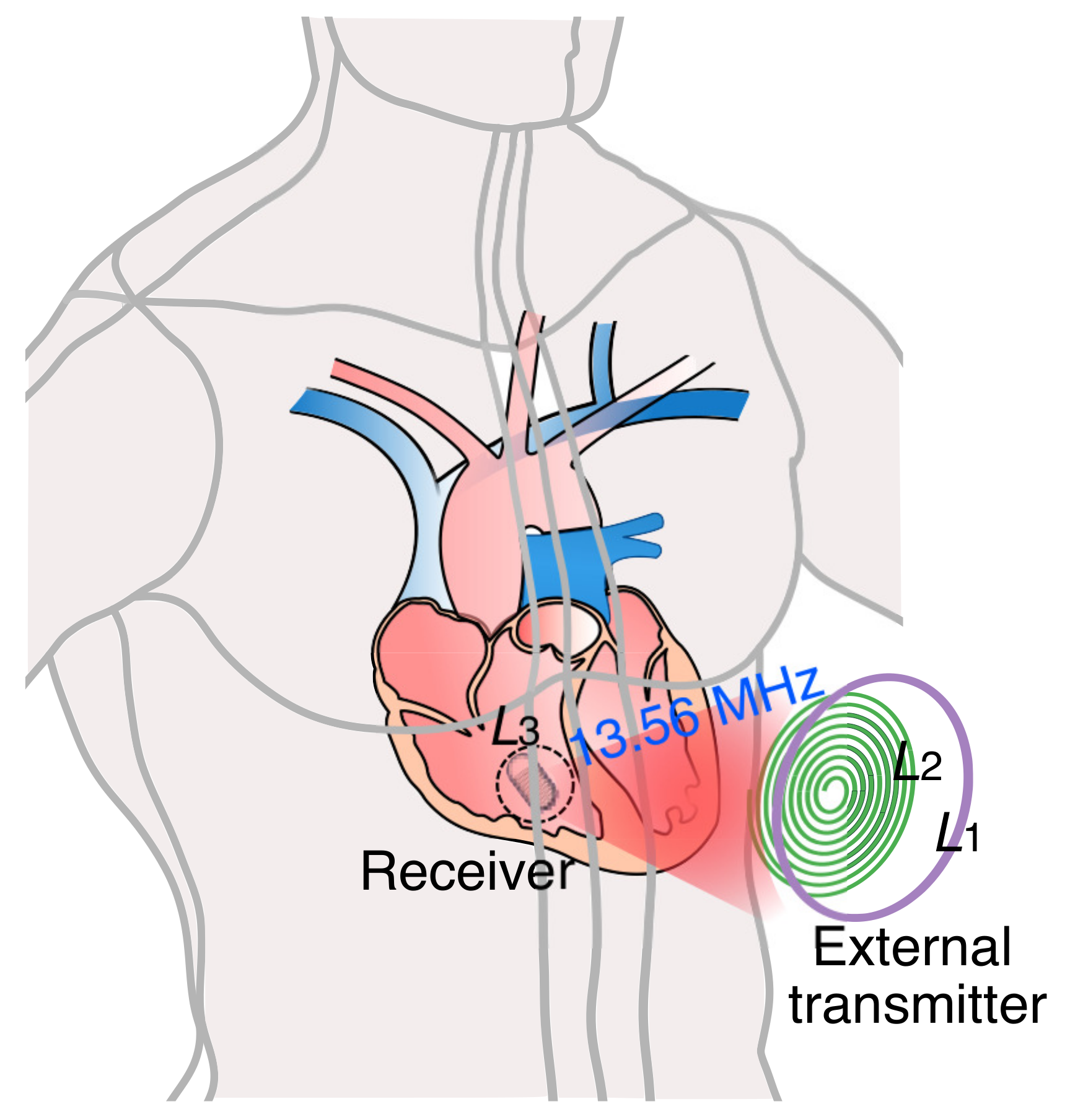
Inductive Power Transfer Link at 13.56 MHz for Leadless Cardiac Pacemakers

1
School of Electronic and Electrical Engineering, College of IT Engineering, Kyungpook National University, Daegu 41566, Korea
2
School of Electronics Engineering, College of IT Engineering, Kyungpook National University, Daegu 41566, Korea
*
Author to whom correspondence should be addressed.
Energies 2021, 14(17), 5436; https://doi.org/10.3390/en14175436
Submission received: 23 July 2021 / Revised: 24 August 2021 / Accepted: 25 August 2021 / Published: 1 September 2021

Abstract

:
Inductive power links are most viable for the long-term powering of cardiac pacemakers. Designing an inductive power link without surpassing the specific absorption rate (SAR) for modern leadless cardiac pacemakers (LCPs) remains a challenging task because of its size and implantation depth. The inductive power link employed in the conventional works is either designed at a high frequency or based on the size, shape, weight, and implantation depth of conventional cardiac pacemakers. Here, a 3-coil inductive power transfer link with a circular transmitter coil and solenoidal receiver coil is designed at 13.56 MHz to provide uninterrupted power to the modern LCPs. Considering the food and drug administration approved term for implant size of modern LCP, the receiver coil is designed with 6 mm diameter and 6.5 mm length. The performance of the link has been verified through simulations and measurements under perfect alignment, lateral and/or angular misalignments, and distance variation between the coils. At a 50 mm horizontal distance between transmitter and receiver coils, the transmission coefficient is −30.9 dB. The maximum simulated average SAR at heterogeneous phantom is 0.30 W/kg, which is lower than the limit set by the Federal Communications Commission for radiation threshold exposure. Experiments conducted on pork’s heart verified the reliability of the simulated results. At a 50 mm distance between the coils, the measured transmission coefficient is −34 dB, and at an input power of 1 W, the power delivered to the load is 0.7 mW.

1. Introduction

Millions of patients with cardiac abnormalities rely on a pacemaker every year, as it delivers electrical impulses to the heart to control abnormal heart rhythms. With continuous improvements in pacemaker technology, the modern leadless cardiac pacemakers (LCPs), about the size of a vitamin capsule, are 6 mm in diameter and 42 mm in length based on food and drug administration (FDA) approved terms for implants [1]. LCP employs a lithium carbon monofluoride battery [2,3,4] as a power source for long-term powering, but it occupies almost 50% of the device, creating a potential demand for wireless power transmission (WPT). Therefore, integrating the WPT system with a rechargeable small-size battery helps in reducing the overall size of the LCP.
Designing the WPT system for a cardiac pacemaker poses challenges as the receiver coil inside the heart has the size, shape, and weight constraints and should be able to minimize the specific absorption rate (SAR) and maximize power transfer efficiency (PTE) and power delivered to the load (PDL) simultaneously. Considering the aforementioned challenges, a significant amount of research works focus on designing a WPT link for a pacemaker. In [5], Campi et al. adopted wireless power transfer systems based on magnetic resonant coupling between the coils to recharge the batteries of the AIMDs. The systems were designed at 300 kHz and 13.56 MHz considering the EMF safety standards to compare the WPT system performances and electric and magnetic (EM) field safety aspects between two industrial, scientific, and medical (ISM) frequencies. The external diameter of the secondary coil is fixed to 17.65 mm in order to fit the dimensions of a generic pacemaker. In [6], Xiao et al. developed a LCC-C compensation circuit for wireless charging system for implantable cardiac pacemakers. Although the designed system at 300 kHz achieves high power transfer through 8 mm pork tissues at high efficiency without harming the human body, the developed wireless charging system can be applied to the modern pacemakers only after modifications as the receiver coil is designed by considering the shape of implantable cardiac pacemaker 44.5 mm × 30.5 mm. In [7], Liu et al. designed a wireless charging system with a double-sandwiched structure for both transmitter and receiver at an operating frequency of 160 kHz. This system provides a stable charging power over 5 W for different types of micro implantable devices and robotics. The prototype of the design is based on the practical size of the conventional cardiac pacemakers. In [8], a transcutaneous energy transmission system is designed for artificial hearts adapting to changing impedance caused by different loading and coupling conditions. The operating frequency is determined to be 600 kHz and the performance is analyzed at different malposition of the coils. In [9], a transcutaneous power regulator is designed at 300 kHz for the artificial heart. The primary and secondary windings of the transcutaneous transformer are positioned outside and inside the human body, respectively, for energy transfer. Though the works presented above use low ISM frequency, their proposed coils are based on the size, shape, weight, and implantation depth of conventional cardiac pacemakers. In [10,11], a WPT link with a conformal implantable antenna is designed for LCP in the midfield band (1.45–1.6 GHz), but according to Federal Communications Commission (FCC), the rate of EM field absorption by tissue of animal/human is high at frequencies above 20 MHz. Designing an efficient WPT link at low frequency considering the size, implantation depth and power requirements of modern LCP is a challenging task.
In this paper, we have designed a 3-coil inductive power link with a solenoidal receiver coil and circular transmitter coil at 13.56 MHz in heterogeneous phantom by considering the size and shape of modern LCP. The capsule-shaped IMDs are preferred to be designed close to a prolate spheroid or a cylinder, and therefore the coils are generally designed in the form of a solenoid [12]. This work adopts a solenoid shape for the receiver coil conforming to the modern LCP device surface. We have considered planar circular shapes for the source and the transmitter coil to maximize the power transfer and provide maximum comfort to the patients in real-time. The heterogeneous phantom is created with layers of skin, fat, muscle, bone, and heart. The solenoidal receiver coil is placed inside the heart layer at a distance of 50 mm from the circular transmitter coil placed above the skin layer. Figure 1 is the schematic representation of our proposed 3-coil inductive power link for powering the LCP in the right ventricle. The performance of the inductive power link is analyzed on the basis of PTE and SAR. As the environmental factors and human activities have a profound impact on the position of the receiver coil, we have also analyzed the PTE with respect to distance variation, lateral and/or angular misalignments. Since the thickness of tissue layers varies from person to person, the performance is also validated under varying tissue compositions.
The remaining sections of the paper are organized as follows: first the proposed 3-coil inductive power link methodology and optimization procedure for attaining maximum PTE are discussed in Section 2. Section 3 presents the performance analysis of the 3-coil inductive power transfer link at heterogeneous phantom under the varying distance between the coils and different orientations of the receiver coil. The safety aspect of the proposed 3-coil inductive power link at 13.56 MHz is also discussed in this section. Fabrication and measurement results are presented in Section 4, followed by the conclusion section.

2. 3-Coil Inductive Power Link Methodology and Optimization Procedure

A 2-coil inductive power link methodology is the most common and widely used methodology to power implantable medical devices. The 2-coil inductive power link achieves a high PTE and PDL only in the near-field regions (≈2 cm) [13,14,15]. For coupling over long distances (≈5 cm), multi-coil inductive power links using 3-coil and 4-coil topologies are usually optimal choices [16,17,18,19]. These links achieve high PTE across larger coupling distances and provide a higher degree of freedom in optimization. Through comprehensive analysis of multi-coil link topologies over wirelessly powered implantable medical devices, 3-coil topology is found to be superior compared with 4-coil topology in terms of PDL [17]. By weighing the advantages and disadvantages of inductive power transfer link topologies, a 3-coil inductive power link topology is adopted in this paper.

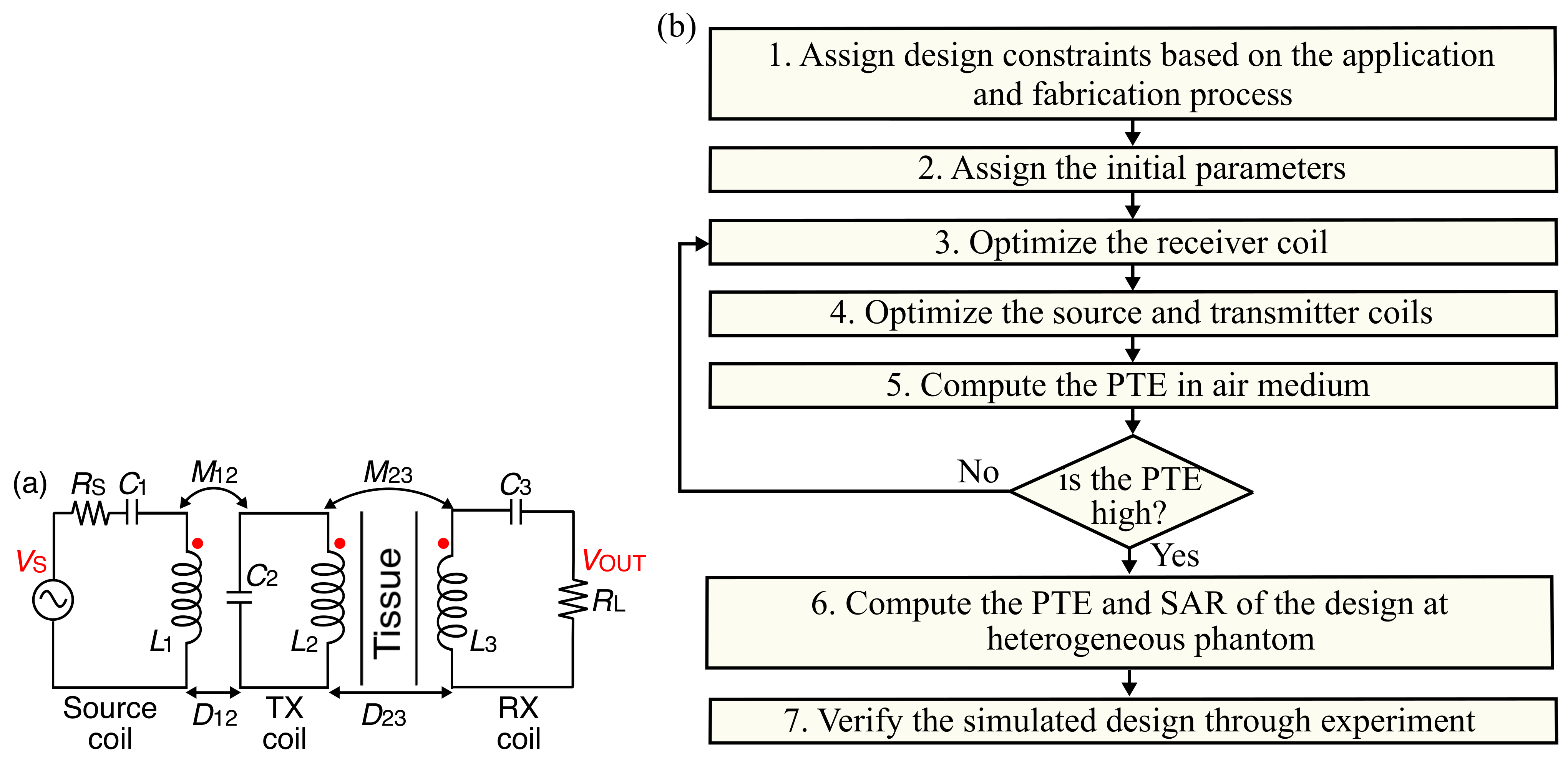
2.1. Equivalent Circuit Model of a 3-Coil Inductive Power Link

In order to design a 3-coil inductive power link, depending on the application, an additional coil and capacitor are either added to the transmitter or receiver of a 2-coil inductive power transfer link [20,21]. The receiver coil used in this work has size and weight constraints as it is placed inside the heart, and therefore this work has the additional resonator on the transmitter side. The simplified equivalent circuit model of a 3-coil inductive power link consisting of source, transmitter, and receiver coils is shown in Figure 2a. For simplicity and consistency purposes, the source coil, transmitter coil, and receiver coil are addressed as L 1 , L 2 , and L 3 , respectively, throughout this work. The efficiency of the 3-coil inductive power link depends on the mutual inductance between L 1 and L 2 ( M 12 ) and L 2 and L 3 ( M 23 ) and Q-factor of the coils. The coupling distance between L 1 and L 2 is denoted by D 12 and the coupling distance between L 2 and L 3 , known as the implantation depth, is denoted by D 23 . In order to acquire a strong M 23 , it is important to achieve a high M 12 as an increase in M 12 eventually increases M 23 . M 12 can be maximized by adjusting D 12 , and the inner and outer diameter of L 1 with respect to L 2 . M 12 and M 23 can be calculated as in Equation (1) [22]:
I m ( Z 12 ) / ω o ; I m ( Z 23 ) / ω o
where Z and ω o = 2 π f denote impedance and resonant frequency of the coils, respectively. The efficiency of the WPT is maximum when L 1 , L 2 , and L 3 are tuned to the resonant frequency, ω o = 1 / L 1 C 1 = 1 / L 2 C 2 = 1 / L 3 C 3 , where C 1 , C 2 , and C 3 are tuning capacitances and L 1 , L 2 , and L 3 are self-inductances. Q-factor of L 1 , L 2 , and L 3 can be obtained as in Equation (2) [23]:
Q i = ω o L i / R i
where i = 1, 2, 3; L i and R i are the inductance and resistance of the coil i, respectively. The efficiency ( η ) in terms of the transmission coefficient ( S 21 ) can be expressed as in Equation (3) [24]:
η = | S 21 | 2 × 100 ( % )

2.2. Optimization Procedure of the Proposed 3-Coil Inductive Power Link

In order to attain optimal coil geometries, a design procedure as shown in Figure 2b is adopted, and a High Frequency Structure Simulator (HFSS) is used to simulate and optimize the L 1 , L 2 , and L 3 . The steps of the design process are as follows:
Step-1:
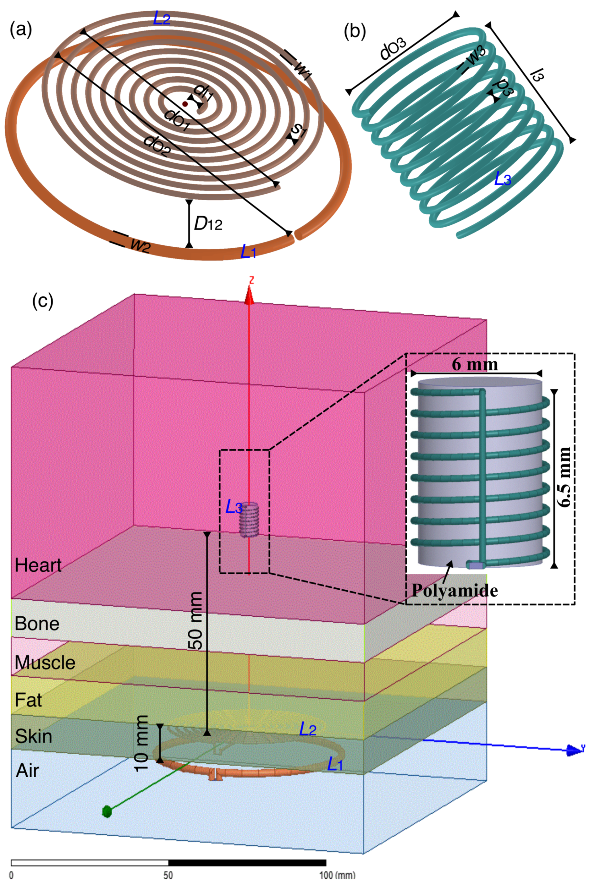
Define the design constraints based on the LCP application. A decision has to be made on the shape and size of the coils. Considering the shape and size of modern LCPs, we have chosen a solenoidal shape receiver coil with a maximum diameter of 6 mm. As L 1 and L 2 lie on the chest, We have considered planar circular shapes to ensure comfort. L 1 , L 2 , and L 3 use copper for winding, and the operating frequency is chosen to be 13.56 MHz.
Step-2:
The parameters of L 1 , L 2 , and L 3 are initialized in this step. The parameters are number of turns (n), wire width (w), the inner diameter of the coil ( d I ), pitch (p), and spacing between the turns (s).
Step-3:
L 3 optimization is carried out in this step. Parametric sweep is performed with respect to w 3 , n 3 , and p 3 to find optimal geometry for L 3 . This way a high Q 3 and self-inductance of L 3 are achieved. The Q 3 can be calculated as in Equation (2).
Step-4:
This step carries out L 1 and L 2 optimization. The parametric sweep of L 1 and L 2 is performed with respect to w 1 , s 1 , d I 1 , n 1 and w 2 , s 2 , d I 2 , and n 2 . This step finds optimal geometries for L 1 and L 2 . It is important to achieve a strong M 12 as increase in M 12 eventually increases M 23 .The higher the value of M 23 , the higher the value of efficiency. M 12 , Q 1 , and Q 2 can be calculated as in Equations (1) and (2).
Step-5:
Evaluate the efficiency between L 2 and L 3 in air medium. D 23 is set to 50 mm. R S and R L are defined in this step. For a low efficiency, the process is iterated from Step-3 till a maximum efficiency is achieved. As mentioned above, maximum efficiency occurs at the resonance frequency, and therefore, the tuning capacitances C 1 , C 2 , and C 3 tune the resonance frequency.
Step-6:
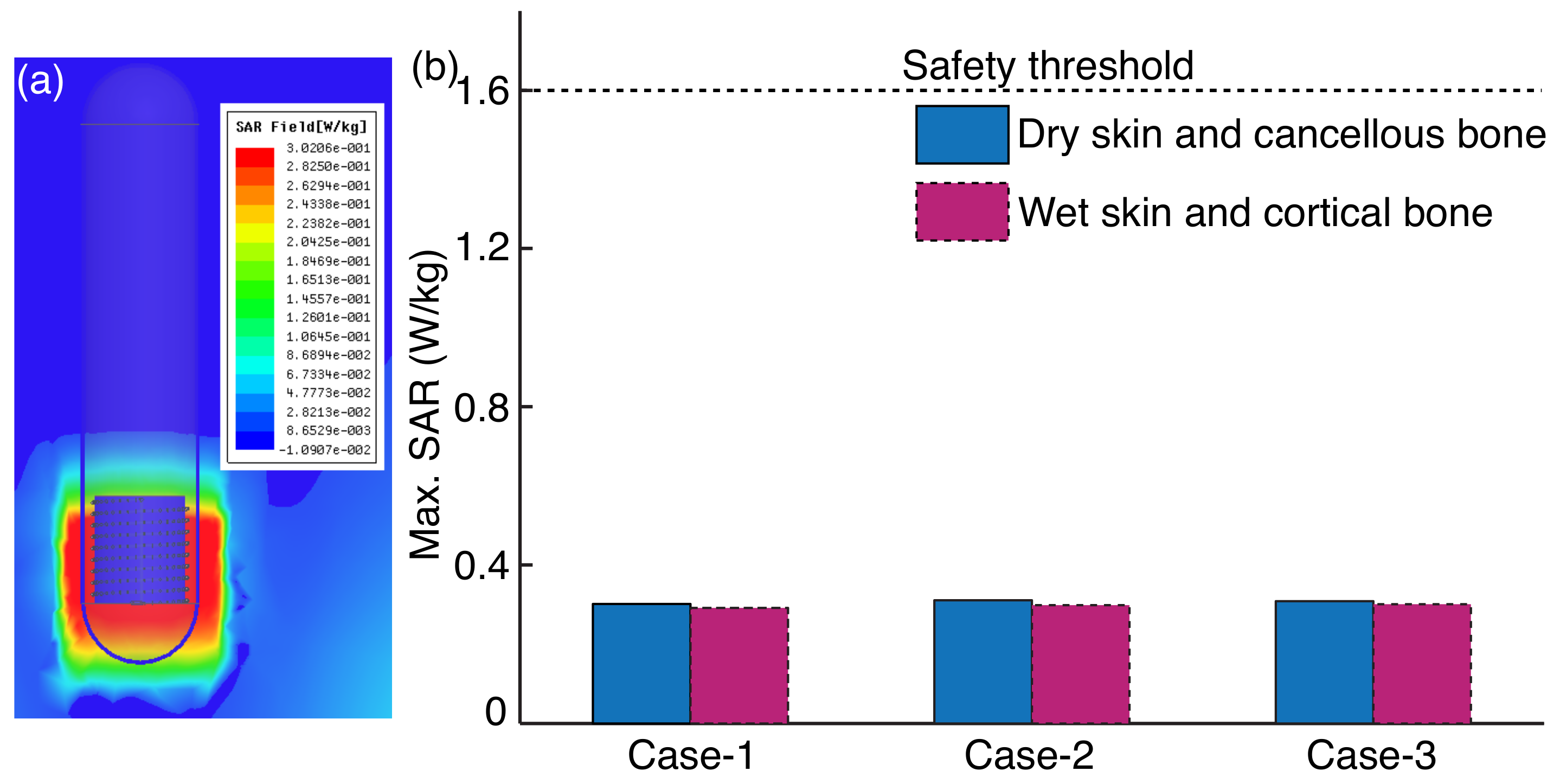
To evaluate the efficiency of the inductive power link in a real environment, the air medium is replaced with a heterogeneous phantom between L 2 and L 3 . The presence of tissue in between the coils shifts the resonance frequency, therefore C 1 , C 2 , and C 3 have to be finely tuned. This step also evaluates the safety aspect of the inductive power link by computing the average SAR.
Step-7:
Finally, the optimal simulated design is experimentally evaluated.

3. Proposed Coil Geometries and Performance Analysis

3.1. External Transmitter Coil and Receiver Coil Geometries

The geometries of L 1 , L 2 , and L 3 obtained after the iterative procedure are shown in Figure 3a,b. As we discussed above, d O 3 is set to 6 mm and l 3 is varied with respect to n 3 , w 3 , and p 3 . Initially, n 3 is set to 8, and to find optimal turns, it is varied from 8 to 12 with respect to w 3 and p 3 . The maximum Q 3 and self-inductance attained with n 3 = 9 are 102 and 268.4 nH, respectively. The weight of L 3 at n 3 = 9 and w 3 = 0.2 mm is 0.05 g. Since the L 3 is lightweight, it perfectly fits the modern LCP device. Though L 1 and L 2 are placed above the chest, it is important to design coils that are compact in size. L 1 and L 2 are optimized simultaneously to maximize M 12 . The M 12 achieved at D 12 = 10 mm is high when compared to M 12 at D 12 = 0 mm. Therefore, the D 12 is fixed to 10 mm. The n 2 is varied in the range of 7 to 10 and considering d O 2 of L 2 , L 1 was initially designed with two turns, but the resulting M 12 is low. Hence, n 1 is set to 1. The achieved Q 2 and self-inductance of L 2 are 610 and 1867.8 nH. The achieved Q 1 and self-inductance of L 1 are 377 and 131.2 nH. Table 1 shows the optimized parameters of L 1 , L 2 , and L 3 at 13.56 MHz.

3.2. Power Transfer Efficiency in Heterogeneous Phantom

We have characterized the heterogeneous phantom with layers of skin (dry), fat, muscle, bone (cancellous), and heart to validate the performance of the inductive power link close to the real-time environment. The heterogeneous phantom is formed with skin, fat, muscle, bone each of 10 mm thickness, and considering the size of the heart in real-time [25], the thickness of the heart layer is considered to be 60 mm. Figure 3c shows L 1 , L 2 , and L 3 geometries in heterogeneous phantom used in the simulation study where L 1 and L 2 lie in the air and L 3 is inside the heart layer. These layers are considered based on the relative permittivity ( ϵ r ), loss tangent ( tan δ ), and conductivity ( σ ) of the body tissue at 13.56 MHz as shown in Table 2. L 3 is simulated in a substrate made of bio-compatible polyamide with ϵ r and tan δ of 4.3 and 0.004 and thickness of 5.5 mm to provide support and allow flexible wounding of L 3 . L 3 here is positioned horizontally with respect to L 2 and L 1 inside the heart layer at D 23 = 50 mm. The resonant frequency of coils is achieved at C 1 = 1 pF, C 2 = 105 pF, and C 3 = 1 pF. The R S and R L across L 1 and L 3 are set to 50 Ω . S 21 and M 23 at D 23 = 50 mm are −30.9 dB and 68.5 nH, respectively, and are highlighted in Figure 4a. The black dashed box in Figure 4b represents S 21 with respect to frequency.
The changes in the biological environment and breathing pattern can cause variation in distance between the coils and misalignment of coils. Therefore, in addition to horizontal alignment, it is important to validate the performance of the inductive power link at varying distances between the coils and under different misalignment conditions. In our previous study [27], different types of misalignments and varied distances between coils are clearly discussed. L 3 lies horizontally with respect to L 1 and L 2 as shown in Figure 5a, and to validate the inductive power link performance for varied D 23 , the L 3 is varied from 45 mm to 55 mm at a step size of 1 mm along the z-axis. The results show that the transmission coefficient decreased gradually with an increase in D 23 . When D 23 = 45 mm and 55 mm, S 21 are −28.8 dB and −32.8 dB, respectively. Figure 4a shows S 21 and M 23 with respect to D 23 and it can be observed that S 21 and M 23 are inversely proportional to D 23 . Figure 4b shows S 21 with respect to D 23 and frequency. Figure 5b,c show L 3 under lateral and angular misalignments. To analyze performance under lateral and angular misalignments, we have considered two notations, namely, Δ and α , where Δ is the displacement and α is the angular rotation. L 3 is laterally displaced along the y-axis from a horizontally aligned position of 0 mm to 20 mm at a step size of 2.5 mm. Figure 6a shows S 21 with respect to lateral displacement and frequency and at the lateral displacement of 20 mm, S 21 is −33.4 dB. L 3 is rotated through angles 15, 30, 45, and 60 relative to L 2 and L 1 to investigate the inductive power link under angular rotation. At 60, the S 21 is −34.5 dB and Figure 6b shows S 21 with respect to angular rotation and frequency. Sometimes the inductive power link suffers from both lateral and angular misalignments, therefore L 3 is investigated under a combination of lateral displacements and angular rotations as shown in Figure 5d. When L 3 is rotated through an angle of 60 along with a lateral displacement of 10 mm, S 21 is −36.6 dB. Figure 6c shows S 21 with respect to frequency and lateral displacements at 60 angular rotation. Figure 6d shows S 21 with respect to angular rotations and/or lateral displacements.
The human body is transparent to frequencies below 20 MHz and therefore maximum permissible exposure limit for frequency is <20 MHz [28,29]. To validate the safety aspects of the designed link, SAR, a basic fundamental exposure limit imposed by FCC on whole-body exposure is computed over a mass of 1 g of tissue. SAR is directly proportional to tissue conductivity ( σ ) and inversely proportional to the density ( ρ ) and can be evaluated using σ | E | 2 / ρ [30,31], where E is the electric field. Currently, the FCC in the US imposes a SAR limit of 1.6 W/kg over 1 g of tissue for the public, and South Korea applies the same standard as the US [32]. The council of the European Union and Japan recommends a value of 2.0 W/kg averaged over 10 g of actual tissue. The maximum simulated average SAR at heterogeneous phantom is 0.302 W/kg and is shown in Figure 7a. The maximum allowable input power can be found from 1 W × 1.6 (W/kg)/0.302 (W/kg) = 5.3 W. The simulated efficiency of the 3-coil inductive power link is ≈0.1%, which implies that selecting an input power in the range of 500–700 mW at the external transmitter side efficiently powers the LCP and only a small fraction of power will be absorbed by the human body.
As discussed earlier in Section 1, the tissue thickness varies with people, therefore the performance of the 3-coil inductive power link on the basis of SAR should be investigated by varying the tissue thickness. To do so, in addition to case-1, which is skin, fat, muscle, bone with a thickness of 10 mm each and 60 mm of heart, we have also considered two other cases. Case-2 is 4 mm of skin, 5 mm of fat, 8 mm of muscle, 10 mm of bone, and 60 mm of heart, and case-3 is 4 mm of skin, 8 mm of fat, 10 mm of muscle, 15 mm of bone, and 60 mm of heart. The maximum simulated average SAR values of case-2 and case-3 are 0.311 W/kg and 0.309 W/kg, respectively. SAR is also validated for wet skin and cortical bone as in Table 2. The average SAR values obtained for wet skin and cortical bone in case-1, case-2, and case-3 are 0.292 W/kg, 0.299 W/kg, and 0.301 W/kg, respectively. The bar graph in Figure 7b shows the studied SAR under case-1, case-2, and case-3 for different skin and bone types. The results show that the SAR is less than the limit set by FCC for all the cases discussed above.

4. Experimental Measurements

The fabrication process is carried out based on the optimized specifications obtained in the simulation environment. A 3D printer (ENDER 3) is used to print the impressions of L 1 , L 2 , and L 3 geometries and copper wire is wound tracing the impressions of these coils. Figure 8a–c show the fabricated L 1 , L 2 , and L 3 , respectively. A dummy capsule case made from PLA as shown in Figure 8d is designed based on the size and shape of the modern LCP device to indicate the area occupied by the L 3 in real-time.
To evaluate the inductive power link performance, we have conducted two types of experiments. The first experiment measures scattering parameters, S 12 using a network analyzer (Rohde Schwartz, ZVH4, Seoul, Korea). This method measures the PTE of the inductive link and not PDL. The second experiment uses an RF power generator (PASCAL-600R2) and oscilloscope (Tektronix, DPO 3032, Seoul, Korea) to measure PDL between the coils. The first experimental setup with L 3 in pork heart immersed with saline solution is shown in Figure 9a. The pork heart is refrigerated and is kept outside in order to attain room temperature before the experiment. L 1 is driven by port-1 of the network analyzer, whereas L 3 is driven by port-2, wherein both the ports have a default impedance of 50 Ω and the overall inductive power link acts as a two-port network. The resonance frequencies of L 1 , L 2 , and L 3 are tuned by capacitances C 1 , C 2 , and C 3 , respectively. At 50 mm horizontal distance, the measured S 21 is −34 dB and is highlighted with a dashed blue box in Figure 9a. The measured S 21 values at 20 mm lateral displacement and 60 angular rotation are −35.1 dB and −36.2 dB, respectively.
The second experiment as shown in Figure 9b uses an RF power generator to transfer an input power of 1 W to L 1 and the PDL at L 3 is measured in terms of voltage and current by an oscilloscope. At D 23 = 50 mm, the achieved PDL is 0.7 mW. The results of the proposed 3-coil inductive power link are compared with the state-of-the-art and are summarized in Table 3. The comparison is made on the basis of the size and shape of the receiver coil, operating frequency, implantation depth, and efficiency. In [5,6], circular receiver coils were designed at 300 kHz and 13.56 MHz by considering the size constraints imposed by conventional cardiac pacemakers (CCP). For powering the leadless pacing system (LPS), a half-cylindrical receiver coil was designed at 13.56 MHz at an implantation depth of 40 mm [33]. Though the system designed produced an efficiency of ≈0.2%, the receiver coil dimension is not compatible with modern LCP. While the efficiency of the designed systems in [10,11] are high when compared to our proposed design, their input powers are restricted to maintain SAR under prescribed safety levels over 1 g and 10 g of tissues. As discussed in Section 3, considering the safety aspects, our proposed link at 13.56 MHz allows a maximum input power of 5 W, though the input power required at the transmitter side for efficient functioning is 500–700 mW.

5. Conclusions

We have designed a 3-coil inductive power transfer link at 13.56 MHz for powering LCPs. Based on FDA approved term for implant size of LCP, the solenoidal receiver coil is designed with 6 mm diameter and 6.5 mm length. The chosen operating frequency is safe, as the SAR evaluated is less than 1.6 W/kg, a limit set by FCC. The performance of the inductive power link is analyzed in a pork heart immersed in saline solution. When the distance between the coils is 50 mm, the S 21 and PDL of the 3-coil inductive power link are −34 dB and 0.7 mW. With an input power of 1 W, the attained PDL is sufficient for powering the LCPs. The performance of the designed link is analyzed under distance variation and different orientations of receiver coil and the PTE did not vary drastically under these conditions. As the lithium carbon monofluoride battery occupies almost 50% of the total modern LCP device, replacing it with a small rechargeable coin battery and our proposed inductive power link can minimize almost 35% of the LCP device length. In the future, in addition to the inductive power link, we intend to design a power receiver chip for recharging coin batteries.

Author Contributions

K.M. and Y.P. conceived, designed the study, gave the theoretical and simulation analysis; K.M. and Y.P. carried out the experiments and wrote the manuscript; K.C. and J.-R.C. provided guidance and key suggestions for the system design and testing. All authors have read and agreed to the published version of the manuscript.

Funding

This research was supported by the Basic Science Research Program through the National Research Foundation of Korea (NRF) funded by the Ministry of Education, Science and Technology (Grant No. NRF2020R1I1A3065961).

Institutional Review Board Statement

Not applicable.

Informed Consent Statement

Not applicable.

Data Availability Statement

Not applicable.

Conflicts of Interest

The authors declare no conflict of interest.

References

  1. Cingolani, E.; Goldhaber, J.I.; Marban, E. Next-generation pacemakers: From small devices to biological pacemakers. Nat. Rev. Cardiol. 2018, 15, 139–150. [Google Scholar] [CrossRef]
  2. Miller, M.A.; Neuzil, P.; Dukkipati, S.R.; Reddy, V.Y. Leadless cardiac pacemakers: Back to the future. J. Am. Coll. Cardiol. 2015, 66, 1179–1189. [Google Scholar] [CrossRef] [PubMed] [Green Version]
  3. Reddy, V.Y.; Exner, D.V.; Cantillon, D.J.; Doshi, R.; Bunch, T.J.; Tomassoni, G.F.; Friedman, P.A.; Estes, N.M., III; Ip, J.; Niazi, I.; et al. Percutaneous implantation of an entirely intracardiac leadless pacemaker. N. Engl. J. Med. 2015, 373, 1125–1135. [Google Scholar] [CrossRef] [PubMed] [Green Version]
  4. Bernard, M.L. Pacing without wires: Leadless cardiac pacing. Ochsner J. 2016, 16, 238–242. [Google Scholar]
  5. Campi, T.; Cruciani, S.; Palandrani, F.; Santis, V.D.; Hirata, A.; Feliziani, M. Wireless power transfer charging system for aimds and pacemakers. IEEE Trans. Microw. Theory Tech. 2016, 64, 633–642. [Google Scholar] [CrossRef]
  6. Xiao, C.; Cheng, D.; Wei, K. An lcc-c compensated wireless charging system for implantable cardiac pacemakers: Theory, experiment, and safety evaluation. IEEE Trans. Power Electron. 2017, 33, 4894–4905. [Google Scholar] [CrossRef]
  7. Liu, C.; Jiang, C.; Song, J.; Chau, K. An effective sandwiched wireless power transfer system for charging implantable cardiac pacemaker. IEEE Trans. Ind. Electron. 2018, 66, 4108–4117. [Google Scholar] [CrossRef]
  8. Fu, Y.; Hu, L.; Ruan, X.; Fu, X. A transcutaneous energy transmission system for artificial heart adapting to changing impedance. Artif. Organs 2015, 39, 378–387. [Google Scholar] [CrossRef] [PubMed]
  9. Chen, Q.; Wong, S.C.; Chi, K.T.; Ruan, X. Analysis, design, and control of a transcutaneous power regulator for artificial hearts. IEEE Trans. Biomed. Circuits Syst. 2009, 3, 23–31. [Google Scholar] [CrossRef] [PubMed]
  10. Das, R.; Yoo, H. Biotelemetry and wireless powering for leadless pacemaker systems. IEEE Microw. Wirel. Compon. Lett. 2015, 25, 262–264. [Google Scholar] [CrossRef]
  11. Das, R.; Yoo, H. A multiband antenna associating wireless monitoring and nonleaky wireless power transfer system for biomedical implants. IEEE Trans. Microw. Theoryand Tech. 2017, 65, 2485–2495. [Google Scholar] [CrossRef]
  12. Mao, S.; Wang, H.; Mao, Z.; Sun, M. A double-helix and cross-patterned solenoid used as a wirelessly powered receiver for medical implants. AIP Adv. 2018, 8, 056603. [Google Scholar] [CrossRef]
  13. Jow, U.-M.; Ghovanloo, M. Design and optimization of printed spiral coils for efficient transcutaneous inductive power transmission. IEEE Trans. Biomed. Circuits Syst. 2007, 1, 193–202. [Google Scholar] [CrossRef]
  14. Mutashar, S.; Hannan, M.A.; Samad, S.A.; Hussain, A. Design of spiral circular coils in wet and dry tissue for bio-implanted micro-system applications. Prog. Electromagn. Res. 2013, 32, 181–200. [Google Scholar] [CrossRef] [Green Version]
  15. Mutashar, S.; Hannan, M.A.; Samad, S.A.; Hussain, A. Analysis and optimization of spiral circular inductive coupling link for bio-implanted applications on air and within human tissue. Sensors 2014, 14, 11522–11541. [Google Scholar] [CrossRef] [PubMed] [Green Version]
  16. RamRakhyani, A.K.; Mirabbasi, S.; Chiao, M. Design and optimization of resonance-based efficient wireless power delivery systems for biomedical implants. IEEE Trans. Biomed. Circuits Syst. 2010, 5, 48–63. [Google Scholar] [CrossRef] [PubMed]
  17. Kiani, M.; Jow, U.-M.; Ghovanloo, M. Design and optimization of a 3-coil inductive link for efficient wireless power transmission. IEEE Trans. Biomed. Circuits Syst. 2011, 5, 579–591. [Google Scholar] [CrossRef] [PubMed] [Green Version]
  18. Sample, A.P.; Meyer, D.T.; Smith, J.R. Analysis, experimental results, and range adaptation of magnetically coupled resonators for wireless power transfer. IEEE Trans. Ind. Electron. 2010, 58, 544–554. [Google Scholar] [CrossRef]
  19. Khan, S.R.; Choi, G. Analysis and optimization of four coil planar magnetically coupled printed spiral resonators. Sensors 2016, 16, 1219. [Google Scholar] [CrossRef] [PubMed] [Green Version]
  20. Zhong, W.X.; Zhang, C.; Liu, X.; Hui, S.Y.R. A methodology for making a three-coil wireless power transfer system more energy efficient than a two-coil counterpart for extended transfer distance. IEEE Trans. Power Electron. 2014, 30, 933–942. [Google Scholar] [CrossRef]
  21. Mirbozorgi, S.A.; Gosselin, B.; Sawan, M. A transcutaneous power transfer interface based on a multicoil inductive link. IEEE EMBS 2012, 1659–1662. [Google Scholar]
  22. Bagheri, A.; Erfanian, A.; Abrishamifar, A. A Systematic Methodology for Optimal Design of Wireless Power Transfer System Using Genetic Algorithm. Energies 2020, 13, 383. [Google Scholar] [CrossRef] [Green Version]
  23. Ohira, T. What in the World Is Q? IEEE Microw. Mag. 2016, 17, 42–49. [Google Scholar] [CrossRef]
  24. Nair, V.V.; Choi, J.R. An efficiency enhancement technique for a wireless power transmission system based on a multiple coil switching technique. Energies 2016, 9, 156. [Google Scholar] [CrossRef] [Green Version]
  25. Betts, J.G.; Young, K.A.; Wise, J.A.; Desaix, P.; Johnson, J.E.; Korol, O.; Kruse, D.; Poe, B.; Womble, M.; DeSaix, P.; et al. Anatomy &amp Physiology: Openstax College; Rice University: Houston, TX, USA, 2013. [Google Scholar]
  26. Available online: http://niremf.ifac.cnr.it/tissprop/htmlclie/htmlclie.php (accessed on 15 March 2021).
  27. Palagani, Y.; Mohanarangam, K.; Shim, J.H.; Choi, J.R. Wireless power transfer analysis of circular and spherical coils under misalignment conditions for biomedical implants. Biosens. Bioelectron. 2019, 141, 111283. [Google Scholar] [CrossRef] [PubMed]
  28. Gabriel, C.; Gabriel, S.; Corthout, Y.E. The dielectric properties of biological tissues: I. Literature survey. Phys. Med. Biol. 1996, 41, 2231–2249. [Google Scholar] [CrossRef] [PubMed] [Green Version]
  29. Christ, A.; Douglas, M.G.; Roman, J.M.; Cooper, E.B.; Sample, A.P.; Waters, B.H.; Smith, J.R.; Kuster, N. Evaluation of wireless resonant power transfer systems with human electromagnetic exposure limits. IEEE Trans. One Compat. 2012, 55, 265–274. [Google Scholar] [CrossRef]
  30. Jia, Y.; Mirbozorgi, S.A.; Wang, Z.; Hsu, C.-C.; Madsen, T.E.; Rainnie, D.; Ghovanloo, M. Position and orientation insensitive wireless power transmission for enercage-homecage system. IEEE Trans. Biomed. Eng. 2017, 64, 2439–2449. [Google Scholar] [CrossRef]
  31. PDutta, K.; Jayasree, P.V.Y.; Baba, V.S.S.N.S. Sar reduction in the modelled human head for the mobile phone using different material shields. Hum. Centric Comput. Inf. Sci. 2016, 6, 3. [Google Scholar]
  32. Available online: https://www.fcc.gov/general/specific-absorption-rate-sar-cellulartelephones (accessed on 5 January 2021).
  33. Abiri, P.; Abiri, A.; Packard, R.R.S.; Ding, Y.; Yousefi, A.; Ma, J.; Bersohn, M.; Nguyen, K.-L.; Markovic, D.; Moloudi, S.; et al. Inductively powered wireless pacing via a miniature pacemaker and remote stimulation control system. Sci. Rep. 2017, 7, 6180. [Google Scholar] [CrossRef]
Figure 1. Schematic overview of 3-coil inductive power link for powering LCP in right ventricle.
Energies 14 05436 g001
Figure 2. (a) Lumped circuit model of the 3-coil inductive power link. (b) The 3-coil inductive power link design procedure.
Energies 14 05436 g002
Figure 3. (a) Circular L 2 and L 1 . (b) Solenoidal L 3 . (c) 3-coil inductive power link in heterogeneous phantom in simulation study.
Energies 14 05436 g003
Figure 4. (a) S 21 and M 23 vs. D 23 . (b) S 21 vs. D 23 vs. frequency, dashed black box represents S 21 at resonant frequency of 13.56 MHz where D 23 = 50 mm.
Energies 14 05436 g004
Figure 5. (a) L 3 at horizontal alignment. (b) L 3 displaced by distance Δ along y-axis. (c) L 3 tilted at an angle α along negative y-axis. (d) L 3 displaced by distance Δ along y-axis and tilted at an angle α along negative y-axis.
Energies 14 05436 g005
Figure 6. (a) S 21 vs. lateral displacement vs. frequency. (b) S 21 vs. angular rotation vs. frequency. (c) S 21 vs. lateral displacement vs. frequency at 60angular rotation. (d) S 21 vs. combination of lateral and angular orientations.
Energies 14 05436 g006
Figure 7. (a) The maximum simulated average SAR. (b) SAR values at varied skin and bone types for case-1, case-2, and case-3.
Energies 14 05436 g007
Figure 8. (a) Circular L 1 with diameter of 62 mm. (b) Circular L 2 with diameter of 53 mm. (c) Solenoid L 3 with diameter and length of 6 mm × 6.5 mm. (d) L 3 enclosed by a transparent dummy 3D capsule case.
Energies 14 05436 g008
Figure 9. (a) Experimental setup for measuring transmission coefficient. (b) Experimental setup for measuring PDL.
Energies 14 05436 g009
Table 1. 3-Coil inductive power link specifications at 13.56 MHz.
ParameterSymbol L 1 L 2 L 3
Inductance (nH)L131.21867.8268.4
Q-FactorQ377610102
Outer diameter (mm) d O 62536
Inner diameter (mm) d I 584.25.6
Length (mm)l--6.5
Number of turnsn199
Width (mm)w210.2
Spacing (mm)s-1.6-
Pitch (mm)p--0.5
Weight (g)---0.05
Distance (mm) D 12 = 10 D 23 = 50
Type of wire Copper
Frequency (MHz) 13.56
Mutual Inductance (nH) M 12 = 141.2
M 23 = 68.5
S 21 (dB) −30.9
Table 2. Dielectric properties of biological tissues at 13.56 MHz [26].
Tissue TypeRelative Permittivity ( ϵ r )Loss Tangent tan δ Conductivity ( σ )
Air1.00.00.0
Skin (Dry)2851.100.23
Skin (Wet)1772.870.38
Fat11.83.400.03
Muscle1386.010.62
Bone59.32.870.12
(cancellous)
Bone30.51.970.04
(cortical)
Heart2392.910.52
Table 3. Comparison with conventional works.
Publication2016 [5]2018 [6]2017 [33]2015 [10]2017 [11]This Work
Type of deviceCCPCCPLPSLCPLCPLCP
Receiver coilCircularCircularHalfSolenoidConformalSolenoid
shape cylindrical spiral
Receiver coil35.644.5 × 30.53 × 159 × 206 × 406 × 6.5
size (mm)
Operating300 kHz &300 kHz13.56 MHz1.5 GHz1.5 GHz13.56 MHz
frequency13.56 MHz
Distance (mm)10 & 101040555550
MediumSalinePorkPigPork heartPork heartPork heart
Efficiency (%)78 & 8978.4≈0.20.580.3≈0.1
CCP—conventional cardiac pacemaker, LPS—leadless pacing system, and LCP—leadless cardiac pacemaker. The conformal spiral receiver coil and solenoid receiver coil size are represented in diameter × length.
Publisher’s Note: MDPI stays neutral with regard to jurisdictional claims in published maps and institutional affiliations.

