Article

Development of a Smart Energy Community by Coupling Neighbouring Community Microgrids for Enhanced Power Sharing Using Customised Droop Control

1
School of Electrical and Electronic Engineering, Technological University Dublin, D07 EWV4 Dublin, Ireland
2
École Centrale School of Engineering, Mahindra University, Hyderabad 500043, India
*
Author to whom correspondence should be addressed.
Energies 2021, 14(17), 5383; https://doi.org/10.3390/en14175383
Submission received: 29 July 2021 / Revised: 27 August 2021 / Accepted: 29 August 2021 / Published: 30 August 2021

Abstract

:
This article aims to develop a smart isolated energy community (EC) by coupling the neighbouring rural community microgrids (CMGs) with enhanced droop control for efficient power sharing. This recommended solution employs a power management (PM) based droop-control to enable independent neighbouring CMGs to share power on an available basis by not constraining CMG inverters to equal power sharing. During the grid-connected mode, the droop control may have different power setpoints of each CMG. However, during the standalone mode of operation, the power setpoint should be defined according to their power rating and availability to maintain the system stability. In this article, a PM strategy is developed to maintain the power setpoints of the autonomous CMGs. An improper selection of power setpoints in autonomous CMG can raise the DC link voltage to an unmanageable value and can cause an inadvertent shutdown of CMG. The suggested PM-based droop control enables the CMG inverter not to restrict the inverter to equal power share but to distribute its active power as available in an asymmetric way, if required. The dynamic performance of the proposed coupled system incorporated with two remote isolated CMGs is investigated in a MATLAB environment. Further, a laboratory prototype of the proposed system has been developed using a LabVIEW-based sbRIO controller to verify the efficacy of the proposed approach.

1. Introduction

The high penetration of renewable energy sources (RES) in rural ECs are the backbone of the European Strategy (2018/2001/EU, RED II) [1] towards a clean and low carbon society. EC is the modern recognition of smart communities, where everyone from energy policymakers to customers plays a vital role in achieving sustainable living for society [2,3]. Any legal body, such as an association/community, a cooperative, a partnership, a non-profit organization, or a small/medium-sized business, can form an energy community. It makes it easier for its residents to pool their resources and invest in energy assets in collaboration with neighbouring community participants. As a result, the energy communities can function as a single entity and access all appropriate energy markets on an equal footing with other market participants, contributing to a more decarbonized and flexible energy system [4,5].
ECs allow the neighboring CMGs to work together to achieve their own and collective economic, environmental, and social goals while also helping to decarbonize the energy system. Maintaining generation demand balance in an EC is a critical task for a system/community operator. This requires maintaining a certain level of flexibility in the system, which forms an inevitable system service requirement. In these isolated CMGs, the intermittent nature of dispersed energy sources, along with load uncertainties, might induce a power mismatch, resulting in unwanted frequency and voltage variation. Implementation of intelligent demand response techniques or installing micro storage devices (such as batteries, supercapacitors (SC), flywheels etc.,) [6,7] and diesel generators can provide the required power to avoid this power scarcity. However, load shedding is still necessary if there is insufficient power in a CMG. Critical community infrastructures have to be connected with the power supply for the sustainable development of the community during any contingency. The coupling of neighboring isolated CMGs is economical and technically more feasible for any power exchange during any contingency.
Parallel operation of the inverters is the key issue of standalone coupled CMGs for operational power-sharing and maintaining the voltage and frequency within acceptable limits during dynamic load and generation change. The coupling of MGs was introduced in [8], and thereafter a lot of research has been conducted in this area [9,10,11,12,13]. It has been shown that proper utilization of available power sources among the neighbouring MGs during the coupling situation can solve the power deficiency more efficiently and effectively. Load sharing between the inverters can be achieved through either communication channel-based PM technique or using conventional droop control. A dynamic multi-criterion decision-making system-based overload management technique is presented in [11]. A master-slave control [9] and small-signal stability-based control [14] for coupling microgrids are also proposed. The coupling of hybrid (combination of different RESs) MGs and their coupling issues are also elaborately discussed in [15,16,17,18,19]. Decentralized active power control with a hierarchical control technique is proposed in [20] for the connection of battery energy storage systems (BESS) with photovoltaics (PV) units. The bus signaling method controls the power regulation among the MG elements. Moreover, an optional secondary control technique is proposed for frequency restoration.
Complexity in control topology, computational burden, and lack of reliability due to a communication network is the main drawback in the above-proposed topologies. Note that all of these coupling techniques and their control topologies are incorporated with some communication technique, or there is an availability of a large power grid.
In order to overcome the drawbacks of the communication channel, the conventional droop control method is employed to control the load sharing between the inverters. Droop control-based clustering topology is also well discussed in recent pieces of literature [16,21,22]. A complete review of coupling/clustering MGs and their associated issues are presented in [23,24,25]. Virtual impedance-based droop control [26], adaptive droop control [27], and robust droop control [28] are also well discussed in recent literature. These improved control techniques are implemented to overcome specific challenges such as improved harmonic power-sharing, good dynamic response, good transient response, stability improvement, accurate reactive power-sharing, improved frequency, and voltage regulation. To achieve these improvements, sometimes these control techniques compromise the accuracy of active power-sharing, reliability, stability etc. Sometimes there is a practical difficulty to implement the complicacy [29].
Different PM strategies incorporating renewable energy sources and storage devices are also proposed in [30,31]. To improve BESS usage in a PV-BESS based hybrid autonomous system, Mahmood, H et al. [30,31] developed a power management system based on an equivalent consumption minimisation technique. In all the cases, the PM strategy is developed based on the state of charge (SoC) of BESS and the active/reactive power control is achieved through the conventional droop control. Erdinc et al. [6] developed a load sharing algorithm for a fuel cell/SC hybrid system based on fuzzy logic control and a PM technique for a fuel cell/battery/SC hybrid system. The control solutions described in these research papers are tailored to a single unit MG that functions as a standalone power source from a control standpoint. Therefore, they cannot be deployed in multiple unit MGs without modification.
The majority of the above techniques can only accommodate two of the symmetrical or hybrid distributed generation (DG) units in a MG. Most of them are connected to the main grid power supply. In the most published literature, symmetrical droop units have been considered, where equal power-sharing has been achieved. But in practical cases, due to the intermittency of DG sources and different power ratings of neighbouring CMGs, equal power-sharing can restrict proper utilization of coupling advantages. In asymmetric power-sharing, inappropriate droop gain can lead the standalone CMG to an unstable condition and considerably deviate the system voltage and frequency. To reckon with the above issues, this research article has considered the following enhanced features:
  • A well-defined control strategy where symmetric and asymmetric (if required) power-sharing can be achieved through a PM-based droop control in order to couple the neighbouring CMGs more efficiently. The proposed PM strategy defines the reference power setpoints for the conventional droop control.
  • An enhanced frequency regulation method without using a secondary controller. The power flow between the CMGs is controlled keeping the frequency within an allowable range. As the considered system is static and standalone, the proposed PM-based droop control helps to maintain the system frequency in an acceptable range.
  • A validated test of proposed controller by developing laboratory scale CMGs.
In order to cover the proposed research, the rest of this article is organized as follows:
  • The suggested PM-based droop control technique, as well as the proposed system configuration, are introduced in Section 2.
  • The control of CMG inverters using PM-based droop control is discussed in Section 3.
  • Section 4 uses simulated and real-time data in Section 5 to demonstrate the effectiveness of the proposed controller.
  • Finally, Section 6 draws the summary of the most critical contribution presented here.

2. System Configuration and Proposed Droop Control for Power Sharing

Static generators, such as PV based CMGs, have been considered in the proposed system architecture to build a smart energy community. The intermittent nature of PV power generation poses a significant challenge to the widespread adoption of PV systems in islanded CMGs in the absence of storage devices. Furthermore, frequency regulation is a great challenge in this kind of complete static generation. In order to maintain a power balance in isolated CMGs, the deployment of BESS is necessary to compensate for the intermittent nature of PV units. Battery systems, on the other hand, have limited power ratings, capacities, and charging scenarios, all of which are determined by the battery SoC. As a result, for effective and efficient energy generation, the functioning of the PV and battery units must be coordinated. Installation of BESS and incorporation with PV is not economical sometimes due to the low lifecycle of BESS (compared to PV, which could have to replace three times in an entire PV plant life cycle) and high installation cost [32]. Considering the above-stated issues, two CMGs are considered for coupling, and between them in only one community the PV systems are connected with a BESS through a bi-directional DC/DC converter, as indicated in Figure 1. In both the CMGs PV panels are connected through a DC/DC converter, and the local AC loads are supplied through a DC/AC inverter. Both the CMGs are operated only in isolated mode. In this scenario, droop control is considered for required power-sharing.
The conventional voltage and frequency droop control equations for each inverter of MGs are-
ω = ω * k ω ( P P * )
V = V * k V ( Q Q * )
where kω and kV are the frequency and voltage control droop co-efficient; ω* and V* are the nominal value of frequency and voltage, respectively.
Usually, in the grid-connected mode, the grid provides the rigid voltage and frequency support, and it specifies the active and reactive power setpoints for the MGs. However, suppose there is any significant deviation from the setpoint value. In that case, the MG controller needs to disconnect/connect some load/sources as the connecting inverters are operating in a grid following mode. However, in the case of isolated CMG operation, the voltage and frequency are set to their nominal value, and the power setpoints play an essential role in maintaining the voltage and frequency. In the proposed droop control, a PM topology is adopted in order to maintain the frequency and voltage within an acceptable range. The droop slopes are calculated accordingly to maintain the stable mode of operation during coupling.
As shown in Figure 2, the droop control topology consists of two inverters for a grid-connected and standalone mode of operation. For example, as the stiff grid controls the frequency in grid-connected mode, the two inverters generate different power (P1Grid & P2Grid) in the same frequency, ω0. But in a standalone/isolated mode of operation, the system frequency starts to diverge from the nominal value. It is imperative to define an acceptable frequency region for the stable mode of operation in this situation. For standalone mode of operation, the acceptable frequency range is 50 Hz ± 2 Hz [33,34]. After reaching a stable frequency (ωisolated), both the inverters produce P1 and P2 for the same droop coefficient. Now, the steady-state standalone frequency can be calculated as-
ω i s o l a t e d = ω * k ω 1 P 1 + k ω 1 P 1 * = ω * k ω 2 P 2 + k ω 2 P 2 *
As the droop coefficients (kω1 = kω2) are the same so,
P 1 = P 1 * + P 2 P 2 *
As the total load power (PLoadtotal) is supplied by the two inverters (PLoadtotal = P1 + P2), further the steady-state isolated frequency can be calculated as:
ω i s o l a t e d = ω * k ω 2 ( P L o a d t o t a l P 1 * P 2 * )
So, it can be noted that the isolated frequency depends on the total load connected to the system and the power set point for the droop control. For equal power-sharing from both the inverter, the power setpoints (P1* & P2*) should be equal.
In this steady-state islanded frequency, the generated power from both the inverter can be calculated as:
P 1 = 1 2 ( P L o a d t o t a l + P 1 * + P 2 * )
P 2 = 1 2 ( P L o a d t o t a l + P 2 * P 1 * )
A critical case study where power transfer from one CMG to another has been illustrated in Figure 2. When the total load demand is less than the difference between two power set points of the inverters, i.e., P L o a d t o t a l < | P 1 * P 2 * | , the power can be drawn from one CMG to another. In this condition, one of the inverters will import the power (in Figure 2, the connecting inverter of CMG2 is importing power). The imported power will cause to upsurge in the DC link bus voltage. So, extra power can be utilized to fulfil the load demand in another CMG to maintain a stable mode of operation. The BESS will further supply/import the power in case of any critical power balance situation.

3. CMG Inverter Control Strategy with PM Based Droop Control

Towards further analysis, the suggested static generating configuration, i.e., PV generation, as shown in Figure 1 is expanded to illustrate the inverter control method in Figure 3. Each CMG includes the main energy source (PV), voltage source inverter and the LCL filter as well as local loads. PV is linked with BESS via a bi-directional converter in one of the CMG units. During any contingencies, both CMGs are interconnected by a switch.
A conventional standalone single-phase system is considered to make the system configuration more realistic for rural area connections. The implemented inverter control technique is shown in Figure 3, where one side of the inverter control is depicted elaborately. On the other side, the same control technique is adopted during standalone operation. The proposed inverter control technique can regulate the system voltage and frequency in the isolated mode without connecting to another synchronizing converter/generator. In this proposed control system, the active power delivered by the converter is the function of system frequency. The power-sharing of the converter is achieved by implementing the communication less droop control, where a PM technique (as shown in Figure 4) is adopted to define the power setpoints (P1* & P2*) of the inverters of the CMGs.
Further, the voltage and frequency droop co-efficients are adjusted in such a way (using Equations (3)–(7)) that the voltage and frequency always remain in the allowable range. Figure 3 shows the detailed control topology of the CMG1 inverter when operating in standalone mode. The operation of the CMG2 inverter is controlled by the maximum power point controller/power management controller, which defines the power reference values for the inverter. Additionally, the CMG1 inverter generates the voltage reference for the CMG2 inverter in the coupled mode of operation.
The power setpoint calculation in an allowable stable frequency is achieved by using the power management algorithm. Starting from the normal operating condition, several constraints can give rise to challenging and intriguing situations for interconnected power flow requirements between the two CMG, managing the voltage and frequency regulation. It is also essential to identify strategic conditions where the BESS can be suitably recharged. The following five modes are believed to have captured all of these possibilities. Control algorithms have been devised for the uninterrupted operation of this interconnected scheme as far as possible, except for faulty conditions. The implementation of the control technique for the proposed coupled CMGs is shown in Figure 3. SW1 is the breaker switch that is used to connect the neighbouring CMGs. The PM strategy and the coupling control scheme are provided in Figure 4. The working principle during the different modes of operations is elaborately discussed through five modes in this section.

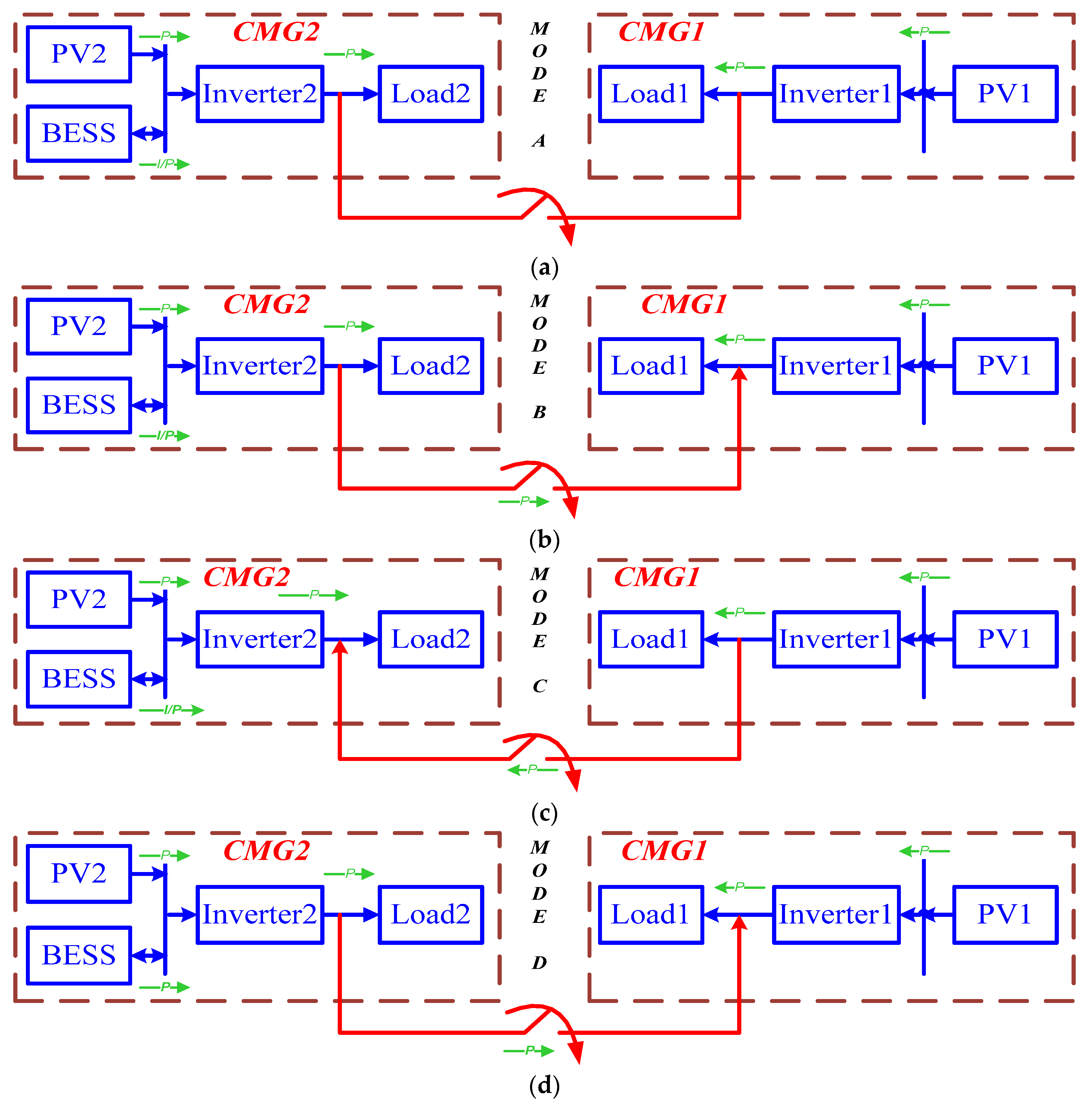
3.1. Independent CMG Operation

This mode of operation is assumed for the isolated mode of operation before connecting two neighbouring CMGs for available power-sharing. In this mode of operation, both the CMG contributes the required local loads by maintaining the desired frequency. Figure 5a shows that both the CMGs are operating separately, and the breaker switch SW1 remains in the ‘off’ condition.

3.2. CMG1 Is Overloaded in Inter-Connected Mode

In this mode of operation, the shortage power in CMG1 can be exported from CMG2 if there is any excess power in CMG2 by switching on the breaker switch SW1. The power calculation can be conducted in PM block, and to maintain the stable allowable frequency, the power setpoint and the droop gain values should be updated accordingly. The power flow diagram in this condition is shown in Figure 5b.

3.3. CMG2 Is Overloaded in Inter-Connected Mode

In this case as shown in Figure 5c, power can be drawn from the BESS to meet the local load demand. Otherwise, the power can be drawn from the CMG1 (if there is any excess power) to utilize the renewable energy generation in CMG1 fully. In the proposed power calculation algorithm shown in Figure 4, if there is any excess power in CMG1, it can be imported to CMG2 first, and BESS fulfils further deficiency (if any).

3.4. Both CMGs Are Overloaded in Inter-Connected Mode

In this condition, BESS is used to meet the total load demand. The power flow diagram is shown in Figure 5d. In the worst-case scenario, when BESS and both the PV plant cannot supply the local loads, the CMG coupling connection can be revoked, and the load shedding technique can be adopted to maintain system stability. It should be noted that the load shedding techniques are not in the scope of this research.

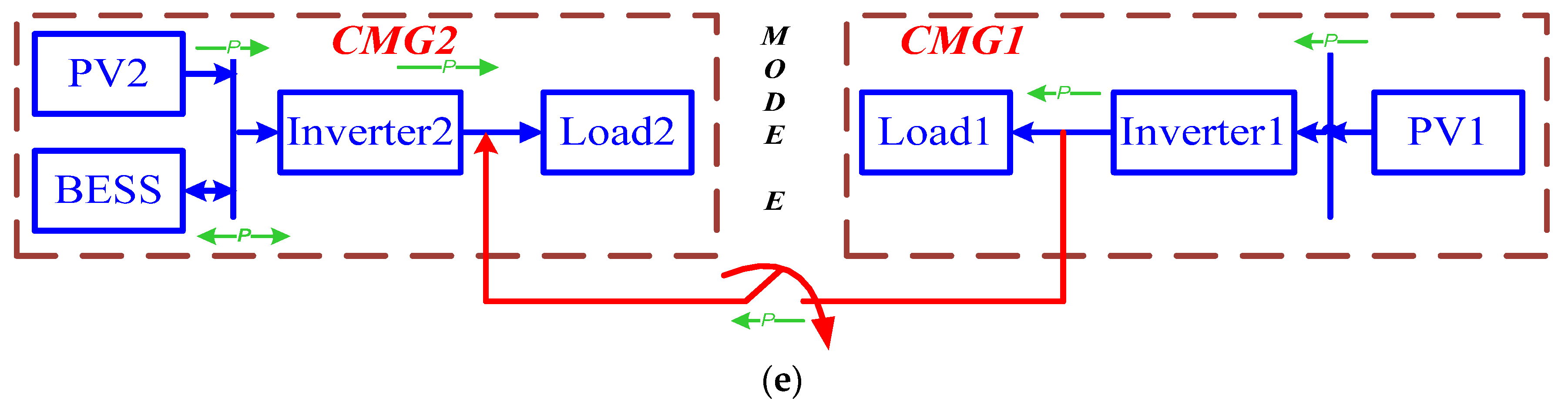
3.5. Both the CMGs Are Underloaded in Inter-Connected Mode

In this condition, both the CMGs can be used to recharge the BESS. In this condition, the complexity in the control strategy can be increased. So, in order to keep it simple, the full produced power of CMG1 is utilized to meet the local load demand in CMG1 and CMG2. The power produced in CMG2 is used to recharge the BESS and to meet the remaining load power demand. The power flow diagram is shown in Figure 5e.

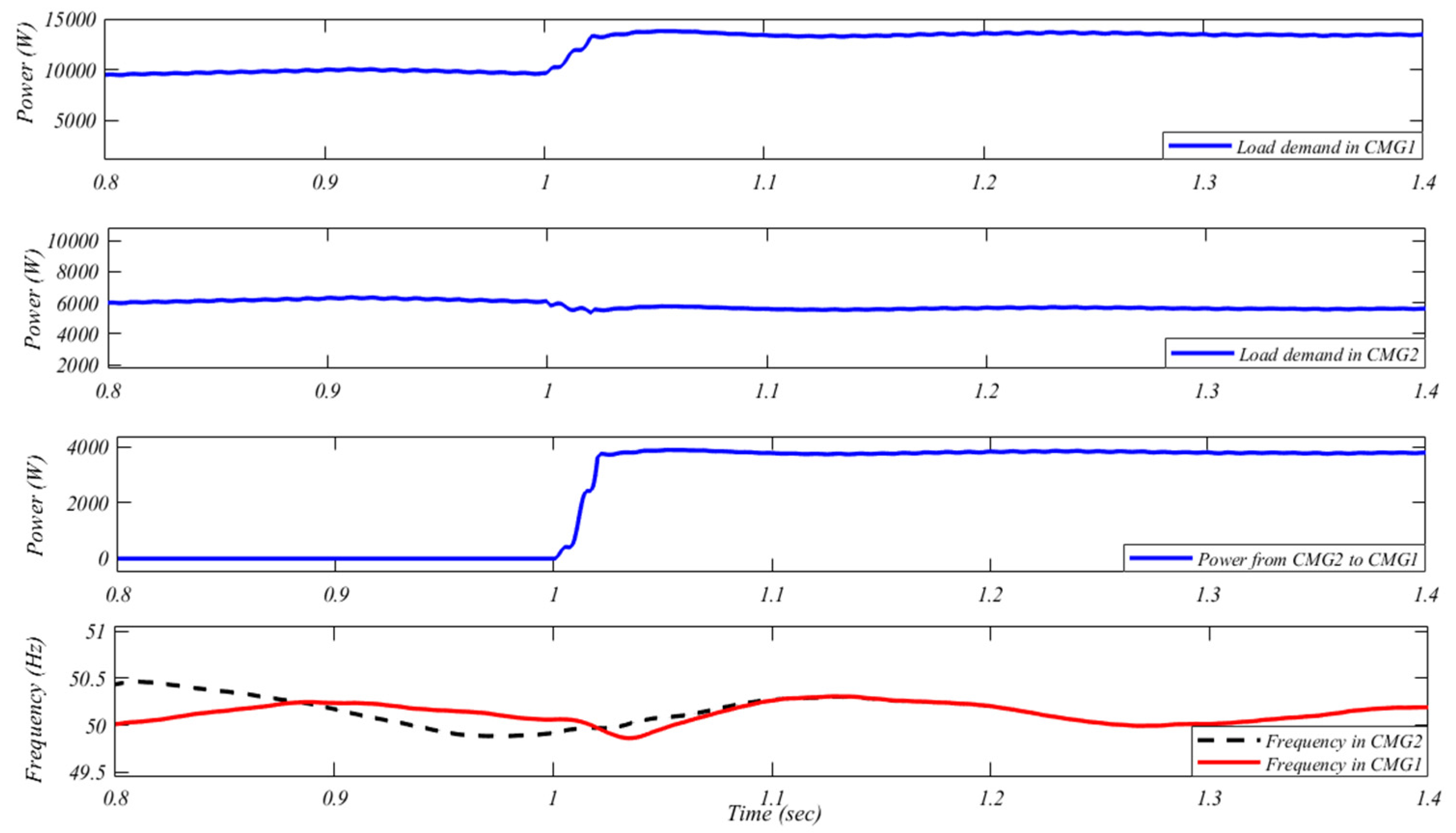
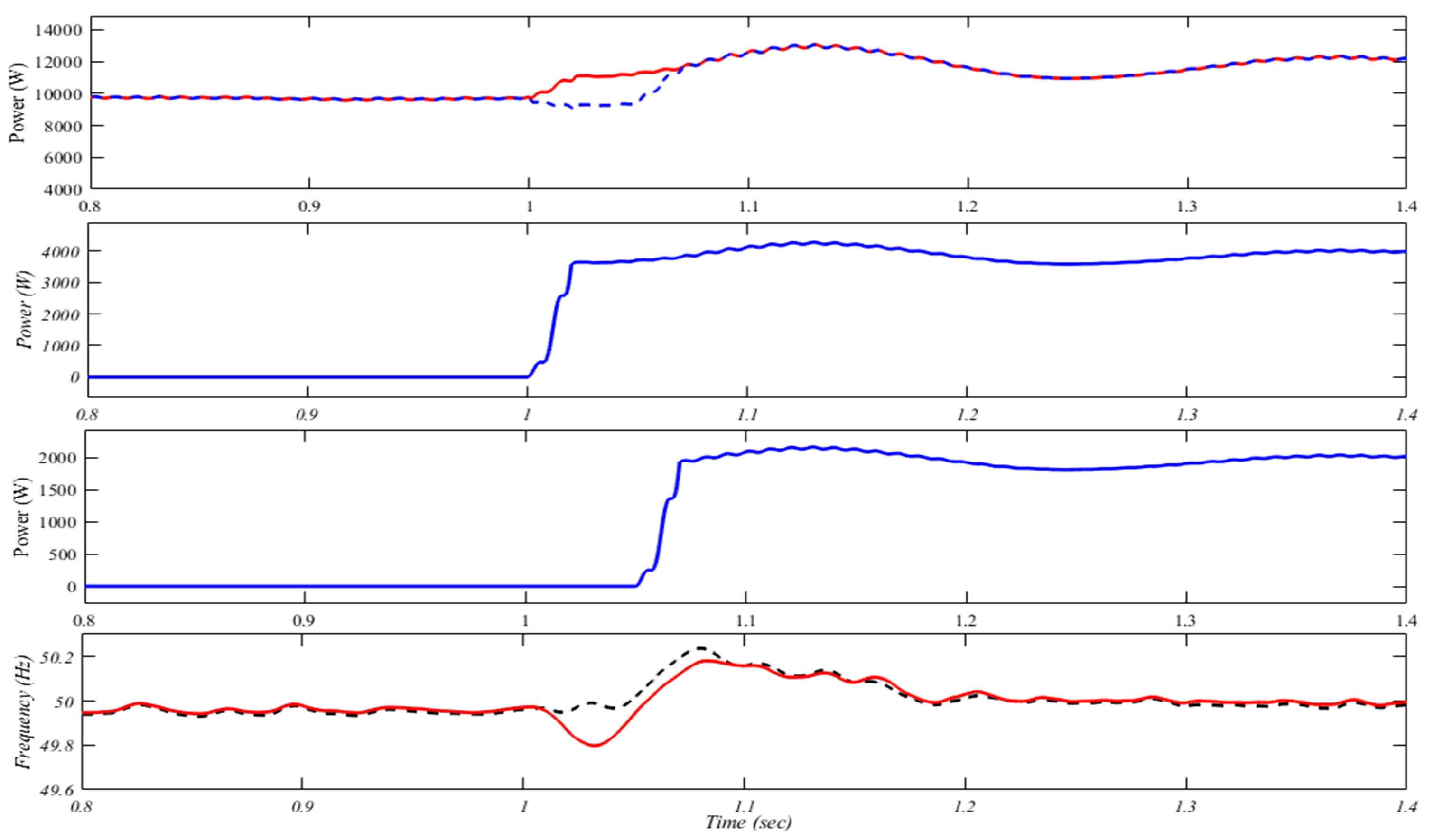
4. Simulated Results with Discussion

To prove the efficacy of the proposed system, two PV based single phase CMGs are developed and previously discussed, and five different modes of operations are considered. Each PV inverter is interfaced with the local load through an LCL filter. All of the system parameters in normal operating stable conditions are provided in Table 1. The droop co-efficient is adjusted according to the mode of operation to maintain the system frequency and stability. The active power-sharing with unity power factor is proposed in this research work. It is worth noting that reactive power-sharing and the challenges that go along with it are not included in this study. Matlab SimPowerSystem is used to develop the detailed model of the CMGs.

4.1. Normal Operation

A normal standalone operation of the CMGs before the coupling is considered in this case study. The load demand in CMG1 and CMG2 is 6 kW each. The load power and the frequency in both the MGs are shown in Figure 6. In this situation, the load demand in both CMGs suddenly increases by 4 kW at instant 0.8 s in CMG1 and at 0.9 s in CMG2. It can be observed from Figure 6 that the frequency is maintained within the allowable range as the power set point of the CMGs are modified to maintain the frequency. It is also notable that as both the systems are not connected together so CMG1 will not be affected by any change in CMG2. It can be observed that both of the systems have two different frequency profiles as they are not connected.

4.2. CMG1 Is Overloaded

In steady-state operation, if the power demand increases in CMG1 and exceeds the total power rating of the CMG1, then according to the proposed configuration, power can be drawn from the CMG2, if there is any excess power available. In this situation, the load consumption in CMG2 is always constant. In this case study, a 10-kW load is initially attached to CMG1, and a 6-kW load is connected to CMG2, so that there is excess available power in CMG2. Now the load demand is increased by 4 kW in CMG1 at the simulation time instant 1 s. It can be observed from Figure 7 that the excess power is supplied in CMG1 from the CMG2. The frequency spectrum, also shown in Figure 7, is also within the allowable range. In this case study, symmetric droop control is applied for equal power-sharing during the coupling condition.

4.3. CMG2 Is Overloaded

In this case study, the load consumption in CMG1 is constant, and load demand in CMG 2 is increased and exceeds the PV power generation rating of the CMG 2. In this situation, there are two possibilities to supply the excess load demand. One is from BESS, which is already installed in CMG 2, and the other one is if there is any excess power in CMG 1 that can be transferred to CMG2 to meet the requirement. Here, in this case study, 6 kW load is added to CMG 1 so that there is some excess power to transfer to CMG2 and initially, in CMG2 the load demand is 10 kW. Then, at the simulation time of 1 s, the total load demand in CMG2 is increased to 16 kW. In this situation, according to the flow chart, the excess power in CMG1 (4 kW) is transferred to CMG2, and the BESS within the CMG2 supplies the remaining power demand (2 kW). Thus, asymmetric power-sharing has been achieved in this case study by adequately adjusting the power set point and droop gain. It can also be observed from Figure 8 that initially, when power demand was supplied individually, both the CMGs had different frequencies and, after coupling, both the CMGs settled at a stable frequency.

4.4. CMG1 & CMG2 Both Are Overloaded

When Both CMGs are overloaded, then the excess load demand can be supplied from the BESS. But it can be noted that this BESS also has some limitations. The load demand should not be increased beyond the rating of BESS, and CMGs should not be overloaded for a long time. In this case study, initially, the load demand is 10 kW individually in both the CMGs. At simulation time instant 1 s, the load demand in both the CMGs are increased to 12 kW, which exceeds the power generation rating for both the CMGs. Figure 9 illustrates that the 4-kW excess power is supplied from the BESS, and 2 kW power is transferred from CMG2 to CMG1. In this case study an asymmetric power-sharing and a stable mode of operation is also achieved.

4.5. CMG1 & CMG2 Both Are Underloaded

When both CMGs are underloaded in this situation, the excess power can be utilized to charge the BESS. In this case study, it is considered that both the CMGs are having an 8-kW load. In this situation, according to the PM algorithm (given in Figure 4), the available excess power (2 kW) in CMG1 can be transferred to meet the load demand, and the internal excess power of CMG2 can also be utilized to recharge the BESS. It can be observed from Figure 10, that the excess 2 kW power is transferred from the CMG1 to CMG2, and 4 kW internal power of CMG2 is utilized to recharge the BESS. As both the systems are interconnected, they have the same frequency (as shown in Figure 10).

5. Experimental Results

A laboratory-scale prototype of two isolated CMGs have been developed to verify the efficacy of the proposed controller, as shown in Figure 11. Two PV simulators (100 V, 20 A) in each CMG has been used as a DC source, and further single-phase inverters are connected to supply the local load. The proposed control strategy has been developed in the LabView platform. The Mitsubishi L series intelligent power module (IPM) PM25CL1A120 is used for implementing both the inverter. The proposed control algorithm is implemented in the National Instrument-based sbRIO-9683 controller. To verify the power-sharing efficiency effectively, three different case studies have been conducted.

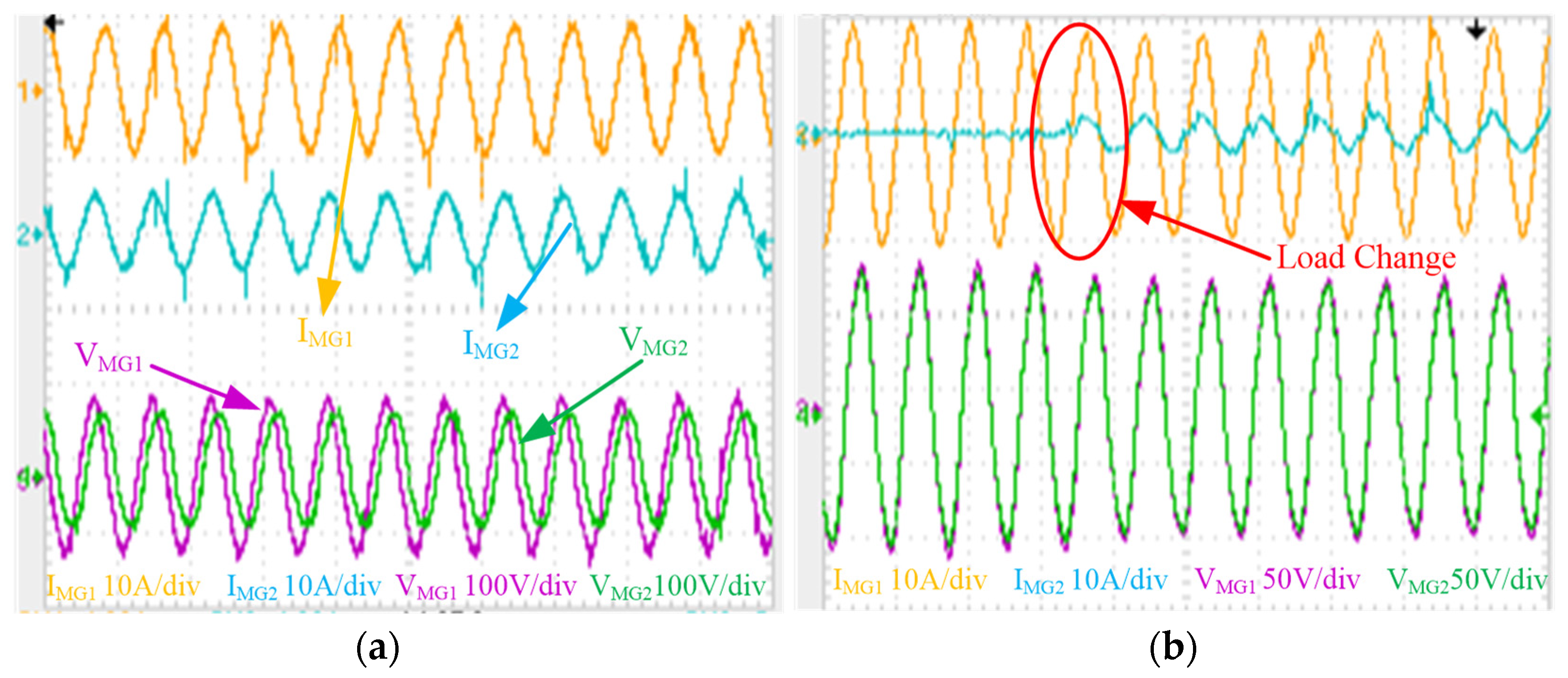
5.1. Case 1: MGs Are Operated Independently and Sudden Load Change

In this case study, both of the CMGs are operated separately and supplying the local load individually, as shown in Figure 12a. As a result, the implemented controller can maintain the desired voltage and frequency and provide the required load demand. Initially, in the case of study 1 (Figure 12a), 10 A and 5 A current drawing load was connected to CMG1 and CMG2 individually. In the second scenario of this study, as shown in Figure 12b, a transient load change condition is considered to check the efficacy of the proposed controller. In this scenario, initially, in CMG1, the load current was 10 A, and the CMG2 was in no-load condition, and after triggering the load suddenly, 5 A current was drawing by the load. It can be seen that voltage and frequency remained unchanged during this load change. This scenario provides satisfactory testing of the CMG controllers in the standalone mode of operation.

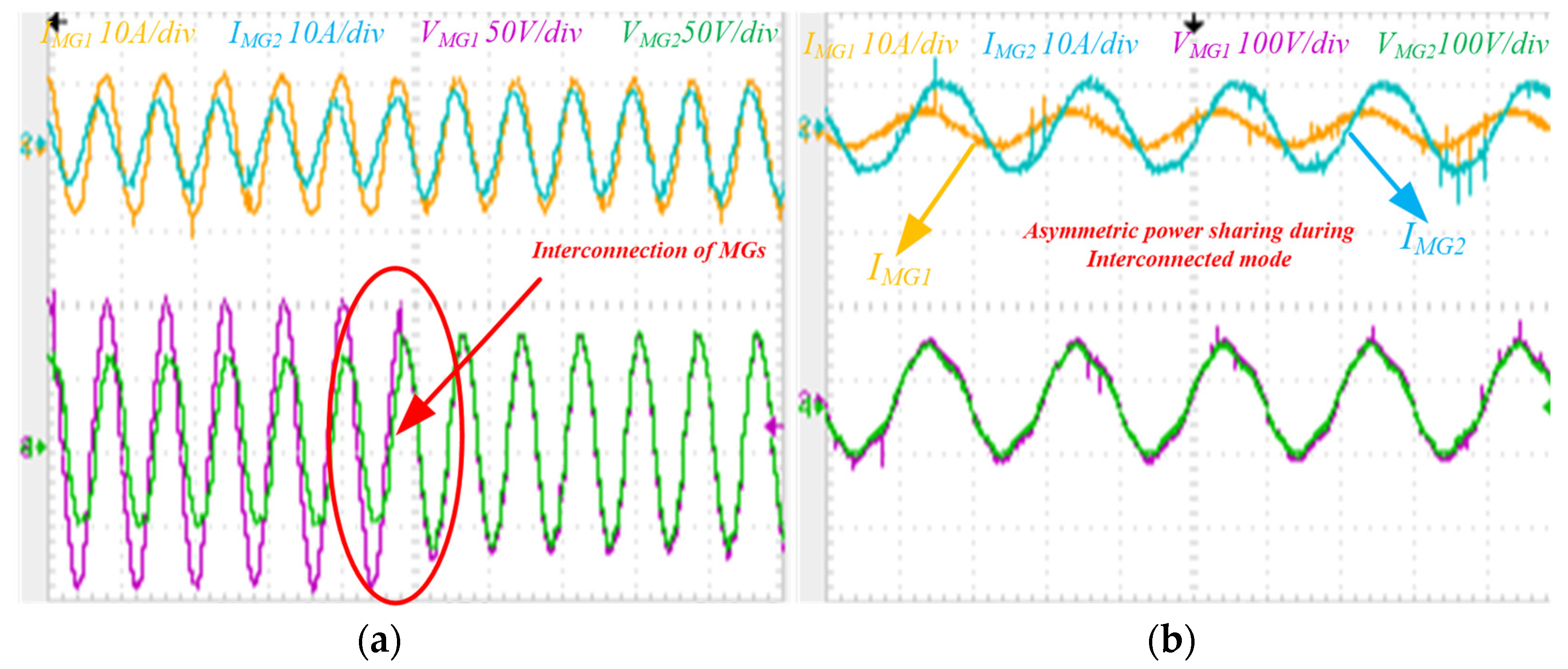
5.2. Case 2: Symmetric and Asymmetric Power-Sharing

One of the most important contributions of this research article is to share the power according to the power set point of the inverter, calculated from a PM strategy. According to the PM strategy, as shown in Figure 4, the power setpoints are defined by the power availability of the CMGs and load connected to the CMGs. In the case of coupling the neighbouring CMGs, the power should be shared symmetrically or asymmetrically as the distributed energy sources, and load demands are volatile. Low voltage CMGs have a limited capacity to fulfil the load demand. The asymmetrical power-sharing helps a particular CMG share the power according to its availability, which allows the coupled system to act more efficiently. The power-sharing performance during the coupled mode is demonstrated by representing the output current waveform of each CMG.
In this section, two different scenarios (symmetric and asymmetric power-sharing) have been considered. As shown in Figure 13a, a symmetrical/equal power-sharing has been illustrated. Initially, 10 A and 6 A current drawing load was connected in CMG1 and CMG2, respectively, and in this situation, MGs are coupled to share the total load. The PM strategy has been implemented and can be seen from Figure 13a, the loads are shared symmetrically, and the frequency is also in the allowable range. On the other hand, as shown in Figure 13b an asymmetrical power-sharing has been illustrated. In this case study, asymmetrical power-sharing has been achieved during the coupled condition, where CMG1 supplies 4 A and CMG2 supplies 8 A of load current. The system voltage and frequency are kept at their desired levels thanks to a flawless PM technique application and careful droop gain selection.

5.3. Case 3: Power Transfer between the Microgrids

In this section, finally, to check the efficacy of the coupling controller, power transfers between the CMGs have been illustrated clearly. The current flowing through the coupling switch is measured in order to show the power transfer between the CMGs. As shown in Figure 14, both the CMGs are supporting the loads individually. In Figure 14a, CMG1 is generating 18 A while MG2 is generating 14 A to support the load demand. At this instance, the CMGs are coupled, and the equal power-sharing control topology is implemented. The PCC current at the coupling time has been measured, as shown in Figure 14b. It can be clearly seen from Figure 14b that power has been transferred from CMG1 to CMG2 to share the load demand.

6. Conclusions

Sharing available energy resources among neighbouring CMGs creates a sense of isolated energy community, which can be considered a socially responsible strategy to cost-effectively combat energy poverty. The challenge related to sharing of available energy resources has been discussed in this paper, with an enhanced droop control method to strengthen the coupling efficiency of standalone neighbouring CMGs during any contingency. In addition to classic droop control, the proposed controller implements a PM-based droop control to ensure asymmetric power-sharing. Two PV based static single-phase CMGs were considered to verify the novel PM-based droop control. The MATLAB based simulation and experimental validation results conclude the following:
  • An efficient coupling scheme for available power-sharing among the neighbouring microgrid is developed. The proposed scheme is able to support neighbouring CMGs during any kind of contingency.
  • The power management-based setpoint calculation for the droop control provides an accurate power-sharing between the MGs. The proposed topology is able to share the power among the MGs in asymmetric way as-well, which does not restrict the inverters for equal power-sharing. The experimental results corroborated the benefits of this unique features.
  • The frequency of the proposed system is maintained within the acceptable allowable range (50 Hz ± 1) with the help of PM based droop control. A wide range of case studies has been considered, and the efficacy of the proposed controller for frequency regulation is verified.
It should be emphasized that the proposed technique has some limitations. If the power demand exceeds the coupled CMG rating, load shedding is the only way to keep the system stable.

Author Contributions

Conceptualization, M.B. and S.P.; Formal analysis, S.P.; Investigation, S.P. and S.M.; Supervision, M.B.; Validation, S.P. and S.M.; Writing—original draft, S.M. and S.P.; Writing—review & editing, M.B. All authors have read and agreed to the published version of the manuscript.

Funding

This research received no external funding.

Institutional Review Board Statement

Not applicable.

Informed Consent Statement

Not applicable.

Data Availability Statement

Data sharing not applicable.

Conflicts of Interest

The authors declare no conflict of interest.

Abbreviations and Notations

ECEnergy community
PMPower management
CMGCommunity microgrids
RESRenewable energy sources
BESSBattery energy storage systems
SCSupercapacitors
PVPhotovoltaics
SoCState of charge
DGDistributed generation
kɷFrequency droop co-efficient
kVVoltage droop co-efficient
ɷ*Nominal value of frequency
V*Nominal value of voltage
ω0Grid Frequency
ωisolatedStandalone/isolated Frequency
P1 & P2Generated Power from CMG1 & CMG2
P1* & P2* Power setpoints of CMG1 & CMG2
PL1Load power demand in CMG1
PL2Load power demand in CMG2
CDC link capacitor
Lf1 & Lf2LCL Filter Inductors
CfLCL Filter Capacitor

References

  1. Renewable Energy—Recast to 2030 (RED II) | EU Science Hub. Available online: https://ec.europa.eu/jrc/en/jec/renewable-energy-recast-2030-red-ii (accessed on 17 November 2020).
  2. Di Lorenzo, G.; Rotondo, S.; Araneo, R.; Petrone, G.; Martirano, L. Innovative power-sharing model for buildings and energy communities. Renew. Energy 2021, 172, 1087–1102. [Google Scholar] [CrossRef]
  3. Energy Communities | Energy. Available online: https://ec.europa.eu/energy/topics/markets-and-consumers/energy-communities_en (accessed on 22 August 2021).
  4. Fichera, A.; Marrasso, E.; Sasso, M.; Volpe, R. Energy, Environmental and Economic Performance of an Urban Community Hybrid Distributed Energy System. Energies 2020, 13, 2545. [Google Scholar] [CrossRef]
  5. Ceglia, F.; Marrasso, E.; Roselli, C.; Sasso, M. Small Renewable Energy Community: The Role of Energy and Environmental Indicators for Power Grid. Sustainability 2021, 13, 2137. [Google Scholar] [CrossRef]
  6. Erdinc, O.; Vural, B.; Uzunoglu, M. A wavelet-fuzzy logic based energy management strategy for a fuel cell/battery/ultra-capacitor hybrid vehicular power system. J. Power Sources 2009, 194, 369–380. [Google Scholar] [CrossRef]
  7. Soomro, A.; Pullen, K.R.; Amiryar, M.E. Hybrid PV System with High Speed Flywheel Energy Storage for Remote Residential Loads. Clean Technol. 2021, 3, 20. [Google Scholar] [CrossRef]
  8. Lasseter, R.H. Smart Distribution: Coupled Microgrids. Proc. IEEE 2011, 99, 1074–1082. [Google Scholar] [CrossRef]
  9. Batool, M.; Islam, S.M.; Shahnia, F. Master control unit based power exchange strategy for interconnected microgrids. In Proceedings of the 2017 Australasian Universities Power Engineering Conference (AUPEC), Melbourne, VIC, Australia, 19–22 November 2017; pp. 1–6. [Google Scholar] [CrossRef] [Green Version]
  10. Bourbour, S.; Shahnia, F. Impact of the weightings of different criteria in selecting the suitable microgrids when forming a system of coupled microgrids. In Proceedings of the 2016 IEEE Innovative Smart Grid Technologies—Asia (ISGT-Asia), Melbourne, Australia, 28 November–1 December 2016; pp. 1151–1156. [Google Scholar] [CrossRef]
  11. Shahnia, F.; Bourbour, S.; Ghosh, A. Coupling Neighboring Microgrids for Overload Management Based on Dynamic Multicriteria Decision-Making. IEEE Trans. Smart Grid 2015, 8, 969–983. [Google Scholar] [CrossRef]
  12. Jafari, M.; Malekjamshidi, Z.; Zhu, J. A magnetically coupled multi-port, multi-operation-mode micro-grid with a predictive dynamic programming-based energy management for residential applications. Int. J. Electr. Power Energy Syst. 2019, 104, 784–796. [Google Scholar] [CrossRef]
  13. Shahnia, F.; Bourbour, S. A practical and intelligent technique for coupling multiple neighboring microgrids at the synchronization stage. Sustain. Energy Grids Netw. 2017, 11, 13–25. [Google Scholar] [CrossRef]
  14. Pashajavid, E.; Shahnia, F.; Ghosh, A. Interconnection of two neighboring autonomous microgrids based on small signal analysis. In Proceedings of the 2015 9th International Conference on Power Electronics and ECCE Asia (ICPE-ECCE Asia), Seoul, Korea, 1–5 June 2015; pp. 213–220. [Google Scholar] [CrossRef]
  15. Laaksonen, H.; Saari, P.; Komulainen, R. Voltage and frequency control of inverter based weak LV network microgrid. In Proceedings of the 2005 International Conference on Future Power Systems, Amsterdam, The Netherlands, 1 January 2005; p. 6. [Google Scholar] [CrossRef]
  16. Zhou, X.; Zhou, L.; Chen, Y.; Guerrero, J.M.; Luo, A.; Wu, W.; Yang, L. A microgrid cluster structure and its autonomous coordination control strategy. Int. J. Electr. Power Energy Syst. 2018, 100, 69–80. [Google Scholar] [CrossRef]
  17. Li, F.; Qin, J.; Wan, Y.; Yang, T. Decentralized Cooperative Optimal Power Flow of Multiple Interconnected Microgrids via Negotiation. IEEE Trans. Smart Grid 2020, 11, 3827–3836. [Google Scholar] [CrossRef]
  18. Jena, S.; Kar, S.K. Defining indispensability of storage for raised renewable penetration in conventional and thermoelectric coupled microgrid: Modeling, analysis and validation. Int. J. Energy Res. 2020, 44, 5947–5967. [Google Scholar] [CrossRef]
  19. Liu, Q.; Caldognetto, T.; Buso, S. Flexible Control of Interlinking Converters for DC Microgrids Coupled to Smart AC Power Systems. IEEE Trans. Ind. Electron. 2019, 66, 3477–3485. [Google Scholar] [CrossRef]
  20. Wu, D.; Tang, F.; Dragicevic, T.; Vasquez, J.C.; Guerrero, J.M. Autonomous Active Power Control for Islanded AC Microgrids With Photovoltaic Generation and Energy Storage System. IEEE Trans. Energy Convers. 2014, 29, 882–892. [Google Scholar] [CrossRef] [Green Version]
  21. Moazami Goodarzi, H.; Kazemi, M.H. An optimal autonomous microgrid cluster based on distributed generation droop parameter optimization and renewable energy sources using an improved grey wolf optimizer. Eng. Optim. 2018, 50, 819–839. [Google Scholar] [CrossRef]
  22. Liu, B.; Wu, T.; Liu, Z.; Liu, J. A Small-AC-Signal Injection-Based Decentralized Secondary Frequency Control for Droop-Controlled Islanded Microgrids. IEEE Trans. Power Electron. 2020, 35, 11634–11651. [Google Scholar] [CrossRef]
  23. Alam, M.N.; Chakrabarti, S.; Ghosh, A. Networked Microgrids: State-of-the-Art and Future Perspectives. IEEE Trans. Ind. Informatics 2019, 15, 1238–1250. [Google Scholar] [CrossRef]
  24. Cheong, D.M.L.K.; Fernando, T.; Iu, H.C.; Reynolds, M.; Fletcher, J. Review of clustering algorithms for microgrid formation. In Proceedings of the 2017 IEEE Innovative Smart Grid Technologies—Asia (ISGT-Asia); IEEE: Manhattan, NY, USA, 2017; pp. 1–6. [Google Scholar] [CrossRef]
  25. Liu, H.; Mahmoudi, N.; Chen, K.; Liu, H.; Mahmoudi, N.; Chen, K. Microgrids Real-Time Pricing Based on Clustering Techniques. Energies 2018, 11, 1388. [Google Scholar] [CrossRef] [Green Version]
  26. Wei, B.; Marzabal, A.; Ruiz, R.; Guerrero, J.M.; Vasquez, J.C. DAVIC: A New Distributed Adaptive Virtual Impedance Control for Parallel-Connected Voltage Source Inverters in Modular UPS System. IEEE Trans. Power Electron. 2019, 34, 5953–5968. [Google Scholar] [CrossRef] [Green Version]
  27. Sahoo, S.; Mishra, S.; Jha, S.; Singh, B. A Cooperative Adaptive Droop Based Energy Management and Optimal Voltage Regulation Scheme for DC Microgrids. IEEE Trans. Ind. Electron. 2019, 67, 2894–2904. [Google Scholar] [CrossRef]
  28. Raman, G.; Peng, J.C.-H.; Zeineldin, H.H. Optimal Damping Recovery Scheme for Droop-controlled Inverter-based Microgrids. IEEE Trans. Smart Grid 2020, 11, 2805–2815. [Google Scholar] [CrossRef]
  29. Tayab, U.B.; Roslan, M.A.B.; Hwai, L.J.; Kashif, M. A review of droop control techniques for microgrid. Renew. Sustain. Energy Rev. 2017, 76, 717–727. [Google Scholar] [CrossRef]
  30. Mahmood, H.; Michaelson, D.; Jiang, J. Decentralized Power Management of a PV/Battery Hybrid Unit in a Droop-Controlled Islanded Microgrid. IEEE Trans. Power Electron. 2015, 30, 7215–7229. [Google Scholar] [CrossRef]
  31. Mahmood, H.; Jiang, J. Autonomous Coordination of Multiple PV/Battery Hybrid Units in Islanded Microgrids. IEEE Trans. Smart Grid 2017, 1. [Google Scholar] [CrossRef]
  32. Lahnaoui, A.; Stenzel, P.; Linssen, J. Techno-economic analysis of photovoltaic battery system configuration and location☆. Appl. Energy 2018, 227, 497–505. [Google Scholar] [CrossRef]
  33. Kundur, P. Power System Stability and Control; McGraw-Hill: New York, NY, USA, 1994. [Google Scholar]
  34. Glover, J.D.; Overbye, T.J. Power System Analysis and Design; Thomas, J., Sarma, M.S., Eds.; Cengage Learning: Stamford, CT, USA, 2012; ISBN 9781305632134. [Google Scholar]
Figure 1. The overall architecture of the proposed system configuration.
Energies 14 05383 g001
Figure 2. Illustration of droop control in grid connected and isolated mode.
Energies 14 05383 g002
Figure 3. CMG inverter control strategy with incorporation of PM based droop control.
Energies 14 05383 g003
Figure 4. Flow chart for power setpoint calculation with all possible power flow scenarios.
Energies 14 05383 g004
Figure 5. (a) Power flow for operation mode A. (b) Power flow for operation mode B. (c) Power flow for operation mode C. (d) Power flow for operation mode D. (e) Power flow for operation mode E.
Energies 14 05383 g005aEnergies 14 05383 g005b
Figure 6. System parameters for isolated operation of CMG 1 and CMG2.
Energies 14 05383 g006
Figure 7. Active power and frequency in interconnected condition when CMG 1 is overloaded.
Energies 14 05383 g007
Figure 8. Active power and frequency in interconnected condition when CMG 2 is overloaded.
Energies 14 05383 g008
Figure 9. Active power and frequency in interconnected condition when CMG 1 and CMG2 are both overloaded.
Energies 14 05383 g009
Figure 10. Illustration of BESS charging situation.
Energies 14 05383 g010
Figure 11. Experimental prototype of the proposed system.
Energies 14 05383 g011
Figure 12. CMGs operating condition (a) in decoupled mode and (b) the effect of sudden load change.
Energies 14 05383 g012
Figure 13. Illustration of CMGs power-sharing—(a) symmetric and (b) asymmetric power-sharing.
Energies 14 05383 g013
Figure 14. Power transfer between the CMGs. (a) Generated load current in CMG1 and CMG2 and (b) power transfer from CMG1 to CMG2.
Energies 14 05383 g014
Table 1. CMG system Parameters.
System Parameters
DC Link Capacitor (C)2000 µF
Filter Inductor (Lf1 & Lf2)6.8 mH
Filter Capacitor (Cf)30 µF
Power Rating for Inverter 110 kW
Power Rating for Inverter 210 kW
BESS Capacity10 kWh
Frequency drooping gain0.05 rad/s/W
Voltage drooping gain0.01 V/var
Publisher’s Note: MDPI stays neutral with regard to jurisdictional claims in published maps and institutional affiliations.

