Review

Distributed Generation and Renewable Energy Integration into the Grid: Prerequisites, Push Factors, Practical Options, Issues and Merits

1
Regional Centre for Energy and Environmental Sustainability (RCEES), School of Engineering, University of Energy and Natural Resources, P.O. Box 214 Sunyani, Ghana
2
Faculty of Engineering and Technology, University of Buea, P.O. Box 63 Buea, Cameroon
*
Author to whom correspondence should be addressed.
Energies 2021, 14(17), 5375; https://doi.org/10.3390/en14175375
Submission received: 10 May 2021 / Revised: 11 June 2021 / Accepted: 5 July 2021 / Published: 29 August 2021
(This article belongs to the Section B2: Clean Energy)

Abstract

:
Power system operators are in search of proven solutions to improve the penetration levels of distributed generators (DGs) in the grid while minimizing cost. This transition is driven, among others, by global climate concerns, the growing power demand, the need for greater flexibility, the ageing grid infrastructure and the need to diversify sources of energy production. Distributed renewables would not easily substitute the conventional electric grid system, perhaps because the latter is a well-established technology and it would not be prudent to abandon it, while the new distributed renewable energy technologies are generally not adequately developed to support the total load. Thus, it is becoming increasingly necessary to consider sustainable options such as integrating renewable energy sources into the existing power grid. This study is a review that is mainly hinged on distributed generation (DG) classification, the challenges of DG to grid integration, practical options used in DG integration, lessons learned from some countries with successful DG to grid integration, push factors in the growth of DGs and the merits of DG to grid integration. These standpoints of DG to grid interconnection are critical in conducting grid planning and operational studies, which should be conducted in strict observance of aspects such as optimal technology selection, optimal capacity and a suitable connection point of DGs in the network. Therefore, the perspectives highlighted regarding DG can assist power system engineers, developers of DG plants and policymakers in developing a power network that is stable, efficient and reliable.

1. Introduction

The quantity of power that is fed into the electricity network from distributed generating plants could potentially pose challenges for power system operators. These challenges range from voltage fluctuation and reverse power flow to overheating of components. The increased inflow of electrical energy into the power network necessitates significant grid reinforcement, especially in distribution networks where voltage stability is imperative. The push factors behind the increasing renewable energy (RE) penetration levels include reliability, security, advances in technology, regulatory issues and emission reduction concerns. Moreover, increasing competition in the electricity market, issues of obsolete grid equipment and capacity limitations have driven the adoption of distributed generation (DG) technologies as part of the new power systems to resolve these challenges [1]. In the current deregulated electricity sector, investors are usually skeptical in making investment decisions on power projects that involve huge amounts due to extremely long payback periods. These factors, and the deregulation/decentralization of the electricity sector, together with the growing global electricity consumption, have made DG technologies a sustainable power supply option for the near future [2].
Grid capacity expansion by means of integrating distributed renewable energy systems has become an emerging global trend, likely to have a significant impact as a result of a drop in the cost of renewable energy system accessories such as solar PV, biomass and wind energy [3]. Recently, there has been a transformative evolution in the electricity grid and industrialized countries such as Germany and Denmark are making enormous progress in increasing the share of distributed renewable energy systems in their total energy generation mix. Germany is leading the race in grid expansion and renewable energy integration, greatly favored by the implementation of feed-in tariffs in 1990 [4], which led to the installation of 92 GW capacity from solar photovoltaics, wind and biomass systems in the last quarter of 2015. Their counterparts from developing countries are still reluctant in adopting this scheme due to the technical and financial implications involved, but they have, however, expressed a desire to increase renewable energy shares in their energy production mix, as could be justified by the content of their Nationally Determined Contributions (NDCs). They have adapted their regulatory frameworks to encourage these technologies and their energy sector could experience similar progress as Germany. To efficiently integrate distributed generators into the grid, the flexible infrastructure of power electronic converters with customary tasks for power quality and conditioning are required [5]. In electricity grids dominated by distributed renewable energy systems, high grid overload may occur due to the increase in power generation from the distributed renewable energy systems not matched by increasing power demand [6]. Consequently, strategies to regulate load flow need to be focused on either monitoring consumers or the curtailment of distributed generators.
The achievement of conveniently high renewable penetration levels in the grid could be easily done through a smart grid system. This system has the ability of monitoring the power system network for overloads and intelligently rerouting the electrical energy to avoid a potential power outage. Kempener et al. [7] suggested that it is economically feasible to use smart grids over conventional systems when considering renewable injection in the grid and any grid optimization needs. The literature on this subject has identified three unique levels of renewable penetration, namely low, medium and high, which are classified in line with the kind of grid reforms required to accommodate renewable energy. Many researchers have conducted studies on renewable energy systems’ (RES) integration into the grid with emphasis on various aspects. In a study conducted by Muntathir A.T. and Chokri A.B. [8] on the optimum placement and penetration levels of photovoltaic (PV) systems on an IEEE 30-bus system using the Electrical Transient Analysis Program (ETAP), they reported a 50% penetration level and concluded that this amount was satisfactory. Zahedi [9] studied aspects relating to the push factors, merits and challenges of distributed renewable energy integration into the grid and the end user perception issues were predominant. Luhmann T. et al. [6] suggested a method of managing increased solar–wind–biomass capacity in the distribution grids in Northern Germany using low-cost solutions. They developed a medium-voltage (MV) grid model where several scenarios were simulated and assessed using a 5% load flow-dependent energy curtailment approach. They concluded that the 5% approach was a promising structure for reducing the costs of renewable energy integration into the distribution grids.
Soroudi et al. [10] argued that distribution networks have been modeled in such a way that they can only manage the flow of power in one direction. Therefore, the interconnection of distributed generators (DGs) into the grid could lead to voltage fluctuation, issues with the coordination of protective devices and reactive power control issues. The stochastic nature of solar and wind systems can hamper power reliability when they are interconnected to the grid as distributed generators (DGs). Furthermore, the capital cost of these distributed renewables is relatively high, especially for sub-Saharan Africa, such that large-scale deployment is still a challenge. Lopes and Borges [11] have categorized the challenges of interconnecting DGs into three, namely technical, economic and regulatory. Since economic and regulatory challenges are related to government policies, this review ignores these aspects and the main focus is on the technical issues. Although DGs have potential benefits, there exist complications (technical, economic and regulatory) that inhibit their easy integration into the grid and hence frustrate the effort towards the new transition in the power systems [12]. Nevertheless, increased share of DG in the energy mix will only be successful if these issues are resolved. The concerns of RE integration to the grid, such as the choice of technology and suitable connection point, should be considered when conducting grid planning and operational studies [13]. The paper presents a comprehensive review of the concept of distributed generation, issues of integrating DGs into the grid, lessons learned from countries with success stories of DG to grid integration, push factors towards the advancement of DG and the benefits of integrating distributed renewables into the power network.

Objectives and Methodology

The obtainable scientific information mainly focuses on general issues influencing the interconnection of distributed energy sources into the power grid [9,11,14]. Other authors have studied particular issues (voltage fluctuation, reverse power flow, power losses) affecting power injection into the grid using ideal test grids, with little coverage of how these issues may actually differ in a real-life grid system [8,15,16,17,18]. The authors in [19] have suggested some performance indicators to evaluate the benefits of DG units, focusing on voltage profile enhancement, lowering transmission line losses and reducing environmental impact. Similar studies using technical indicators were conducted by [20,21] with the addition of line capacity. However, there exists a gap in the literature regarding how some of these concerns have affected real-life power systems and how the situation is currently being managed by system operators. Learning from case studies and empirical experiences is important to ensure that grid management strategies are effective and practical to deploy at a large scale. As a contribution, the study constitutes a curious attempt to provide a scrutiny of the complexities of interconnecting renewables into the electricity grids and markets. It offers informed viewpoints on the issues and solutions resulting from proven best practices used by power system operators and electricity markets across a few successful countries across the globe. The study emphasizes the practical application of methods in the real-world setting with theoretical foundations and empowers the improvement of supportive policies. It deliberates on renewable energy integration issues, hence making sure that grid operators with insignificant renewable penetration levels can learn from the successes accomplished by their peers.
The study will start with the explanation of the concept of distributed generation, which is widely disputed among countries and professional institutions. This is followed by issues common to the interconnection of distributed energy resources into the main grid and some selected case studies. A summary of the benefits of DG units and some successful grid integration approaches currently adopted in some countries is presented. The paper ends with a discussion and future perspectives. Figure 1 shows a summary of the methodology adopted in this paper.

2. The Concept of Distributed Generation (DG)

There is no universally accepted definition of DG and the available literature on this subject is not consistent [22,23]. According to the Department of Energy in the United States (US), DG is defined as the utilization of small, integrated or standalone energy (electricity or thermal energy) production units whose installation is near load centers. Solar thermal, photovoltaic, wind turbines, micro-hydro turbines, fuel cells, generating sets, combustion turbines and biomass systems are all distributed generators. These DGs could either be standalone or grid-connected [24]. The Institute of Electrical and Electronics Engineering (IEEE) defined DGs as power generation facilities that are considerably smaller in capacity than centralized power plants, usually 10 MW or less, in order to facilitate their interconnection at almost any point within the power grid.
According to [25], DGs could also be defined as a small source of power production for storage (usually within the range of less than a kW and tens of MW), which is not a portion of the huge, centralized power network and is located close to the load. Another school of thought defines DGs [26] as power pockets usually located near consumers, which have a relatively small capacity of 30 MW or less, with the ability to economically support the distribution grid. This description involves DG technologies such as photovoltaic systems, concentrating solar power, micro turbines, reciprocating engines and fuel cells. Furthermore, terminologies such as decentralized generation, distributed energy resources (DER), dispersed generation and embedded generation have also been used interchangeably with distributed generation [27]. In addition, DG is defined by some countries in line with the voltage level where the DG is connected, while other countries consider DGs as power sources that feed consumer loads directly. Table 1 shows how some countries and institutions define DGs [22,24].
However, the definition of DG adopted in this study based on the literature is dispersed, small- or medium-sized, integrated, electricity-producing machineries that are not centrally managed by the main grid and are mostly connected close to load centers in order to improve the power supply. Their power management strategy is usually independent of the central grid and they are mostly connected towards sites where power is needed. The central focus of this definition is the dispatch of electricity, which is opposed to the centralized control of power flow with the high possibility of an extensive power outage.

2.1. Considerations of the Classification of DGs

As seen in the review on DGs, there are several schools of thought regarding the definition of a DG as one moves across countries and professional bodies, and it is challenging to establish distinctive benchmarks for DG capacity ratings. Below are some commonly found criteria used in the classification of DG. Different scholars have diverse views on the connection point of a DG plant. Most scholars argue that the suitable location of a DG plant should be at the low-voltage (LV) network where consumers will easily utilize the energy at minimum system losses [13]. However, some insist that a high-voltage (HV) network could equally host a DG plant [24].
The maximum capacity of a DG that can be conveniently hosted by the conventional grid is also a widely disputed aspect among countries and professional institutions around the world. The DG capacity is also a critical factor when making a connection to the main grid since every connection point has a maximum amount of power that it can accommodate above which the system could become unstable. In essence, DG should be able to provide active power in the network to which it is connected and could sometimes feed reactive power and/or other ancillary services [24]. Usually, the term “distributed generation” is associated with some form of power technology, e.g., renewable energy or non-renewable technology.
Ownership of a power system facility is used by some scholars as a criterion to determine whether or not it should be considered a DG. Others have argued that the ownership of a DG unit should be an Independent Power Producer (IPP) or a power off-taker. However, Ackermann et al. [24] rejected the aspect of ownership as an important component of a DG’s definition, stating that consumers, Independent Power Producers (IPPs) and governments can own DG plants. Figure 2 shows the classification of DG technologies.

2.2. Push Factors in the Increasing Addition of DG in the Power System

The proliferation of DG and its present role in grid integration can be grouped into three main classes, namely environmental, economic and regulatory [22,29]. These push factors are briefly discussed below.

2.2.1. Environmentally Motivated Factors

The need to decarbonize the power grid and reduce greenhouse gas (GHG) emissions is among the main push factors for distributed renewable energy resources (DRES). Since DG deployment would not need any installation of new power lines or large power plants, this reduces the environmental issues that come with the construction of these facilities and the mounting public opposition. Institutions that are concerned with the protection of the environment have raised concerns regarding the deployment of onshore wind farms, citing noise and aesthetic inconvenience [12]. Therefore, a compromise needs to be made between sustainable energy supply options and the necessity of preserving the scenic beauty of the atmosphere. Others argue that renewable energy technologies such as wind, with almost no GHG emissions or waste management issues, should be encouraged. However, these environmental factors must be backed by regulations, obliging actors in the power sector to meet environmental sustainability guidelines. Moreover, economic incentives for environmentally friendly sources of power could also motivate investors to consider investing in clean energy systems.

2.2.2. Economic Factors

Because distributed generators are relatively small in capacity, they involve less capital investment and risk. This could, therefore, encourage investors to become involved in the business of power generation through DG. The operation and maintenance (O&M) cost of DG is lower, partly because they are mostly located around load centers where there are minimum losses.
In addition, the liberalization of the electricity market acts as a push factor for DG deployment in that a free market with limited restrictions would attract investors. Investors in the power industry would, therefore, rush into the power market to exploit the benefits [29]. Furthermore, a drop in the cost of renewable energy system components such as solar is also a push to growing DG deployment.

2.2.3. National/Regulatory Factors

Most countries are increasingly adopting policies that target the deployment of DGs, especially renewables. This is because modern societies greatly depend on electricity, such that any interruption in its supply could cause devastating political, economic and social consequences. Hence, DGs, especially renewables, are a favorable means of sustainable energy supply and security. Moreover, advocates of electricity market reforms argue that a completely competitive electricity market will lead to low electricity tariffs and improved services rendered. This market structure will encourage the installation of many distributed generators by investors in the power sector [22]. Furthermore, the increase in the electricity demand of countries is an important push factor in the deployment of DGs since more generators will be required to meet the growing demand.

2.3. Grid Expansion through Distributed Renewables

In the pursuit of sustainable development, countries have adopted renewable sources for electricity generation to achieve goals such as decarbonizing the production of electricity and increasing energy access [30]. Advances in technology and a drop in the cost of renewables have encouraged the progress of renewable penetration in the electricity mix in some countries.
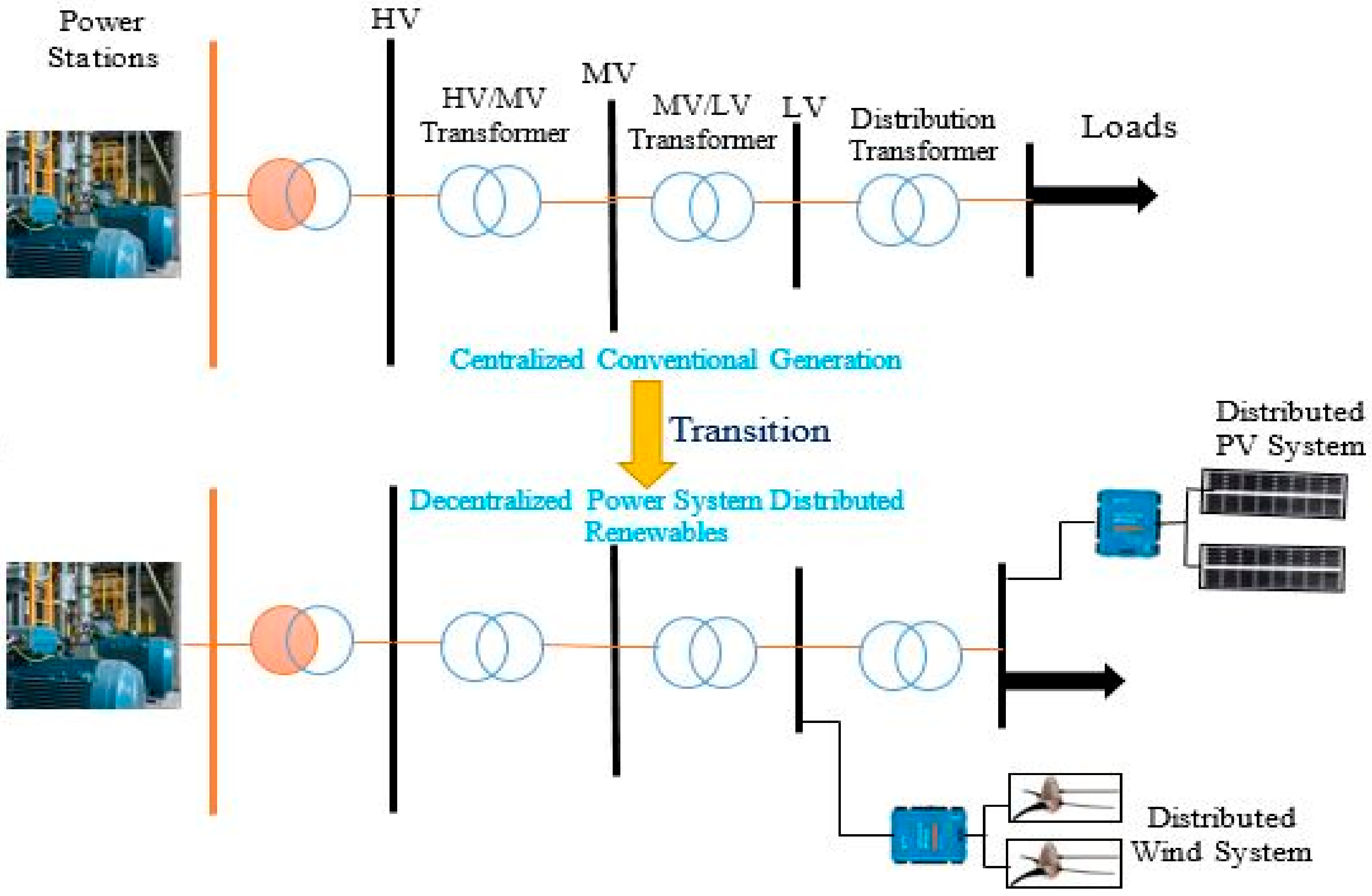
RES to grid integration permits acceptable amounts of renewable power (solar, wind, biomass, hydro etc.) to penetrate a pre-existing power network. This involves cautious attention in the areas of the type of renewable resource, components of the RES, installation and operation. The renewable energy penetration levels must be connected efficiently to the grid such that the interconnection accounts for the effects on the power network at various points. Figure 3 shows the concept of distributed renewables and their interconnection in the grid.
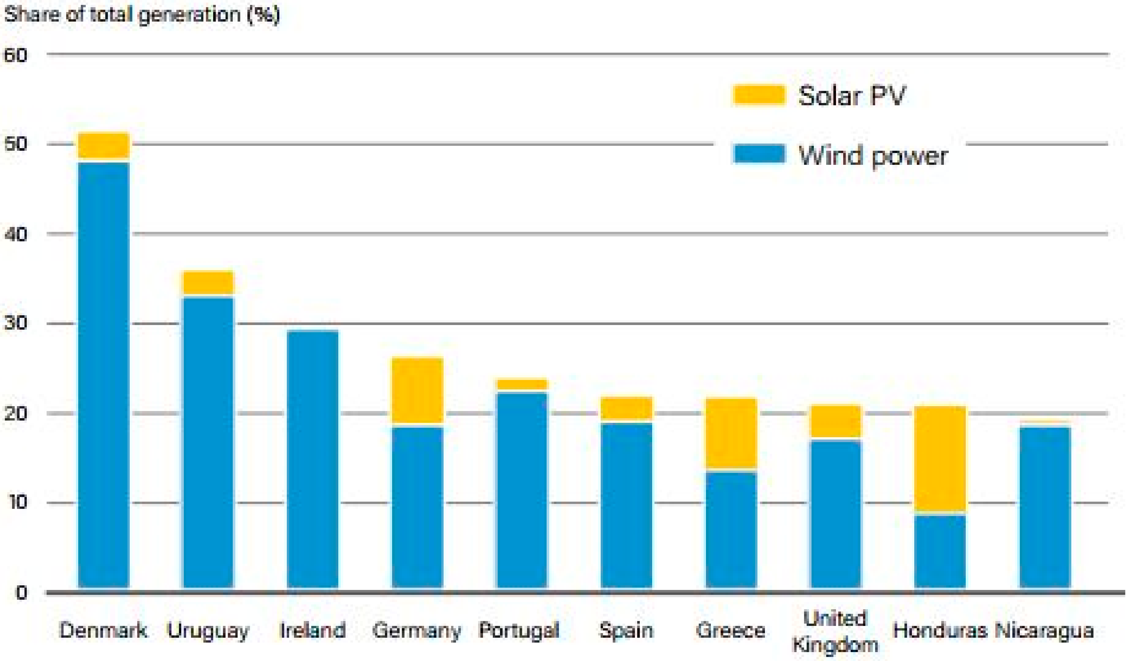
At the sub-national level, a growing number of governments in many regions have become leaders, setting more ambitious targets than their national counterparts. There has been a continuous increase in renewable energy deployment in developing countries, and distributed renewables have been mostly used to power off-grid communities. In 2019, policies to improve variable renewable energy (VRE) integration into the grid were focused on market structure, demand-side management (DSM), improvement in transmission and distribution networks. According to the REN21 2020 Global Status Report [31], the worldwide policy drive for renewable energy integration with its associated technologies, such as storage systems, continues to place emphasis on the need to improve the flexibility of the grid, control and grid resilience. This further supports the rationale of this study, as a current challenge that needs further research. Figure 4 shows the annual percentage share of solar–wind electricity generation in the top 10 countries.
Distributed renewable energy systems, which are usually scattered, small-scale generating plants, make up approximately 1% of the electricity generation mix worldwide, but their endorsement is accelerating [31]. The growth in the adoption of distributed renewable systems offers new benefits and challenges. For residential and commercial consumers, benefits include the possibility to generate their own electricity through renewables, minimizing the overreliance on the grid. Figure 5 shows the evolution of the net annual increase in renewable and non-renewable sources in the electricity mix.
Nations embracing an integrated planning scheme, an electrification method that comprises grid extension, solar home systems and mini-grids, have experienced a rapid growth in electricity access [31]. Countries such as Tanzania, Nepal, Cambodia, Rwanda, Kenya, Myanmar, Bangladesh and India have seen the most dramatic rise in electrification recently.
The DG to grid integration must take into consideration the selection of an optimal connection point, suitable capacity and the type of DG technology. However, improper optimal planning can negatively influence the performance of the distribution network. Therefore, it is imperative to properly plan DG interconnection to the grid [9,32].
The connection of DGs to the grid presents significant effects on system stability, power quality and voltage profiles; consequently, these DGs could be regarded as geographically localized voltage control points [33,34,35]. The number and capacity of connected DGs to the network will determine the amount of impact on the power quality; huge and uncontrolled injection of power from these systems could have a negative effect on the power quality [34,36]. Power quality is a critical factor in the power network, especially now that there has been an upsurge in new electrical equipment on the market that is very sensitive to any change in voltage. Power quality involves the measurement of aspects such as the amount of voltage variation (over/under voltage), frequency variation and harmonics [9].
In countries with advanced energy markets, such as Germany, a connection request from an energy project developer is followed by a detailed grid compatibility check [37] by the utility operator in order to ascertain which node or bus on the grid could be the most cost-effective point to inject power. The analysis considers both the grid expansion cost and cost of generating and transporting the electrical energy to the grid connection point.
The grid impact assessment essentially makes sure that the voltage and current limits of power system components are respected, since these are critical parameters in determining the energy-hosting capacity of the grid. The current limits of equipment, often referred to as ampacity, must not be exceeded so as to avert equipment damage. The grid assessment or compatibility check takes into consideration two critical scenarios [37]: the highest possible power produced with the smallest possible energy demand, and the minimum possible power produced with the maximum possible power demand.
The choice of an appropriate connection point of the DG plant to the grid is a central task in the integration process. The injection of renewable energy systems (RES) near load centers or distribution transformers will cause fluctuations in power flow, which have an influence on the entire voltage of the network [9]. Power fluctuations in a low-voltage (LV) network cause unwanted voltage variation, and the situation becomes even worse at high renewable penetration levels, where there will be a sharp rise in the voltage level, mostly under conditions of reduced energy consumption. Therefore, the LV network should be equipped with automatic voltage regulators in order to control the voltage level at that section of the grid.
Voltage stability is another important precondition, and various countries, regional blocks (e.g., European Union) and professional organizations, such as the Institute of Electrical and Electronic Engineers (IEEE), have set standards for power system operation. The European norm for voltage limits has a tolerance of ±10% in daily power system operation [38], while the IEEE standards recommend a tolerance of ±5%. The operation of power system components should be managed with respect to these voltage limits. Energy utility companies usually use a transformer tap changing functionality and capacitor bank switching to regulate the voltage in the constantly changing load situation. These actions help to maintain a stable voltage in the network. Figure 6 shows a profile of voltage ranges as we move across the grid.

2.4. Location and Capacity of DG on a Power Network

The integration of DGs into the distribution network can be beneficial to utility companies, power system operators and power consumers. However, if critical aspects such as the connection point and capacity of the DG are not appropriately determined, it could cause the degradation of the performance of the network. This situation could also lead to an increase in power losses and voltage fluctuation. Consequently, DG coupling to the grid, especially the distribution network, would involve the optimal planning of components, determination of optimum hosting capacity and selection of an optimum connection point. Selecting an optimum DG connection point improves the system’s reliability and security while increasing the penetration level and reducing the generation costs. Moreover, when the capacity of a DG unit is properly sized, it reduces the capital cost of purchasing equipment in a supposedly oversized system and hence enhances the efficiency of the network [40].

3. Some Practical Options Used in DG to Grid Integration

3.1. Vigorous Voltage Regulation at the Level of Substations

At the level of the substation, HV/MV transformers adapted with voltage regulation functionality are used to adjust the voltages in the transition between the HV/MV networks [37]. Most utilities in the past used voltage regulators mainly as an intervention mechanism to compensate for voltage fluctuations on the HV network and stabilize the MV to a fairly constant level. With the advent of renewable energy integration in the grid, power system operators in Germany [37] have incorporated power electronics and software applications in order to adjust MV levels with respect to the percentage of renewable energy penetration and the load flow situation at the substation. This is done to subdue the increasing voltage on the MV network in situations of renewable injection. However, this approach has a number of challenges. For instance, voltage variation could negatively affect commercial manufacturing plants connected to the power network at the medium-voltage (MV) level, which limits the widespread application of the dynamic voltage control. Moreover, the possibility of reducing the voltage in a network will depend on the physical spread of the renewable energy systems in a given MV grid area, such that energy systems that are far from the substation could present problems when reducing the voltage. Nonetheless, the application of this method is viewed by the German Distributed System operators as one of the most cost-effective procedures to increase the hosting capacity of the grid [37].

3.2. Modified Grid Configuration

Grid expansion by means of adding distributed generators requires optimizing the structure of the existing grid in a way that reduces power losses, aids fault detection/correction and creates physically accessible switching stations [37]. With the rising renewable penetration associated with the necessity for grid expansion, a techno-economic problem arises, which provokes system operators to set supplementary goals: avoid as much as possible the creation of new transmission lines or power substations. This additional goal of reducing the expansion of the power network conflicts with the previously stated optimization scheme.
Actions geared towards the reduction of grid impedance would improve on the hosting capacity of renewables in the power network. A practical approach often used by German system operators to reduce grid impedance is the closed-loop application in MV networks [37], where a radial MV grid configuration is transformed into closed rings where each substation is connected to more than one energy supply line. This approach connects previously autonomous transmission lines that were fed by a common distribution transformer to a switching station, thereby creating a closed loop. However, this method makes the detection of faults and fault recovery very difficult and the approach remains controversial among power system operators. Therefore, sustainable methods that evenly distribute injected renewable power into the entire grid need to be developed for optimum utilization of the existing grid capacity.

3.3. The Use of the ‘N Minus Zero’ Regulation

Another technique used by system operators to increase the penetration level of renewables is by establishing renewable energy generators to serve as a backup, such that, when there is a fault in one part of the grid, the backup supplies the grid. Renewable energy systems can be continuously added to the grid as required by the energy demand and grid stability, but they could become detached if the stability of the network is compromised. A power substation could be equipped with an additional HV/MV transformer that helps to support the network during either system maintenance or other contingency events. This transformer could be used to host more renewable energy systems in the given MV network. While this method would improve the utilization of the available grid capacity, it, however, renders power system operation more complex [37]. Simpler methods must be developed with clear implementation guidelines and protection measures so that renewable energy systems can be conveniently added to the grid in an incremental manner.

3.4. Reactive Power Control

Since the injection of active power in the grid causes a voltage rise, the ability of distributed renewable energy systems to generate reactive power is used by system operators to control the voltage quality. The injection of reactive power neutralizes the voltage rise, thus improving the ability of the network to host the renewable energy system [37]. Advanced methods such as automatic supervisory control systems to regulate reactive power injection have been used by system operators at the HV level. The control of reactive power can also be used to smooth the reactive power imbalance in the MV network, which is usually supplied by generators.

3.5. Creation of Express Feeders in the MV Network

Some system operators have opted for the creation of express feeders that connect HV/MV substations to distributed generators for the evacuation of energy at a higher current carrying capacity. The express feeders consist of transmission lines with huge cross-sections (500–800 mm2) with the ability to transport large amounts of electricity to the consumers. The voltage drop on these lines is low due to the large cross-section, and, consequently, the reduced voltage drop can significantly increase the hosting capacity of the MV network [41]. This approach has proven to be economical in areas where voltage complications due to high renewable penetration are observed.

4. Issues Resulting from DG to Grid Integration

Power networks comprising distributed generators around load centers with varying power demands present challenges in terms of the operation and control of the entire system [42]. These issues range from under-voltage, harmonics and over-voltage to transient stability [8].
In the past, the processes of electricity generation, transmission and distribution were run as autonomous processes. With the increase in the integration of distributed generators (DGs) in the grid, the traditional method of managing power systems has slowly been changing. The modern power grid has DGs as important components. The integration of DGs into the grid could have positive and negative effects on the transmission and distribution network. The impacts of DGs on the distribution network are presumably more, due to the fact that they are mostly connected at the distribution network. These impacts have to be carefully examined so that optimum grid performance can be achieved. As distributed energy resources become prevalent on the power grid, the nature of the network and its operation changes in order to handle the power flow in both directions [17]. Some of the issues are discussed below.

4.1. Voltage Level Fluctuations

Sustaining a relatively stable voltage level in a power network is vital for the proper functioning of the components of the grid. Currently, most DGs are located near load centers, where they supply electricity to consumers, and any substantial change in power flow will have effects on the feeder voltage since the power flow and voltage are greatly influenced by the changing demand and generation. The flow of electric current to loads in an electricity distribution network whose configuration is radial is prone to a positive voltage drop as one moves down the network, and this could cause fluctuations in voltage amplitude at network nodes [5]. The addition of a distributed renewable energy system in the electricity network affects power quality in the same manner as disturbing loads as they may also emit such disturbances as long-term and short-term voltage variations, voltage flickers and harmonic distortions. In a power system network with distributed generators, voltage increases and voltage drops can be observed depending on the scenario in question. The non-dispatchable nature of solar energy systems (i.e., the production of electricity that cannot be regulated to match the fluctuating power demand) is a potential source of voltage fluctuations in the grid. The power network must be designed such that any change in the system voltage is restored by some voltage regulatory circuitry [18].
When a distributed generator injects power into the grid, there is an effect on the voltage regulation since it greatly depends on the power flow in the network. There will be no violation of the voltage limits if the DG plant is located near the loads in a distribution feeder and the DG’s power factor is in unison with that of the load [28]. Here, the main grid supplies less energy with a reduced feeder current and, therefore, the voltage drop is reduced. Conversely, as the electricity generated by the DG plant goes beyond the feeder load, or at an extreme power factor, there will be an increase in voltage. This increase in voltage is caused by a reverse power flow and it depends on the DG capacity, power factor and grid impedance. The increase in voltage at a connection point of a DG is a result of the power supplied to the network, and for radial feeders, this change in voltage can be calculated by the following equation [43]:
Δ V = P S P L R + Q S Q L X V
where PS and QS are the DG’s real and reactive power, and PL and QL are the real and reactive power of the line load. R and X are the resistance and reactance of the line linking the DG to the substation. V is the line voltage at the point where the DG is connected. This scenario is illustrated in Figure 7 below.
The changes in voltage could possibly lead to a situation of voltage violation, where the system encounters voltages outside of the standard range specified by the regulatory authorities. These voltage fluctuations can further lead to wear and tear in customer electrical appliances and grid equipment [44,45].

4.2. Effects on Power Line Losses

The flow of electrical energy in a conductor will incur some power losses, which can be evaluated with Ohm’s law. In essence, the losses incurred by a current-carrying power line can be analyzed with the following Equation:
P l o s s = 1 T 0 T i t 2 R   d t
For a sinusoidal current,   i t = I m a x s i n ω t , the average power loss, PLoss, over a complete cycle (T = 2π) is calculated as:
P l o s s = 1 2 π 0 2 π I m a x 2 S i n 2 ω t × R   d ω t
which, on simplification, gives
P l o s s = I 2 R
where:
PLoss = average power loss in the line;
I = root mean square (rms) current of the line;
R = resistance of the line.
As seen in the power loss equation, current is a function of the power flow in the lines and any changes in power flow affect the losses in the line. The amount of loss incurred in a power system as a result of DG integration will depend on the quantity of electrical energy injected and the connection point of the DG to the grid. When DGs are connected to loads in a distribution feeder, the energy supplied by the DG will be directly utilized by the electrical appliances and this reduces the flow of power as well as losses in the feeder. Moreover, the flow of power from the main grid (HV/MV network) to the load is reduced and the risk of grid overloading is minimized (advantage of DG integration) [28]. In a situation where the energy supplied by DGs into the distribution network is more than the conductors were initially designed to accommodate, there will be increase in power losses in the network. The cumulative effect of power losses can significantly affect the cost of managing the network, and, most often, this cost is shifted to consumers through increased tariffs.

4.3. Variability of Wind and Solar Resources

The quantity of electric power generated by a solar/wind energy system relies on the availability of sun and wind resources at the particular location. This is because solar radiation and wind speed are constantly varying, which equally makes the output of these energy systems constantly changing. Since power generation from these sources varies with time and location, fluctuations in power output could lead to grid instability and low reliability [46].
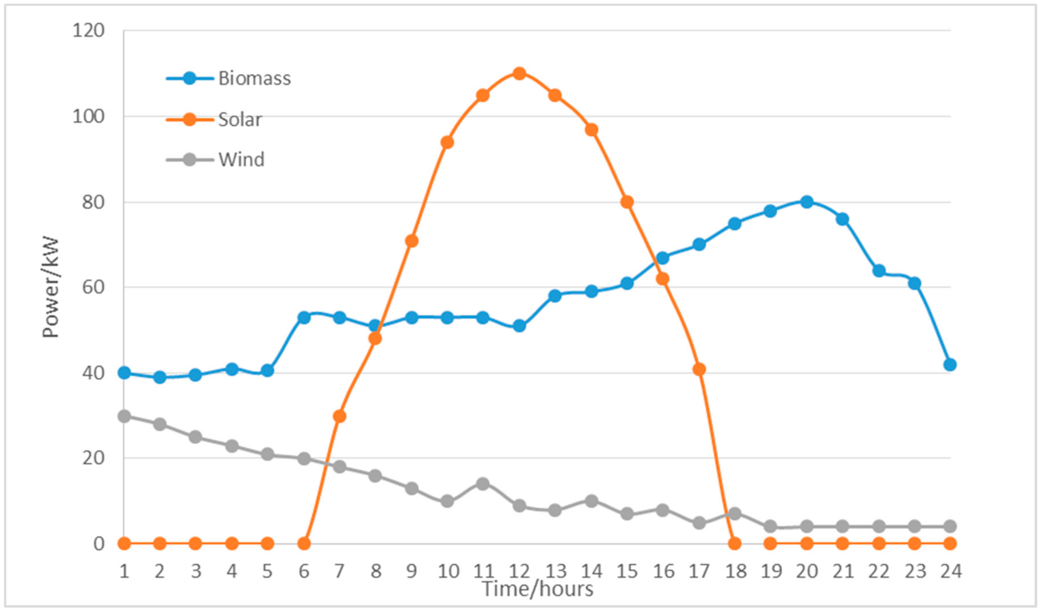
Furthermore, these intermittent energy systems have a fairly weak correlation with the energy demand and would negatively affect grid losses. For example, if the energy demand at night is low and the wind turbine output is high due to high wind speed, more energy will be exported to the main grid and this will increase losses. This situation could be resolved by adding a local storage system to locally stabilize the flow of power and avoid the export of power [47]. Figure 8 below shows the variation in renewable energy resources in a particular location.

4.4. Issues from an Economic Perspective

Distributed generation could be challenging when viewed from the perspective of managing conflicts between the utility and power consumers. The standard business model used by most utilities, especially in Africa, is selling electrical energy and being the sole actor in the management of grid infrastructure. In the event that a utility customer installs rooftop PV, this will mean that the customer will offset part of their electricity and probably sell some to the grid operator. Apparently, there are growing concerns about the economic sustainability of utility revenues in the context of rising distributed renewables from customers. Uncontrolled injection of power from distributed generators into the main grid could cause thermal stress on grid components, leading to a reduction in the lifespan of the equipment. The injection of power from DG units above a certain penetration level causes transformers [49,50,51] and conductors [52] to wear out before their manufacturer set time. When equipment wears out earlier than the time stated by the manufacturers, this increases the operation cost for system operators and electricity tariffs could be affected.

4.5. Transient Voltage Changes

The connection of certain types of DG units to the distribution grid may lead to the occurrence of voltage changes due to switching operations in the DG installation, usually at start/stop phase of the equipment or a switch in a capacitor bank. Internationally, at the moment, there is no particular designation of the transient voltage change and there are also no limit values for this disturbance [5]. The DG plant can introduce transient voltage changes into the system if relatively large current variations are permitted during the process of DG connection and disconnection from the grid. The magnitude of the current transients can, to a greater extent, be controlled during the design stage of the DG. The interconnection of synchronous generator-based DGs in the grid causes an insignificant disturbance when the synchronization is properly done, and anti-parallel soft-start components are used to reduce the magnetizing current of induction generators to a value that is less than its rated current. On the other hand, disconnecting a generator that operates at full capacity could cause substantial voltage drops.

4.6. Voltage Flickers

The integration of some distributed renewable energy sources such as wind energy systems will introduce voltage flickers into the power network. This is because their output voltage varies with the changing wind velocity and direction. According to the British Standards Institution, voltage flicker assessment should be conducted at the system design stage [53] for wind energy systems to be connected to HV or medium-voltage (MV) networks. Flicker indices P s t   and P s t should be evaluated using the following formula:
P s t = P s t = C φ k , v a S n S k
where:
  • C φ k , v a is the wind farm flicker coefficient obtained through a series of wind turbine tests;
  • φ k is the network impedance phase angle;
  • v a   is the annual average wind speed;
  • S n   is the wind farm rated power;
  • S k is the short-circuit power at the point of common coupling (PCC)

4.7. Harmonics Distortion

Distributed renewable systems such as wind turbines, which have power electronic components such as inverters, at some point in the energy conversion process, may introduce current harmonics accompanied by voltage distortion [5]. The order and magnitude of the current harmonics will greatly depend on the type of converter, inverter characteristics and the mode of operation. Nonetheless, most recent inverters connecting DGs to the power network have the ability to actively shape their current output to an acceptable limit, although some of the injected harmonic currents can distort the voltage profile, which can spread throughout the entire grid [54,55]. For wind turbines that have induction generators incorporated, there may be the occurrence of harmonics within a short time interval at startup, caused by a power electronic device. Some loads could also be a source of harmonics, where they introduce unwanted frequencies into the power grid in multiples of 50 or 60 Hz, and this could cause the power system to malfunction [18]. In summary, the presence of harmonics in a grid gives rise to diverse issues including temperature rise in the equipment, a drop in the power factor of power system components, a reduction in the performance of electrical devices, faulty responses of protective devices, communication signal interference, failure of neighboring equipment through resonance, noise, undesired vibration of electrical motors, etc. [16].

4.8. Grid Instability

In the past, power networks were radial, with a unidirectional flow of power, and grid operators interconnected DGs in a ‘fit and forget’ style. However, greater power penetration from the DG became problematic as the injected power reached unacceptable levels. When connected to the grid, the DG displaces a substantial quantity of power from the main grid, which affects the dynamics of power system operation. The idea of a change in the dynamics of grid operation is also supported by [29], where the authors argue that the grid will be exposed to system instability, especially for a DG power penetration level of over 30%, in a situation where the DG unit replaces a major conventional generator in the main grid, causing a drop in the existing inertia in the grid. However, the penetration level greatly depends on the limits of the grid.
When a grid system has adequate rotating inertia, this aids in stabilizing the usually large imbalance that occurs during operation between power demand and supply [28]. On the other hand, when a DG unit replaces a central generator in the main grid, this causes the existing inertia to drop and can increase the degree of imbalance between power demand and supply. In the event of a drop in the rotating inertia and withdrawal of a large-capacity DG, the stability of the grid becomes fragile.
Consequently, instabilities in the grid caused by DG integration can be resolved using the ‘fault ride-through’ criteria, where standard time durations are defined for DGs to remain connected to the grid during voltage rises or falls (faults). This standard duration is usually set for large generators in the main grid, and it is becoming imperative to set the same standards for DGs coupled to the grid at the level of distribution. The criteria can also assist in frequency and voltage stabilization during faults; however, this depends on the capacity of the DG unit. As DGs are continuously coupled to the grid during local faults, there could be interference in the operation of the local protective devices such that fault recovery and identification becomes difficult [28]. Therefore, the growing DG interconnection into the grid requires synchronization among local protective devices and fault ride-through criteria, and in-depth research needs to be conducted in order to ensure a stable grid with DGs.

4.9. Increase in the Fault Level and Fragile Protection System

DG interconnection into the distribution grid can influence the fragility of the network since the DG could possibly contribute to the fault current. The manner in which the DG plant is interfaced with the grid greatly influences the amount of fault current contribution and this could mean that the ratings of the equipment are violated. For example, DGs that are connected to the grid via an inverter rarely add to the fault current compared to those with a direct connection to the grid, where significant quantities of fault current are added [56]. When DGs add significant quantities of fault current into the grid, this negatively affects the protective devices in the network causing improper functioning of protective system and difficulties in detecting faults. Therefore, DG to grid interconnection will need a protection management system equipped with the ability to support a bidirectional flow of power [57].
Thermal overload poses a problem to the distribution network via heating as a result of power in the network exceeding the power ratings of the system components [58]. Transformers are one of the most expensive components of the power system and any overloading would cause several collapse mechanisms and sometimes lead to complete damage.
The maximum current-carrying capacity of an overhead transmission line depends on the total heat transfer to the cable and the resistance, as shown in Equation (6) [59];
I L = Δ H R
where IL is the overhead transmission line current (A), R is the line resistance and ΔH is the heat transferred from the cable to the environment. When components are overloaded, there is a need for an upgrade of the equipment to a higher rating. Hence, when huge amounts of renewable energy are injected into the grid, the power system will need to be able to support this injected energy.

5. Review on Case Studies

We performed a literature review to elucidate the three main aspects of this study: (1) DG as a potential solution to some challenges in the power grid; (2) the impacts of high penetration renewable energy systems on an existing electric grid; (3) the general approach used by other researchers to integrate DGs into the electric grid. This section discusses aspects relating to each of the items mentioned above.

5.1. Case of South of England

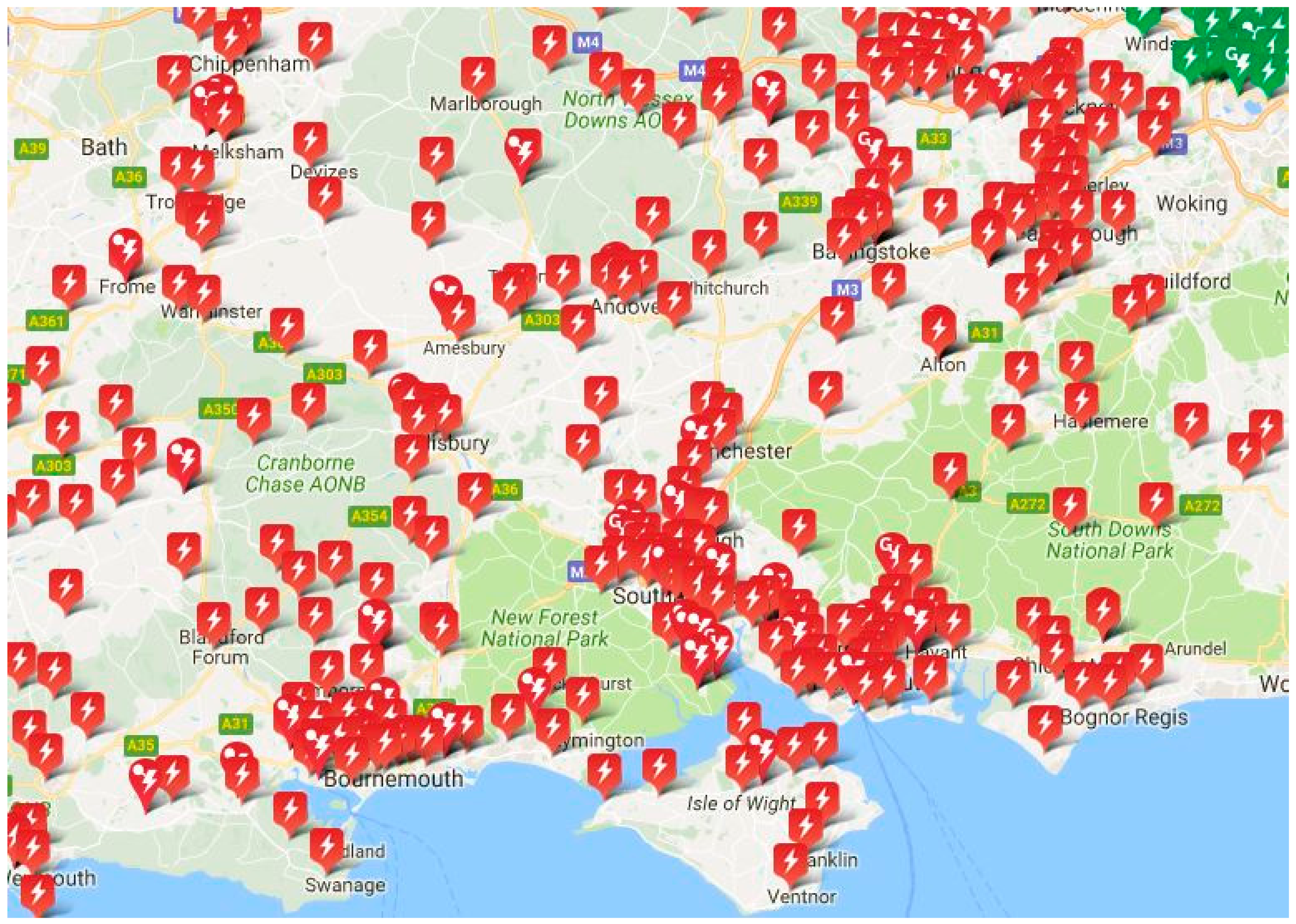
The limitations within a real grid system can be more complex than observed in simulations and could arise from several sources. Challenges stemming from voltage violations, thermal overload and unprecedented faults have forced authorities to place restrictions on the further connection of renewable energy systems in the grid in Southampton (South of England). The Southern and Scottish Electricity Network has identified some substations as zones that can only accommodate renewable energy injections after substantial grid reinforcement has been conducted. Figure 9 shows the substations around Southampton that have been identified to have constraints regarding further renewable energy injection.
Cities such as Portsmouth, Bournemouth and Southampton did not have any renewable energy restrictions since they were not overloaded. However, most parts of the cities have established their loading limits and have, therefore, been subjected to restrictions on the further injection of renewable energy plants.
According to data from the Western Power Distribution [61] in South-West England, most of the 33 kV lines have issues of voltage limit violations, with a few lines thermally overloaded. Fault level issues are common in substations across Exeter. In 2016, a statement was issued by the Western Power Distribution authorities on the state of the 132 kV line, including the constraints emanating from the capacity of the line. At the time, the generation capacity of the south-west area was 1.95 GW against an energy demand of 0.98 GW during summer. This meant that the generation was far more than the demand and the sole 132 kV line connecting several locations in the area was going to be thermally overloaded. As a response to this situation, the Western Power Distribution Company in collaboration with the NGEL (Nation Grid Electricity Transmission) began transmission line reinforcement in the area and there is a ban on further connection of distributed renewable plants for 3–6 years. However, this solution is not sufficient when one considers the benefits of renewable energy. Thus, a solution that permits the further connection of renewable energy plants into a network that is constrained, without raising the required size of the transmission and distribution grid, is urgently needed.

5.2. Case of Greece

In a medium-voltage network in Greece, the authors [62] examined the impact of the penetration of three types of distributed renewable energy resources on power losses, currents, voltage waveform and short-circuit variations of the network using the NEPLAN software. The researchers used predetermined capacities of hydroelectric generators, PV units and a wind energy plant with sizes of 0.24 MW, 2.7 MW and 4 MW, respectively. The DG units were coupled at remote locations from the MV busbars of the main substation and the varied penetration of the DG units had a significantly negative effect on the voltage waveform of the network. Although the authors explored the option of improving the power factor of the DG units in order to maintain the voltage profile within acceptable limits, this, however, did not resolve the issue as the voltage profile was improved only slightly. Moreover, there were discrepancies between the short-circuit level of the feeding substation’s MV busbars obtained during the simulation and the design network value, since the highest obtained value did not exceed the design value. The authors’ major conclusion was that the indiscriminate placement of DG units into the grid not only caused grid instability, as previously discussed, but could also trigger the violation of certain technical parameters in the network. As a recommendation to avoid future network failures, intensive analysis using suitable tools should be conducted, before any attempt to inject DG units into the network.

5.3. Case of Portugal

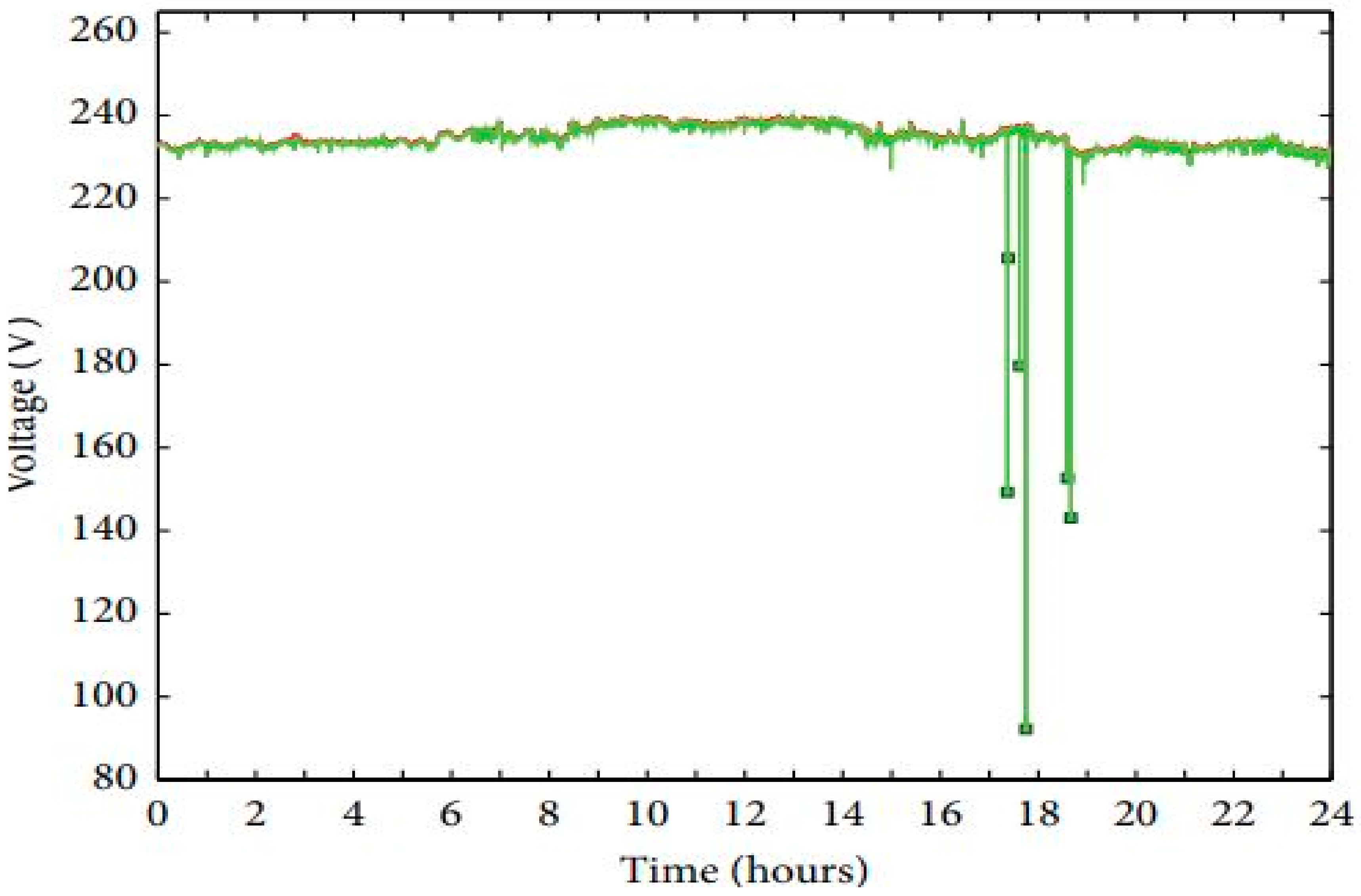
In research conducted on two real-life grid-connected PV systems in rural Portugal [62], the authors sought to investigate the impact of the PV systems on the voltage, frequency and harmonics in the network. They used a voltage-recording device (Fluke VR1710) to monitor and collect data on the evolution of voltage over a period of time, which were to be used for subsequent analysis. After analysis, it was observed in one of the facilities that voltage dips were common in the evening (see Figure 10): up to seven voltage dips were recorded and the most significant case showed an extremely low voltage value below 100 V, which was almost 60% lower than 230 V (rated voltage), violating the European Standard EN 50160 limit. Figure 10 shows the voltage variation in the network within 24 h.
In addition, it was observed in one of the facilities under study that the voltage profile showed several voltage surges during the daylight period (see Figure 10), with 9634 swells recorded. The maximum recorded voltage was 260.75 V, which was 3.06% greater than the limit enforced by the European Standard. Voltages outside of the range of 90–110% are intolerable according the European Standard [63]. Figure 11 shows the changes in voltage in the network.
The authors concluded that grid-connected PV systems will experience a situation of voltage rise as a result of a decrease in the total connected load, and this voltage rise may reach undesirable limits such that it could hinder the interconnection of DG units in the grid. The frequency of occurrence of these voltage violations decreases the quantity of power supplied to the grid (the inverter only connects to the grid when frequency and voltage are within acceptable limits), implying a loss in income and rendering the PV system not economically viable. Moreover, the intensity of the voltage variations imposed on the grid, around the interconnection point, causes increased voltage contamination, which in turn reduces the power quality. When the low-voltage network operates at an appropriate voltage and frequency, the inverter linking the PV system to the grid connects through its AC output, synchronizes and starts delivering power. Once this happens, the voltage increases and reaches a voltage limit above which the inverter becomes disconnected. There is usually a voltage increase because the loads near the PV to the grid connection point are relatively low. This process is continually repetitive, initiating voltage fluctuations (voltage rises as the inverter connects to the grid and starts dropping once the inverter disconnects).

5.4. Case of Pakistan

A case study on the 132 kV substation in Layyah, Pakistan, which experienced issues of active/reactive power losses, poor power factor, low voltage at the customer end and overloaded transformers/distribution lines, was conducted by [64]. After an initial simulation using the ETAP software on the existing system without DG unit injection, the results showed that 23 transformers and 38 distribution lines were overloaded, explaining the frequent power outage experienced by inhabitants. While there were significant power losses in transformers/distribution lines, the power factor was fluctuating around 0.7 and the voltage obtained was 300 V, which was far less than the nominal voltage of 380 V. Figure 12 shows a simulated feeder with overloaded lines and transformers.
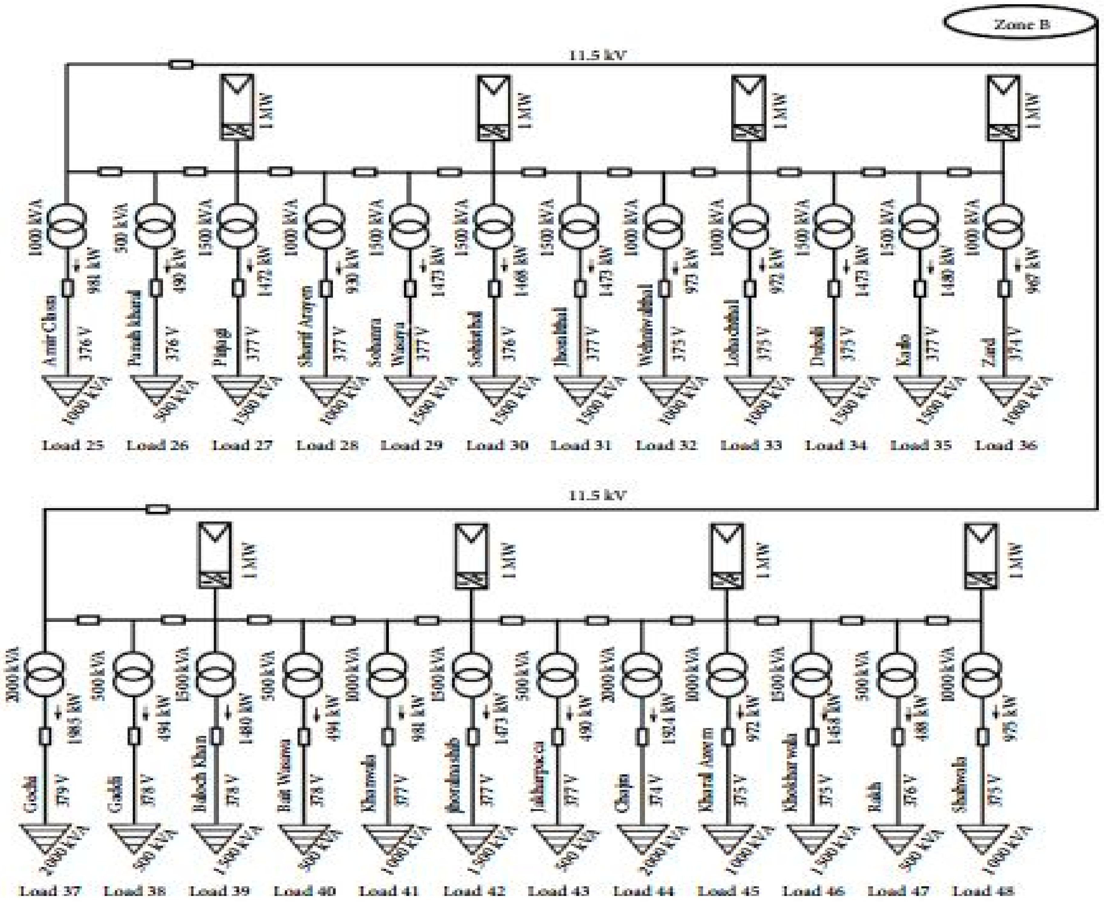
After adding the solar DG units and replacing some transformers and distribution lines with those having improved capacity, it was observed that the voltage returned to approximately 380 V with a unity power factor. There were equally reduced power losses in the network. Figure 13 shows a schematic of the simulation after DG injection with no voltage violations or overloads.
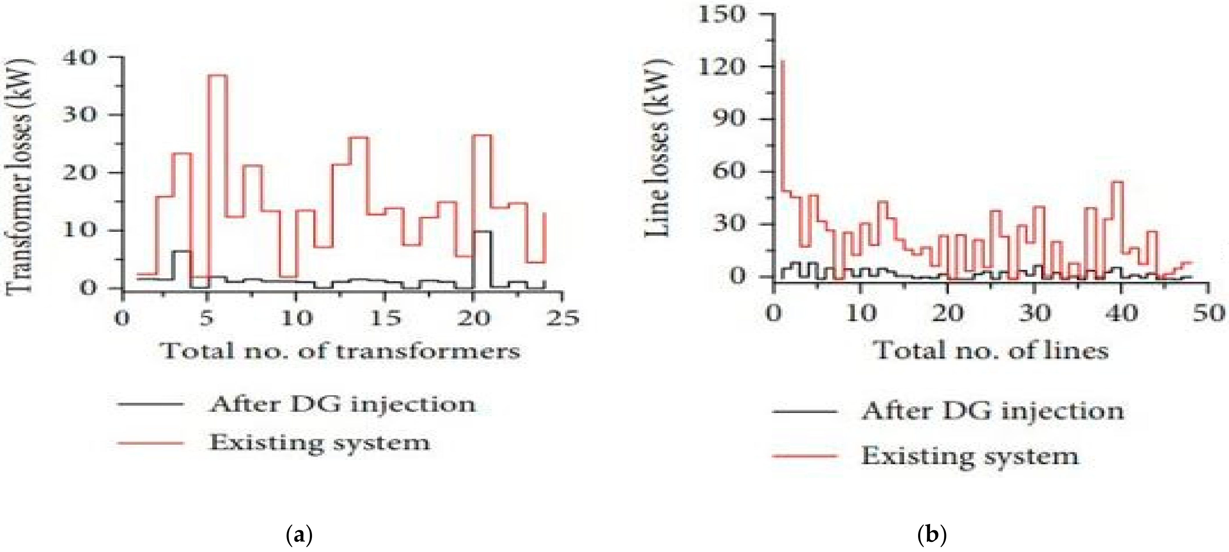
Figure 14 shows a plot of the transformer and line losses obtained before and after the injection of the solar PV system. The plots show significantly reduced power losses both in the transformers and the lines as a result of the PV system injection in the network. This is because the connection of a distributed solar PV system in the network helps to power some of the loads, which reduces the burden on the transformers. At the customer end, solar PV systems were connected to solve the issues of high power demand, voltage fluctuation and poor power factor. When installed close to the users, they help to balance the power deficit and reduce line losses.
Similarly, as the DG units were injected, the power factor and voltage were improved. Figure 15 shows a plot of the power factor and voltage variations before and after the injection of the PV system. These two quantities became more stable with the addition of the DG units. Figure 15 shows the variation in the power factor and voltage before and after DG injection.

5.5. Case of Maryland, USA

A renewable energy integration study that attempted to resolve the issues involved in injecting high distributed solar PV penetration in the grid is presented in [65]. This was an initiative of the US Department of Energy (DoE), and the study identified the components needed to mitigate issues that arise as a result of high penetration of renewable energy systems. The research acknowledged that solar PV injection, while serving part of the loads, would also cause reverse power flow in the distribution network. This could further lead to undesired high voltages, more short circuit scenarios, faulty protection coordination and improper functioning of control devices. The study proposed the regulation of the reactive power produced as a solution to mitigate the problem of reverse power flow. However, this is a challenging task to accomplish without having to regulate the energy produced by the solar PV system, and hence alternate methods need to be developed to address the issue of reverse power flow.

5.6. Case Studies of DG Being Used to Resolve Grid Turbulence

In order to handle grid challenges that occur as a result of high penetration of renewables, a number of solutions have often surfaced in the literature on this subject. These methods are compensation of reactive power through controllers [66,67], the use of storage systems in the network [68,69,70,71], control techniques that mimic the operation of synchronous generators [72] and the management of changes in the power demand of thermostatic loads [73,74].
In order to reduce the expense on ageing grid infrastructure, a 2 MW solar PV system was installed in Montgomery County, Maryland, USA. This DG unit provides critical services such as running the transportation systems, managing emergency services and providing an internal security system for the county [69]. The installation of the solar PV was one of the measures to guarantee the resilience of critical municipal services in the course of extensive grid instability and was developed in collaboration with the Duke Energy utility, which is responsible for energy distribution in the county. It has been reported that the installed DG unit led to USD 4 million savings, which would have been used to upgrade the aging LV/MV electrical network. This distributed solar PV shows how distributed generation can benefit both the utility and customers as it helps to develop mutually cost-effective electricity tariffs.
Three DG units played a leading role in the restoration of Japan’s grid after the earthquake that occurred in East Japan in 2011. These DG units continuously supplied inhabitants with reliable power years after their recovery from this disaster [70]. This demonstrates the DG units’ ability to constantly provide electricity to the communities that they serve, even when the central grid has collapsed. The reliability level increases even further in times where the central grid is functioning.

5.7. Review on Ideal Test Grid

In an attempt to investigate the effects of DG on the enhancement of active power and the reduction of power losses, the researchers in [60] used an extensive radial distribution network and the MatLab application to conduct a sensitivity study. They showed that losses in the distribution network could be minimized by optimizing the connection point, capacity and operation of the distributed generator. They equally argued that optimally placing DG units in the power grid provides active support to the network, as opposed to FACTs (Flexible Alternating Current Transmission Systems) devices, which provide only passive support. These DG units, when installed in the grid, could greatly improve the voltage profile to as much as twice or thrice that obtained from the injection of passive reactive power through a capacitor bank. While this work was mainly aimed at minimizing the power losses and optimally determining the DG capacity, the model showed the relationship between power losses and DG current injection. However, the proposed model was established considering load features and using a constant current approach.
Ajit Kumar et al. [62] considered the impact of large-scale solar PV systems on an IEEE 9-bus test feeder using the ETAP software. They injected solar PV power in steps of 10% penetration in buses that were identified to be load buses while monitoring the power loss, voltage profiles and the transient stability of the network. They observed that the voltage profile improved with the increase in penetration but later started dropping beyond a certain penetration percentage. At the point where the voltages started reducing, the power losses in the line were increasing. Some lines experienced reverse power flows when penetration levels were further increased, necessitating an impact study on transmission line loading when conducting network planning. Moreover, the rate of voltage variations depended on the bus in which the solar PV system was connected. Transient stability analysis showed that the voltage magnitudes, rotor angle and synchronism were the most negatively affected parameters at a high solar PV penetration level and the authors recommended in-depth transient studies in order to maintain grid stability during fault phenomena. However, the researchers used an IEEE 9-bus test feeder with ideal parameters, and conducting a similar study on a real-life system may uncover other challenges.
The assessment of the impact of distributed hybrid wind–solar PV penetration on an IEEE 30-bus test feeder was conducted using the ETAP Software [47]. The authors studied the impacts of the operation of this hybrid system with respect to voltage stability, control and the level of harmonic distortion in the network. After injecting the hybrid wind–solar PV system in the network, the transient effects of bus faults observed were lesser than those obtained when there was no renewable energy injection. However, the hybrid wind–solar PV had introduced some voltage harmonics, which extended over the entire network, although the generated harmonics were within acceptable limits stated by different international standards.
The authors in [75] used DG injection to assess the impact of line losses on a power distribution network. Load flow study at steady state was applied to examine the various voltage profiles and line losses throughout the DG injection process. The DG technologies used in this study were solar PV, wind turbine and a micro-hydro system. The authors assessed four different scenarios starting with the grid system without DG injection, followed by the addition of solar PV. Thereafter, the second scenario involved the interconnection of the wind plant, while micro-hydro injection to the network was the third and fourth scenario. The results showed that the micro-hydro power interconnection into the network gave a relatively small power loss reduction and an improved voltage waveform. However, the amount of power loss reduction and voltage profile improvement was negligible.
While proposing a new approach in assessing the impact of solar-based DG units, the researchers in [76] provided insights into the issue of reverse power flow that can occur during solar PV penetration into the grid. The challenge of reverse power flow would adversely affect the coordination of protective devices and voltage control and this situation could occur at feeder/substation levels. In distribution feeders where there is a unidirectional flow of power, the situation could be serious as it can increase over-current production. The authors recommended the control of the voltage through voltage regulators, which can permit a bidirectional flow of power. However, the installation of bidirectional converters within a pre-existing grid could be costly and, therefore, other cost-effective methods need to be developed to mitigate the challenge of reverse power flow in a power grid.

5.8. Lessons from Successful Countries Integrating Distributed Energy Sources

There are several hands-on measures to integrate distributed renewables economically by enhancing the operating practice and redesigning the electricity market, as observed in some countries. The National Renewable Energy Laboratory (NREL), in their report, argued that more financial resources are required to drive the new energy transition [77] and the few successful experiences below have shown that issues of the integration of variable renewables, such as rising curtailment levels and reserve capacity limits, hardly occur when appropriate measures are proactively implemented. Below are some cases of the successful implementation of renewable energy integration strategies in real-life power grids.

5.8.1. Case of Italy

The year 2018 witnessed a rise in installed solar PV (20 GW) and wind farms (10 GW) in the Italian electricity grid, which initially caused grid congestion and undesired power curtailment. Power system operators have, since then, implemented suitable measures such as dynamic line rating (DLR) to reduce the power curtailment challenge. The DLR is a technique that robustly adjusts the ampacity (current capacity) of transmission lines based on atmospheric conditions such as surrounding temperatures, solar irradiance and wind velocity [78]. This method is relatively cheaper and has greatly reduced power curtailment levels in Italy from 1% to 2% within a short period, and this has remained nearly the same since then, with the support of other strategies such as grid extension and smart grid development. In addition to developing a power infrastructure that is able to accommodate the rising capacity of distributed renewables, the smart grid scheme must facilitate the replacement of the operating coal plant in Puglia [79]. Within this framework, the use of synchronous compensators has facilitated the abandonment of some coal plants in Sardinia, which were regarded as critical to grid stability, helping operators to save millions of euros in expenses [78]. Figure 16 shows the electricity generated from wind and solar sources together with the power curtailment levels experienced from 2009 to 2017 in the Italian power network.

5.8.2. Case of Germany

Renewable penetration in the German electricity grid has increased to the point where 65% of power demand was provided by installed renewables for a whole week in 2018. Moreover, renewable power constituted 90% of the overall electricity usage on 3 March 2019 (windy Sunday) [81]. This rising penetration level, however, exerts stress on the power system infrastructure.
The power network in Germany has been stabilized through the use of conventional power plants and the export of excess power to neighboring countries such as Austria. Despite this, there have still been voltage fluctuation issues owing to the under-capacity of the transmission network, and operators have opted for re-dispatching power. These issues have continued over the years and mostly occur when there is grid congestion within the north to south corridor when generators are turned on to supply the south/west region, meeting demand that was formerly planned to be met using wind farms from the north [78]. The cost of re-dispatching rose to EUR 412 million in 2015, approximately tripling that of 2010, while, between 2017 and 2018, re-dispatching costs dropped from EUR 391 million to EUR 351 million, with prospects of further reduction as new lines are connected to the network. There has been an increase in transmission line installation from 150 to 1100 km and this has positively impacted the power grid in Germany [82].

5.8.3. Case of China

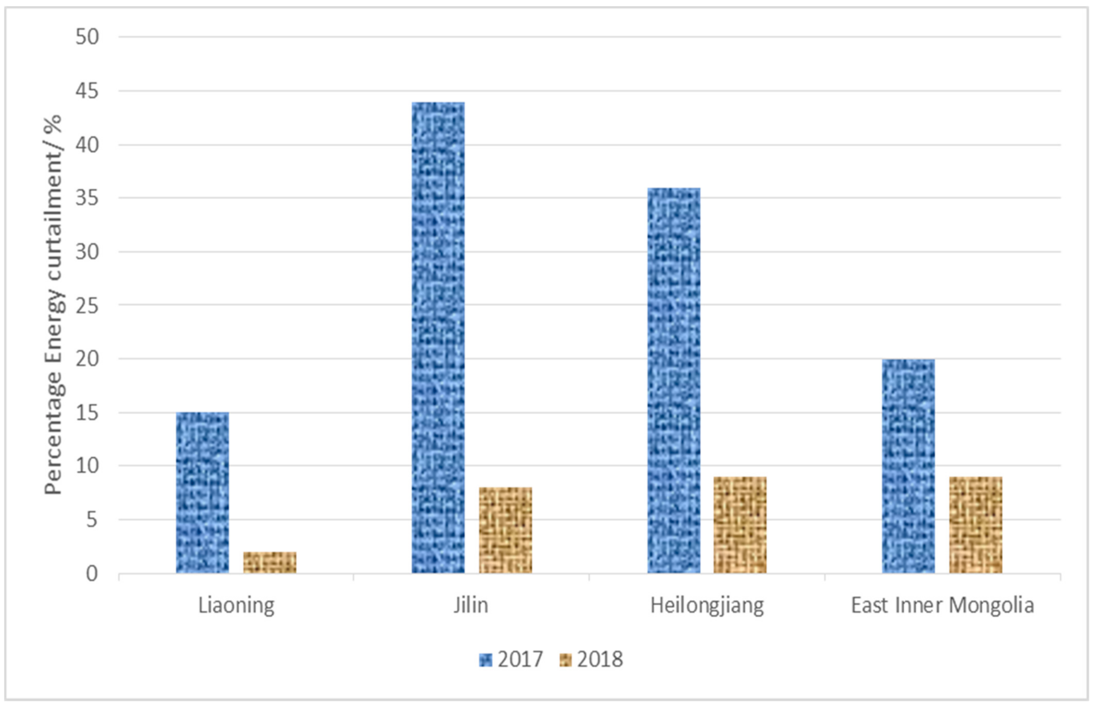
China has equally witnessed a rise in the penetration of variable renewables and is actively involved in high power curtailment in order to manage this increase in electricity production. However, several measures have been applied in the Chinese grid to effectively integrate the rising penetration of solar and wind, thereby significantly minimizing curtailment levels (Figure 17). The level of curtailment from installed wind systems was reduced from 13% to 7% between 2017 and 2018, while installed solar PV systems witnessed a reduction of 5.8–3% within the same period [78].
Coal plants inhibit flexibility in the grid and, therefore, limit the integration of variable renewables. As a mitigation measure, there has been intensive retrofitting of coal plants by authorities and this method has been the most feasible means of adding flexibility at a lower cost compared to other methods such as open-cycle gas turbines or pumped storage [83]. Moreover, financial incentives have helped power-generating units to improve their flexibility and compensate for revenue losses [78]. Figure 17 shows the percentage wind curtailment in Northeast China within the first quarter of 2017 and 2018.
China has adopted reinforcement of the grid and other measures that promote efficient usage of grid infrastructure, such as implementing a mechanism for reserve sharing in regional electricity grids, real-time synchronization and electricity trading points around the country. In addition to prioritizing the deployment of variable renewable projects since 2016, China equally started an annual robust risk alert system to stop further injection of wind power into areas in the grid with constrains, until required actions are taken, conveying investments to sections of the grid that are equipped for additional variable electricity [84].

6. Merits of DG Integration into the Grid

Due to the numerous merits of DG on the grid, there is growing interest from countries through their regulations to increase DG interconnection into the grid. The advantages become even greater if the DGs are from renewable sources, where additional merits such as a reduction in emission levels and capital cost of investment on an RE system as compared to conventional fossil fuel-based energy production are observed [8]. Generally, the injection of electricity from DGs (renewable and non-renewable) into the central grid provides numerous benefits, such as minimizing real power losses, voltage stabilization, grid stability, system reliability, peak demand curtailment, harmonic pollution reduction, reactive power support, frequency control and generation cost reduction. The merits are briefly discussed below.

6.1. Peak Demand Curtailment

Because distributed generators (DGs) are mostly located around end users, they could offset the electricity demand during peak periods and help to decongest the grid. This will avoid situations that could cause instabilities and hence improve the reliability of the grid. The quantity of peak demand offset depends on the capacity of DG, its pattern of operation and the feeder demand profile [29]. When a DG plant is operated in a way that curtails peak demand on a substation, this reduces the need for routine maintenance and increases the components’ lifetime while deferring transmission and generation capacity expansion.

6.2. Reduction of Power Losses in the Network

Due to the fact that most DGs are installed near load centers, where the power produced does not have to be conveyed through long transmission, power losses are greatly reduced [85]. Therefore, the power is easily delivered where it is generated so that it does not need to be evacuated from the main grid with high power losses.

6.3. Frequency Regulation

Some countries and professional bodies, such as the IEEE, have set standard frequency ranges for DG interconnection to the distribution system. These standards offer a range of bounded frequency ranges in which DGs must operate, outside of which the DG unit will be automatically disconnected from the network.
There are some DG technologies that offer frequency regulation functionality to the grid by adjusting the frequency depending on the situation. This is common with combustion turbines whose speed of rotation can be regulated to match the desired frequency. In the event of the violation of frequency limits, the system should trip and the net effect of DG tripping could, at higher penetration levels, cause a situation of underfrequency [86].
The use of standard inverters such as the IEEE 1547, which allows a wider range of frequency and voltage, could mitigate issues of accidental voltage and frequency trips. Moreover, smart inverters could be used to lessen the impact of DGs on the frequency and hence offer frequency support and help to evade DG tripping [87].

6.4. Voltage Stabilization

When real power is added or reactive power is utilized in the grid, the voltage waveforms and the load factor of the network are improved [28,85]. DGs are capable of providing real power and consuming reactive power and, hence, support the voltage profile and load factor of the network. However, the ability of the DG plant to perform these functions will depend on the connection point and the capacity of the DG plant.

6.5. Less Risk of Terrorism

The grid can accommodate DGs in large numbers of small geographically scattered generators, unlike the huge, centralized power plants that can cause a large section of the network to be disconnected if attacked by terrorists. The United States Department of Homeland Security has identified the electricity grid as a critical infrastructure and has recommended DGs as sustainable ways of reducing the susceptibility of the grid to terrorism [88,89]. This is justified by the fact that DGs supply electricity to critical facilities in periods of extensive power disruptions. Terrorist attacks on a major generator in a centralized grid, in the absence of DGs, could lead to large-scale outages.

6.6. Shelving of Network Upgrade

This is the ability to postpone the investment needed to reinforce the transmission line, feeders and transformers as a result of DG integration [28]. Since most DGs are connected around load centers, power flow from the central grid is less because the DG plant offsets part of the demand. The demand curtailment defers the need to upgrade the network and install an additional conventional power plant. For grid operators, DGs could possibly assist in deferring future transmission line expansion plans, hence minimizing operation and maintenance costs.

6.7. Improved Reliability and Security of Supply in the Network

DGs can help in supporting the main grid in meeting demand reliably and could be beneficial to critical loads such as telecommunication systems, which require power supply with high reliability [90]. The rise in DG penetration coupled with intelligent systems could help to improve the security supply as it will reduce the dependence on conventional energy sources by exploring other renewable sources.

6.8. Delivery of Ancillary Services

Ancillary services are important in operating a reliable power system. Utility companies could install DGs in order to provide auxiliary services such as reactive power support, back-up systems and spinning reserves [91]. This means that they could be used as standby to provide power when there is an emergency or power outage. Researchers have examined the potential of using DGs in auxiliary services and found that DGs could economically contribute to the delivery of auxiliary services.

6.9. Economic Viability of DG Projects

Distributed generation has the potential to reduce customers’ electricity bills and deliver power with improved efficiency [9]. Electricity tariffs usually take into consideration the inefficiencies in the transmission and distribution network, where power losses occur, and this situation is intensified when the transmission distance is long. Hence, distributed generation could make electricity tariffs cheap and affordable since energy will be generated near load centers, but this is not obtainable with a centralized electrical network, where power is transported over a long distance to consumers, incurring huge line losses. In a liberalized energy market, where investors are allowed to install their own DGs, more power could be made available as investors respond to varying market forces; hence, system flexibility and competition would be increased, which could greatly reduce electricity prices.
The installation of DG plants requires a relatively short duration and less investment as opposed to that of large power plants in the main grid, and the modular nature of DGs makes their assembly very easy. DGs are not interdependent and cannot be influenced by the operation of other generators, such that the failure of one cannot affect the other. The capital cost is greatly reduced since the construction of DGs will lead to deferral in the construction of transmission infrastructures. In areas where there are penalties for environmental pollution, distributed renewable energy systems with small emissions will assist in lowering the accompanying cost of environmental penalties.

7. Discussion and Future Perspectives

Most of the studies have considered power losses and voltage profiles as major parameters in studying the behavior of the grid in the wake of the addition of distributed power sources. Some researchers have added transient stability and thermal limits as constraints in their findings and this has further shed light on the subject of power system stability. Noteworthy is the fact that most of the test systems used by researchers are test beds developed by IEEE to mimic the behavior of a grid system, and it is difficult to find research work on real-life power networks addressing these issues. Therefore, more studies need to be conducted on existing power systems in order to elucidate these challenges, which are most often overlooked by simulation studies on ideal networks.
With the growing advancement in research on renewable technologies, the cost of these systems has dropped considerably within the last 10 years. The International Renewable Energy Agency (IRENA) reported that the electricity cost from solar PV was reduced by approximately 75% between 2009 and 2018, while the cost of power generated from onshore wind farms dropped by around 25% within the same period [92]. Consequently, there is a favorable business opportunity for electricity generation through distributed renewables today and, henceforth, attention should gravitate towards reducing the integration cost for these equipment. Apart from the cost factor, efficiently managing huge amounts of variable renewables requires considerable flexibility in all segments of the energy value chain, from electricity generation to power transmission/distribution systems, storage and, even more importantly, flexible demand.
The lessons from the successful experiences of some countries are essential and offer a realistic analysis that could help power stakeholders in other countries to create more resilient renewable integration systems with high technical efficiency and improved cost-effectiveness. Electricity regulators elsewhere should exploit the successful measures of integrating large-scale renewables to spearhead a swift renewable energy transition while maintaining high electricity reliability and stable electricity tariffs for all users. However, due to the diverse nature of countries, the intensity of challenges and associated measures may vary since they all depend on a number of factors. Hence, the renewable energy transition must be tackled using a multidimensional approach. Even though no two nations are identical, and different countries take different pathways in their electricity evolution, successful measures previously used possibly will be a perfect match for nations with similar characteristics.
From the review, we observed that technical solutions to renewable energy integration issues are nearly always available, but the drawback is principally economic instead of technical. Consequently, the highest ideal renewable penetration level is one where any additional cost will be more than the benefits of an extra DG unit and thus no additional DG capacity is economically needed. Future research should focus on minimizing the cost of integrating these systems.

8. Conclusions

The growing prospects in distributed generation (DG) to grid interconnection and decarbonization of power systems around the world indicate that DGs, especially renewables-based, could make a significant contribution to the future of power generation. Policymakers, grid operators, power system developers and consumers are the stakeholders whose interests DG integration must address. Even though the integration of DG into the power grid has benefits, such as line loss reduction, improved grid flexibility, cost-effective energy production and minimization of the tendency to invest in additional grid assets during capacity expansion, several issues arise when these systems are added to the network. The paper has pointed out the current industry practices, weaknesses of these practices, issues, potential solutions and future considerations concerning the integration of DGs into the electricity grid. The connection point where the distributed renewables are injected into the grid remains a significant issue to be resolved by grid operators before any integration attempt. The study has also discussed the impacts of DG location on the system voltage. Most of the available methods and research works on DG integration have proven to be promising, with the potential to disrupt the technology landscape in the near future. Nevertheless, the constraint of power system stability remains paramount in the integration of DGs, especially variable renewables, in the power network, and innovative integration tools should be employed before deployment in order to mitigate any possible disturbance in the network.

Author Contributions

Conceptualization C.D.I. and S.G.; methodology and validation, E.E.-D. and E.T.; investigation, C.D.I.; writing—original draft preparation, C.D.I.; writing—review and editing, C.D.I.; supervision, S.G., E.T. and E.E.-D. All authors have read and agreed to the published version of the manuscript.

Funding

This research received no external funding.

Institutional Review Board Statement

Not applicable.

Informed Consent Statement

Not applicable.

Acknowledgments

This study was supported by the Regional Center for Energy and Environmental Sustainability (RCEES) of the University of Energy and Natural Resources, Sunyani-Ghana and it is therefore acknowledged.

Conflicts of Interest

The authors declare no conflict of interest.

References

  1. Carley, S. Distributed generation: An empirical analysis of primary motivators. Energy Policy 2009, 37, 1648–1659. [Google Scholar] [CrossRef]
  2. Allan, G.; Eromenko, I.; Gilmartin, M.; Kockar, I.; McGregor, P. The economics of distributed energy generation: A literature review. Renew. Sustain. Energy Rev. 2015, 42, 543–556. [Google Scholar] [CrossRef] [Green Version]
  3. Renewable Energy Policy Network for the 21st Century (REN21). Renewables—Global Status Report; REN21 Secretariat: Paris, France, 2017. [Google Scholar]
  4. International Renewable Energy Agency (IRENA). Report on Renewable Energy Capacity Statistics; (IRENA): Abu Dhabi, UAE, 2017. [Google Scholar]
  5. Wasiak, I.; Hanzelka, Z. Integration of distributed energy sources with electrical power grid. Bull. Pol. Acad. Sci. Tech. Sci. 2009, 57, 297–308. [Google Scholar] [CrossRef] [Green Version]
  6. Luhmann, T.; Wieben, T.E.; Treydel, R.; Stadler, M.; Kumm, T. An approach for cost-efficient grid integration of distributed renewable energy sources. Eng. Sci. Press 2015, 1, 447–452. [Google Scholar] [CrossRef] [Green Version]
  7. Kempener, R.; Komor, P.; Hoke, A. Smart Grids and Renewables—A Guide for Effective Deployment; International Renewable Energy Agency (IRENA): Abu Dhabi, UAE, 2013. [Google Scholar]
  8. Muntathir, A.T.; Chokri, A.B. Optimal PV penetration for power losses subject to transient stability and harmonics. Proc. Comput. Sci. 2020, 175, 508–516. [Google Scholar]
  9. Zahedi, A. A review of drivers, benefits, and challenges in integrating renewable energy sources into electricity grid. Renew. Sustain. Energy Rev. 2011, 15, 4775–4779. [Google Scholar] [CrossRef]
  10. Soroudi, A.; Ehsan, M.; Caire, R.; Hadjsaid, N. Possibilistic evaluation of distributed generations impacts on distribution networks. IEEE Trans. Power Syst. 2011, 26, 2293–2301. [Google Scholar] [CrossRef] [Green Version]
  11. Lopes, V.S.; Borges, C.L.T. Impact of the combined integration of wind generation and small hydropower plants on the system reliability. IEEE Trans. Sustain. Energy 2015, 6, 1169–1177. [Google Scholar] [CrossRef]
  12. Adil, A.M.; Ko, Y. Socio-technical evolution of decentralized energy systems: A critical review and implications for urban planning and policy. Renew. Sustain. Energy Rev. 2016, 57, 1025–1037. [Google Scholar] [CrossRef]
  13. Colmenar, S.A.; Reino, R.C.; Borge, D.D.; Collado, F.E. Distributed generation: A review of factors that can contribute most to achieve a scenario of DG units embedded in the new distribution networks. Renew. Sustain. Energy Rev. 2016, 59, 1130–1148. [Google Scholar] [CrossRef]
  14. CIGRE Study Committee. Impact of Increasing Contribution of Dispersed Generation on the Power System; International Council on Large Electricity Systems (CIGRE): Paris, France, 1998. [Google Scholar]
  15. Ajit, K.; Selvan, M.P.; Rajapandiyan, K. Grid Stability Analysis for High Penetration Solar Photovoltaics. NIT Trichy: Thuvakudi, India, 2016. [Google Scholar]
  16. Archana, R.; Subramaniya, S.A. A perspective analysis for the impact of PV and wind hybrid distributed generation using eTAP. Int. J. Adv. Res. Electr. Electron. Instrum. Eng. 2018, 7, 2023–2029. [Google Scholar]
  17. Bank, J.; Mather, B.; Keller, J.; Coddington, M. High Penetration Photovoltaic Case Study Report; Technical Report; National Renewable Energy Laboratory: Denver, CO, USA, 2013.
  18. Belcher, B.; Petry, B.J.; Davis, T.; Hatipoglu, K. The effects of major solar integration on a 21-Bus system: Technology review and PSAT simulations. In Proceedings of the SoutheastCon 2017, Concord, NC, USA, 30 March–2 April 2017. [Google Scholar]
  19. Chiradeja, P.; Ramakumar, R. An approach to quantify the technical benefits of distributed generation. IEEE Trans. Energy Convers. 2004, 19, 764–773. [Google Scholar] [CrossRef]
  20. Ochoa, L.F.; Padilha-Feltrin, A.; Harrison, G.P. Evaluating distributed generation impacts with a multiobjective index. IEEE Trans. Power Deliv. 2006, 21, 1452–1458. [Google Scholar] [CrossRef] [Green Version]
  21. Singh, D.; Singh, D.; Verma, K.S. Multiobjective optimization for DG planning with load models. IEEE Trans. Power Syst. 2009, 24, 427–436. [Google Scholar] [CrossRef]
  22. Pepermans, G.; Driesen, J.; Haeseldonckx, D.; Belmans, R.; D’haeseleer, W. Distributed generation: Definition, benefits and issues. Energy Policy 2005, 33, 787–798. [Google Scholar] [CrossRef]
  23. International Energy Agency. Energy Technologies for the 21st Century; IEA: Paris, France, 1997. [Google Scholar]
  24. Ackermann, T.; Anderson, G.; Söder, L. Distributed generation: A definition. Elect. Power Sys. Res. 2001, 57, 195–204. [Google Scholar] [CrossRef]
  25. Dondi, P.; Bayoumi, D.; Haederli, C.; Julian, D.; Suter, M. Network integration of distributed power generation. J. Power Sources 2002, 106, 1–9. [Google Scholar] [CrossRef]
  26. Chambers, A. Distributed Generation: A Non-Technical Guide; Pennwell: Tulsa, OK, USA, 2001. [Google Scholar]
  27. Willis, H.L.; Scott, W.G. Distributed Power Generation; Marcel Dekker: New York, NY, USA, 2000. [Google Scholar]
  28. Khetrapal, P. Distributed generation: A critical review of technologies, grid integration issues, growth drivers and potential benefits. Inter. J. Renew. Energy Dev. 2020, 9, 189–205. [Google Scholar] [CrossRef]
  29. Paliwal, P.; Patidar, N.P.; Nema, R.K. Planning of grid integrated generators: A review of technology, objectives and planning. Renew. Sustain. Energy Rev. 2014, 40, 4557–4570. [Google Scholar] [CrossRef]
  30. Renewable Energy Policy Network for the 21st Century (REN21). Renewables 2019 Global Status Report; REN21 Secretariat: Paris, France, 2019. [Google Scholar]
  31. Renewable Energy Policy Network for the 21st Century (REN21). Renewables 2020 Global Status Report; REN21 Secretariat: Paris, France, 2020. [Google Scholar]
  32. Jain, S.; Kalambe, S.; Agnihotri, G.; Mishra, A. Distributed generation deployment: State-of-the-art of the distribution system planning in sustainable era. Renew. Sustain. Energy Rev. 2017, 77, 363–385. [Google Scholar] [CrossRef]
  33. Van-Thong, V.; Driesen, J.; Belmans, R. Power quality and voltage stability of distribution system with distributed energy resources. Inter. J. Distrib. Energy Res. 2005, 1, 227–240. [Google Scholar]
  34. Singh, D.; Misra, R.K.; Singh, D. Effect of load models in distributed generation planning. IEEE Trans. Power Sys. 2007, 22, 2204–2212. [Google Scholar] [CrossRef]
  35. Iyer, H.; Ray, S.; Ramakumar, R. Voltage profile improvement with distributed generation. IEEE Power Eng. Soc. Gen. Meet. 2005, 3, 1603–1610. [Google Scholar]
  36. Nabavi, S.M.H.; Hajforoosh, S.; Masoum, M.A.S. Placement and sizing of distributed generation units for congestion management and improvement of voltageprofile using particle swarm optimization. IEEE PES Innov. Smart Grid Technol. 2011, 1–6. [Google Scholar] [CrossRef]
  37. Bayer, B.; Marian, A. Innovative measures for integrating renewable energy in the German medium-voltage grids. Energy Rep. 2020, 6, 336–342. [Google Scholar] [CrossRef]
  38. Markiewicz, H.; Klajn, A. Voltage Disturbances: Standard EN 50160 Voltage Characteristics in Public Distribution Systems; European Copper Institute: Brussels, Belgium, 2011. [Google Scholar]
  39. Forum Grid Technology of the VDE. Voltage-Regulated Distribution Transformer (VRDT)—Use in Grid Planning and Operation; Forum Netztechnik/Netzbetrieb im VDE (FNN): Berlin, Germany, 2016. [Google Scholar]
  40. Roy, N.; Pota, H.R. Current status and issues of concern for the integration of distributed generation into electricity networks. IEEE Sys. J. 2015, 9, 933–944. [Google Scholar] [CrossRef]
  41. Bayer, B.; Matschoss, P.; Thomas, H.; Marian, A. The German experience with integrating photovoltaic systems into the low-voltage grids. Renew. Energy 2018, 119, 129–141. [Google Scholar] [CrossRef]
  42. Wang, Q.; Zhang, C.; Ding, Y.; Xydis, G.; Wang, J.; Østergaard, J. Review of real time electricity markets for integrating Distributed Energy Resources and Demand Response. Appl. Energy 2015, 138, 695–706. [Google Scholar] [CrossRef]
  43. Conti, S.; Raiti, S.; Tina, G. Small scale generation effect on embedded on voltage profile: Am analytical Method. IEEE Proc. Gener. Transm. Distrib. 2003. [Google Scholar] [CrossRef]
  44. Mahmud, M.A.; Hossain, M.J.; Pota, H.R. Voltage variation on distribution networks with distributed generation: Worst case scenario. IEEE Sys. J. 2014, 8, 1096–1103. [Google Scholar] [CrossRef]
  45. Mahmud, N.; Zahedi, A. Review of control strategies for voltage regulation of the smart distribution network with high penetration of renewable distributed generation. Renew. Sustain. Energy Rev. 2016, 64, 582–595. [Google Scholar] [CrossRef]
  46. Khalesi, N.; Rezaei, N.; Haghifam, M.R. DG allocation with application of dynamic programming for loss reduction and reliability improvement. Int. J. Electr. Power Energy Syst. 2011, 33, 88–295. [Google Scholar] [CrossRef]
  47. Delfanti, M.; Falabretti, D.; Merlo, M. Dispersed generation impact on distribution network losses. Electr. Power Syst. Res. 2013, 97, 10–18. [Google Scholar] [CrossRef]
  48. Zaheeruddin, M.M. Renewable energy management through microgrid central controller design: An approach to integrate solar, wind and biomass with battery. Energy Rep. 2015, 1, 156–163. [Google Scholar] [CrossRef] [Green Version]
  49. Agah, M.S.M.; Abyaneh, H.A. Distribution transformer loss-of-life reduction by increasing penetration of distributed generation. IEEE Trans. Power Deliv. 2011, 26, 1128–1136. [Google Scholar] [CrossRef]
  50. Agah, M.S.M.; Abyaneh, H.A. Quantification of the distribution transformer life extension value of distributed generation. IEEE Trans. Power Deliv. 2011, 26, 1820–1828. [Google Scholar] [CrossRef]
  51. El-Batawy, S.A.; Morsi, W.G. On the Impact of high penetration of rooftop solar photovoltaics on the aging of distribution transformers. Can. J. Electr. Comput. Eng. 2017, 40, 93–99. [Google Scholar]
  52. Csányi, G.M.; Tamus, Z.Á.; Varga, Á. Impact of distributed generation on the thermal ageing of low voltage distribution cables. In Technological Innovation for Smart Systems; IFIP Advances in Information and Communication Technology 2017; Springer: New York, NY, USA, 2017; pp. 251–258. [Google Scholar]
  53. British Standards Institution (BSI). BS EN61400-21 Wind Turbines: Measurement and Assessment of Power Quality Characteristics of Grid Connected Wind Turbines; BSI: London, UK, 2009.
  54. Latran, M.B.; Teke, A.; Yoldas, Y. Mitigation of power quality problems using distribution static synchronous compensator: A comprehensive review. IET Power Electron. 2015, 8, 1312–1328. [Google Scholar] [CrossRef]
  55. Bizon, N. Effective mitigation of the load pulses by controlling the battery/SMES hybrid energy storage system. Appl. Energy 2018, 229, 459–473. [Google Scholar] [CrossRef]
  56. Brearley, J.B.; Raja, P.R. A review on issues and approaches for microgrid protection. Renew. Sustain. Energy Rev. 2017, 67, 988–997. [Google Scholar] [CrossRef]
  57. Ishchenko, D.; Oudalov, A.; Stoupis, J. Protection coordination in active distribution grids with IEC 61850. In Proceedings of the IEEE PES Transmission and Distribution Conference and Exposition (T&D), Orlando, FL, USA, 7–10 May 2012. [Google Scholar]
  58. Murugan, R.; Ramasamy, R. Failure analysis of power transformer for effective maintenance in electric machines. Eng. Fail. Anal. 2015, 55, 182–192. [Google Scholar] [CrossRef]
  59. Trichakis, P.; Taylor, P.; Lyons, P.; Hair, R. Predicting the technical impact of high levels of small embedded generators on low voltage networks. Renew. Power Gener. 2008, 2, 249–262. [Google Scholar] [CrossRef]
  60. Scottish and Southampton Power Distribution. Generation Availability Map. 2016. Available online: https://ssepd.co.uk/GenerationAvailabilityMap/?mapareaid=1 (accessed on 13 April 2021).
  61. Western Power Distribution. Distributed Generation ehv Constraint Map. 2018. Available online: https://www.westernpower.co.uk/connections/generation/distributed-generation-ehv-constraint-maps.aspx (accessed on 25 March 2021).
  62. Pinto, R.J.C.; Mariano, S.J.P.S.; Maria, R.A.C. Power quality experimental analysis on rural home grid-connected PV systems. Int. J. Photoenergy 2015, 2015, 791680. [Google Scholar] [CrossRef] [Green Version]
  63. European Standard EN 50160 (CENELEC). Voltage Characteristics of Electricity Supplied by Public Distribution Networks; CENELEC: Brussels, Belgium, 2007. [Google Scholar]
  64. Mujtaba, G.; Rashid, Z.; Umer, F.; Baloch, S.K.; Hussain, G.A.; Haider, M.U. Implementation of distributed generation with solar plants in a 132 kV grid station at layyah using ETAP. Int. J. Photoenergy 2020, 2020, 6574659. [Google Scholar] [CrossRef]
  65. Liu, E.; Bebic, J. Distribution System Voltage Performance Analysis for High-Penetration Photovoltaics; OSTI: New York, NY, USA, 2008.
  66. Majumder, R. Reactive power compensation in single-phase operation of microgrid. IEEE Trans. Ind. Electr. 2013, 60, 1403–1416. [Google Scholar] [CrossRef]
  67. Pathak, A.K.; Sharma, M.P.; Gupta, M. Modeling and simulation of SVC for reactive power control in high penetration wind power system. In Proceedings of the Annual IEEE India Conference (INDICON), New Delhi, India, 17–20 December 2015. [Google Scholar]
  68. Miranda, I.; Silva, N.; Leite, H. A holistic approach to the integration of battery energy storage systems in island electric grids with high wind penetration. IEEE Trans. Sustain. Energy 2016, 7, 20775–207785. [Google Scholar] [CrossRef]
  69. Fang, J.; Tang, Y.; Li, H.; Li, X. A battery/ultracapacitor hybrid energy storage system for implementing the power management of virtual synchronous generators. IEEE Trans. Power Electr. 2018, 33, 2820–2824. [Google Scholar] [CrossRef]
  70. Sperstad, I.B.; Korpås, M. Energy storage scheduling in distribution systems considering wind and photovoltaic generation uncertainties. Energies 2019, 12, 1231. [Google Scholar] [CrossRef] [Green Version]
  71. Zeraati, M.; Golshan, M.E.H.; Guerrero, J.M. Distributed control of battery energy storage systems for voltage regulation in distribution networks with high PV penetration. IEEE Trans. Smart Grid 2016, 9, 3582–3593. [Google Scholar] [CrossRef] [Green Version]
  72. Rubino, S.; Mazza, A.; Chicco, G.; Pastorelli, M. Advanced control of inverter-interfaced generation behaving as a virtual synchronous generator. In Proceedings of the IEEE PowerTech, Eindhoven, The Netherlands, 29 June–2 July 2015. [Google Scholar]
  73. Wang, Y.; Xu, Y.; Tang, Y. Distributed aggregation control of grid-interactive smart buildings for power system frequency support. Appl. Energy 2019, 251, 113371. [Google Scholar] [CrossRef]
  74. Wang, Y.; Tang, Y.; Xu, Y.; Xu, Y.L. A distributed control scheme of thermostatically controlled loads for the building-microgrid community. IEEE Trans. Sustain. Energy 2019, 11, 350–360. [Google Scholar] [CrossRef]
  75. Suyono, H.; Hasanah, R.N. Analysis of power losses due to distributed generation increase on distribution system. J. Teknol. 2016, 6, 23–28. [Google Scholar] [CrossRef] [Green Version]
  76. Katiraei, F.; Aguero, J. Solar PV integration challenges. IEEE Power Energy Mag. 2011, 9, 62–71. [Google Scholar] [CrossRef]
  77. National Renewable Energy Laboratory. Grid Integration and the Carrying Capacity of the U.S. Grid to Incorporate Variable Renewable Energy (No. NREL/TP-6A20-62607); NREL: Golden, CO, USA, 2015.
  78. International Renewable Energy Agency. Solutions to Integrate High Shares of Variable Renewable Energy (Report to the G20 Energy Transitions Working Group (ETWG)); IRENA: Abu Dhabi, UAE, 2019. [Google Scholar]
  79. E-Distribuzione. Puglia Active Network: The Project that will make Puglia the First Smart Region in Italy, e-distribuzione SpA. 2019. Available online: www.e-distribuzione.it/it/progetti-einnovazioni/PAN.html/ (accessed on 4 June 2021).
  80. Carlini, E.M. Terna’s Experience on Wind and Solar Energy Integration; Terna: Rome, Italy, 2018. [Google Scholar]
  81. Agora Energiewende. Recent Electricity Data: Power Generation and Consumption; Agora Energiewende: Berlin, Germany, 2019. [Google Scholar]
  82. BNetzA. Quarterly Report on Network and System Security Measures: Full Year and Fourth Quarter of 2018; Bundesnetzagentur: Bonn, Germany, 2019.
  83. Clean Energy Ministerial Campaign. Thermal Power Plant Flexibility—A Publication under the Clean Energy Ministerial Campaign; CEM: Paris, France, 2019. [Google Scholar]
  84. CNREC. China Renewable Energy Outlook 2018—Executive Summary; Energy Research Institute of Academy of Macroeconomic Research, China Renewable Energy Research Centre: Beijing, China, 2018.
  85. Ali, M.E.; Yehia, S.M.; Abou-Hashema, M.E.S.; Amer, N.A.E. Reliability/security of distribution system network under supporting by distributed generation. Insight Energy Sci. 2019, 2, 1–13. [Google Scholar]
  86. Mahat, P.; Chen, Z.; Bak-Jensen, B. Under frequency load shedding for an islanded distributed system with distributed generation. IEEE Trans. Power Deliv. 2010, 25, 911–918. [Google Scholar] [CrossRef]
  87. Institute of Electrical and Electronics Engineers (IEEE). Standard for Interconnecting Distributed Resources with Electric Power Systems; IEEE: Piscataway, NJ, USA, 2003. [Google Scholar]
  88. United States Government Accountability Office. Electricity Grid Cyber Security: DOE Needs to Ensure Its Plans Fully Address Risks to Distribution Systems (GAO-21-81); US GAO: Washington, DC, USA, 2021.
  89. Wintch, T.M. Perspective: Cyber and Physical Threats to the U.S. Power Grid and Keeping the Lights On . U.S. Department of Homeland Security, 2021. Available online: https://www.hstoday.us/subject-matter-areas/infrastructure-security/perspective-cyber-and-physical-threats-to-the-u-s-power-grid-and-keeping-the-lights-on/ (accessed on 4 June 2021).
  90. North American Electric Reliability Corporation. Distributed Energy Resources: Connection Modeling and Reliability Considerations; NERC: Atlanta, GA, USA, 2017. [Google Scholar]
  91. Alejandra, T.; Norberto, M.; Lucas, G.; José, F.R.; Fredy, J.F. Optimal capacity sizing for the integration of a battery and photovoltaic microgrid to supply auxiliary services in substations under a contingency. Energies 2020, 13, 6037. [Google Scholar]
  92. International Renewable Energy Agency. Renewable Power Generation Costs in 2017; IRENA: Abu Dhabi, UAE, 2017. [Google Scholar]
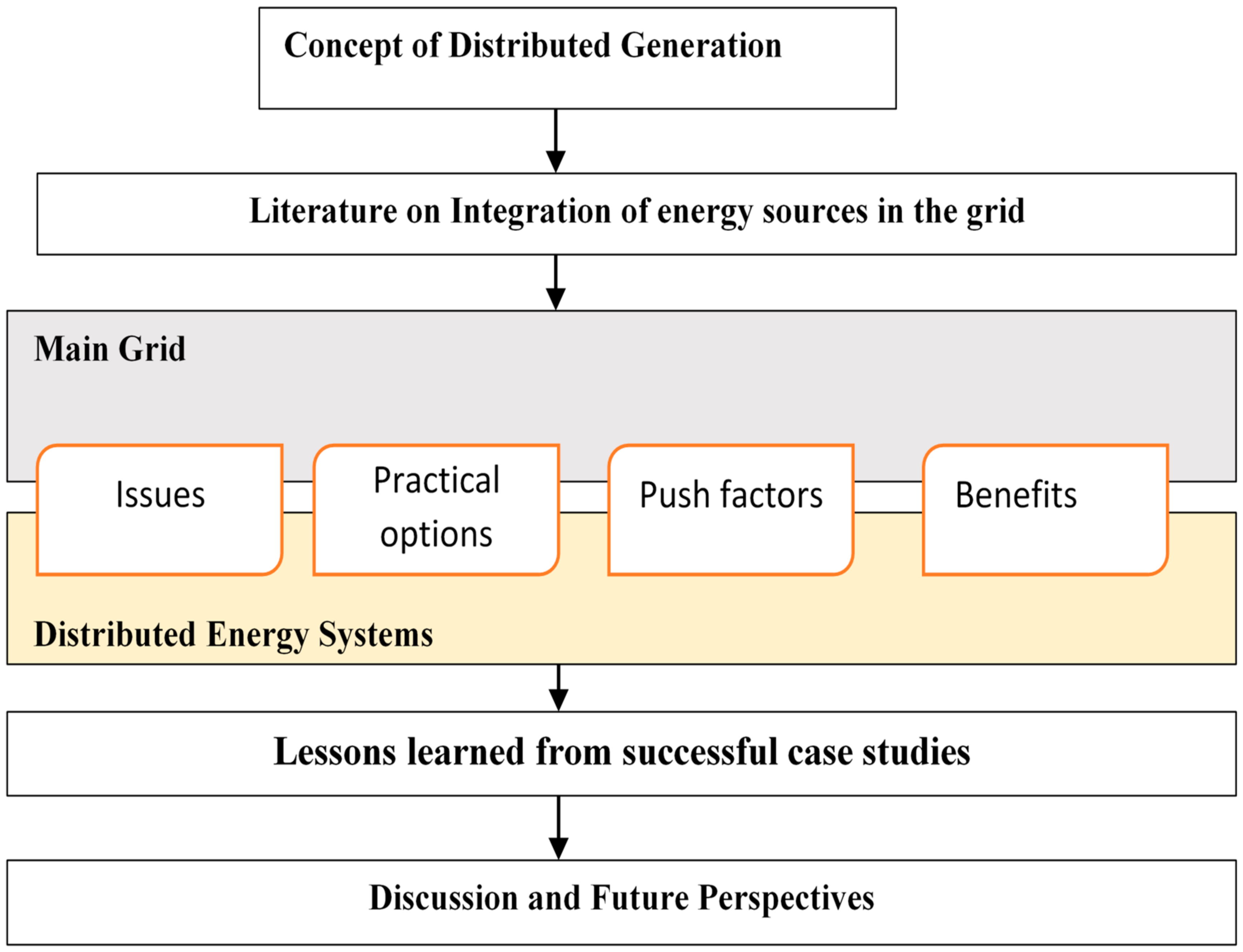
Figure 1. Illustration of the structure of the review paper.
Energies 14 05375 g001
Figure 2. Classification of DG technologies [28].
Energies 14 05375 g002
Figure 3. Illustration of the power system transition.
Energies 14 05375 g003
Figure 4. Solar and wind electricity generation mix from the top 10 countries in 2018 [30].
Energies 14 05375 g004
Figure 5. Net annual additions in electricity production capacity of renewable and non-renewable sources between 2009 and 2019 [31].
Energies 14 05375 g005
Figure 6. Suggested allocation of voltage ranges [39].
Energies 14 05375 g006
Figure 7. Illustration of voltage profile of network before and after RE integration: (a) Voltage profile at LV network with no distributed renewables; (b) Voltage profile at LV network with distributed renewables.
Energies 14 05375 g007
Figure 8. Example of renewable energy power generation patterns [48].
Energies 14 05375 g008
Figure 9. Google map of substations with restrictions (red) and without restrictions (green) on the injection of renewable energy in Southampton, United Kingdom [60].
Energies 14 05375 g009
Figure 10. Voltage profile of the facility for 24 h. The green line shows the lowest voltages obtained, the large green dots indicate the voltage dips, the black line shows the medium voltages, and the red line represents the maximum voltages [62].
Energies 14 05375 g010
Figure 11. The voltage profile recorded in the second facility. The green shows the minimum voltages, the black shows the medium voltages, and the red signifies the maximum voltages [62].
Energies 14 05375 g011
Figure 12. Grid with overloaded transformers and lines in red [64].
Energies 14 05375 g012
Figure 13. Grid with injected PV System and replaced transformers and lines having no overloads [64].
Energies 14 05375 g013
Figure 14. (a) Transformer losses and (b) line losses before and after DG injection [64].
Energies 14 05375 g014
Figure 15. (a) Power factor and (b) voltage before and after DG injection [64].
Energies 14 05375 g015
Figure 16. Wind/solar electricity generation and curtailment in Italy [80].
Energies 14 05375 g016
Figure 17. Percentage curtailment of wind power in northeastern provinces of China within the first quarter of 2017 and 2018 [83].
Energies 14 05375 g017
Table 1. Classification of DGs by some countries/institutions [14,22,24].
Country/InstitutionCapacity of DGLocation of DGMode of Operation
Sweden≤1500 kW--
New Zealand<5 MW--
Australian Energy Market Operator≤30 MW--
International Council on Large Electricity Systems<100 MWMost often coupled to the distribution networkNot managed/dispatched centrally
Bulgarian Energy Holding Company<10 MWConnected to the distribution networkNot managed centrally
Electric Power Research Institute≤50 MWMost often installed near load centers or distribution and medium-voltage (MV) substations-
Gas Research Institute25 kW ≤ X ≤ 25 MW--
England and Wales Electricity Markets<100 MW-Not dispatched at a central point
Estonian Power Markets<50 MWConnected to the distribution network -
Institute of Electrical and Electronics Engineering≤10 MWConnected at any point within the power grid-
Publisher’s Note: MDPI stays neutral with regard to jurisdictional claims in published maps and institutional affiliations.