Abstract
High-order filters, such as LCL, are more commonly employed in grid-connected inverters (GcIs) as an interference element for the better attenuation of switching harmonics. However, LCL filters may have resonance poles and antiresonance zeros in the frequency response with inverter side current. This may affect the stability of the system and limit the control bandwidth with the simple single-loop PI control. This becomes severe with the introduction of grid impedance due to the large distance between renewable energy sources and the power grid. To mitigate this effect, active damping and sensorless damping is preferred with pre-information about grid impedance. In this paper, linear active disturbance rejection control (ADRC) is introduced, first to L filter type GcI and later extended to LCL filter type GcIs with minimum modification. From the frequency analysis, it is shown that the characteristics of the proposed control scheme remain the same even with a change in filter order and grid impedance. The resonance poles and antiresonance zeros in the LCL filter are compensated via the pole–zero cancelation technique. In addition to this, the preserve bandwidth, simple control design, and decoupled current control are also achieved with the proposed method. The robustness of the proposed method is compared with the single-loop PI control under different filter types and grid impedance uncertainty through MATLAB simulation and experimental outcomes.
1. Introduction
Offshore wind energy is a promising industry that has the potential to transform and decarbonize the distributed generation system. Offshore wind farms are integrated with the central power grid via pulse-width modulated (PWM) grid-connected inverters (GcI). The high switching frequency of the PWM GcI may generate harmonics in the high frequency range [1]. To mitigate the harmonics pollution, a first-order inductive (L) filter or inductive-capacitive-inductive (LCL) filter is usually interfaced between the GcI and the power grid. Generally, LCL filters are superior in terms of their size, weight, cost, and harmonics attenuation compared to L filters [1].
Oscillation or instability of the GcI may arise due to inherent resonance in LCL filters [1]. To resolve this resonance issue, different active and passive damping approaches have been developed in the literature with the proportional-integral (PI) controller [2,3,4,5,6,7]. The single-loop voltage-oriented PI control for either the grid side current or inverter side current as a feedback has been studied and analyzed without any damping technique [8]. However, in this method, L approximation control structure is utilized for LCL filters whose stability may deteriorate around the resonance frequency and limit the bandwidth of the control. Another shortcoming is the assumption of the decoupled current control and grid voltage disturbance rejection with the feedforward technique, which is generally dependent on the filter type [9]. To further narrow the choice of current feedback with the LCL filter, the inherent resonance damping and switch protection can be achieved with the inverter side current [10]. However, careful design of the LCL filter is still needed with a single-loop PI control to locate the resonance and antiresonance frequencies in the stable location [4,8]. This makes the control design rely completely on the LCL filter design, which may ignore the uncertainty and inaccuracy in the grid parameters.
Generally, the stability of an LCL filter type GcI is linked with the filter design, controller design, and grid network state at the point of common coupling (PCC). Based on the offshore wind energy, the power grid may possess large grid impedance at the PCC due to the long high-voltage AC (HVAC) lines and integrated transformers [11,12,13]. This makes the control and LCL filter design even more challenging due to the change in resonance and antiresonance frequencies. The antiresonance effect in the LCL filter may limit the bandwidth of the single-loop PI control further due to the proximity of the control bandwidth [4]. Hence, it can be concluded that the single-loop PI control, with the proper design of the LCL filter, may remain oscillatory and only low stability margins are achieved with the grid impedance variation.
The disturbance observer is introduced in the LCL filter type GcIs to mitigate the resonant harmonics [14,15,16,17,18,19]. In this context, the active disturbance rejection control (ADRC) can measure the external, internal, and uncertain dynamic disturbance with the extended state observer (ESO) and requires the minimum information about the plant [20,21]. In recent studies, the concept of ADRC has been introduced to the LCL filter type GcI to mitigate the uncertain harmonics linked with the grid impedance variation, which may affect the stability of the system [22,23,24,25]. Additionally, it has been revealed that the order of ADRC and ESO can be reduced to further simplify the control design. The reduced-order ESO (RESO)-based linear ADRC has got a higher damping ratio, more effective dynamic compensation, and reduced complexity compared to the full-order ESO (FESO)- based ADRC [24]. With the ADRC, we can reduce an inherently complicated and uncertain system to a simple cascade integral plant, which can be controlled easily [22,26].
In this paper,
- The first-order linear ADRC with FESO and RESO is proposed for the L and LCL filter type GcI with the inverter side current control separately.
- The proposed controller is first designed for the L filter type GcI, and later a similar design is adopted for the LCL filter type GcI with minimum tuning.
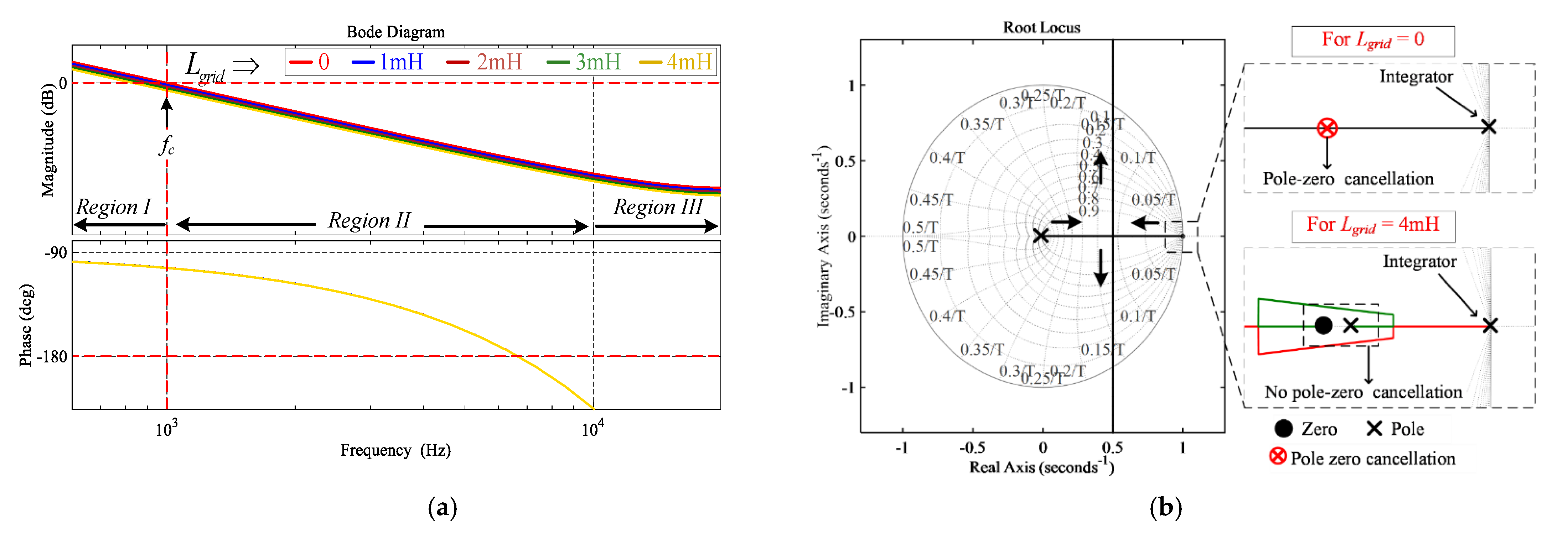
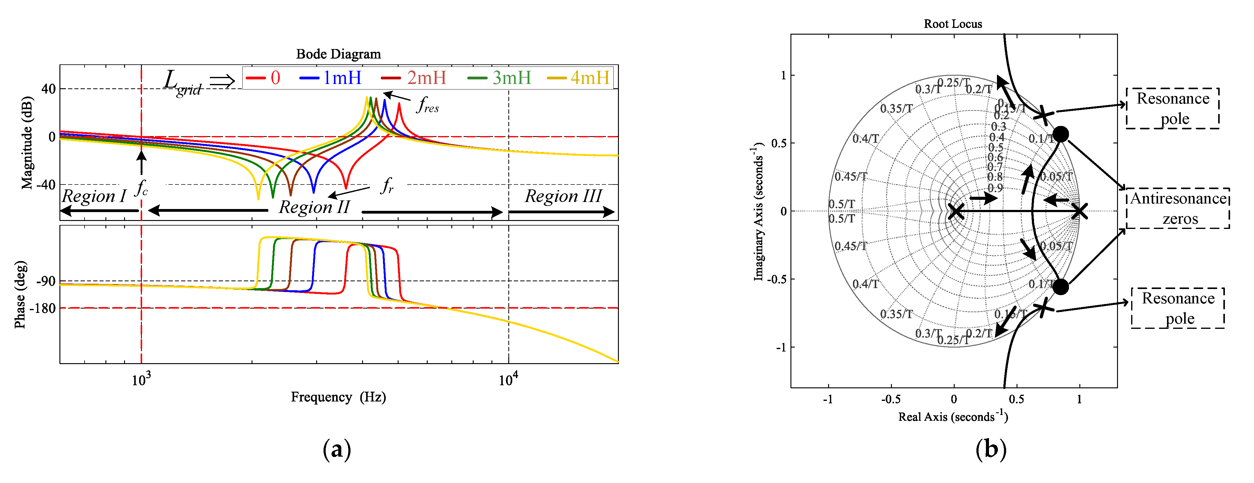
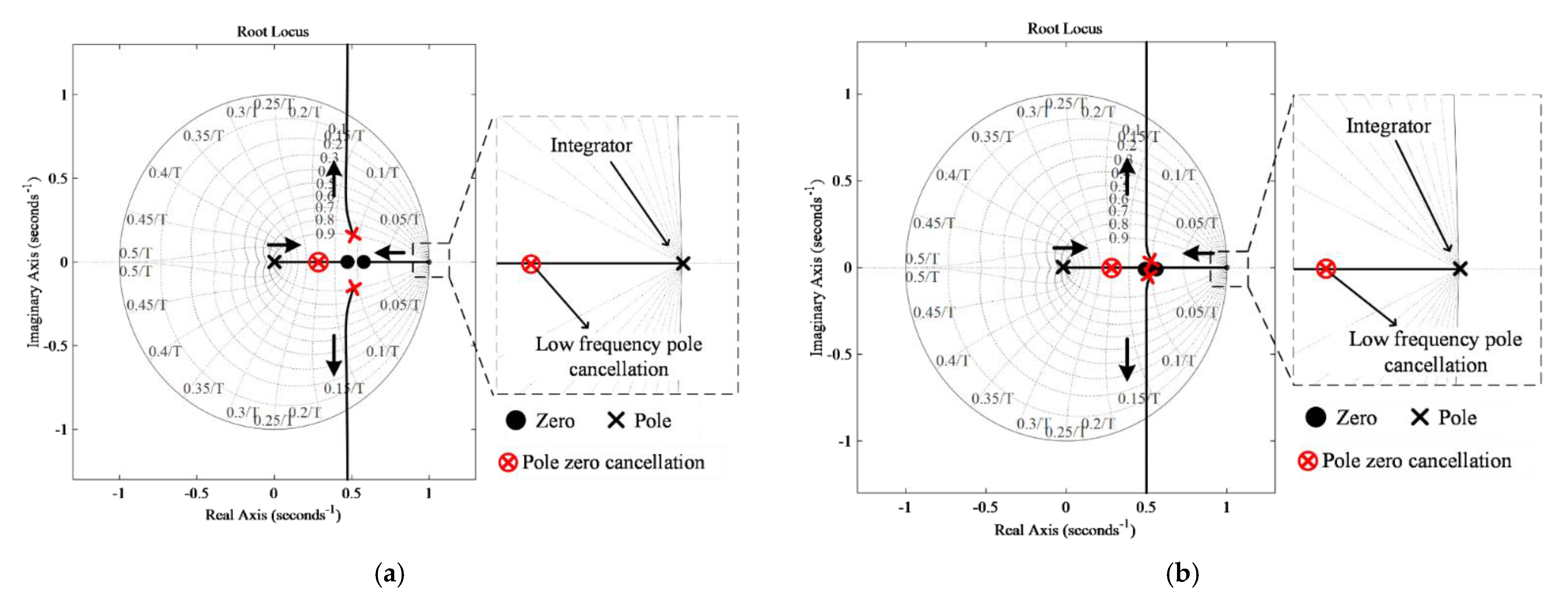
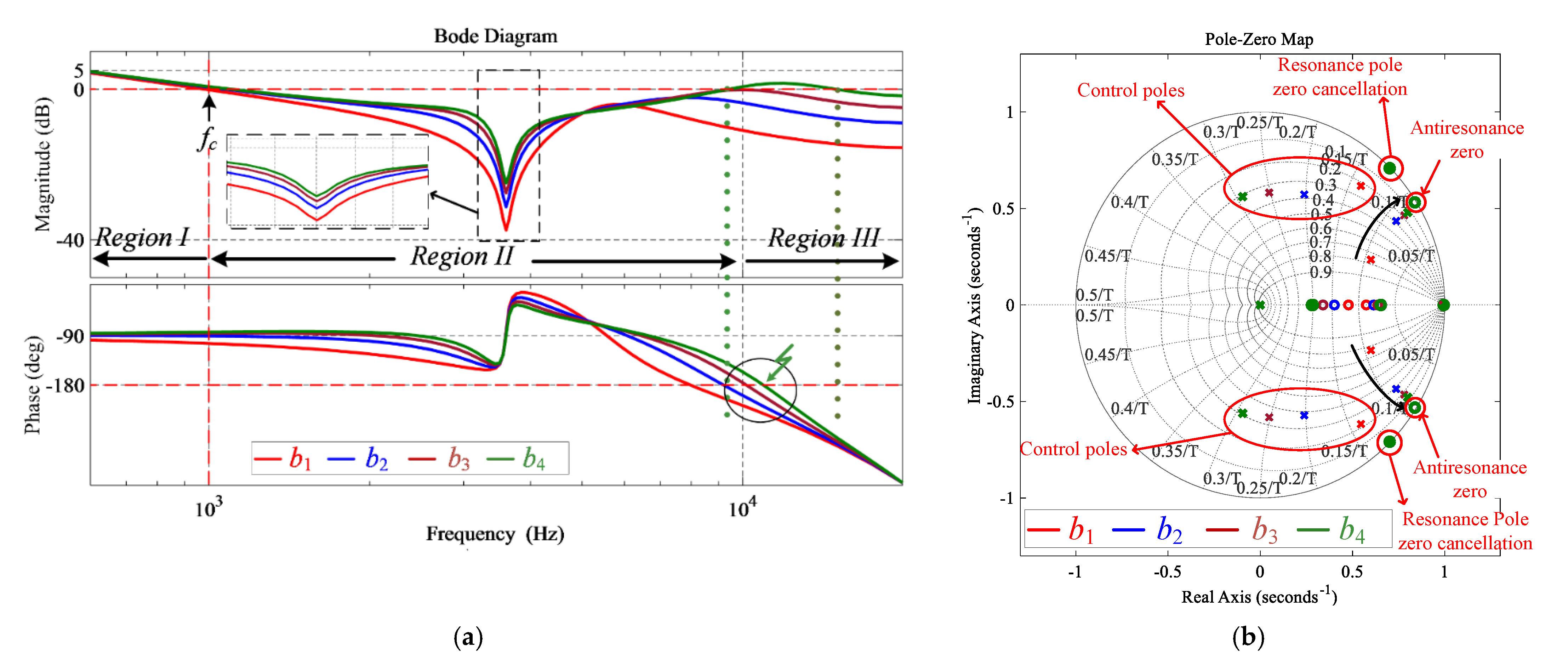
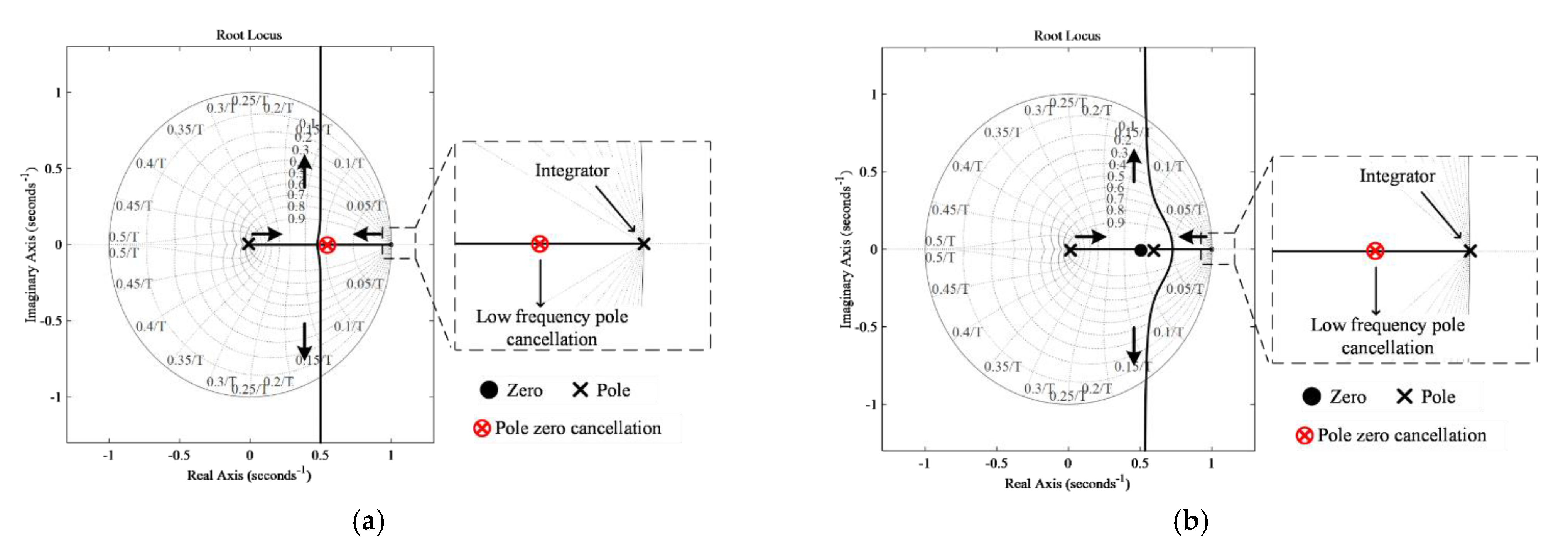
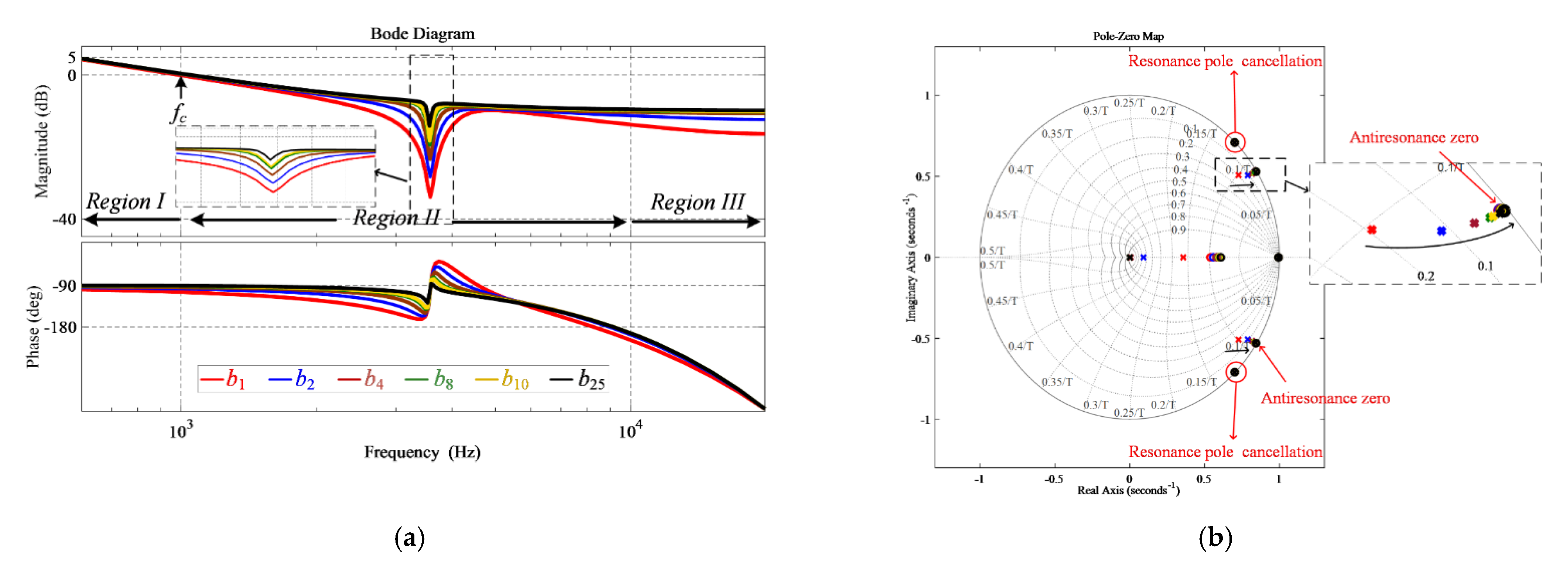
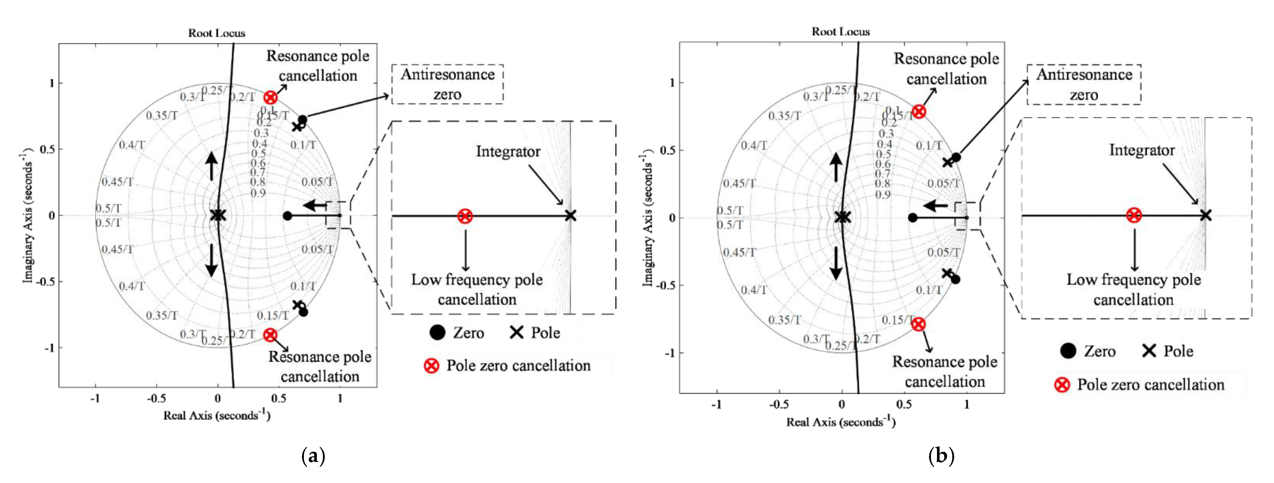
- The resonance poles in the LCL filter are effectively cancelled out with the pole-zero cancellation technique. In addition, the effect of antiresonance is greatly reduced by applying a pole near antiresonance zero.
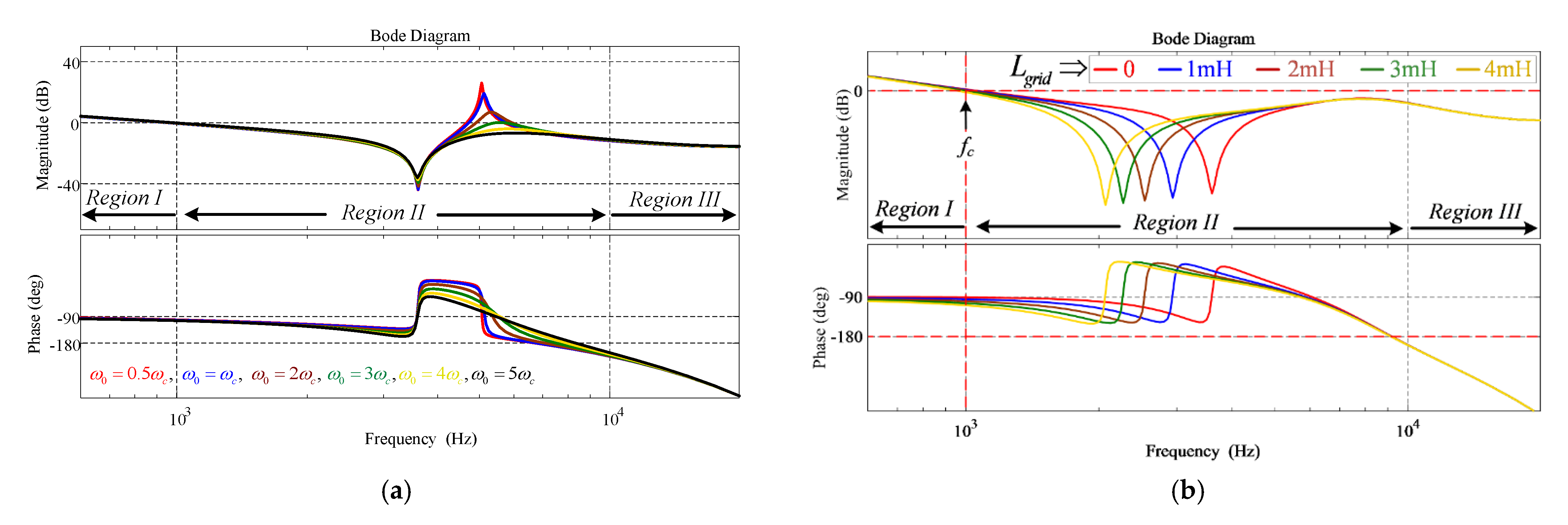
- The control parameters contributing to antiresonance peak reduction are discussed in detail in this paper.
- The resonance poles and antiresonance zeros cancellation can enhance the stability of the controller and overcome the bandwidth limitations.
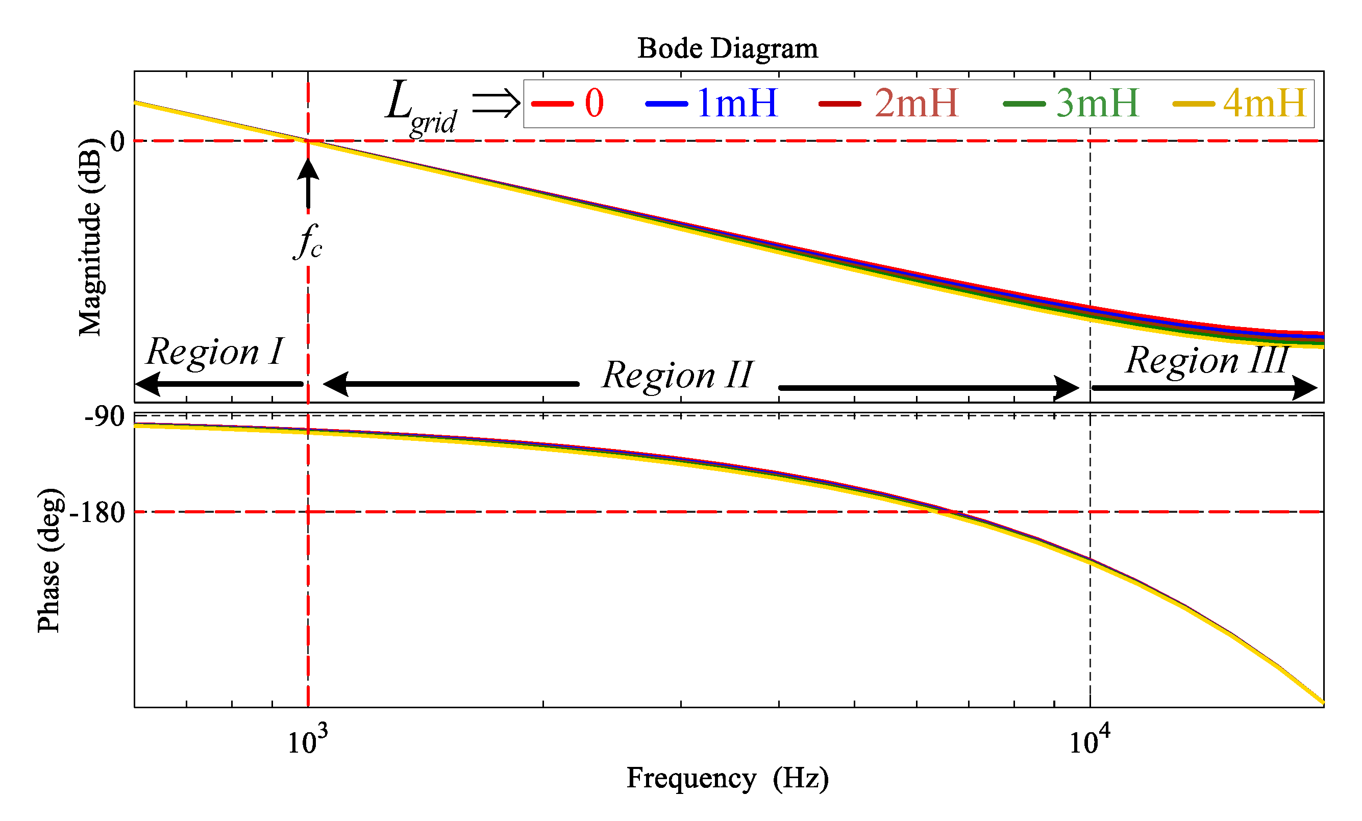
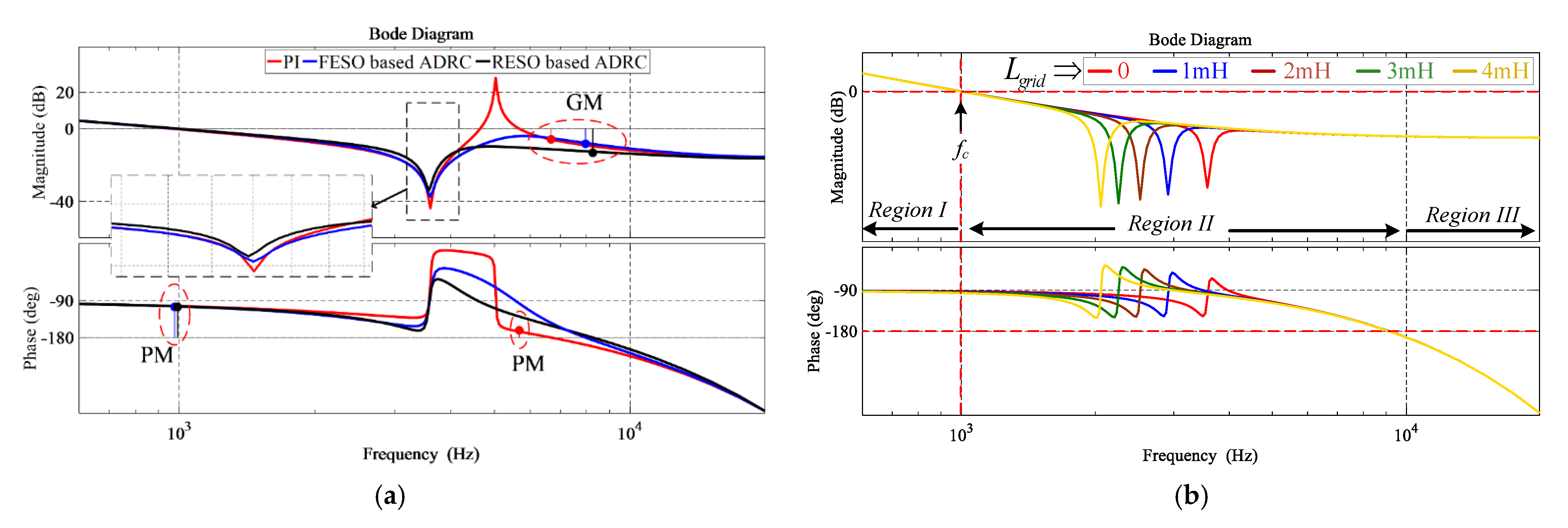
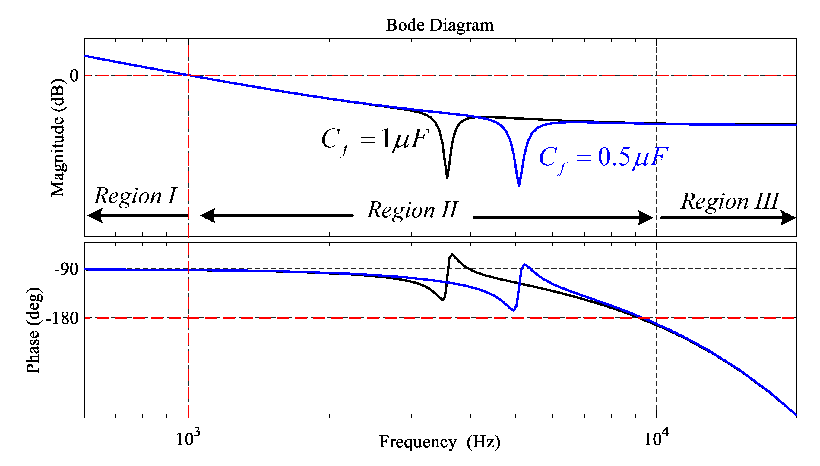
- The effectiveness of the pole-zero cancellation technique of the proposed controller is analyzed by frequency response analysis using Bode plots under different LCL filter design and grid impedance variations.
- The model-independent characteristics of the proposed control are explained from the robust performance of the control with either L or LCL filters under grid impedance uncertainty.
- The robustness of the proposed controller is related with the conventional single-loop PI control via simulation and only RESO based ADRC is compared with the conventional control via experimental results under different configurations of the plant.
The mathematical model and frequency response analysis of the GcI with L and LCL filters are addressed in Section 2. The single-loop PI control design and its stability is analyzed in Section 3. In Section 4, the proposed control expression and stability analysis are presented. The experimental verification to prove the analysis achieved in preceding sections is shown in Section 5, and concluding remarks are drawn in Section 6.
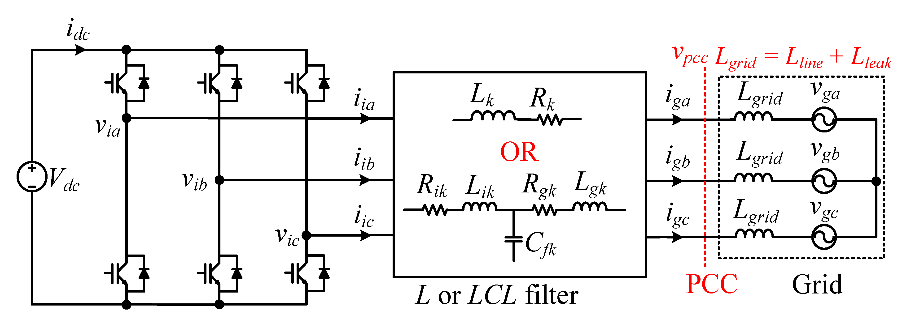
2. Mathematical Modeling of the System and Frequency Response Analysis
The three-phase GcI system, with either the L filter or the LCL filter, is shown in Figure 1 where the inverter is provided with the constant DC voltage . The voltage vpcc at the PCC is sensed to synchronize the current and grid voltage with the phase-locked loop. The grid impedance is mainly inductive, represented by , which may include the line inductance of high-voltage transmission line and leakage inductance of the power transformers. The grid voltage, inverter side voltage, grid side current, and inverter side current are denoted by , , , and , respectively, with used as an index for three phases , , and . In this section, the mathematical model of the L and LCL filter is presented and, afterward, their frequency response characteristics are analyzed with the grid impedance variation.
Figure 1.
Three-phase GcI with L or LCL filter.
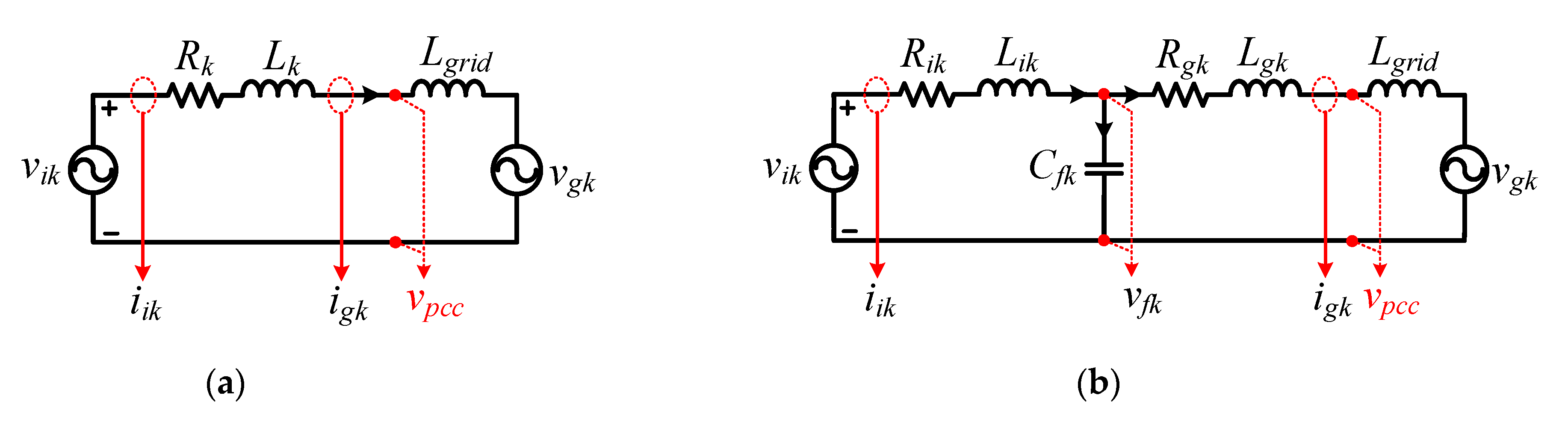
2.1. Mathematical Model of L Filter Type GcI
The equivalent single-phase circuit diagram for the L filter type GcI is shown in Figure 2a. The inductor and equivalent resistor are the parameters of the L filter. It is worth noting that sensing either the grid side current or inverter side current results in the same mathematical model [8].
Figure 2.
Equivalent single-phase circuits of GcI (a) With L filter; (b) With LCL filter.
The transfer function relating to for the L filter type GcI, in consonance with Figure 2a, can be expressed as
2.2. Mathematical Model of LCL Filter Type GcI
The equivalent single-phase circuit for the LCL filter type GcI is shown in Figure 2b. The grid side inductor , inverter inductor , with their equivalent resistors and , and the filter capacitor (where is the voltage across ) are the parameters of the LCL filter.
To achieve switch protection, inherent damping features, and operation under high grid impedance, the current is chosen for the system modeling and controller design in this paper [10,22]. The transfer function relating to , in accordance with Figure 2b, after ignoring the resistances and , can be expressed as
where and representing the filter resonance and antiresonance frequencies, respectively, are computed as
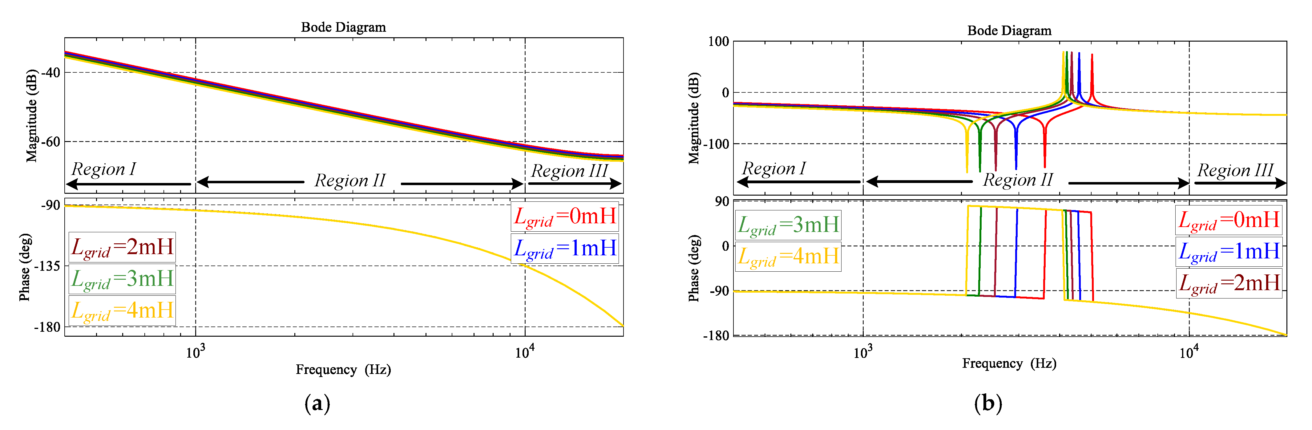
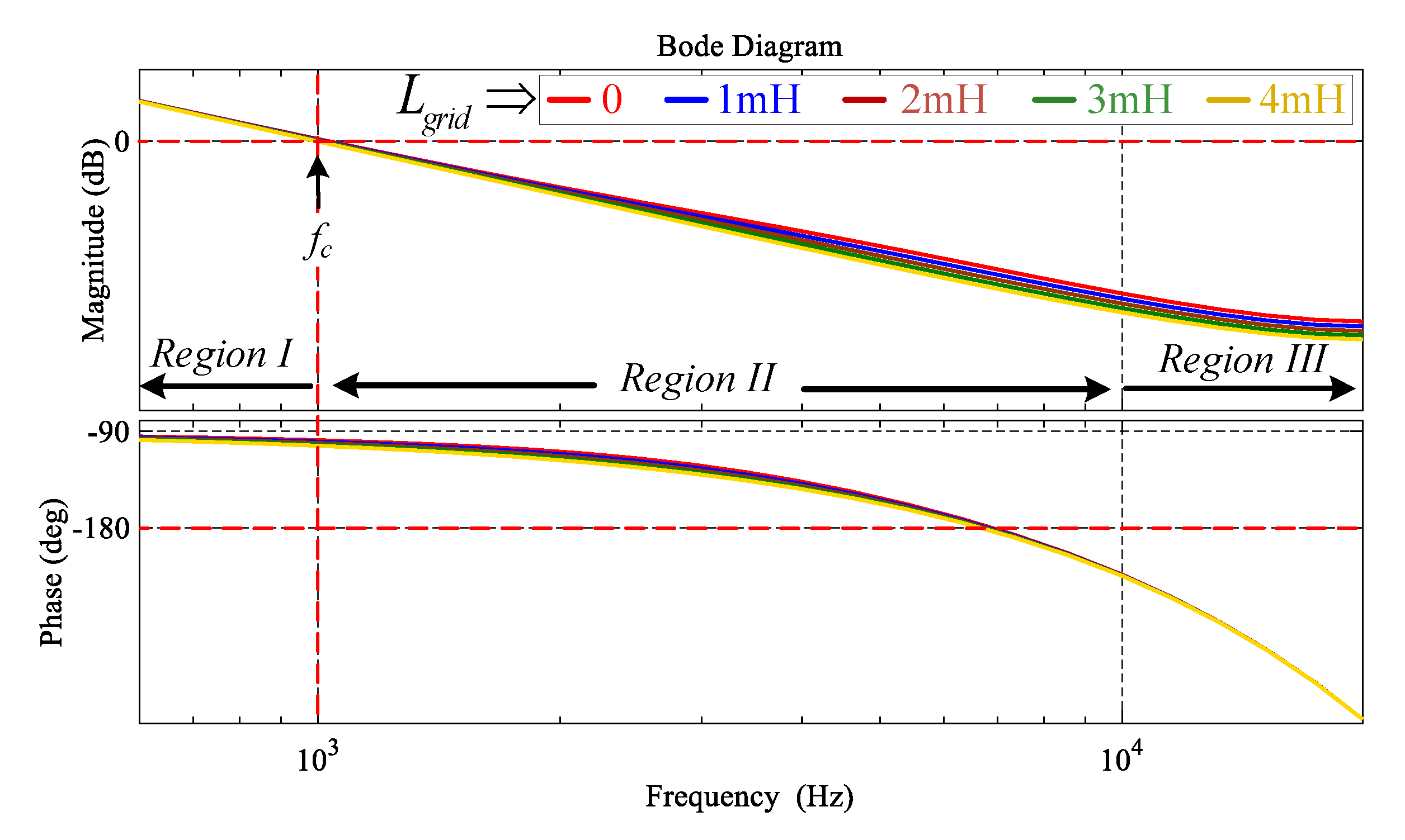
2.3. Frequency Response Analysis
The frequency response characteristics are divided into three different frequency regions. Region I is defined as a low frequency region, where the range covers the control bandwidth. Region II is termed as a resonance region, and Region III is a high frequency region where the range covers the switching and sampling frequencies. The frequency response characteristics of the L and LCL filter are analyzed individually under the grid impedance variations using the Bode plots, as shown in Figure 3a,b, using system parameters defined in Table 1. The characteristic frequency response for the L filter type GcI does not vary in all three regions of the frequencies, even under variations as shown in Figure 3a. With the LCL filter, the high frequency resonance poles and antiresonance zeros, located in Region II, create positive and negative peaks in the frequency response characteristics as shown in Figure 3b. This, in turn, makes the LCL filter characteristics different from those of the L filter in Region II. As the increases, the resonance and antiresonance effect may deteriorate and challenge the stable LCL filter design.
Figure 3.
Frequency response characteristics of the system under variations (a) L filter type GcI; (b) LCL filter type GcI.
Table 1.
System parameters.
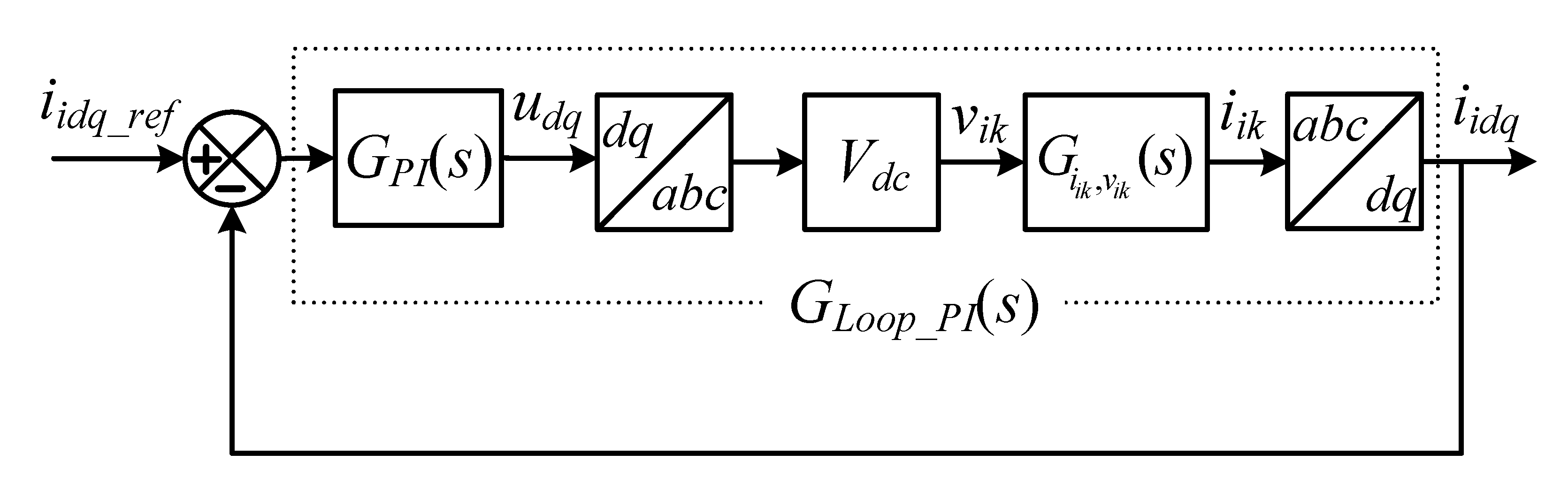
3. Conventional Single-Loop PI Current Control Modeling and Analysis
3.1. Control Modeling
The block diagram of the single-loop PI current control is shown in Figure 4. The inverter side current after the abc→dq transformation is chosen as the system variable for the control. The reference currents and are driven by active and reactive power references, respectively. The control dynamics, expressed by , are given as
where, the proportional gain and integral gain are derived as
and is the control bandwidth selected based on the desired controller performance.
Figure 4.
Block diagram of single-loop PI control for L or LCL filter type GcI.
Due to the single-loop control structure for the LCL filter, the dynamics associated with and are completely ignored in the stability and performance analysis [22]. The coupling effect in the inverter side current and grid voltage disturbances are compensated by the feedforward technique in the control signal [22]. However, it is not possible to achieve a perfect decoupled system due to the presence of delay in the loop [8]. Additionally, the grid voltage disturbance rejection with the feedforward technique depends on the filter type [9]. Consequently, in the stability analysis, decoupling and grid voltage disturbance rejection are also discarded. Besides, to avoid integrator saturation in the PI controller, an anti-windup mechanism can be adopted for each d and q current controllers.
Due to the discrete nature of the control algorithm, the computational and processing delay is also considered in the loop gain (not shown in Figure 4), equal to one sample period delay. The loop gain transfer function, , with the single-loop PI control for the L and LCL filter, using ZOH for discretization, (from Figure 5) is computed as [27]
3.2. Frequency Response Analysis
The frequency response characteristics of the single-loop PI control with the L and LCL filter type GcI are analyzed by Bode plot and root locus. The impact of grid impedance change on the magnitude and phase of the loop gain transfer function is investigated thoroughly. The similar frequency response characteristics of the L filter type GcI can be observed in all three regions of frequencies, as shown in Figure 5a, under grid impedance variation. The low frequency pole of L filter type GcI is cancelled by zero in the Region I as shown in Figure 5b. This pole-zero cancellation is affected with the change in as shown in Figure 5b. However, its impact on stability is negligible due to pole frequency being lower than the bandwidth of the control. The stability margins achieved with the single-loop PI control are provided in Table 2.
Figure 5.
Frequency response of Loop gain for L filter type GcI with single-loop PI control under variation (a) Using Bode Plots; (b) Root Loci.
Table 2.
Stability Analysis of Single-loop PI Control for the L Filter Type GcI.
The loop gain frequency response characteristics of the LCL filter type GcI in Region II remain affected by the resonance and antiresonance peaks with the single-loop PI control structure, as shown in Figure 6a. When is considered in the loop, the change in the resonance and antiresonance magnitude and frequency in Region II can be observed. In addition, the effective control bandwidth is reduced with an increase in because of the antiresonance peak approaching the selected 1 kHz bandwidth, as shown in Figure 6a and Table 3. This may cause a slower reference tracking and poor disturbance rejection capability [4,8].
Figure 6.
Loop gain Bode plots for the LCL filter type GcI with single-loop PI control under variation (a) Using Bode Plots; (b) Using Root loci.
Table 3.
Stability analysis of single-loop PI control for the LCL filter type GcI.
The Nyquist stability criterion reveals that the stability of the LCL filter type GcI in Region II of Figure 6a, due to the close vicinity of −180° phase crossing, changes with an increase in the grid impedance as shown in Table 3. The slight increase in the PM can be achieved at a low resonance frequency with high grid impedance, as shown in Table 3. Additionally, resonance poles remain near the boundary of the unit circle, which reflects lower stability margins, as shown in Figure 6b.
For system dynamics compensation, preserving the bandwidth, and robust stability of the controller, it is necessary to cancel out not only resonance poles but also antiresonance zeros present in the frequency response of the LCL filter type GcI. In addition, with the LCL filter, the simple proportional feedforward technique for the decoupling and grid voltage disturbance may not work effectively with the single-loop PI control [8]. For this reason, different controller structures with PI are advised along with an appropriately designed LCL filter, and the prior information about the grid impedance is required [28].
4. Current Control with the Proposed Linear ADRC
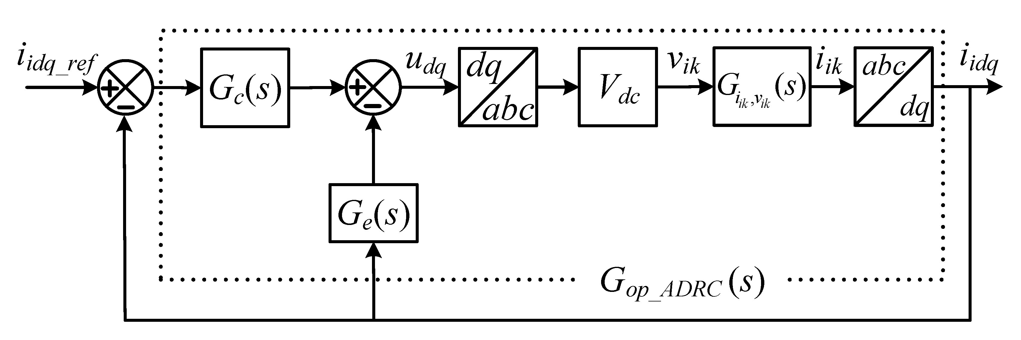
4.1. Control Modeling
The commonly used block diagram of the first-order linear ADRC is shown in Figure 7 where the only required information is the order of the system and the controller gain parameter . To proceed with the first-order ADRC, the L filter type GcI transfer function, derived in (3), is adopted for the control design. Subsequently, a similar control configuration without order modification is applied to the LCL filter type GcI to show the simplicity of the design. The transfer function of the L filter type GcI can be rewritten to match with the general structure of the linear ADRC as
where and . In the time domain, (7) can be transformed to
Figure 7.
General block diagram of the first-order linear ADRC, adapted with permission from [22], Copyright 2021 Elsevier.
This can generally be represented by
where the gain parameter , the only difference with the proposed control structures for the L and LCL filter type GcI, is initially opted as
and the system states and are computed from (11) and (12) as
where represents a generalized disturbance function, which describes the system variable to the control by , and disturbances and system uncertainties by . Based on (9) and (11), the state space model with the extended state can be represented as
and
The second-order ESO used to estimate and tracking and , respectively, is constructed as [24]
where the observer gains are selected as , and represent the observer bandwidth [23]. Note that , which is the only tuning parameter of ESO, determines the convergence rate of the ESO, selected as four times of in this paper [22].
The estimated state can be compensated by the controller, shown in Figure 7, as
here, is the output of the controller. By substituting (15) into (9), the original system can be approximated as
Note that, by applying the first-order ADRC, the system is approximated as a simple integrator without any dynamic uncertainty, as shown in (16). Therefore, simple proportional control can be employed as
where is the reference and and is the control bandwidth. With some straightforward deductions from (14), the estimated extended state of FESO, after taking Laplace transform, can be derived as
The construction of the linear ESO, as shown in (14), represents FESO. However, to estimate generalized disturbance function h only, the order of the ESO can be reduced as the system state is directly available for measurement. The RESO can be constructed with to track as [23]
By applying the Laplace transform, (19) is converted to
Then, by substituting (17) and (18) for FESO-based ADRC into (15), the control signal is derived as
Similarly, substituting (17) and (20), for RESO based ADRC, into (15), results in
The block diagram of the current controller for either FESO- or RESO-based ADRC, based on (21) and (22) with equal to , for the L or LCL filter type GcI, is shown in Figure 8 where and can be obtained from the first and second terms on the right side of (21) and (22) for the FESO- and RESO-based ADRC, respectively, as
Figure 8.
Block diagram of the current control of an L or LCL filter type GcI with either FESO- or RESO-based linear ADRC.
The input to the system instead of , as in Figure 8, is obtained by
The block diagram, shown in Figure 8, contains the inner and outer loop with FESO and RESO dynamics. The differences in Figure 7 and Figure 8 are the feedback signal replaced by instead of after the abc→dq transformation, and reference r by . The coupling effect and the grid voltage variation due to the uncertainty in are considered as disturbances estimated by FESO or RESO and compensated in the control law of the linear ADRC.
The loop gain transfer function for the L filter type GcI or LCL filter type GcI with FESO- and RESO-based ADRC with the consideration of one sampling delay for the computation, based on Figure 8 using ZOH for discretization, can be derived as
The stability of the proposed controller structures with FESO- and RESO-based ADRC for the L and LCL filter type GcI is analyzed separately. In addition, the control parameters’ impact on the proposed controller performance and robustness is discussed in detail.
4.2. Stability Analysis with FESO-Based ADRC
4.2.1. For L Filter Type GcI
The frequency response characteristics of the L filter type GcI remain the same in all three regions of frequencies, as shown in loop gain Bode plots in Figure 9, even under grid impedance change. The frequency response characteristics of the L filter type GcI with FESO-based ADRC matches with the single-loop PI control dynamics. However, with FESO-based ADRC, the control bandwidth is preserved, as shown in Table 4, and the feedforward technique for the decoupling, and grid voltage disturbance are not required. The grid voltage disturbances and coupling effect are being treated as disturbances in the generalized disturbance function and estimated by FESO. In addition, with changes in the grid impedance, a low frequency pole cancellation is not affected, which makes the FESO-based ADRC robust to the parameter uncertainty as shown in Figure 10.
Figure 9.
Loop gain Bode plots for L filter type GcI with FESO-based ADRC under variation.
Table 4.
Stability Analysis of FESO-Based ADRC for the L Filter Type GcI.
Figure 10.
Pole-zero map of loop gain transfer function for L filter type GcI with FESO-based ADRC (a) For Lgrid = 0; (b) Lgrid = 4 mH.
4.2.2. For LCL Filter Type GcI
The frequency response characteristics of the loop gain transfer function are analyzed using Bode plots and pole-zero map with FESO-based ADRC for the LCL filter type GcI. First, the characteristics of loop gain are compared with the variation in the gain parameter b to reduce the modification in the proposed control structures for the L and LCL filter type GcI, as shown in Figure 11. It is clear that FESO-based ADRC can successfully compensate the resonance effect with the pole-zero cancellation technique. In addition, the presence of an antiresonance peak can also be reduced with a decrease in b, as shown in Figure 11a, until two proposed control structures for the L and LCL filter type GcI match, where bm can be derived as
with b derived from (8) and (9) for the LCL filter type GcI. With the decrease in b, the ADRC introduces a pole near the antiresonance zero as indicated in Figure 11b. The two proposed control structures for the L and LCL filter type GcI become identical with the adoption of b as b5. However, the variation in b has some limitations with the FESO-based control structure as shown in Figure 11a in the Region III. The control structure becomes marginally stable with the adoption of b as b3 and unstable as b4 according to the Nyquist stability criterion. This limitation arises from the control poles introduced by FESO-based ADRC, as shown in Figure 11b, whose locus may go out of the unit circle with a decrease in b. With a decrease in the gain parameter b, a slight increase in the bandwidth is also observed as indicated in Figure 11a; however, this can be ignored here.
Figure 11.
Loop gain frequency response using FESO-based ADRC for LCL filter type GcI under variation in gain parameter b (a) Using Bode Plots; (b) Using root loci.
The observer bandwidth also plays an important role in the resonance and antiresonance peak reduction present in the frequency characteristics of the LCL filter, as shown in Figure 12a, with FESO-based ADRC. However, the observer bandwidth is limited by the measurement noise, and it is selected as in this paper [22].
Figure 12.
Loop gain Bode plots for LCL filter type GcI with FESO-based ADRC (a) Under observer bandwidth variation; (b) Under grid impedance variation.
The resonance effect in the LCL filter is effectively mitigated, as shown in Figure 12b, even under grid impedance change where the value of b is selected as b2. However, due to the antiresonance peak in the loop gain bode plot, the bandwidth of the control is limited as shown in Table 5. To preserve the bandwidth of the control, it is necessary to mitigate the antiresonance peak. For this reason, RESO-based ADRC control structure is employed in this paper.
Table 5.
Stability Analysis of FESO Based ADRC for the LCL Filter Type GcI.
4.3. Stability Analysis of RESO-Based ADRC
For L Filter Type GcI
The frequency response characteristics of the L filter type GcI does not change in all three regions of the frequency, as shown in Figure 13, with grid impedance variations. The control bandwidth is also preserved, which creates the performance of the control-like FESO-based ADRC with the L filter type GcI, as illustrated in Table 6. However, the simple control design is achieved by adopting RESO with the ADRC. The low frequency pole of the L filter type GcI is cancelled by the pole-zero cancellation technique, in the same way as FESO-based ADRC, even under grid impedance change, as shown in Figure 14a,b, without control tuning.
Figure 13.
Loop gain frequency response characteristics of the L filter type GcI with RESO-based ADRC under grid impedance variation.
Table 6.
Stability Analysis of RESO Based ADRC for the L Filter Type GcI.
Figure 14.
Root locus of loop gain transfer function for L filter type GcI with RESO-based ADRC: (a) For Lgrid = 0; (b) For Lgrid = 4 mH.
The stability of RESO-based ADRC for the LCL filter type GcI is also analyzed with Bode plots and pole-zero maps against variations in gain parameter b as shown in Figure 15. It can be seen from Figure 15a that the magnitude of the antiresonance peak decreases with a decrease in b, which may create a similar controller configuration for the L and LCL filter type GcI with b adopted as b5. In addition, a further decrease in b is also possible with RESO-based ADRC as it does not make the controller unstable, unlike FESO-based ADRC. With the continuous decrease in b, the pole introduced by RESO-based ADRC comes near the antiresonance zero and pole-zero cancellation also takes place as shown in Figure 15b. In addition, the can be a very crucial factor with resonance and antiresonance peak reduction with RESO-based ADRC as with FESO-based ADRC.
Figure 15.
The frequency response of the loop gain using RESO-based ADRC for the LCL filter type GcI under variations in gain parameter b (a) Using Bode plot; (b) Using pole-zero map.
The loop gain frequency response characteristics of the LCL filter type GcI with conventional PI control, FESO- and RESO-based ADRC are compared in Figure 16a with Bode plots. The characteristics, shown for FESO- and RESO-based ADRC, are under the nominal value of b selected from (8) and (9). The resonance effect is completely compensated by FESO- and RESO-based ADRC and the antiresonance peak is greatly reduced in comparison with conventional PI control. Due to the higher damping ratio, the antiresonance peak can be reduced further when RESO-based ADRC control configuration is chosen as shown in Figure 16a. It is also clearly mentioned that the stability margins are significantly improved with the proposed ADRC in comparison with conventional PI control. Due to the simplicity of control design, more effective compensation of the resonance and antiresonance peak, high robustness, and the preserved bandwidth, the RESO-based ADRC is adopted for the control design in this paper.
Figure 16.
Loop gain frequency response characteristics (a) PI, FESO, and RESP-based ADRC comparison; (b) with the RESO-based ADRC under Lgrid variation.
Using (25), the frequency response characteristics of loop gain transfer function using RESO-based ADRC with Bode plots are shown in Figure 16b with variations in . The gain parameter b is selected as b5 to make it similar to the L filter type GcI. The resonance poles in the Region II of the LCL filter type GcI are perfectly damped by RESO-based ADRC by using pole-zero cancellation, as shown Figure 16b and Figure 17, even under grid impedance variations. However, a small variation is observed in Region II, as shown in Figure 16b, because the antiresonance peak compensation depends on , , , and gain parameter . Fortunately, this variation can be ignored as it does not affect the bandwidth or stability of the proposed controller. The performance and robustness of the proposed controller is preserved, even under the grid impedance variation, as shown in Table 7. In addition, the stability of the proposed control is sus tained with an increase in the resonance frequency, by decreasing the filter capacitance of the LCL filter type GcI beyond the limits of the conventional single-loop PI control i.e., as shown in Figure 18 [22].
Figure 17.
Root locus of loop gain transfer function for the LCL filter type GcI with RESO-based ADRC (a) For Lgrid = 0; (b) For Lgrid = 4 mH.
Table 7.
Stability Analysis with the Proposed RESO Based ADRC for the LCL Filter Type GcI.
Figure 18.
Loop gain Bode plots under different filter capacitance of the LCL filter type GcI.
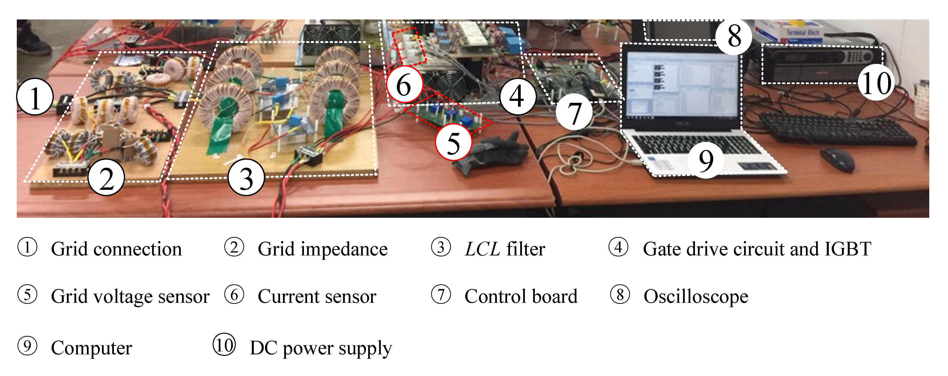
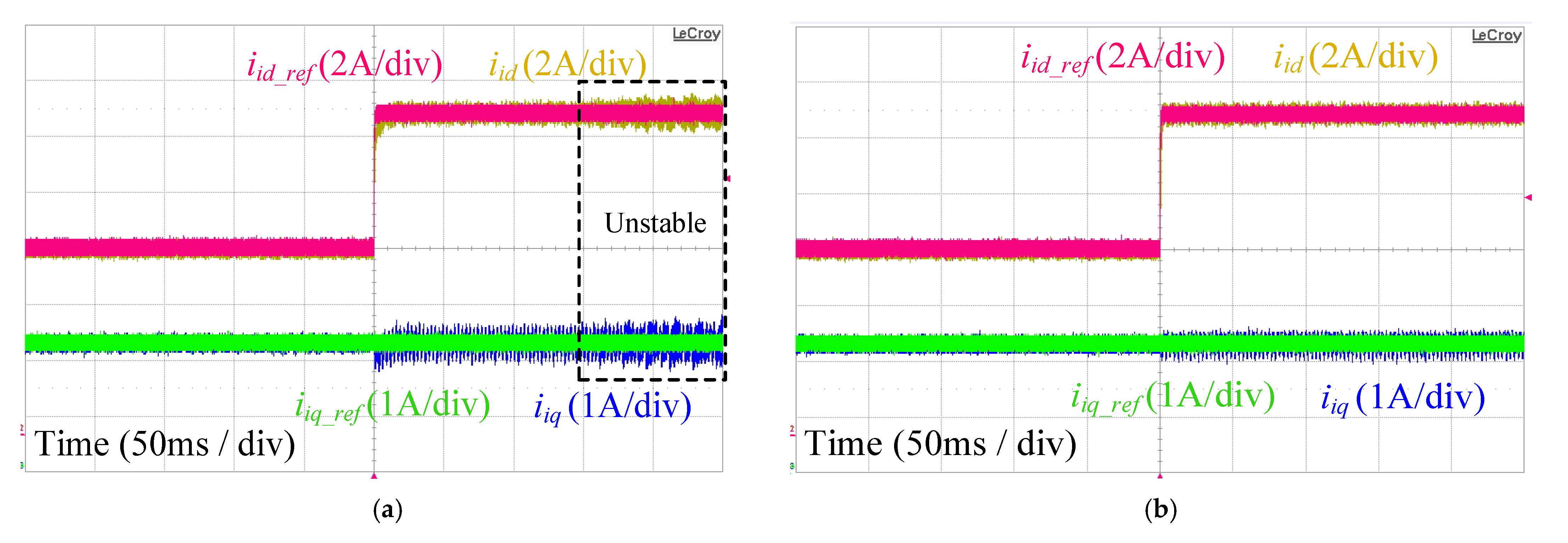
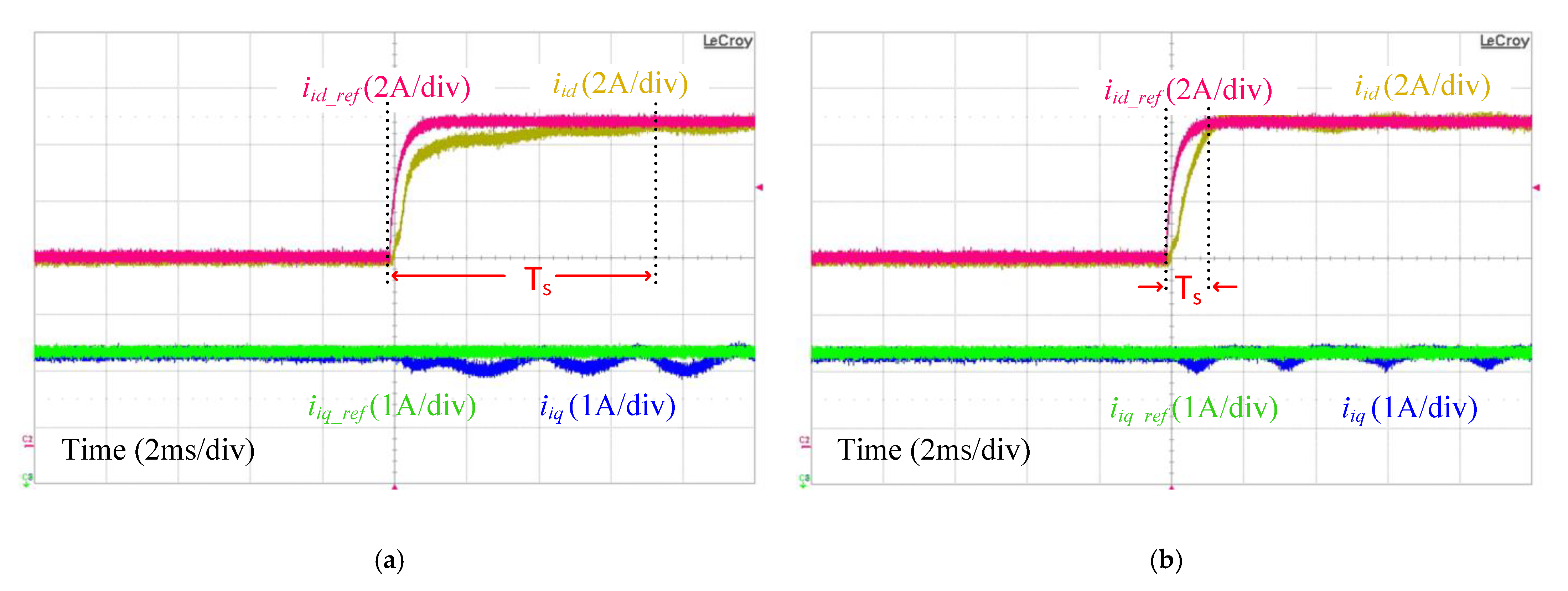
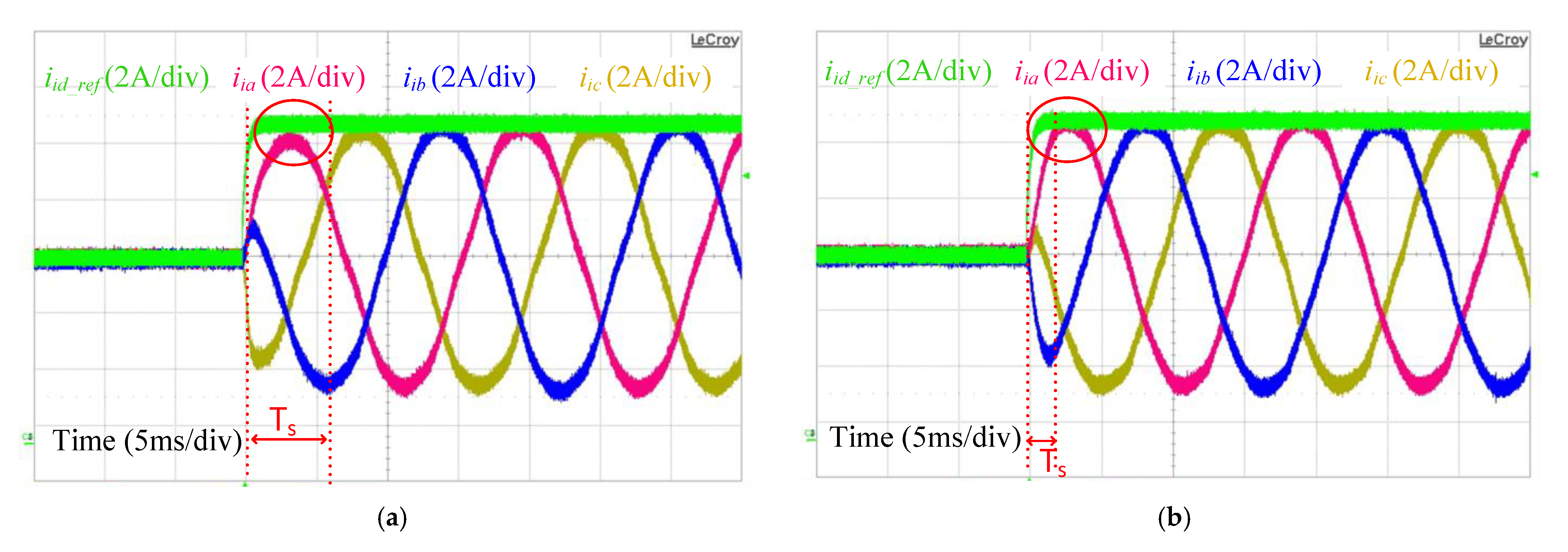
5. Experimental Results
The series of experiments were performed on a three-phase GcI system with either L or LCL filter. To introduce inductance into the grid, an additional inductor was added in series with the grid side inductor . Additionally, a three-phase transformer was used to isolate the inverter from the grid, and the leakage inductance of the transformer was also included in . The complete experimental setup is shown in Figure 19.
Figure 19.
Experimental setup of the three-phase LCL filter type GcI under grid impedance, reprinted with permission from [22] Copyright 2021 Elsevier.
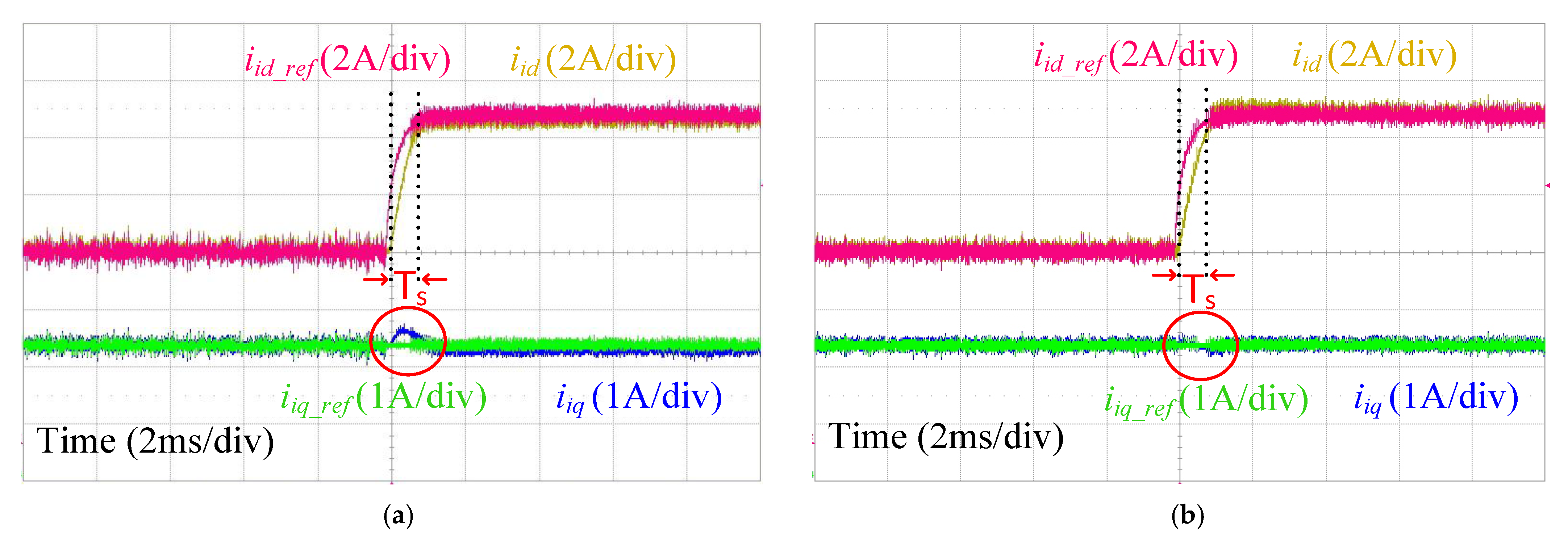
5.1. Performance Comparison with the L Filter Type GcI
By setting the bandwidth as 1 kHz with the L filter type GcI, the settling time with the conventional single-loop PI control and proposed RESO-based ADRC due to the assumption of the system as a simple integrator was found to be approximately 900 µs [26]. From the reference tracking of and components of the inverter side current , shown in Figure 20, it was verified that the proposed and conventional control method followed the calculated and achieved the selected bandwidth for the control. However, due to the existence of the coupling between and , the proposed control seemed to have better decoupling characteristics than its counterpart single-loop PI control. The impact of the grid impedance variations on the performance of the proposed and conventional single-loop PI control with the L filter type GcI was negligible; hence, only one waveform is shown in this paper with zero .
Figure 20.
Current tracking and for L filter type GcI with (a) single-loop PI control; (b) RESO-based ADRC.
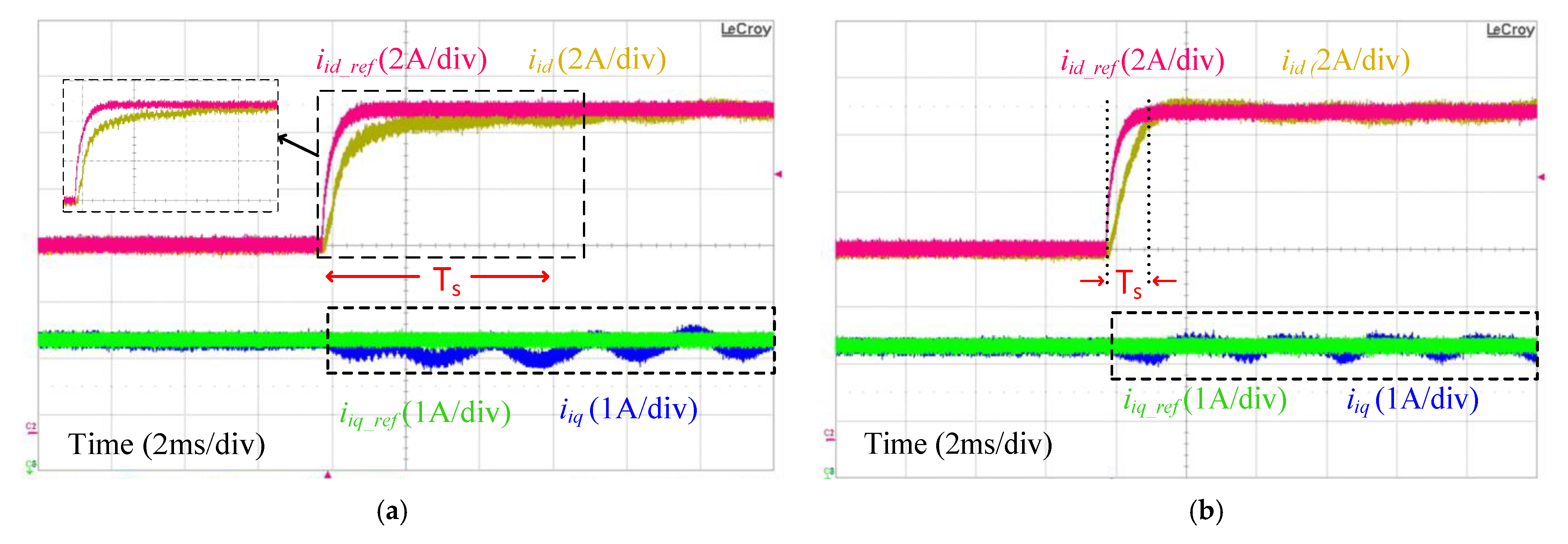
5.2. Performance Comparison with the LCL Filter Type GcI
The current tracking results of and components of the inverter side current with the LCL filter type GcI are shown in Figure 21 with zero grid impedance for the proposed and conventional single-loop PI control. The proposed RESO-based ADRC can produce the required , whereas the slower control dynamics are observed with the single-loop PI control in the case of the LCL filter. The different filter configurations have no impact on the proposed RESO-based ADRC control performance, which proves the model-independent characteristics of the control. Furthermore, oscillations in the transient state clearly explain the resonance effect present in the single-loop PI control structure, which may grow further if the parasitic resistance and of the LCL filter are lowered. In comparison, the linear ADRC not only compensates the resonance and antiresonance effects present in the LCL filter but also achieves better decoupled control.
Figure 21.
Current tracking of and with (a) single-loop PI control; (b) RESO-based ADRC.
Due to effective dynamic compensation with the proposed method, it is also possible to increase the resonance frequency by lowering filter capacitance or filter inductances and . The effect of an increase in the resonance frequency, by adopting , on the performance of the proposed and single-loop PI control can be seen in Figure 22, where the single-loop PI control becomes unstable, however RESO-based ADRC maintains its stability. The performance comparison of the proposed and conventional single-loop PI control, with , can also be verified from the three-phase inverter side current as shown in Figure 23.
Figure 22.
Current tracking of and with (a) Single-loop PI control; (b) RESO-based ADRC.
Figure 23.
Three-phase inverter side current with (a) Single-loop PI control; (b) RESO-based ADRC.
The controller performance, under , can be seen in Figure 24 for the single-loop PI control and the proposed RESO-based ADRC. The oscillations in single-loop PI control are reduced somehow due to increases in the stability margin with an increase in the grid impedance . However, the controller dynamics are affected with an increase in the due to the closeness of the controller bandwidth and the antiresonance peak as described in Section 3. In contrast, similar control dynamics are achieved, even under high grid impedance, with the proposed method without any controller modification or tuning. Furthermore, the model-independent characteristics can also be verified from the tracking response, which remains the same under grid impedance uncertainty.
Figure 24.
Current tracking of and with (a) Single-loop PI control; (b) RESO based-ADRC.
The performance of the proposed RESO-based ADRC, based on its bandwidth preservation, can also be verified from the settling time from the three-phase inverter side current along with its d-component current reference, with (Figure 25).
Figure 25.
Three-phase inverter side current with (a) Single-loop PI control; (b) RESO-based ADRC.
6. Conclusions
The resonance and antiresonance peaks present in the LCL filter type GcI with the inverter side current are effectively damped with the RESO-based ADRC using the pole-zero cancellation technique, without any prior information about the plant. Increased robustness of the controller, along with faster dynamics (even under grid impedance uncertainty or different filter configuration) were demonstrated with a frequency response method and verified experimentally. The simplicity of the proposed control design is explained based on the adoption of the similar control design for both the L and LCL filter type GcIs plants.
Author Contributions
Conceptualization, M.S. and R.-Y.K.; methodology, M.S., R.-Y.K.; software, M.S.; validation, M.S. and R.-Y.K.; formal analysis, M.S. and H.T.; investigation, M.S., R.-Y.K. and H.T.; resources, R.-Y.K.; data curation, M.S., M.H.A.K.K.; writing—original draft preparation, M.S., M.H.A.K.K., H.T. and R.-Y.K.; writing—review and editing, M.S. and M.H.A.K.K. visualization, M.S. and H.T.; supervision, R.-Y.K.; project administration, H.T.; funding acquisition, M.S. All authors have read and agreed to the published version of the manuscript.
Funding
This research received no external funding.
Institutional Review Board Statement
Not applicable.
Informed Consent Statement
Not applicable.
Conflicts of Interest
The authors declare no conflict of interest.
References
- Blaabjerg, F. Control of Power Electronics Converters and Systems, 1st ed.; Academic Press: Cambridge, MA, USA, 2018. [Google Scholar]
- Tang, W.; Ma, K.; Song, Y. Critical Damping Ratio to Ensure Design Efficiency and Stability of LCL Filters. IEEE Trans. Power Electron. 2020, 36, 315–325. [Google Scholar] [CrossRef]
- Dannehl, J.; Fuchs, F.W.; Hansen, S.; Thøgersen, P.B. Investigation of active damping approaches for PI based current control of a grid-connected pulse width modulation converters with LCL filters. IEEE Trans. Ind. Appl. 2010, 46, 1509–1517. [Google Scholar] [CrossRef]
- Dannehl, J.; Liserre, M.; Fuchs, F.W. Filter-based active damping of voltage source converters with LCL filter. IEEE Trans. Ind. Electron. 2011, 58, 3623–3633. [Google Scholar] [CrossRef]
- Yao, W.; Yang, Y.; Zhang, X.; Blaabjerg, F.; Loh, P.C. Design and analysis of robust active damping of LCL filters using digital notch filters. IEEE Trans. Power Electron. 2017, 32, 2360–2375. [Google Scholar] [CrossRef] [Green Version]
- Li, X.; Fang, J.; Tang, Y.; Wu, X.; Geng, Y. Capacitor-voltage feedforward with full delay compensation to improve weak grids adaptability of LCL-filtered grid-connected converters for distribution generation systems. IEEE Trans. Power Electron. 2018, 33, 749–764. [Google Scholar] [CrossRef]
- Bierhoff, M.; Soliman, R. Analysis and Design of Grid-Tied Inverter with LCL Filter. IEEE Open J. Power Electron. 2020, 1, 161–169. [Google Scholar] [CrossRef]
- Wang, J.; Yan, J.; Jiang, L.; Zou, J. Delay-dependent stability of single-loop controlled grid-connected inverters with LCL filters. IEEE Trans. Power Electron. 2016, 31, 743–757. [Google Scholar] [CrossRef] [Green Version]
- He, Y.; Wang, X.; Ruan, X.; Pan, D.; Qin, K. Hybrid Active Damping Combining Capacitor Current Feedback and Point of Common Coupling Voltage Feedforward for LCL-Type Grid-Connected Inverter. IEEE Trans. Power Electron. 2021, 36, 2373–2383. [Google Scholar] [CrossRef]
- Miskovic, V.; Klasko, V.; Jahns, T.M.; Smith, A.H.C.; Romenesko, C. Observer-based active damping of LCL resonance in grid-connected voltage source converters. IEEE Trans. Ind. Appl. 2014, 50, 3977–3985. [Google Scholar] [CrossRef]
- Sadabadi, M.S.; Haddadi, A.; Karimi, H.; Karimi, A. A robust active damping control strategy for LCL-based grid-connected DG unit. IEEE Trans. Ind. Electron. 2017, 64, 8055–8065. [Google Scholar] [CrossRef]
- Zhang, S.; Jiang, S.; Lu, X.; Ge, B.; Peng, F.Z. Resonance issues and damping techniques for grid-connected inverters with long transmission cable. IEEE Trans. Power Electron. 2014, 29, 110–120. [Google Scholar] [CrossRef]
- Kraemer, R.A.S.; Carati, E.G.; Cardoso, R.; da Costa, J.P.; Stein, C.M.O. Virtual State Damping for Resonance Suppression and Robustness Improvement in LCL-Type Distributed Generation Inverters. IEEE Trans. Energy Convers. 2021, 36, 1216–1225. [Google Scholar] [CrossRef]
- Awal, M.A.; della Flora, L.; Husain, I. Observer Based Generalized Active Damping for Voltage Source Converters with LCL Filters. IEEE Trans. Power Electron. 2021. [Google Scholar] [CrossRef]
- Liu, J.; Wu, W.; Chung, H.S.-H.; Blaabjerg, F. Disturbance Observer-Based Adaptive Current Control With Self-Learning Ability to Improve the Grid-Injected Current for $LCL$ -Filtered Grid-Connected Inverter. IEEE Access 2019, 7, 105376–105390. [Google Scholar] [CrossRef]
- Al-Durra, A.; Errouissi, R. Robust Feedback-Linearization Technique for Grid-Tied LCL Filter Systems Using Disturbance Estimation. IEEE Trans. Ind. Appl. 2019, 55, 3185–3197. [Google Scholar] [CrossRef]
- Su, M.; Cheng, B.; Sun, Y.; Tang, Z.; Guo, B.; Yang, Y.; Blaabjerg, F.; Wang, H. Single-Sensor Control of LCL-Filtered Grid-Connected Inverters. IEEE Access 2019, 7, 38481–38494. [Google Scholar] [CrossRef]
- Tran, T.V.; Kim, K. Frequency Adaptive Grid Voltage Sensorless Control of LCL-Filtered Inverter Based on Extended Model Observer. IEEE Trans. Ind. Electron. 2020, 67, 7560–7573. [Google Scholar] [CrossRef]
- Gao, N.; Lin, X.; Wu, W.; Blaabjerg, F. Grid Current Feedback Active Damping Control Based on Disturbance Observer for Battery Energy Storage Power Conversion System with LCL Filter. Energies 2021, 14, 1482. [Google Scholar] [CrossRef]
- Cao, Y.; Zhao, Q.; Ye, Y.; Xiong, Y. ADRC-Based Current Control for Grid-Tied Inverters: Design, Analysis, and Verification. IEEE Trans. Ind. Electron. 2020, 67, 8428–8437. [Google Scholar] [CrossRef]
- Chen, W.; Yang, J.; Guo, L.; Li, S. Disturbance-Observer-Based Control and Related Methods—An Overview. IEEE Trans. Ind. Electron. 2016, 63, 1083–1095. [Google Scholar] [CrossRef] [Green Version]
- Saleem, M.; Choi, K.-Y.; Kim, R.-Y. Resonance damping for an LCL filter type grid-connected inverter with active disturbance rejection control under grid impedance uncertainty. Int. J. Electr. Power Energy Syst. 2019, 109, 444–454. [Google Scholar] [CrossRef]
- Saleem, M.; Ko, B.-S.; Kim, S.-H.; Kim, S.-I.; Chowdhry, B.S.; Kim, R.-Y. Active Disturbance Rejection Control Scheme for Reducing Mutual Current and Harmonics in Multi-Parallel Grid-Connected Inverters. Energies 2019, 12, 4363. [Google Scholar] [CrossRef] [Green Version]
- Tran, T.V.; Kim, K.-H.; Lai, J.-S. Optimized Active Disturbance Rejection Control With Resonant Extended State Observer for Grid Voltage Sensorless LCL-Filtered Inverter. IEEE Trans. Power Electron. 2021, 36, 13317–13331. [Google Scholar] [CrossRef]
- Ma, W.; Guan, Y.; Zhang, B.; Wu, L. Active Disturbance Rejection Control Based Single Current Feedback Resonance Damping Strategy for LCL-Type Grid-Connected Inverter. IEEE Trans. Energy Convers. 2021, 36, 48–62. [Google Scholar] [CrossRef]
- Fu, C.; Tan, W. Parameters Tuning of Reduced-Order Active Disturbance Rejection Control. IEEE Access 2020, 8, 72528–72536. [Google Scholar] [CrossRef]
- Franklin, G.F.; Powell, J.D.; Workman, M.L. Digital Control of Dynamic Systems, 3rd ed.; Addison-Wesley: Reading, MA, USA, 1997. [Google Scholar]
- Dannehl, J.; Wessels, C.; Fuchs, F.W. Limitations of voltage-oriented PI current control of grid connected PWM rectifiers with LCL filters. IEEE Trans. Ind. Electron. 2008, 56, 380–388. [Google Scholar] [CrossRef]
Publisher’s Note: MDPI stays neutral with regard to jurisdictional claims in published maps and institutional affiliations. |
© 2021 by the authors. Licensee MDPI, Basel, Switzerland. This article is an open access article distributed under the terms and conditions of the Creative Commons Attribution (CC BY) license (https://creativecommons.org/licenses/by/4.0/).