Article

Study on Comprehensive Performance of Three-Dimensional Tube Applied to Gas–Solid Two-Phase Flow Environment

1
Guangzhou Institute of Energy Conversion, Chinese Academy of Sciences, Guangzhou 510640, China
2
Key Laboratory of Renewable Energy, Chinese Academy of Sciences, Guangzhou 510640, China
3
Guangdong Key Laboratory of New and Renewable Energy Research and Development, Guangzhou 510640, China
4
Institute of Building Energy and Thermal Science, Henan University of Science and Technology, Luoyang 471023, China
*
Author to whom correspondence should be addressed.
Energies 2021, 14(17), 5274; https://doi.org/10.3390/en14175274
Submission received: 13 July 2021 / Revised: 15 August 2021 / Accepted: 20 August 2021 / Published: 25 August 2021
(This article belongs to the Section J: Thermal Management)

Abstract

:
The three-dimensional tubular heat exchanger has excellent performance in single-phase flow, but its performance in gas solid two-phase flow is still lacking research. In this paper, analysis and comparison of heat exchanger prototypes made up of four different three-dimensional tubes by different comprehensive performance evaluation methods are carried out through experimental research and theoretical analysis. The research results show that the ratio of the long axis to the short axis of the three-dimensional tube has an important influence on its heat transfer performance and flow resistance. Furthermore, a reasonable ratio can be obtained by comparing its comprehensive performance. Among the comprehensive performance analysis results of four kinds of three-dimensional tubes, the comprehensive performance factor ηo-I of type I is the best which achieves the purpose of heat transfer enhancement. Results from the current research could provide beneficial guidance for further design and application of the three-dimensional tubular heat exchanger.

1. Introduction

The performance of an excellent heat exchanger should not only meet the process requirements, but also have good economic benefits. The performance of a heat exchanger is affected by its heat transfer performance, flow resistance, anti-wear and anti-scaling, among which the heat transfer performance and resistance characteristics are the two most important factors in theoretical research and application design. As a widely used enhanced heat transfer element in recent years, many scholars have fully studied the heat transfer characteristics and resistance characteristics of the three-dimensional tube in single-phase medium; however, comprehensive performance research in gas–solid two-phase flow is relatively low, and there is little research on its performance evaluation methods.
In order to master the comprehensive heat transfer performance of the three-dimensional tube used in heating equipment, the influence of the three-dimensional tube structure parameters on its heat transfer performance and resistance characteristics was studied. So far, a large number of scholars have studied the application of the three-dimensional tube in various fields. For example, Y.D. Yin [1,2] and others studied the three-dimensional tube evaporator and condenser in the field of refrigeration, and found that the three-dimensional tube evaporator and condenser have a positive impact on the COP (coefficient of performance) of the refrigeration unit. The results show that the heat transfer performance of the three-dimensional tube is better than that of the smooth tube after Xiuzhen Li et al. [3,4,5], who studied the heat transfer performance of a three-dimensional tube bundle with lateral air scour. Based on the analysis of the comprehensive heat transfer performance and the law of the three-dimensional tube used in the shell and tube heat exchanger and flue gas heat exchanger by Xun Mo et al. [6,7,8], it is concluded that the comprehensive performance of the three-dimensional tube is the best among several kinds of enhanced tubes. Lei Yang et al. [9] studied the comprehensive performance of the three-dimensional tube using water and steam as the heat exchange medium, and found that the three-dimensional tube with low water flow rate has obvious advantages. Chulin Yu et al. [10] studied the heat exchange element of the three-dimensional tube and the coil combination. It appears that this kind of combined heat exchange element is more efficient than the three-dimensional tube. Xinyu Dong et al. [11] studied the heat transfer characteristics of the three-dimensional tube applied to the hot oil medium by experimental means, and obtained the heat transfer correlation equation.
Judging from the above-mentioned research literature on a large number of three-dimensional tube heat exchange elements, there is very little research on the comprehensive performance of three-dimensional tubes in gas–solid two-phase flow. Therefore, it is necessary to conduct in-depth research on the comprehensive performance of three-dimensional tubes applied in this field to provide theoretical support for the further application of this material.

2. Experimental System and Prototype

2.1. Experimental System

The experimental system (shown in Figure 1) uses cold air/steam as the working fluid for the heat exchange of the prototype, and the system is mainly composed of several instruments (as shown in Table 1) and test prototypes. The cold air goes outside the tube, and the steam goes inside the tube. The cold air flows through the prototype along the outside of the tube in a countercurrent mode with steam under the pressurization of the blower, and adds dust to the air to simulate the working fluid of the waste power plant. The steam produced by gas-fired boiler and cold air are in reverse flow mode, and pass through the prototype along the inside of the tube.

2.2. Test Prototype

There are five test prototypes with the same overall dimensions. The heat exchange elements of the prototype adopt three-dimensional tubes and smooth tubes with different structural dimensions, and the three-dimensional tubes and smooth tubes are made of Q235 and Φ32 × 2 × 1500 mm base tube. The transverse and longitudinal tube spacing of the tube bundle composed of them are the same. During the test, the prototype of two kinds of heat exchange elements can be tested in the same time to reduce the test workload. The structural forms and parameters of the prototype and heat exchange elements are shown in Figure 2 and Figure 3 and Table 2.

3. Data Processing and Comprehensive Performance Evaluation Method

3.1. Processing Method of Heat Transfer and Resistance

The main performance of the heat exchanger lies in two aspects, one is the Nusselt number Nu of the heat exchanger tube, the other is the resistance coefficient f of the heat exchanger tube. When the Nu of heat exchanger is larger, the smaller f is, the better its comprehensive performance is, and the worse the other is. This paper focuses on the external performance of the three-dimensional tube. Therefore, through the experimental data of the prototype and combined with the theoretical formula, the two parameters, Nu and f, are solved indirectly.
Although the local convection heat transfer coefficient α is the main parameter which affects the heat transfer performance of the heat exchanger, the average convection coefficient is often used in engineering calculation to replace the local convection heat transfer coefficient. According to Newton’s [12] law of cooling, αo can be solved, the treatment methods are as follows:
Q = α ( T w T ¯ ) A
Q = V ρ c ( T 2 T 1 )
Symbol description: Q, heat exchange of heat exchanger, W; á, convective heat transfer coefficient of heat exchange element, W m−2 K−1; Tw, wall temperature, K; T, average temperature difference of working fluid, K; A, surface area of heat exchange element, m2; V, volume flow of working fluid; m3 s−1; Ρ, density of working fluid; kg m−3; c, specific heat of working fluid at constant pressure, J kg−1 K−1; T1, inlet working fluid temperature, K; and T2, outlet working fluid temperature, K.
The fluid in the three-dimensional tube is saturated steam, which belongs to phase change condensation heat transfer, and the air outside the tube belongs to non-phase change convection heat transfer. Because the coefficient of condensation heat transfer is very large, the wall temperature Tw is infinitely close to the saturated steam temperature Tvapour. Therefore, according to Formulas (1) and (2) and the average air temperature T outside the tube and the steam temperature Tvapour, the convection coefficient outside the tube can be calculated as follows:
α = V ρ c ( T 2 T 1 ) ( T v a p o u r T ¯ ) A
Among: T ¯ = T 1 + T 2 2
Symbol description: Tvapour, vapor temperature, K.
Then, according to the Dittus–Boelter equation [13], it can be solved as follows:
N u = α d e λ
Among: d e = 4 F C
Symbol description: Nu, Nusselt number, (-); de, equivalent diameter, m; F, flow cross-sectional area, m2; C, heat transfer perimeter, m; and λ, thermal conductivity of working fluid, W m−1 K−1.
According to the Fanning formula [14,15] of energy loss caused by resistance of circular straight tube:
Δ P = f ( l e d e ) ρ v 2 2
Among: v = V 3600 F
Symbol description: ΔP, flow resistance loss, Pa; f, flow friction coefficient, (-); le, equivalent length of heat exchange element, m; and v, flow rate of working fluid, m s−1.
From Equation (5), it is found that:
f = Δ P ( l e d e ρ V 2 2 × 3600 2 × F 2 )

3.2. The Comprehensive Performance Evaluation Method of Heat Exchanger

Many researchers have found that any method that can enhance the convective heat transfer of a single-phase medium will inevitably lead to the increase in flow resistance. Therefore, the comprehensive evaluation of an enhanced heat transfer mode or an enhanced heat transfer element should consider the heat transfer effect, flow resistance, cost, operation cost, compactness, and effectiveness of the heat transfer area. Several common comprehensive performance evaluation methods are: heat transfer efficiency evaluation method, power consumption evaluation method, heat transfer and power consumption comprehensive evaluation method, performance evaluation criteria method, tube bundle compactness quality evaluation method, and tube bundle heat transfer area quality evaluation method.
(1)
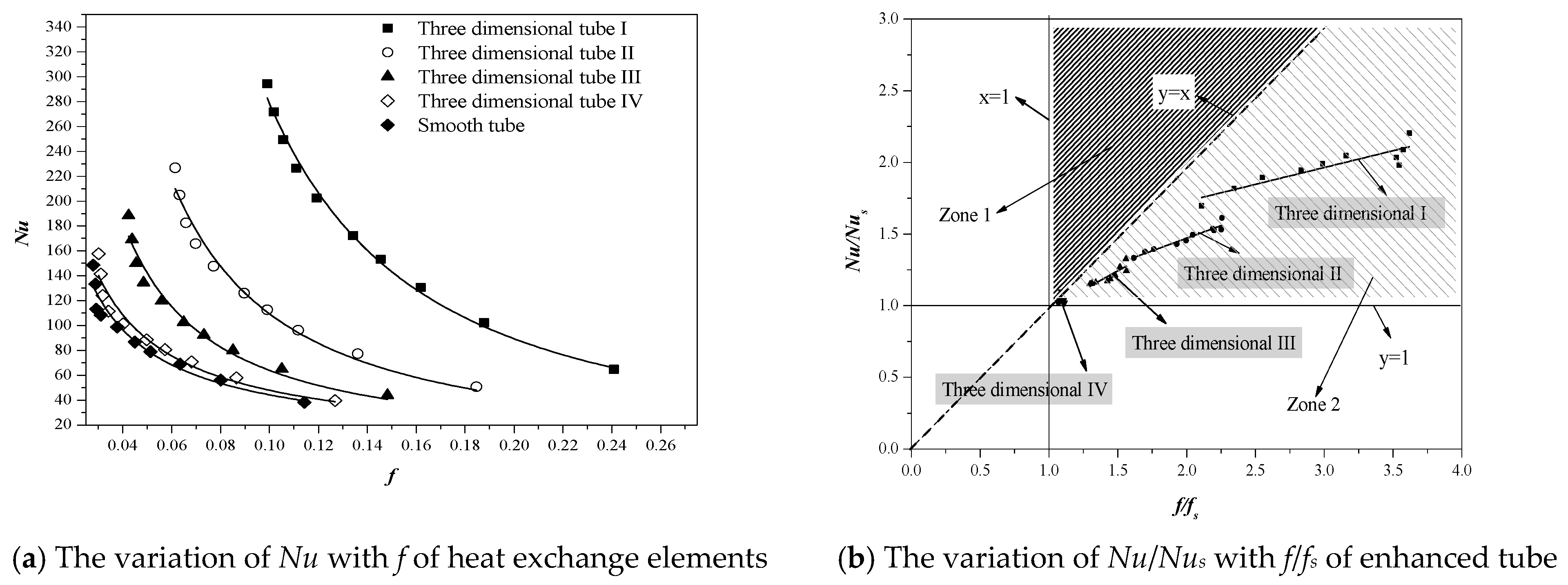
Heat transfer efficiency evaluation method [16]. The heat transfer coefficient and heat transfer capacity of heat exchange elements are the indicators of their heat transfer capacity. In the early enhanced heat transfer research, if researchers only study the increase in heat transfer coefficient, Nu/Nus can be used as the index to evaluate the performance of heat exchange elements.
(2)
Power consumption evaluation method [16]. The flow resistance of the heat exchange element is the index of the power consumption of the pump. For example, researchers only study how to reduce the energy consumption of the heat exchange element, and usually use the resistance coefficient comparison method f/fs as the index of the performance of the heat exchange element.
(3)
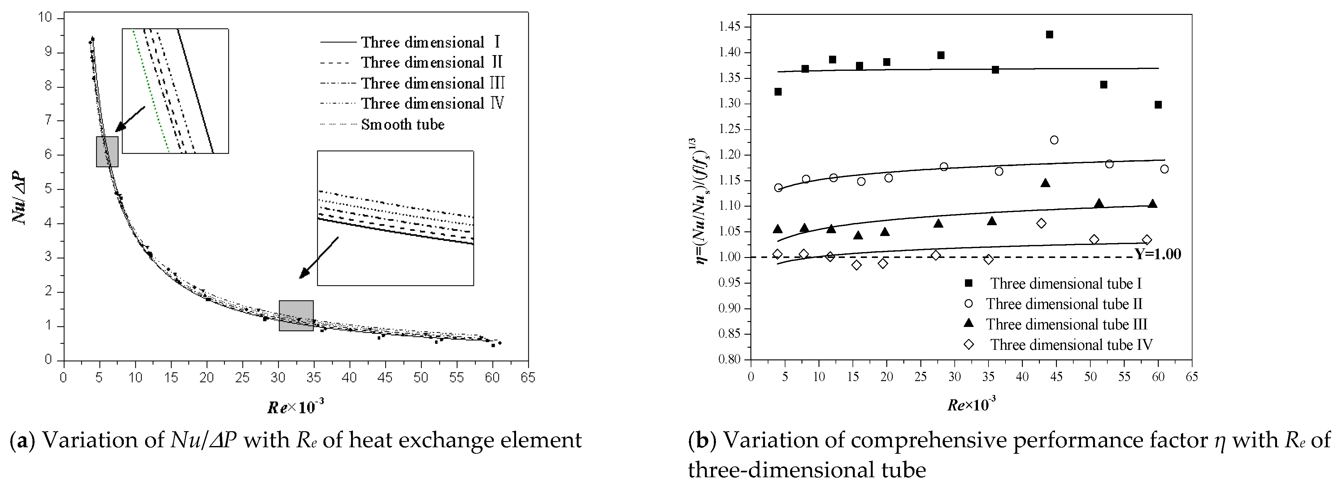
Comprehensive evaluation method of heat transfer and power consumption [17]. The comprehensive performance index of heat exchanger is also under the action of heat transfer and resistance, and NuP is used as the index of heat exchange element performance.
(4)
Performance evaluation criteria method [18]. Webb proposes a method of vertical comparison of heat transfer surface (Performance evaluation criteria (PEC) method), which means that the heat exchange capacity of the pump is compared with the same power transmission condition. The comprehensive performance evaluation index of PEC method is expressed by η. The method has been widely accepted by W.Q. Tao and W.Z. Gu [19,20] et al. The expression of the method is as follows:
η = N u N u s ( f f s ) 1 3
Symbol description: η, comprehensive evaluation factors of heat exchanger, (-); Nus, smooth tube Nusselt number, (-); and fs, smooth tube flow friction coefficient, (-).
(5)
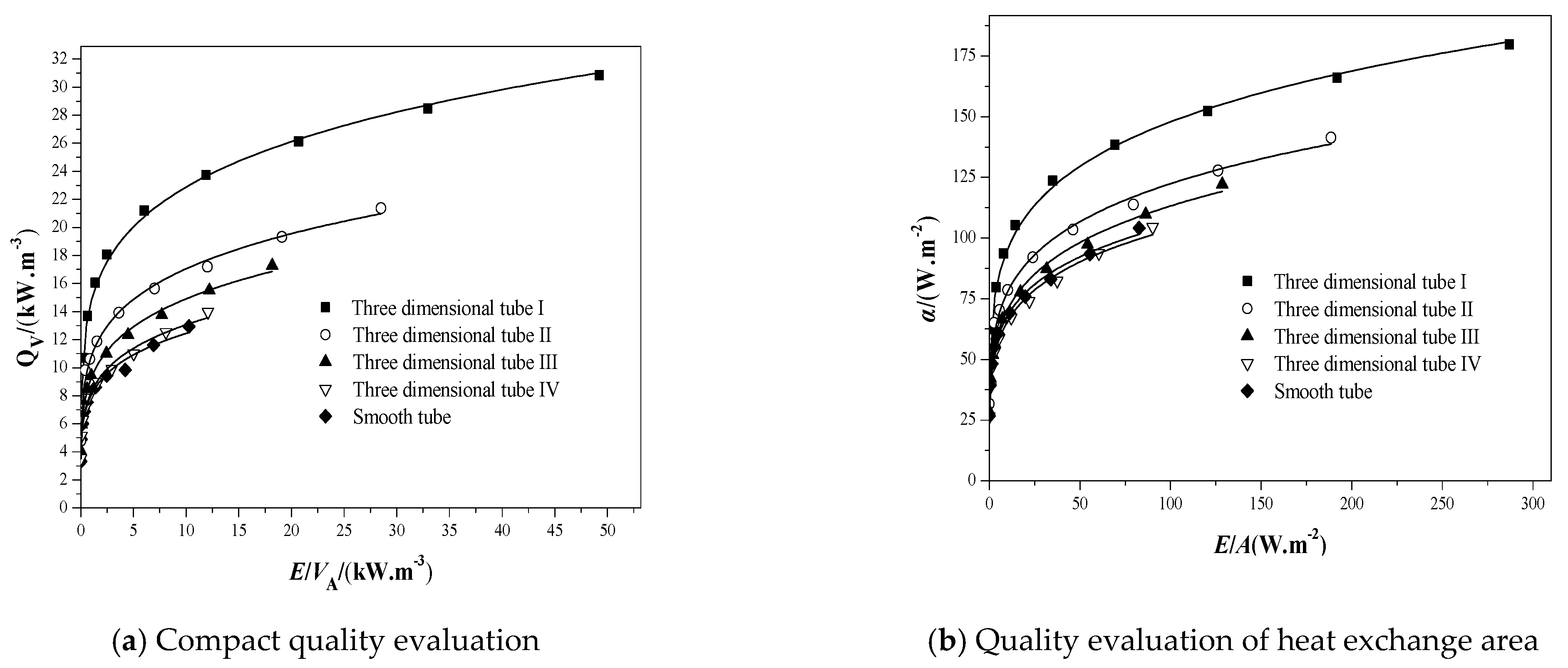
Quality evaluation method of tube bundle compactness [21]. Webb also proposed a quality evaluation method for bundle compactness. Its meaning is to compare the unit volume heat transfer Q with the same unit volume fluid transport power E/V. The higher Q is, the better the compactness of the tube bundle will be. Its expression is as follows:
E V A = Δ P V V A
Symbol description: E, power consumption of fluid transportation, W; and VA, space volume occupied by heat exchange tube, m3.
(6)
Quality evaluation method of heat exchange area of tube bundle [22]. Kays et al. proposed a quality evaluation method of tube bundle heat transfer area, which means that the convective heat transfer coefficient αo is compared with the same unit heat transfer area and fluid transport power consumption E/A. The higher αo, the smaller the heat transfer area required by the structure under the same heat transfer and fluid transport power consumption. Its expression is as follows:
E A = Δ P V A

3.3. Uncertainty Analysis of Experimental System

Because the relative accuracy of the data measured by the experimental system is the basic requirement of the experimental research, the uncertainty analysis of the experimental system is an indispensable part of the experimental research. An experimental system error is caused by the error of the instrument itself, which is related to the error of indirect measurement and direct measurement, so the analysis of the system error is the analysis of the instrument measurements.

3.3.1. Direct Measurement Error Analysis

Before formally collecting data, first start the experimental platform system, debug and correct each instrument, and collect a group of direct measured values x1, x2,…xn of each instrument, respectively. Through these data, the relative error can be analyzed. The analysis process is as follows:
Average of direct measurements:
x ¯ = i = n n x i n
where x ¯ is the average value of the direct measurement value and n is the number of measurements.
Combined with Formula (10), the type A uncertainty can be solved by the following formula:
S D = i = n n ( x i x ¯ ) 2 n ( n 1 )
where SD is the uncertainty of type A.
Combined with Table 3, the type B uncertainty can be obtained from the following formula:
Δ B = ε 3
where ∆B is the uncertainty of type B and ε is the accuracy of the measuring instrument.
The synthetic uncertainty can be solved by Formulas (11) and (12):
Δ x = S D 2 + Δ B 2
Therefore, the relative error of the direct measured value can be solved as follows:
E Direct = Δ x x
where EDirect is the relative error of the direct measured value.
According to Formulas (10)–(14) and Table 3, the relative error of the direct measured value of the instrument of the test platform system can be calculated, as shown in Table 4:

3.3.2. Error Analysis of Indirect Measurement

There is a functional relationship between the error of indirect measurement y and the error of direct measurement x1, x2, …, xn [23].
y = (x1,x2,…,xn)
According to the theory of error transfer, the quadratic formula is used to calculate the error transfer of experimental data. Let Δx1, Δx2, …, Δxn denote the uncertainty of the direct measurement values x1, x2, …, xn, respectively, and Δy is the standard uncertainty of y caused by Δx1, Δx2, …, Δxn, then the following relationship is provided:
Δ y = ( y x 1 Δ x 1 ) 2 + ( y x 2 Δ x 2 ) 2 + + ( y x n Δ x n ) 2
The direct measurement error in the experimental system is mainly caused by the accuracy of the measuring instrument. Therefore, according to the inherent measurement error of the main high-precision measuring instruments such as temperature sensor, differential pressure transmitter, and vortex flowmeter of the experimental system (as shown in Table 3). According to Table 4 and Formulas (15) and (16), the relative error of each indirect measured value can be solved, as shown in Table 5:

4. Analysis of Test Results

4.1. Performance Comparison of Three-Dimensional Tubes and Smooth Tubes with Different Structural Parameters

The four kinds of three-dimensional tubes in this experiment are all made of the base tube with a diameter of Φ32 × 2 mm. The air flows along their axis and is disturbed and destroyed by the special shape structure of the three-dimensional tube, which improves the convective heat transfer coefficient on the air side and strengthens the heat exchange between air and steam. At the same time, the flow loss of air outside the three-dimensional tube is larger than that of the smooth tube for the same reason, the variation rules of Nussel number Nu and friction coefficient f are as follows:
As shown in Figure 4a, in terms of heat transfer performance, with the increase in A/B of cross-section characteristic parameters (when A=B, it is a circular tube), the Nusselt number is correspondingly improved, and increases with the increase in the Reynolds number. The overall performance is as follows: Nu > Nu > Nu > Nu > NuS, among which the performance of type I Nuo is the best, and that of type IV Nuo is the worst. At the biggest gap, type I was 86% higher than type IV and 97% higher than that of the smooth tube. It is shown that the larger the A/B of the cross-section characteristic parameters of the three-dimensional tubes, the more obvious the strengthening effect is. As shown in Figure 4b, with the increase in A/B, the friction coefficient f of the heat exchange element increases correspondingly, and decreases with the increase in the Reynolds number. The overall performance is: f > f > f > f > fS. The friction coefficient of type I is the largest, and that of type IV is the smallest. The friction coefficient of type I at the biggest gap is 229.12% higher than that of type IV and 254.25% higher than that of smooth tube. It shows that when the strengthening effect is obvious, its resistance loss will also increase. Therefore, the above data curve can only reflect the trend of heat transfer characteristics and resistance characteristics of heat exchange elements, and cannot judge whether the enhanced heat exchange elements have engineering value.

4.2. Performance Evaluation and Analysis of Three-Dimensional Tube with Different Structural Parameters

In order to analyze the performance of three-dimensional tubes with different structural parameters more objectively, several evaluation methods approved by most scholars are adopted to analyze the performance variation rules, respectively. As shown in Figure 5a, the curve after the “heat transfer efficiency evaluation method” is adopted. In this method, the ratio of the Nusselt number of each strengthening tube to that of the smooth tube is used to express the strengthening degree of the heat exchange element. From the Re-(Nu/Nus) curve, Nu increases with the increase in Re, but the increase range is small and the slope is small. Under the same flow conditions, the increase in the Reynolds number Re has little effect on the difference of heat transfer performance between the three-dimensional tube and the smooth tube. At the same Reynolds number, the performance rule of Nu/Nus of each enhanced tube heat exchanger is Nu/Nus > Nu/Nus > Nu/Nus > Nu/Nus, of which type I has the most obvious strengthening effect, and type IV has almost no strengthening effect. Type I is 1.98 times that of the light tube, type II is 1.53 times that of the light tube, and type III is 1.27 times that of the light tube. The results further verify that the structural parameter A/B of the three-dimensional tube is one of the important factors affecting the strengthening effect. As shown in Figure 5b, the curve after the “power consumption evaluation method” is adopted. Based on the smooth tube, the ratio of the friction coefficient of each strengthened tube to that of the smooth tube is used to express the flow resistance loss of the heat exchange element. From the Re-(f/fs) curve, f/fs also increases with the increase in the Reynolds number, of which type I has the fastest growth rate, and type IV has almost no change. It shows that the structural parameter A/B of the three-dimensional tube is also one of the important factors affecting the friction coefficient f/fs. Due to the large deformation of the type I three-dimensional tube, the change of f/fs is more obvious with the increase in the Reynolds number Re, indicating that the growth rate of f is large. The shape of type IV is close to the circular tube, and its flow characteristics are also close to the circular tube. Therefore, the change of the Reynolds number Re has no obvious effect on f/fs, and its growth rate is small. At the same Reynolds number, the performance rule of f/fs of each enhanced tube heat exchanger is f/fs > f/fs > f/fs > f/fs.
From the analysis conclusion in Figure 5, this conclusion can only analyze the development trend of heat transfer performance and resistance performance of three-dimensional tubes with different structural parameters, as well as the advantages and disadvantages of their two performances under the same Reynolds number, while ignoring the influence of the two performances on the evaluation of comprehensive performance at the same time.
In order to study the relationship between heat transfer performance and the friction coefficient of heat exchange elements, the Nu-f curve is drawn, as shown in Figure 6a. The heat transfer efficiency decreases with the increase in the friction coefficient. Under the same friction coefficient f, the Nu of type I three-dimensional tube is still the largest, and the influence factor is still the structural parameters of three-dimensional tube. The larger the A/B is, the larger the Nusselt number Nu is. With the increase in the friction coefficient, Nu decreases rapidly at first, and then tends to be flat, which indicates that the influence of friction coefficient f on Nusselt number Nu is limited at high flow rate, and the two trends are opposite. Therefore, Figure 6a cannot clearly show the comprehensive performance law of the three-dimensional tube.
In order to understand the comprehensive performance of heat exchange elements with different structural parameters, Figure 6a is optimized based on the heat transfer coefficient and friction coefficient of the smooth tube, as shown in Figure 6b. According to the literature [16], the straight line y = x through the point (1,1) is the dividing line for evaluating the comprehensive performance of the enhanced tube. The line divides the X-Y axis into two parts, zone 1 and zone 2. The strengthening element in zone 1 indicates that it has better comprehensive performance. According to the situation shown in Figure 6b, all the four types of three-dimensional tubes are in zone 2, so their comprehensive performance does not show the ideal situation, and the results show that the ratio of the heat transfer performance growth rate to the resistance growth rate is a linear slope k, which is less than 1. The law of slope is k k < k < k < k, which indicates that the comprehensive performance of type I is the best among the four types of three-dimensional tubes.
Figure 7 is a curve chart made by using the “compact quality evaluation method” and “heat exchange area quality evaluation method” proposed by scholars Webb and Kays, respectively. It can be seen from the curve in Figure 7a that under the same unit volume fluid transport power consumption E/VA, the performance rule is QV->QV->QV-Ⅲ>QV-Ⅳ>QV-S, in which the heat transfer per unit volume of type I three-dimensional tube is still the highest, and the heat transfer per unit volume of type IV and smooth tube is almost the same, which is about 53.3% lower than that of type I. This shows that the compactness of the type I three-dimensional tube is the best. It can be seen from the curve in Figure 7b that under the same E/A of fluid transport power consumption per unit heat transfer area, the law is similar to that shown in Figure 7a, among which the heat transfer coefficient per unit area of type I three-dimensional tube is the highest, the performance rule is α > α > α > α > αs, this shows that the conclusions of the two evaluation methods are consistent.
Figure 8 shows the comprehensive performance evaluation of four types of three-dimensional tubes using Wang Shuangying’s “comprehensive evaluation method of heat transfer and power consumption” and Webb’s “performance evaluation criteria method”. As shown in Figure 8a, NuP decreases with the increase in Re, and the trend and distance of curves representing several three-dimensional tubes are very close, which indicates that although changing the shape structure parameter A/B can improve the heat transfer performance of three-dimensional tubes, it also increases the flow resistance, and the ratio of heat transfer coefficient and flow resistance of each heat exchange element is similar. Among them, the performance of type I is slightly better than that of the four types, indicating that the larger the A/B ratio is, the better the comprehensive performance is. As shown in Figure 8b, it is a curve diagram based on the “performance evaluation criteria method” proposed by Webb to comprehensively evaluate the thermal effect, flow resistance, cost and operating cost. It can be seen from the figure that from the trend of curve Re-η, with the increase in Re, the comprehensive performance evaluation factors η of the four kinds of three-dimensional pipes have little change, but almost all of them are above the straight line Y = η = 1, which indicates that all three-dimensional tubes meet the strengthening requirements. Among them, the type I evaluation value of η = 1.37 is the most prominent, while the type IV average value of η = 1.02 is the worst, almost without obvious enhancement. The rule of their performance is η > η > η > η, which indicates that the larger the A/B ratio is, the better the comprehensive performance is. Although the expressions of the conclusions obtained by the two comprehensive performance evaluation methods in Figure 8 are different, the final results are consistent.

5. Conclusions

Through experiments and theoretical analysis, the comprehensive performance of three-dimensional tube strengthening with different structural parameters is investigated, and different comprehensive performance evaluation methods are used for evaluation and comparison, the conclusions are as follows:
(1)
Under the same conditions, due to the different research focuses of researchers, the requirements for the performance evaluation form are also different. The choice of evaluation method is related to the research purpose of researchers. According to the analysis results, the reliability of the comprehensive performance evaluation method of “performance evaluation criteria method “is relatively high;
(2)
At the same Reynolds number Reo, the larger the structure parameter A/B, the better the heat transfer performance, but the larger the flow resistance;
(3)
The structure parameter A/B of three-dimensional tube has great influence on its comprehensive performance. The results show that the larger the A/B ratio is, the better the comprehensive performance is. With the increase in the A/B ratio, the growth rate of the heat transfer performance of the three-dimensional tube is larger than that of the flow resistance;
(4)
Among the four kinds of three-dimensional tubes, the comprehensive performance factors are as follows: η>η>η>η, and the best comprehensive performance was shown in the type I three-dimensional tube.

Author Contributions

Conceptualization, D.-S.Z.; methodology, X.M. and A.-M.T.; software, X.-Z.L. and X.M.; validation, X.M. and A.-M.T.; analysis, X.M. and S.-J.L.; Writing—original draftpreparation, X.M. and S.-J.L.; writing—review and editing, A.-M.T. and S.-J.L.; Supervision, D.-S.Z. and A.-M.T.; project administration, A.-M.T.; funding acquisition, X.M. and S.-J.L. All authors have readand agreed to the published version of the manuscript.

Funding

This research was supported by the Natural Science Foundation of Guangdong Province (No. 2020A1515011318); the Science and Technology Special Project of Guangdong Province (No. 2020ST008); the Science and Technology Innovation Project of Foshan National High-tech Zone (No. 2020197000618); and the Guangdong Provincial Key Laboratory of New and Renewable Energy Research and Development.

Institutional Review Board Statement

Not applicable.

Informed Consent Statement

Not applicable.

Data Availability Statement

The relevant experimental data is provided by the Key Laboratory of Renewable Energy, Chinese Academy of Sciences and the Guangdong Key Laboratory of New and Renewable Energy Research and Development in China.

Acknowledgments

We sincerely acknowledge the Key Laboratory of Renewable Energy, Chinese Academy of Sciences and the Guangdong Key Laboratory of New and Renewable Energy Research and Development for providing the relevant experimental data.

Conflicts of Interest

The authors declare no conflict of interest.

Nomenclature

PPitch of three-dimensional tube (mm)
ALong axis of three-dimensional tube (mm)
BThe minor axis of three-dimensional tube (mm)
doOutside diameter of smooth tube (mm)
diInner diameter of smooth tube (mm)
LLength of heat exchange element (mm)
äWall thickness of heat exchange element (mm)
QHeat exchange of heat exchanger (W)
NuNusselt number (-)
ReReynolds number (-)
PFlow resistance loss (Pa)
fFlow friction coefficient (-)
kRatio of heat transfer performance growth rate to resistance growth rate (-)
deEquivalent diameter (m)
cSpecific heat of working fluid at constant pressure (J kg−1 K−1)
ASurface area of heat exchange element (m2)
TWorking fluid temperature (K)
T ¯ Average temperature difference of working fluid (K)
VVolume flow of working fluid (m3 s−1)
CHeat transfer perimeter(m)
leEquivalent length of heat exchange element (m)
vFlow rate of working fluid (m s−1)
FFlow area (m2)
S1transverse pitch (mm)
EDirectThe relative error of the direct measured value
x ¯ The average value of the direct measurement value
nThe number of measurements
S2longitudinal pitch (mm)
NuNusselt number (-)
EPower consumption of fluid transportation (W)
VASpace volume occupied by heat exchange tube (m3)
xDirect measurement
yIndirect measurement
ΔxAbsolute error of direct measurement value
ΔyStandard uncertainty
ΔBThe uncertainty of type B
fFriction coefficient (-)
SDThe uncertainty of type A
subscript
1Inlet
2Outlet
wTube wall
VaporSteam
IThree-dimensional tube 1
IIThree-dimensional tube 2
IIIThree-dimensional tube 3
IVThree-dimensional tube 4
sSmooth tube
Greek symbols
δWall thickness of heat exchange element (mm)
ηComprehensive evaluation factors of heat exchanger
áConvective heat transfer coefficient of heat exchange element (W m−2 K−1)
λThermal conductivity of working fluid (W m−1 K−1)
εThe accuracy of the measuring instrument
ρDensity of working fluid (kg m−3)

References

  1. Yin, Y.D.; Zhu, D.S.; Sun, J.F.; Li, X.Z.; Zhang, J.N.; Lin, C.D. Comparison of a novel un-baffled and a conventional shell-and-tube dry-expansion evaporator. Appl. Therm. Eng. 2017, 113, 1137–1145. [Google Scholar] [CrossRef]
  2. Yin, Y.; Zhu, D.; Sun, J.; Li, X.; Tu, A. Experimental Investigation of Evaporative Condensed Refrigerating System by Variation of Heat Transfer Tube Types. Procedia Eng. 2017, 205, 175–182. [Google Scholar] [CrossRef]
  3. Li, X.; Zhu, D.; Yin, Y.; Liu, S.; Mo, X. Experimental study on heat transfer and pressure drop of twisted oval tube bundle in cross flow. Exp. Therm. Fluid Sci. 2018, 99, 251–258. [Google Scholar] [CrossRef]
  4. Li, X.; Zhu, D.; Yin, Y.; Tu, A.; Liu, S. Parametric study on heat transfer and pressure drop of twisted oval tube bundle with in line layout. Int. J. Heat Mass Transf. 2019, 135, 860–872. [Google Scholar] [CrossRef]
  5. Li, X.; Zhu, D.; Sun, J.; Mo, X.; Yin, Y. Air side heat transfer and pressure drop of H type fin and tube bundles with in line layouts. Exp. Therm. Fluid Sci. 2018, 96, 146–153. [Google Scholar] [CrossRef]
  6. Mo, X.; Zhu, D.S.; Wang, F.Y.; Yin, Y.D. Study on heat transfer and fluidity of three-dimensional invisible finned-tube heat exchanger. J. Therm. Anal. Calorim. 2020, 5, 1–2. [Google Scholar]
  7. Mo, M.; Zhu, D.; Lin, C. Experimental and Numerical Research on Heat Transfer Characteristics of Three-dimensional Flue Gas Heat Exchanger. Chin. J. Process Eng. 2018, 18, 41–48. [Google Scholar]
  8. Mo, X.; Zhu, D.S.; Lin, C.; Deng, W. Research on resistance and flow field characteristics of three-dimensional tubes. Chem. Eng. 2020, 48, 74–78. [Google Scholar]
  9. Yang, L. Numerical Simulation and Experimental Research on Heat Transfer Performance of Twisted Tube Double Shell Side Heat Exchanger; South China University of Technology: Guangzhou, China, 2010; pp. 54–67. [Google Scholar]
  10. Yu, C.; Zhang, H.; Wang, Y.; Zeng, M.; Gao, B. Numerical study on turbulent heat transfer performance of twisted oval tube with different cross sectioned wire coil. Case Stud. Therm. Eng. 2020, 22, 100759. [Google Scholar] [CrossRef]
  11. Dong, X.; Jin, X.; Li, P.; Bi, Q.; Gui, M.; Wang, T. Experimental research on heat transfer and flow resistance properties in spiral twisted tube heat exchanger. Appl. Therm. Eng. 2020, 176, 115397. [Google Scholar] [CrossRef]
  12. Guo, W. Newton’s law of cooling and its practical application. China New Telecommun. 2019, 21, 244. [Google Scholar]
  13. Dittus, F.W.; Boelter, L.M.K. Heat Transfer in Automobile Radiators of the Tubular Type. Heat Mass Transf. 1985, 12, 3–22. [Google Scholar] [CrossRef]
  14. Kim, I.H.; No, H.C. Thermal Hydraulic Performance Analysis of a Printed Circuit Heat Exchanger Using a Helium–water Test Loop and Numerical Simulations. Appl. Therm. Eng. 2011, 31, 4064–4073. [Google Scholar] [CrossRef]
  15. Chen, M.; Sun, X.; Richard, N.C.; Isaac, S.; Vivek, U.; Piyush, S. Pressure Drop and Heat Transfer Characteristics of a High-temperature Printed Circuit Heat Exchanger. Appl. Therm. Eng. 2016, 108, 1409–1417. [Google Scholar] [CrossRef] [Green Version]
  16. Fan, J.F.; Ding, W.K.; Zhang, J.F.; He, Y.L.; Tao, W.Q. A performance evaluation plot of enhanced heat transfer techniques oriented for energy-saving. Int. J. Heat Mass Transf. 2009, 52, 33–44. [Google Scholar] [CrossRef]
  17. Wang, Y. Theoretical and Experimental Studies of Fluid Flow and Heat Transfer for Logitudinal Flow Shell-and-Tube Heat Exchanger; Huazhong Huazhong University of Science and Technology: Wuhan, China, 2011; pp. 97–117. [Google Scholar]
  18. Webb, R.L. Performance evaluation criteria for use of enhanced heat transfer surfaces in heat exchanger design. Pergamon 1981, 24, 715–726. [Google Scholar] [CrossRef]
  19. Tao, W.; He, Y. Field Synergy Principle and Its Applications in Enhancing Convective Heat Transfer and Improving Performance of Pulse Tube Refreigerator (1). J. Xi’an Jiaotong Univ. 2002, 36, 1101–1105. [Google Scholar]
  20. Gu, W.; Shen, J.; Ma, C.; Zhang, Y. Enhanced Heat Transfer; Science Press: Beijing, China, 1990; pp. 9–21. [Google Scholar]
  21. Webb, R.L.; Kim, N.H. Principle of Enhanced Heat Transfer, 2nd ed.; Taylor & Francis: Borca Raton, UK, 2005; p. 28. [Google Scholar]
  22. Kays, W.M.; London, A.L. Compact Heat Exchangers, 3rd ed.; McGraw Hill: New York, NY, USA, 1984. [Google Scholar]
  23. Moffat, R.J. Using uncertainty analysis in the planning of an experiment. J. Fluids Eng. 1985, 107, 173–178. [Google Scholar] [CrossRef]
Figure 1. Flow chart of the heat exchanger test system. 1. Test prototype I; 2. test prototype Ⅱ; 3. temperature sensor; 4. pressure transmitters; 5. control valve; 6. particle filling hopper; 7. vortex flowmeter; 8. blower; 9. gas-fired boiler; 10. booster pump; and 11. steam condenser.
Energies 14 05274 g001
Figure 2. Heat exchanger test prototype.
Energies 14 05274 g002
Figure 3. Schematic diagram of three-dimensional tube shape.
Energies 14 05274 g003
Figure 4. Curves of Nu and f outside three-dimensional tube changing with Re.
Energies 14 05274 g004
Figure 5. Curves of Nu/Nus and f/fs outside three-dimensional tube changing with Re.
Energies 14 05274 g005
Figure 6. Curves of Nu and Nu/Nus outside three-dimensional tube changing with f and f/fs.
Energies 14 05274 g006
Figure 7. Comparison of spatial volume saving and heat transfer area saving among four types of tube.
Energies 14 05274 g007
Figure 8. Curves of NuP and η outside three-dimensional tube changing with Re.
Energies 14 05274 g008
Table 1. Main instruments used in the test.
NO.NameMeasuring Point/OthersPurposeQuantity
1Temperature sensorOutside tube inlet/outletMedium temperature5
2Differential pressure transmitterOutside tube inlet/outletFluid pressure outside the tube5
3Vortex FlowmeterOutside tube outletFluid flow outside the tube1
4Blower≥1500 m3/hAir pressurization1
5Boiler1 t/hProvide steam source1
Table 2. The main shape parameters of three-dimensional tube and smooth tube.
NO.Heat Exchange ElementBase TubeLPA/BPitch
(S1 = S2)
δ
do/di
1Three-dimensional tube Iφ32150020040/18402
2Three-dimensional tube IIφ32150020038/21402
3Three-dimensional tube IIφ32150020036/25402
4Three-dimensional tube IVφ32150020034/28402
5Smooth tubeφ321500/32/28402
Table 3. Application range and accuracy of measuring instruments.
NO.Test ParametersTest InstrumentInstrument Accuracy
1Air inlet/outlet temperatureTemperature sensorRange: 0–300 °C, accuracy: ±0.3 °C;
2Steam inlet/outlet temperatureTemperature sensorRange: 0–300 °C, accuracy: ±0.3 °C;
3Air inlet/outlet pressure differenceDifferential pressure transmitterRange: 0–2000 Pa, accuracy: ±2 Pa
4Air flow inletVortex flowmeterRange: 10–1500 m3/h, accuracy: ±7 m3/h
Table 4. The relative error of the direct measured value of the instrument in the experimental platform system.
No.NameAverage ValueType A UncertaintyType B UncertaintySynthetic UncertaintyTruth ValueRelative Error
1Symbol x ¯ SDΔB = ε/ 3 ΔxxEDirect = Δx/x
2T120.860.097440.173200.1987320.80.95%
3T2113.180.087920.173200.19424113.10.17%
4Tvapour209.890.104240.173200.20215209.80.10%
5ΔP255.100.575371.154701.29011255.10.51%
6V93.250.914434.041454.1436193.24.45%
Table 5. The relative error of the indirect measured value of the instrument in the experimental platform system.
No.NameExpressionRelative Error ExpressionRelative Error
1 T ¯ T ¯ = T 1 + T 2 2 Δ T ¯ T ¯ = ( T ¯ T 1 Δ T 1 ) 2 + ( T ¯ T 2 Δ T 2 ) 2 T ¯ = ( Δ T 1 ) 2 + ( Δ T 2 ) 2 2 T ¯ 0.21%
2Q Q = V o ρ o c o ( T 2 T 1 ) Δ Q Q = ( Q V Δ V ) 2 + ( Q T 1 Δ T 1 ) 2 + ( Q T 2 Δ T 2 ) 2 Q = [ ( T 2 T 1 ) Δ V ] 2 + [ V Δ T 1 ] 2 + [ V Δ T 2 ] 2 V ( T 2 T 1 ) 4.45%
3α α = V ρ c ( T 2 T 1 ) ( T v a p o u r T ¯ ) A Δ α α = ( α V Δ V ) 2 + ( α T 1 Δ T 1 ) 2 + ( α T 2 Δ T 2 ) 2 + ( α T v a p o u r Δ T v a p o u r ) 2 + ( α T ¯ Δ T ¯ ) 2 α = [ ( T 2 T 1 ) Δ V ] 2 + [ V Δ T 1 ] 2 + [ V Δ T 2 ] 2 + ( V ( T 2 T 1 ) ( T v a p o u r T ¯ ) Δ T v a p o u r ) 2 + ( V ( T 2 T 1 ) ( T v a p o u r T ¯ ) Δ T ¯ ) 2 V ( T 2 T 1 ) 4.45%
4Nu N u = α d e λ Δ N u N u = Δ α α 4.45%
5f f = Δ P l e d e ρ V 2 2 × 3600 2 × F 2 Δ f f = ( f ( Δ P ) Δ ( Δ P ) ) 2 + ( f V Δ V ) 2 f = [ Δ ( Δ P ) ] 2 + [ ( 2 Δ P V ) Δ V ] 2 Δ P 0.51%
Publisher’s Note: MDPI stays neutral with regard to jurisdictional claims in published maps and institutional affiliations.

