Article

Effect of Adding Emulsifier to Fuel on Work Efficiency and Gas Turbine Emissions

Department of Division of Aircraft Engines, Warsaw University of Technology, 00-661 Warsaw, Poland
*
Author to whom correspondence should be addressed.
Energies 2021, 14(17), 5255; https://doi.org/10.3390/en14175255
Submission received: 9 July 2021 / Revised: 20 August 2021 / Accepted: 21 August 2021 / Published: 25 August 2021

Abstract

:
In an effort to reduce the emissivity of transport and energy, numerous studies are being carried out on the impact of the combustion of alternative fuels on the emission and operating parameters of propulsion and energy units. One of the observed trends is the use of emulsion fuels. The addition of an emulsifier to an emulsion fuel reduces the interfacial tension between two liquids, which allows obtaining an emulsion fuel with the expected stability. The research conducted on self-ignition engines and gas turbines (TG) does not give an unambiguous answer as to the influence of the use of fuel-water emulsion on CO emissions. One of the reasons for the discrepancy in the obtained results may be the type and amount of the emulsifier used in the emulsion fuel. Tests were carried out on the GTM-120 gas turbine to compare the operating parameters and emissions between the cases in which TG was supplied with three fuel mixtures—the standard fuel for TG (DF) and DF with 2% and 5% emulsifier addition. It was shown that the addition of 2% of the emulsifier to DF causes an increase in CO emission, with the remaining measured parameters unchanged. On the other hand, increasing the amount of emulsifier in DF to 5% reduces CO emissions to the level observed in the case in which DF was burned reduces NOx emissions and reduces the thermal efficiency of TG.

1. Introduction

Currently, numerous studies are being conducted on the reduction of the emission of undesirable combustion products from internal combustion engines [1,2,3,4,5,6,7]. One of the trends in the research is the use of fuel-water emulsion (FWE), which is evidenced by the increase in the number of published scientific papers on this topic. From 2009 to 2019, the annual number of publications on FWE increased fivefold [8]. In the FWE production process, an important role is played by a surfactant whose task is to reduce the interfacial tension, which allows obtaining FWE with greater durability [9]. The type and amount of surfactant used in the production of FWE affects the micro- and macroscopic properties of the mixture [10,11,12]. By changing the type of emulsifier and its quantity, it is possible to influence the size of the water droplets contained in the FWE and its durability [10,12]. Increasing the amount of emulsifier in the FWE also allows for obtaining emulsions with greater stability or with a higher water content and comparable stability to the base case [11]. On the other hand, the amount of water in the FWE affects the evaporation time of the FWE droplets [13] and the intensity of the micro-explosion process [14,15]. The phenomenon of micro-explosion causes greater fragmentation of fuel droplets, which in turn leads to better mixing of the fuel with the oxidant. The size of the water droplets contained in the FWE affects the combustion parameters and emissions. In [16], differences were noted in the value of torque and power between the case in which the diesel engine was powered by emulsion and nano-emulsion fuels. The use of nano-emulsion fuel led to a reduction of CO emissions by 11.64%, and the use of emulsion fuel by 4.36% compared to the reference case. Studies conducted on single FWE droplets prove that the emulsifier actively participates in the combustion process [17,18]. After completion of the micro-explosion phenomenon, which is one of the stages of the emulsion fuel combustion, the surfactants combustion is observed [17]. Emulsifiers are also used in the process of blending fuel with nano- and micro-metal particles. In the experimental studies of a single fuel drop (n-decane + 10% nano aluminium particles + 2.5% emulsifier), similarly to [17], the fuel droplet combustion phase was observed, during which the surfactant was burnt [18]. The experimental study on the combustion of foamed emulsion proves that the amount of emulsifier in the mixture affects the burning rate and this parameter has one maximum depending on the amount of emulsifier [19]. Thus, it is important to find the optimal amount of surfactant in order to maximize the combustion process. It is believed that FWE has a potential application as an alternative fuel in compression ignition engines [20]. The addition of water to the fuel in the form of FWE leads to the reduction of NOx emissions and the temperature of exhaust gases in this type of drive units [20,21,22,23,24]. However, the review work in the conclusions was inconsistent as to the impact of FWE on CO emissions. In [20], an increase in CO emissions is indicated as a result of adding water to fuel, while in [21,22,23], it is concluded that the impact of FWE on CO emissions is ambiguous.
Research is also conducted on the effect of feeding gas turbines with FWE. In gas turbines (TG), there is a tendency to lower the temperature of the exhaust gases and reduce NOx emissions [25,26,27,28,29,30]. However, as is the case with reciprocating units, there are also discrepancies in the studies regarding the impact of FWE on CO emissions. In [25,26], a decrease in NOx emissions and an increase in CO emissions were recorded, with no increase in the temperature of the exhaust gases due to the application of FWE. On the other hand, [27] presents tests carried out on a combustion chamber normally supplied with Jet-A1 fuel, which showed a reduction in the temperature of the exhaust gases, lower NOx emission, but also a simultaneous reduction of CO emissions in the case of feeding the FWE chamber with 2.5% water content [27]. Also, in the research conducted on a miniature gas turbine fuelled by Jet-A1 and emulsion fuels with a water content of 3–12%, a simultaneous reduction in CO and NOx emissions was noted for all tested water contents in the FWE compared to the case in which TG was powered by Jet-A1 fuel. At the TG design point of operation, a simultaneous reduction of NOx and CO emissions by 17.86% and 7.2% was achieved, and a reduction of fuel consumption by 5.46% [30]. The reasons for obtaining different results of experimental studies on the influence of FWE on CO emission are not clearly defined. It is emphasized in [23] that the influence of the emulsifier on the emission from compression ignition engines has not been investigated, and in [24] it is indicated that there is a relatively small number of studies on the influence of the emulsifier on the combustion process and emissions. However, in [21,22] it is noted that large discrepancies in the studies on the influence of FWE on CO and HC emission may be caused by different quality of FWE and the amount of different additives to FWE. The type and amount of the emulsifier in the mixture affects the micro- and macroscopic parameters of the resulting fuel mixture [10,11,12], therefore, it is a factor that can be used to design FWE properties. Moreover, it actively participates in the FWE combustion process [17,18]. In the study on the effect of water droplet size in FWE presented in [16], where this effect was noted, the change in water droplet size was obtained by changing the amount of emulsifier from 2% to 5%. On the other hand, in the study concerning the comparison of operating parameters and emissions from a diesel engine after the use of FWE produced with the use of two different types of emulsifiers, presented in [12], the durability of FWE was used as a criterion for the amount of emulsifier addition. Consequently, the compared FWE were produced with the use of different amounts of emulsifier and characterized by different sizes of water droplets in the produced fuel mixtures.
In this study, the effect of adding an emulsifier to the fuel on the combustion process and emissions in the miniature gas turbine GTM-120 was investigated. In order to eliminate the influence of other factors on the combustion process, in addition to the amount of emulsifier, fuel mixtures were used, which consist only of a standard fuel mixture (DF) and an emulsifier. Experimental studies were carried out for cases in which TG was fueled with DF, DF with 2% addition of emulsifier (S2), and DF with 5% content of emulsifier (S5).

2. Test Stand and Fuel Mixtures

2.1. Test Stand

The subject of the research was the GTM-120 gas turbine. It is a single-shaft unit with a single-stage radial compressor, a single-stage turbine and a quasi-reverse flow combustion chamber [31,32]. The gas turbine (TG) with the test stand is shown in Figure 1. In Figure 1, the TG with the connected sensors is marked with Figure 1a, and its close-up is also shown in the frame. The TG is equipped with a thermocouple enabling temperature measurement in the flow between the outlet from the combustion chamber and the grid of the turbine guide vanes. A K-type thermocouple (NiCr-NiAl) was used, and its measurement accuracy was ±0.4% of the measured temperature value. The TG was placed on a bearing platform that allowed for movement along the axis of the tested unit, which made it possible to measure the thrust using a strain gauge beam with a total measurement uncertainty of ±0.55 N. Modified for the needs of the experiment, the factory TG housing also allows for measurements of the temperature, total and dynamic pressure in the inlet section, temperature and pressure downstream of the compressor diffuser, pressure in the plane of the outlet from the combustion chamber, and temperature in the outlet section of the turbine nozzle. The gas fuel tank is marked with Figure 1b. In the initial stage of start-up, TG GTM-120 is fed with gaseous fuel due to its easier ignition than liquid fuels. Combustion of gaseous fuel during the start-up is stopped at the moment when the temperature in the combustion chamber of the gas turbine is reached that allows the liquid fuel to evaporate. After these conditions are achieved, the TG is supplied only with liquid fuel from the tank marked in Figure 1c. The liquid fuel tank is equipped with a differential pressure sensor that measures the difference between the ambient pressure and the pressure of the liquid column. The change in voltage on the pressure transducer caused by the change in the pressure of the liquid column during the test was recorded in real time. The sensors used to measure the thrust and fuel consumption allow for the calculation of thrust-specific fuel consumptions (TSFC) with the complex standard uncertainty of ±0.045 kg/(N × h) (80k rpm) calculated by the total differential method. All the above-mentioned parameters were recorded at a frequency of 40 Hz. The in Figure 1d indicates the Testo 350 exhaust gas analyzer, the probe of which is located in the plane of the outlet from the TG nozzle. Details of the sensors with which the exhaust gas analyzer was equipped are included in Table 1. The presented resolutions and accuracy of measurements correspond to the emission range in which the experimental tests were conducted. Data acquisition from the exhaust gas analyzer was carried out in real time with a frequency of 1 Hz.
During all experimental tests, the position of each sensor and probe of the exhaust gas analyzer was unchanged. Details of the experimental test procedure are described in [30].

2.2. Fuel Mixtures

The tests were carried out with the use of three fuel mixtures. The mass fraction of the individual components of the tested fuel mixtures is presented in Table 2. The GTM-120 gas turbine does not have a closed lubrication system, the bearings are lubricated with fuel from the liquid fuel tank (Figure 1c). In order to increase the lubricating properties, an oil admixture of Jet-A1 is used. In the presented tests, AeroShell Turbine Oil 500 was used.
The emulsifier used is a five-component mixture consisting of four different surfactants and demineralized water. Table 3 shows the percentage mass fraction of the individual components in the emulsifier, the table uses the trade names of surfactants. All emulsifiers included in the emulsifier prepared for the research purposes were produced by PCC SE, and their safety data sheets are available in [33].
The emulsifier developed for the purpose of the research is a homogeneous brown-colored mixture (Figure 2a). Fuel mixtures made by adding an emulsifier to DF are also homogeneous mixtures. Figure 2b presents a microscopic photo of S2, showing no separation of the emulsifier from DF. The emulsifier used in the research is fully functional and allows for the formation of stable fuel-water emulsions. An emulsion with a 3% water content and 2% emulsifier is shown in Figure 2c, while Figure 2d shows a microscopic photo of an emulsion containing 9% water and 3% emulsifier.

3. Experimental Research

A total of 33 experimental trials were carried out. For the case in which TG was supplied with DF, 14 tests were performed, for the case of S2—10 tests, and for the variant S5—9 tests. The experimental tests were carried out in the temperature range of 16.3 °C ÷ 24.7 °C and pressures of 982 hPa ÷ 1015 hPa. The useful RPM range of the TG GTM-120 is from 33k rpm at idle to 120k rpm. The measurement data were recorded in five steady states of the engine corresponding to 40k, 60k, 80k, 100k and 120k rpm. The engine speed control accuracy in the range of 40k ÷ 100k rpm was ±600 rpm, while for the measuring point of 120k rpm, +0 rpm ÷ −6k rpm. In each of the steady states, the TG was held for 90 s. All tests were conducted according to the same procedure in order to eliminate additional errors. In each of the presented graphs, the vertical error bars correspond to the standard deviation, and the horizontal error bars correspond to the rotational speed control accuracy.

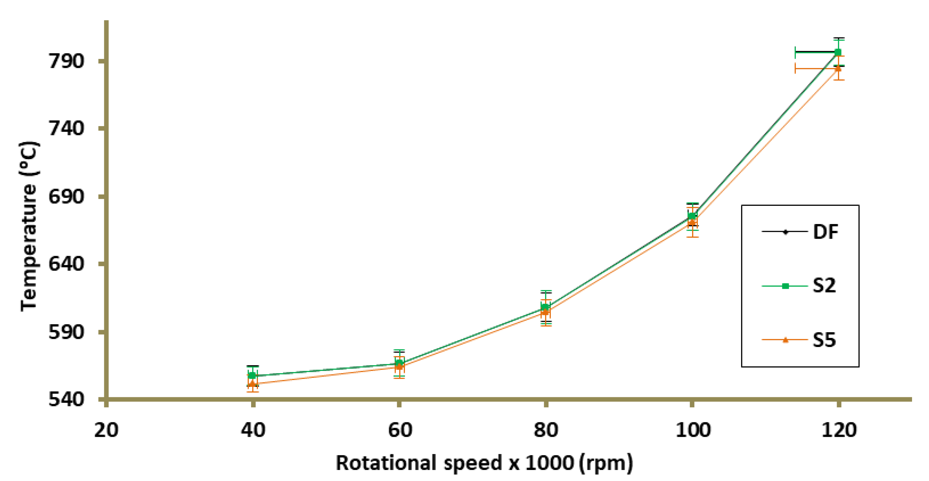
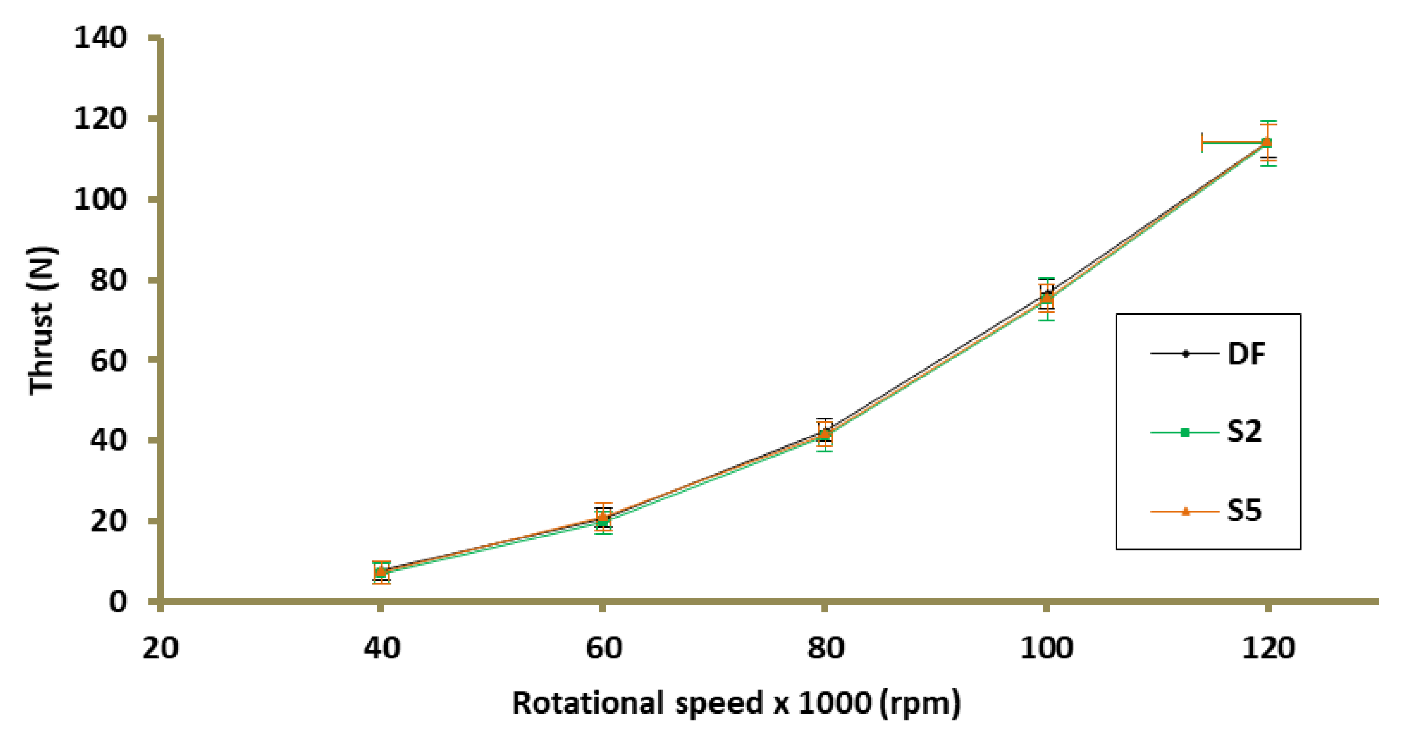
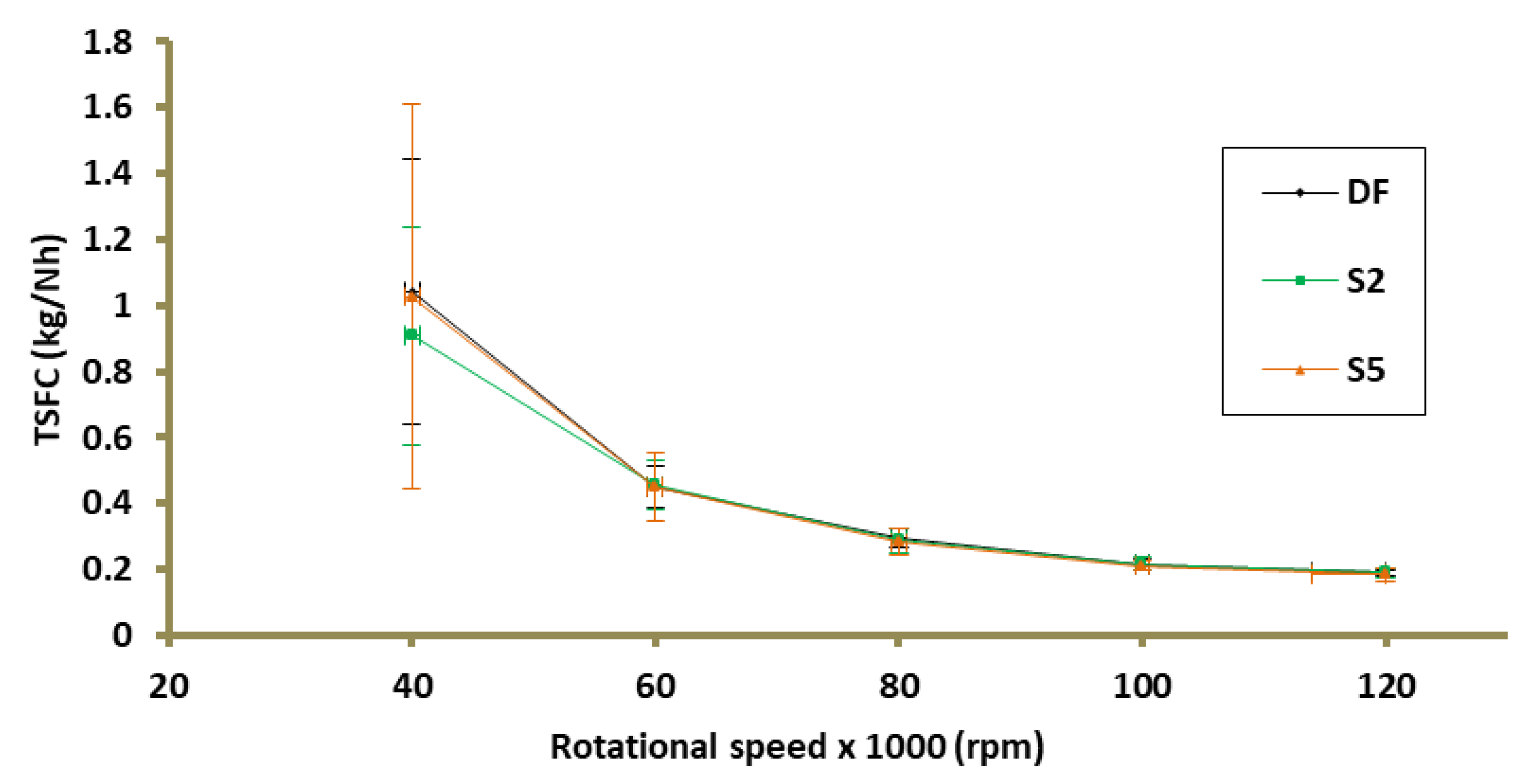
3.1. Working Parameters TG
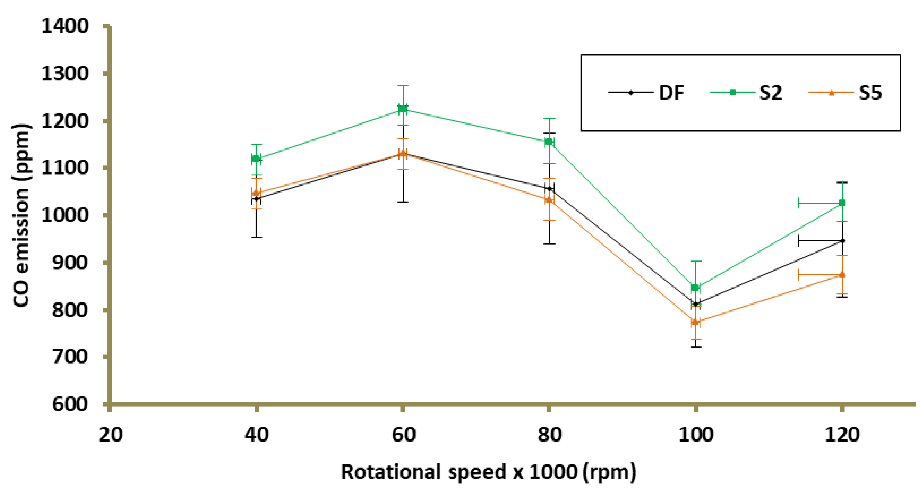
Figure 3 shows the results of the temperature measurement downstream of the combustion chamber (T4) for the cases of supplying TG, DF, and fuels with the addition of surfactant, in two variants. The maximum difference in average recorded temperatures between the DF case and the modified fuels was 1.4 °C (100k rpm) and 11.9 °C (120k rpm) for S2 and S3, successively. At the measuring point corresponding to 80k rpm, which is the nominal TG operating point [34], the temperature difference between the case in which TG was supplied to DF and S2 did not exceed 1 °C. On the other hand, the use of a fuel mixture containing 5% of the emulsifier caused a temperature drop by 4 °C in relation to the DF at the same measuring point (Figure 6a).
The registered difference in the generated thrust between the DF and the compared mixtures did not exceed 1.7 N (Figure 4). It was recorded at the test point where the turbine was running at a rotational speed of 80k rpm for S2. This is a 3.9% decrease in the generated thrust compared to the reference case. In the case of supplying TG with the S5 fuel mixture, the thrust reduction for the same rotational speed did not exceed 2.5% (Figure 6b).
Figure 5 shows thrust-specific fuel consumptions (TSFC) depending on the rotational speed of the gas turbine. TSFC is defined as the amount of DF required to generate one Newton in one hour. The maximum difference with respect to the DF that was noted in the TSFC did not exceed 0.014 kg/(N × h). For the regime corresponding to the design TG work point (80k rpm), a change in TSCF by 2.5% and 4.6% was recorded for S2 and S5, successively in relation to DF (Figure 6c). As the load on the gas turbine decreased, the standard deviation of TSCF increased. This is due to the limitations of the TG controller, which is able to maintain the set turbine revolutions with a certain accuracy that does not change with the change of the load of the controlled unit. Consequently, the standard deviations of the thrust, in absolute values, for the entire measuring range do not change significantly, while their relative values are the greater the smaller the thrust generated by the TG. A similar relationship between the measurement uncertainty of TSFC and the engine load was reported in [35].

3.2. Emission

Figure 7 shows NOx (NO + NO2) emissions as a function of TG rotations for DF, S2, and S5 fuel mixtures. The maximum difference in NOx emissions between DF and S2 was 0.4 ppm, it was recorded at 60k rpm. On the other hand, the use of S5 fuel resulted in a reduction of NOx emissions by 1.9 ppm at the measuring point of 120k rpm. At the design point of operation TG (80k rpm), the use of fuel additives resulted in a decrease in NOx emissions by 1.6% and 5.1% for cases S2, S5, successively (Figure 11a).
For the case of using S2 as a fuel, an increase in CO emissions was recorded at all analyzed measuring points (Figure 8). The maximum increase in CO emission for the case of S2 against DF was 9.1% (80k rpm). In the case of supplying TG with a fuel mixture with 5% addition of an emulsifier, changes in CO emission were noted in relation to the base case (DF), not exceeding 7.6% (120k rpm). At the design point of operation TG (80k rpm), the changes in CO emission in relation to DF were, for S2 and S5, 9.1% (increase) and 2.3% (decrease), respectively (Figure 11b).
CO2 emission as a function of rotational speed is presented in Figure 9. The greatest change in emission in relation to the base case (DF) was caused using S5 fuel, an increase by 1.5% (100k rpm). The use of the S2 fuel mixture at any of the measuring points did not change the CO2 emission by more than 1% compared to the case in which TG was powered by DF. At the TG operating point corresponding to 80k rpm, the CO2 emissions are: 3.38%, 3.37%, and 3.43% for DF, S2, and S5, respectively (Figure 11c). The modification of the fuel mixture did not cause any significant changes in O2 emission (Figure 10). At the TG design operating point, the percentage change in O2 emission with respect to DF for the 2S and 5S turbine supply cases was 0.11% (decrease) and 0.06% (increase), respectively (Figure 11d).

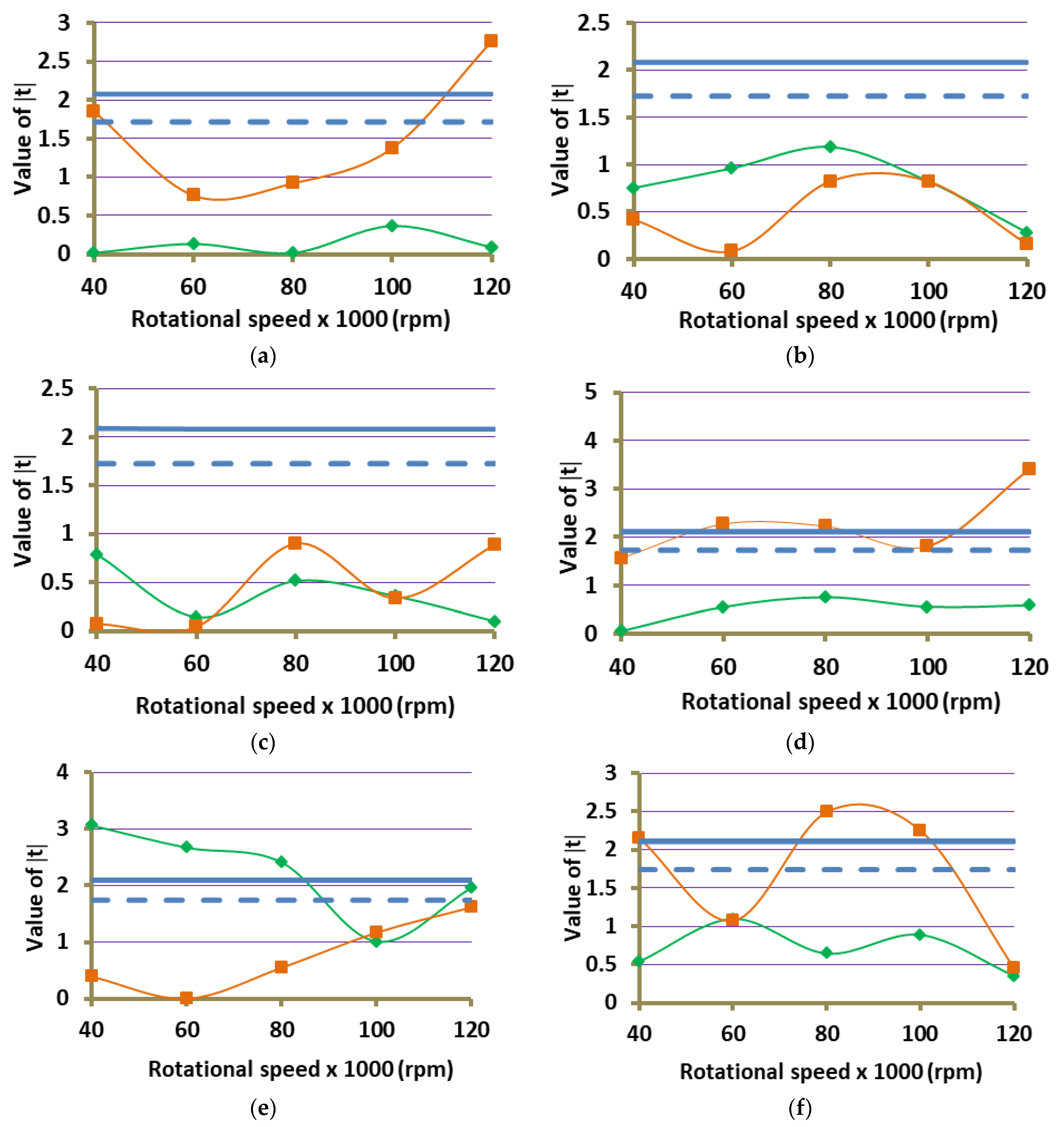
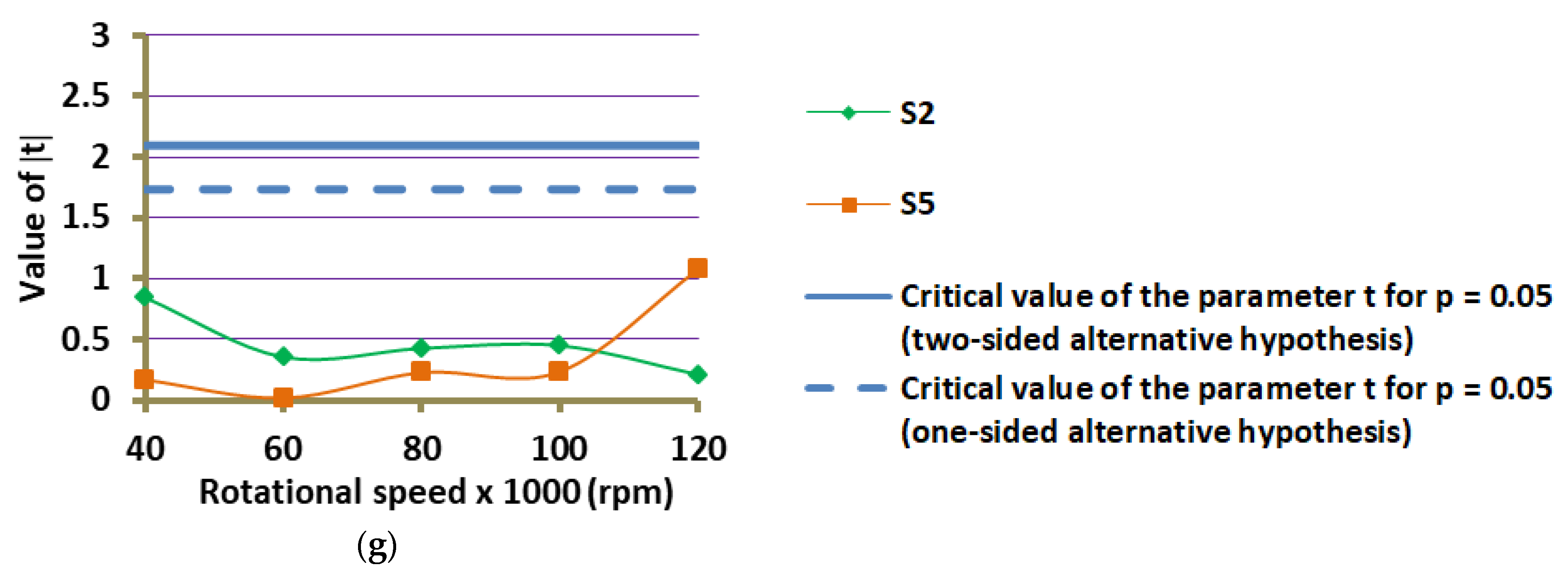
3.3. Statistical Analysis

Changes in the described operating parameters of TG and emissions between the tested, modified fuel mixtures, and DF are relatively small. For example, for the 80k rpm test point, the difference in NOx emissions between DF and S5 is 1.12 ppm, with standard deviations of ±1.25 ppm and ±0.94 ppm for DF and S5, respectively (Figure 11a). In order to check whether the differences obtained from the measurements of operating parameters and emission from TG are statistically significant, the t-Student test was performed for each measured parameter at each of the tested regime.
The similarity of the distribution of data obtained from experimental trials to the normal distribution was tested using the Shapiro–Wilk test. Confirmation of the similarity of the distribution of the obtained data to the normal distribution at the level of significance not lower than p = 0.05 in all cases was obtained. In order to verify the hypothesis of the homogeneity of the variance of the compared data, the Fisher–Snedecor test was used. If the null hypothesis of homogeneity of variance for the compared groups of data was not confirmed, the Cochran-Cox correction was used for the Student’s t-test.
For all analyzed cases, in the Student’s t-test, a null hypothesis was formulated that the mean values of the measured parameters in each of the regimes S2 and S5 come from the population with the same mean as the corresponding parameter in the same regime for the DF case.
H 0 :   µ 1 = µ 2 ,
Three alternative hypotheses were put forward, the choice of which was made individually for each case (Table 4). A two-sided alternative hypothesis was made that the population to be compared cannot come from the population with the same mean as the data from the case of DF (2), as well as two one-sided alternative hypotheses that the compared data have a smaller mean (3) and a larger mean (4) than those recorded during the DF burning in TG.
H 1 :   µ 1 µ 2 ,
H 1 :   µ 1 > µ 2 ,
H 1 :   µ 1 < µ 2 ,
The values of the t parameter obtained as a result of the statistical analysis are presented in Figure 12. The blue horizontal lines mark the critical values of the t parameter at the significance level p = 0.05 [36], for the two-sided alternative hypothesis—by a solid line, and for one-sided alternative hypotheses—by a dashed line. Exceeding the critical value of the parameter t at a given measuring point implies the rejection of the null hypothesis about the equality of means and the adoption of an alternative hypothesis.

4. Discussion of the Results

The addition of 2% emulsifier to the fuel used by the gas turbine (TG) as a standard does not cause a statistically significant change in the unit’s operating parameters. There was also no effect of the use of S2 fuel on emissions, except for CO emissions, which slightly increases (Figure 8). Increasing the amount of emulsifier to 5% resulted in a reduction of the amount of CO emitted to the level of emissions observed during the combustion of standard fuel (DF), at the same time a decrease in NOx emissions was noted. In addition, the use of S5 led to a decrease in the temperature behind the combustion chamber, a statistically significant difference was noted in two out of five regimes (Figure 12a). The addition of 5% emulsifier to the fuel also causes a slight increase in CO2 emissions (Figure 9).
The decrease in NOx emissions due to the use of the S5 fuel mixture (Figure 7) may be caused by the extinction of “hot spots” in the area of the primary combustion zone. Most of the nitrogen oxides produced in a gas turbine are produced according to Zeldovicz’s theory [37,38]. According to this mechanism, NO production takes place at a temperature exceeding 1500 °C and its intensity increases exponentially with increasing temperature [39]. Thus, even a slight reduction in temperature at the hottest points in the reaction area leads to a significant reduction in the production of thermal mono-nitrogen oxides, which play a dominant role in the total NOx emissions from the gas turbine. The effect of extinguishing the “hot spots” in the primary zone of the combustion chamber on the reduction of NOx, in relation to the fuel-water emulsion, was described in [29]. The enrichment of the fuel with an emulsifier may cause analogous changes in the combustion process.
The use of S5 fuel also resulted in a reduction of CO emissions in relation to the emissions recorded for the S2 fuel variant (Figure 8). The emissions dropped to the level at which the TG was powered by the DF. It has been proved in [30] that as a result of lowering the maximum temperature in the primary combustion zone, the intensity of the reaction decreases due to the addition of water to the fuel, which leads to an increase in the volume in the combustion chamber, where the temperature exceeds 1300 K. Mono carbon monoxide oxidizes to CO2 relatively slowly, and this phenomenon is favoured by the temperature exceeding 1270 K [38]. Thus, lowering the maximum temperature in the combustion chamber, leading to the expansion of the reaction zone, extends the residence time of the CO particle in the high temperature region, in which CO oxidation is intensive. The same mechanisms can lead to the simultaneous reduction of CO (relative to S2) and NOx emissions due to the combustion of S5 fuel in the gas turbine, but they occur with a lower intensity.
The use of fuel-water emulsion as a fuel, apart from the simultaneous reduction of CO and NOx emissions, also leads to a reduction of the temperature at the outlet from the combustion chamber [27,29,30]. In the presented studies, for S5 fuel, a statistically significant drop in temperature behind the combustion chamber was recorded only in two out of five measuring points (Figure 12a). However, considering the decrease in NOx emissions recorded at the measuring points 60k, 80k, and 100k rpm, it can be assumed that due to the use of the S5 fuel mixture, the temperature behind the combustion chamber generally slightly drops compared to the case of feeding the turbine with DF fuel in the entire rotational speed range of the turbine. The emission of thermal mono-nitrous oxide depends exponentially on temperature. Thus, a statistically significant decrease in NOx emissions (Figure 7) is caused by the extinction of “hot spots” in the primary combustion zone, which extinction leads to a reduction in the temperature behind the combustion chamber. However, its decrease is so small that it cannot be clearly stated using the described research method that it takes place when the gas turbine operates at a rotational speed of 60k–100k rpm.
The only change, due to the use of S2, in the analyzed operating and emission parameters occurred for the CO emission. The addition of 2% of the emulsifier increased the CO emission, with the simultaneous lack of temperature change behind the combustion chamber and NOx emission. This proves that the emulsifier in this amount, during evaporation, is able to collect too little heat from the environment to reduce the temperature in the reaction zone, or also not being able to completely evaporate in the area of the primary combustion zone. The increase in CO emissions as a result of the use of S2 fuel, as compared to the DF turbine, may be caused, among other things, by the fact that the presence of the emulsifier hinders the access of oxygen to the fuel, which causes the fuel mixture enrichment effect. Moreover, in studies conducted on single drops of emulsion fuel, the combustion phase of the emulsifier is observed, which follows the micro-explosion phenomenon [17,18]. This process is relatively long compared to n-decane combustion, which is due to the low volatility of the emulsifier [17]. Consequently, the emulsifier may not burn completely, leading to increased CO emissions.
It should be added that the experimental studies conducted on the influence of the emulsifier on the combustion process in miniature TG turned out to be very helpful in the context of the interpretation of the results of the research on the combustion process of the fuel-water emulsion in the TG chamber presented in the works [28,29,30], in which this emulsifier was used for creating fuel-water emulsions.

5. Conclusions

Experimental studies were carried out to investigate the effect of the addition of an emulsifier to the fuel on the operating parameters and emissions from the gas turbine. The effect of using 2% addition of emulsifier (S2) and 5% addition of emulsifier (S5) to the fuel with which the gas turbine is supplied as standard (DF) was investigated.
The main results can be summarized as follows:
  • The addition of 2% emulsifier to the fuel used by the gas turbine as standard does not affect thrust-specific fuel consumptions, thrust generated at certain rotational speeds and the temperature behind the combustion chamber. Thus, as a result of enriching the fuel with an emulsifier (2% by mass), the thermal efficiency of the gas turbine does not change.
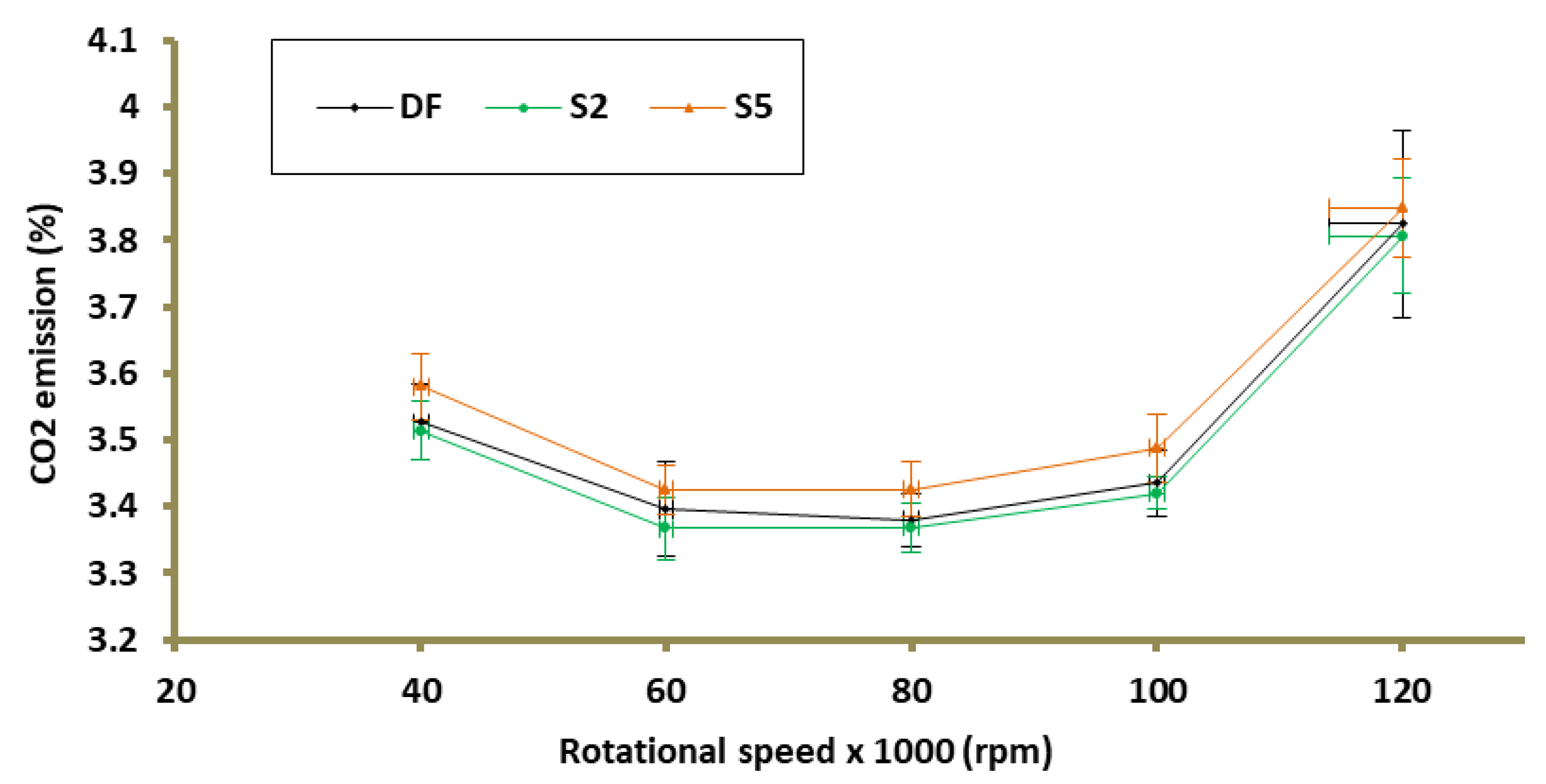
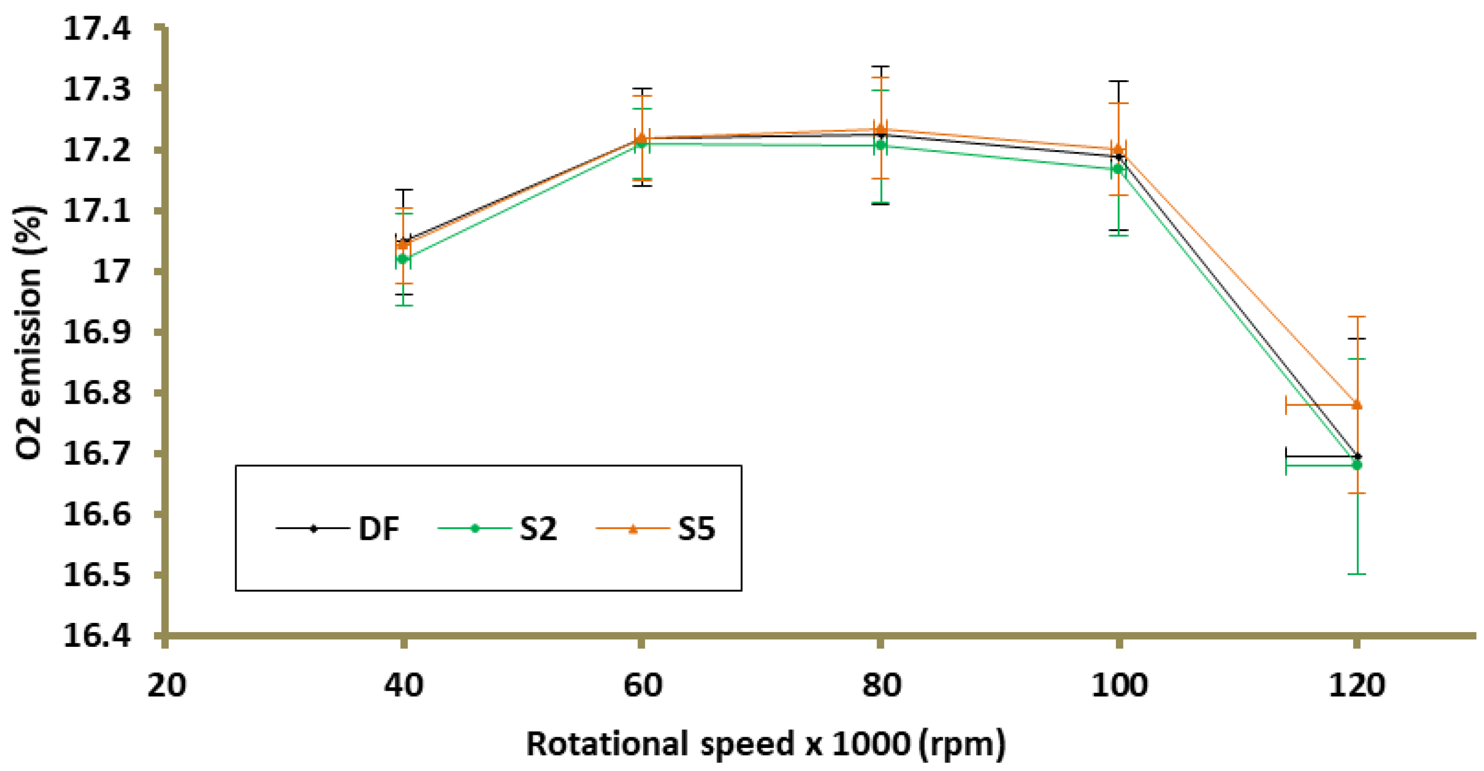
  • The use of S2 fuel mixture has no effect on NOx, CO2, and O2 emissions, but increases CO emissions. The maximum recorded increase was 96.6 ppm, which is 9.1%.
  • The use of the S5 fuel mixture does not change the thrust-specific fuel consumptions and the generated thrust at certain rotational speeds of the turbine in relation to the case in which the TG is supplied with the DF. The addition of 5% emulsifier to the fuel caused a statistically significant drop in the temperature behind the combustion chamber in two of the five measuring points, which, with the remaining operating parameters remaining unchanged, is associated with a reduction in thermal efficiency.
  • Increasing the amount of emulsifier in the fuel from 2% to 5% eliminates the negative impact of the addition of emulsifier on CO emissions, which was noted in the case of S2. In addition, it reduces NOx emissions—a decrease of 8.5% compared to the case in which DF was burned.

Author Contributions

Conceptualization, M.G. and P.N.; methodology, M.G.; software, P.N.; validation, P.N.; formal analysis, P.N.; investigation, P.N.; resources, M.G. and P.N.; data curation, P.N.; writing—original draft preparation, P.N.; writing—review and editing, M.G.; visualization, P.N.; supervision, M.G.; project administration, M.G. and P.N.; funding acquisition, M.G. and P.N. All authors have read and agreed to the published version of the manuscript.

Funding

This research received no external funding.

Institutional Review Board Statement

Not applicable.

Informed Consent Statement

Not applicable.

Data Availability Statement

Not applicable.

Acknowledgments

This research was supported by the Faculty of Power and Aeronautical Engineering, Warsaw University of Technology (equipment and materials used for experiments).

Conflicts of Interest

The authors declare no conflict of interest. The funders had no role in the design of the study; in the collection, analyses, or interpretation of data; in the writing of the manuscript, or in the decision to publish the results.

References

  1. Ardabili, S.F.; Najafi, B.; Aghbashlo, M.; Khounani, Z.; Tabatabaei, M. Performance and emission analysis of a dual-fuel engine operating on high natural gas substitution rates ignited by aqueous carbon nanoparticles-laden diesel/biodiesel emulsions. Fuel 2021, 294, 120246. [Google Scholar] [CrossRef]
  2. Fulara, S.; Chmielewski, M.; Gieras, M. Variable Geometry in Miniature Gas Turbine for Improved Performance and Reduced Environmental Impact. Energies 2020, 13, 5230. [Google Scholar] [CrossRef]
  3. Hosseinzadeh-Bandbafha, H.; Tabatabaei, M.; Aghbashlo, M.; Khanali, M.; Demirbas, A. A comprehensive review on the environmental impacts of diesel/biodiesel additives. Energy Convers. Manag. 2018, 174, 579–614. [Google Scholar] [CrossRef]
  4. Vigneswaran, R.; Annamalai, K.; Dhinesh, B.; Krishnamoorthy, R. Experimental investigation of unmodified diesel engine performance, combustion and emission with multipurpose additive along with water-in-diesel emulsion fuel. Energy Convers. Manag. 2018, 172, 370–380. [Google Scholar] [CrossRef]
  5. Chmielewski, M.; Gieras, M. Impact of variable geometry combustor on performance and emissions from miniature gas turbine engine. J. Energy Inst. 2017, 90, 257–264. [Google Scholar] [CrossRef]
  6. Fulara, S.; Gieras, M.; Chmielewski, M. Miniature gas turbine with variable area nozzle. Arch. Combust. 2017, 37, 127–138. [Google Scholar]
  7. Suchocki, T.; Lampart, P.; Kazimierski, P.; Januszewicz, K.; Gawron, B. Experimental investigation of performance and emission characteristics of a miniature gas turbine supplied by blends of kerosene and waste tyre pyrolysis oil. Energy 2021, 215, 119125. [Google Scholar] [CrossRef]
  8. Sartomo, A.; Santoso, B.; Muraza, O. Recent progress on mixing technology for water-emulsion fuel: A review. Energy Convers. Manag. 2020, 213, 112817. [Google Scholar] [CrossRef]
  9. Mondal, P.K.; Mandal, B.K. Experimental investigation on the combustion, performance and emission characteristics of a diesel engine using water emulsified diesel prepared by ultrasonication. J. Braz. Soc. Mech. Sci. Eng. 2018, 40, 1–17. [Google Scholar] [CrossRef]
  10. Preetika, R.; Mehta, P.S.; Kaisare, N.S.; Basavaraj, M.G. Kinetic stability of surfactant stabilized water-in-diesel emulsion fuels. Fuel 2019, 236, 1415–1422. [Google Scholar] [CrossRef]
  11. Ghannam, M.T.; Selim, M.Y.E. Stability behavior of water-in-diesel fuel emulsion. Pet. Sci. Technol. 2009, 27, 396–411. [Google Scholar] [CrossRef]
  12. Nadeem, M.; Rangkuti, C.; Anuar, K.; Haq, M.R.U.; Tan, I.B.; Shah, S.S. Diesel engine performance and emission evaluation using emulsified fuels stabilized by conventional and gemini surfactants. Fuel 2006, 85, 2111–2119. [Google Scholar] [CrossRef]
  13. Abu-Zaid, M. An experimental study of the evaporation characteristics of emulsified liquid droplets. Heat Mass Transf. 2004, 40, 737–741. [Google Scholar] [CrossRef]
  14. Jeong, I.; Lee, K.H.; Kim, J. Characteristics of auto-ignition and micro-explosion behavior of a single droplet of water-in-fuel. J. Mech. Sci. Technol. 2008, 22, 148–156. [Google Scholar] [CrossRef]
  15. Kadota, T.; Yamasaki, H. Recent advances in the combustion of water fuel emulsion. Prog. Energy Combust. Sci. 2002, 28, 385–404. [Google Scholar] [CrossRef]
  16. Abdollahi, M.; Ghobadian, B.; Najafi, G.; Hoseini, S.S.; Mofijur, M.; Mazlan, M. Impact of water–biodiesel–diesel nano-emulsion fuel on performance parameters and diesel engine emission. Fuel 2020, 280, 118576. [Google Scholar] [CrossRef]
  17. Kim, H.; Baek, S.W. Combustion of a single emulsion fuel droplet in a rapid compression machine. Energy 2016, 106, 422–430. [Google Scholar] [CrossRef]
  18. Gan, Y.; Qiao, L. Combustion characteristics of fuel droplets with addition of nano and micron-sized aluminum particles. Combust. Flame 2011, 158, 354–368. [Google Scholar] [CrossRef]
  19. Kichatov, B.; Korshunov, A.; Kiverin, A.; Son, E. Experimental study of foamed emulsion combustion: Influence of solid microparticles, glycerol and surfactant. Fuel Process. Technol. 2017, 166, 77–85. [Google Scholar] [CrossRef]
  20. Mondal, P.K.; Mandal, B.K. A comprehensive review on the feasibility of using water emulsified diesel as a CI engine fuel. Fuel 2019, 237, 937–960. [Google Scholar] [CrossRef]
  21. Hasannuddin, A.K.; Wira, J.Y.; Srithar, R.; Sarah, S.; Ahmad, M.I.; Aizam, S.A.; Aiman, M.A.B.; Zahari, M.; Watanabe, S.; Azrin, M.A.; et al. Effect of emulsion fuel on engine emissions–A review. Clean Technol. Environ. Policy 2016, 18, 17–32. [Google Scholar] [CrossRef]
  22. Jhalani, A.; Sharma, D.; Soni, S.L.; Sharma, P.K.; Sharma, S. A comprehensive review on water-emulsified diesel fuel: Chemistry, engine performance and exhaust emissions. Environ. Sci. Pollut. Res. 2019, 26, 4570–4587. [Google Scholar] [CrossRef] [PubMed]
  23. Yahaya Khan, M.; Abdul Karim, Z.A.; Hagos, F.Y.; Aziz, A.R.A.; Tan, I.M. Current trends in water-in-diesel emulsion as a fuel. Sci. World J. 2014, 2014, 527472. [Google Scholar] [CrossRef]
  24. Gopidesi, R.K.; Rajaram, P.S. A review on emulsified fuels and their application in diesel engine. Int. J. Ambient. Energy 2019, 1–9. [Google Scholar] [CrossRef]
  25. Zhang, Z.; Gollahalli, S.R. Combustion of Kerosene-Water Emulsions in a Gas Turbine Combustor. In Turbo Expo: Power for Land, Sea, and Air; American Society of Mechanical Engineers: New York, NY, USA, 1985; Volume 79436, p. V002T04A030. [Google Scholar] [CrossRef]
  26. Moses, C.A.; Coon, C.W.; Altavilla, P.A. Reduction of Exhaust Smoke from Gas-Turbine Engines by Using Fuel Emulsions; Army Fuels and Lubricants Research Lab, Southwest Research Inst: San Antonio, TX, USA, 1980. [Google Scholar]
  27. De Giorgi, M.G.; Fontanarosa, D.; Ficarella, A.; Pescini, E. Effects on performance, combustion and pollutants of water emulsified fuel in an aeroengine combustor. Appl. Energy 2020, 260, 114263. [Google Scholar] [CrossRef]
  28. Chmielewski, M.; Gieras, M.; Niszczota, P. Fuel-Water emulsion impact on miniature gas turbine pollutant emission. In Proceedings of the XIV Research & Development in Power Engineering, E3S Web of Conferences, Warsaw, Poland, 3–6 December 2019. [Google Scholar] [CrossRef] [Green Version]
  29. Chmielewski, M.; Niszczota, P.; Gieras, M. Combustion efficiency of fuel-water emulsion in a small gas turbine. Energy 2020, 211, 118961. [Google Scholar] [CrossRef]
  30. Niszczota, P.; Gieras, M. Impact of the Application of Fuel and Water Emulsion on CO and NOx Emission and Fuel Consumption in a Miniature Gas Turbine. Energies 2021, 14, 2224. [Google Scholar] [CrossRef]
  31. Chmielewski, M.; Gieras, M. Study of combustion efficiency and pollutant emissions in a miniature gas turbine with the combustion chamber of variable geometry. Rynek Energii 2015, 4, 103–109. [Google Scholar]
  32. Gieras, M. Miniaturowe Silniki Turboodrzutowe, 1st ed.; Oficyna Wydawnicza Politechniki Warszawskiej: Warsaw, Poland, 2016; pp. 29–51. ISBN 978-83-7814-552-3. [Google Scholar]
  33. PCC, SE. Available online: https://www.pcc.eu/ (accessed on 8 July 2021).
  34. Chmielewski, M.; Gieras, M. Small gas turbine GTM-120 bench testing with emission measurements. J. KONES 2015, 22, 47–54. [Google Scholar] [CrossRef]
  35. Gawron, B.; Białecki, T.; Janicka, A.; Suchocki, T. Combustion and Emissions Characteristics of the Turbine Engine Fueled with HEFA Blends from Different Feedstocks. Energies 2020, 13, 1277. [Google Scholar] [CrossRef] [Green Version]
  36. Volk, W. Statystyka Stosowana dla Inżynierów, 1st ed.; Wyd. Nauk. Techn.: Warsaw, Poland, 1973. [Google Scholar]
  37. Park, J.; Nguyen, T.H.; Joung, D.; Huh, K.Y.; Lee, M.C. Prediction of NO x and CO emissions from an industrial lean-premixed gas turbine combustor using a chemical reactor network model. Energy Fuels 2013, 27, 1643–1651. [Google Scholar] [CrossRef]
  38. Łapucha, R. Komory Spalania Silników Turbinowo-Odrzutowych: Procesy, Obliczenia, Badania; Wydawnictwa Naukowe Instytutu Lotnictwa: Warsaw, Poland, 2004; pp. 117–152. ISBN 83-915995-8-2. [Google Scholar]
  39. Gieras, M. Komory Spalania Silników Turbinowych: Organizacja Procesu Spalania, 1st ed.; Oficyna Wydawnicza Politechniki Warszawskiej: Warsaw, Poland, 2010; pp. 120–122. ISBN 978-83-7207-864-3. [Google Scholar]
Figure 1. GTM-120 gas turbine test stand: (a) GTM-120 gas turbine; (b) gas fuel tank; (c) liquide fuel tank; (d) exhaust gas analyzer.
Energies 14 05255 g001
Figure 2. Fuel mixture ingredients; (a) emulsifier, (b) microscopic photo S2; (c) fuel-water emulsion; (d) microscopic photograph of a fuel-water emulsion. Scale bar corresponds to 50 µm.
Energies 14 05255 g002
Figure 3. Temperature behind the combustion chamber as a function of engine rotational speed.
Energies 14 05255 g003
Figure 4. Turbine thrust as a function of rotational speed.
Energies 14 05255 g004
Figure 5. Thrust-specific fuel consumptions as a function of rotational speed.
Energies 14 05255 g005
Figure 6. Gas turbine operating parameters at 80k rpm; (a) temperature behind the combustion chamber, (b) thrust, (c) thrust-specific fuel consumptions.
Energies 14 05255 g006
Figure 7. NOx emission depending on the rotational speed.
Energies 14 05255 g007
Figure 8. CO emission depending on the rotational speed.
Energies 14 05255 g008
Figure 9. CO2 emission as a function of rotational speed.
Energies 14 05255 g009
Figure 10. O2 emission as a function of rotational speed.
Energies 14 05255 g010
Figure 11. Gas turbine emission at 80k rpm; (a) NOx, (b) CO, (c) CO2, (d) O2.
Energies 14 05255 g011
Figure 12. The value of the parameter t as a function of the rotational speed of the gas turbine for; (a) temperatures downstream of the combustion chamber, (b) thrust, (c) thrust-specific fuel consumptions, (d) NOx, (e) CO, (f) CO2, (g) O2.
Energies 14 05255 g012aEnergies 14 05255 g012b
Table 1. Parameters of the sensors used to measure the emissions.
MeasurementSensor TypeResolutionAccuracy
O 2 electrochemical0.01 vol.% ± 0.8 % of fsv
COelectrochemical1 ppm ± 5 %   measured value
CO 2 infrared 0.01   vol .   CO 2 ± 0.3   vol .   CO 2 + 1 %   measured value
NOelectrochemical0.1 ppm ± 2   ppm
  NO 2 electrochemical0.1 ppm ± 5   ppm
Table 2. Percentage mass fraction of components in fuel blends.
Fuel MixtureJet A-1OilSurfactant
DF95.00 5.00 0
S293.10 4.902
S590.25 4.755
Table 3. Percentage mass fraction of components in the emulsifier.
Surfactant Ingredients
Rokwin 8050.00
Rokanol RZ4P1125.00
Rokanol DB322.50
Rokafenol N81.67
Water0.83
Table 4. Adopted alternative hypothesis.
T4 *F **TSFCNOxCOCO2O2
S2(2)(2)(2)(2)(4)(2)(2)
S5(3)(2)(2)(3)(2)(4)(2)
* Temperature after the combustion chamber, ** Engine thrust.
Publisher’s Note: MDPI stays neutral with regard to jurisdictional claims in published maps and institutional affiliations.

