Article

A Coordinated Optimal Strategy for Voltage and Reactive Power Control with Adaptive Amplitude Limiter Based on Flexible Excitation System

1
Department of Power Engineering, School of Electric Science and Engineering, Huazhong University of Science and Technology, Wuhan 430073, China
2
Department of Power Grid Technology, State Grid Zhejiang Electric Power Research Institute, Hangzhou 310007, China
*
Author to whom correspondence should be addressed.
Energies 2021, 14(16), 5212; https://doi.org/10.3390/en14165212
Submission received: 28 June 2021 / Revised: 12 August 2021 / Accepted: 14 August 2021 / Published: 23 August 2021

Abstract

:
The flexible excitation system (FES) is a kind of novel excitation system with two channels for damping control. Besides the basic functions of traditional excitation systems, flexible excitation systems can provide reactive power support for the terminal voltage, and the large-capacity FES can improve the voltage stability and power-angle stability of synchronous generator units. However, with the increase in system capacity and the complication of control objectives, the difficulty of controller design will be increased. The randomness and fluctuation of new energy resources such as photovoltaic and wind turbines may cause disturbance and fault to the power system, which requires the coordinated control strategy for the FES to achieve stability in voltage and power angle. In this paper, the basic characteristics of FES are analyzed, and the mathematic model of the single machine infinite bus (SMIB) system based on FES is derived. The coordinated control strategy based on decoupling control of stator and rotor is proposed according to the optimal objectives of voltage stability and power-angle stability, and the linear optimal excitation control (LOEC) is adopted with the adaptive amplitude limiter (AAL) determined by fuzzy rules. The MATLAB/Simulink platform is established and the results verify the superiority of the proposed LOEC + AAL control strategy in large disturbance working conditions, which showed better robustness. The proposed coordinated control strategy provides an effective solution for industrial application and performance improvement of FES.

1. Introduction

The power system in China is one of the largest in the world. With the changes in the structure of the energy resources in recent years, several problems have received attention, including the low-frequency oscillation, the voltage fluctuation, and the deficiency of reactive power support, because of the wide application of distributed power generations such as photovoltaic and wind turbine [1,2,3,4,5,6]. The changes in the future energy structure will challenge the voltage and reactive power stability of the power grid.
Reactive power compensation is one of the most important methods for power system stability; traditional reactive power compensation devices include capacitors, generator excitation systems, and the static synchronous compensator (STATCOM), etc. The synchronous generator can provide active power to the grid; as for reactive power support, high-power excitation systems, which are considered the most important reactive power compensation devices, are required for large-capacity synchronous generators to meet the demands of stability and rapidity in disturbance conditions. The traditional excitation system adopts the silicon control rectifier (SCR), which is a kind of half-controlled power device. The automatic voltage regulator (AVR) and power system stabilizer (PSS) are used in conventional strategies to achieve voltage stability and suppress the power-angle oscillation [7]. Linear optimal excitation control is another classical strategy for power system stability, which has similar effects to AVR + PSS and is easy to be realized [8].
In order to improve the comprehensive property of excitation systems, the flexible excitation system (FES), which is a kind of novel excitation system adopting full-controlled electronic devices, is proposed in [9,10]. Reference [11] investigates the strategy for intensive excitation using FES; the optimization in DC-link capacitor voltage is realized to improve the field voltage in large disturbance conditions. Reference [12] investigates the optimal strategies for PSS parameter setting; the particle swarm optimization (PSO) algorithm is applied in the off-line controller, and the industrial prototype is built for field tests. However, the off-line optimized parameters may not be perfectly suitable for all conditions as the power system is considered a nonlinear mathematical model; so, the reference [13] considers the nonlinearity of single machine infinite bus (SMIB) systems and proposes the nonlinear optimal excitation control strategy (NOEC), which can further improve the damping control effects in large-disturbance conditions. However, the difficulty of modeling and designing for FES controllers is much increased in the NOEC compared to the LOEC, so there are still problems that should be deeply discussed in the robust controller design. As the first engineering operation of FES was finished in Wenzhou, Zhejiang Province, China on 1 December 2020, a coordinated control system aiming at both the voltage and power-angle stability is required for improving the performance.
Considering these points, a coordinated optimal strategy for voltage and reactive power control based on the flexible excitation system was proposed to achieve optimization in different disturbance conditions and reduce difficulties in engineering realization. An adaptive amplitude limiter was proposed to improve the stability during the transient process. The mathematical model of the optimal control problem is derived in Section 2. The coordinated optimal strategy is designed in Section 3 according to the degree of disturbances; the method of adaptive LOEC control, and fuzzy logic control were used. The simulation results were obtained in Section 4, and prove the effectiveness of the proposed strategy in voltage and power-angle stability, compared with the traditional LOEC controller. Section 5 concludes this paper.

2. Mathematical Model

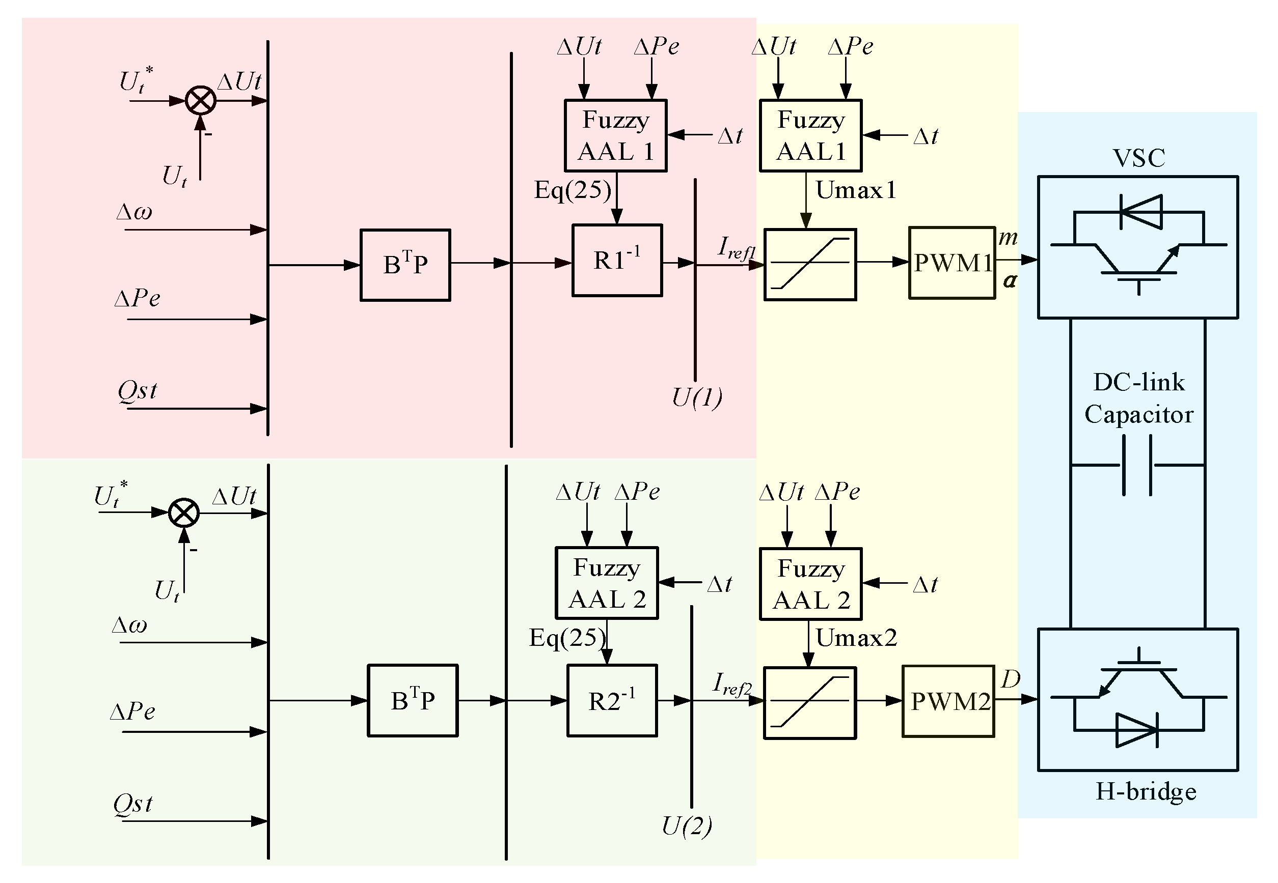
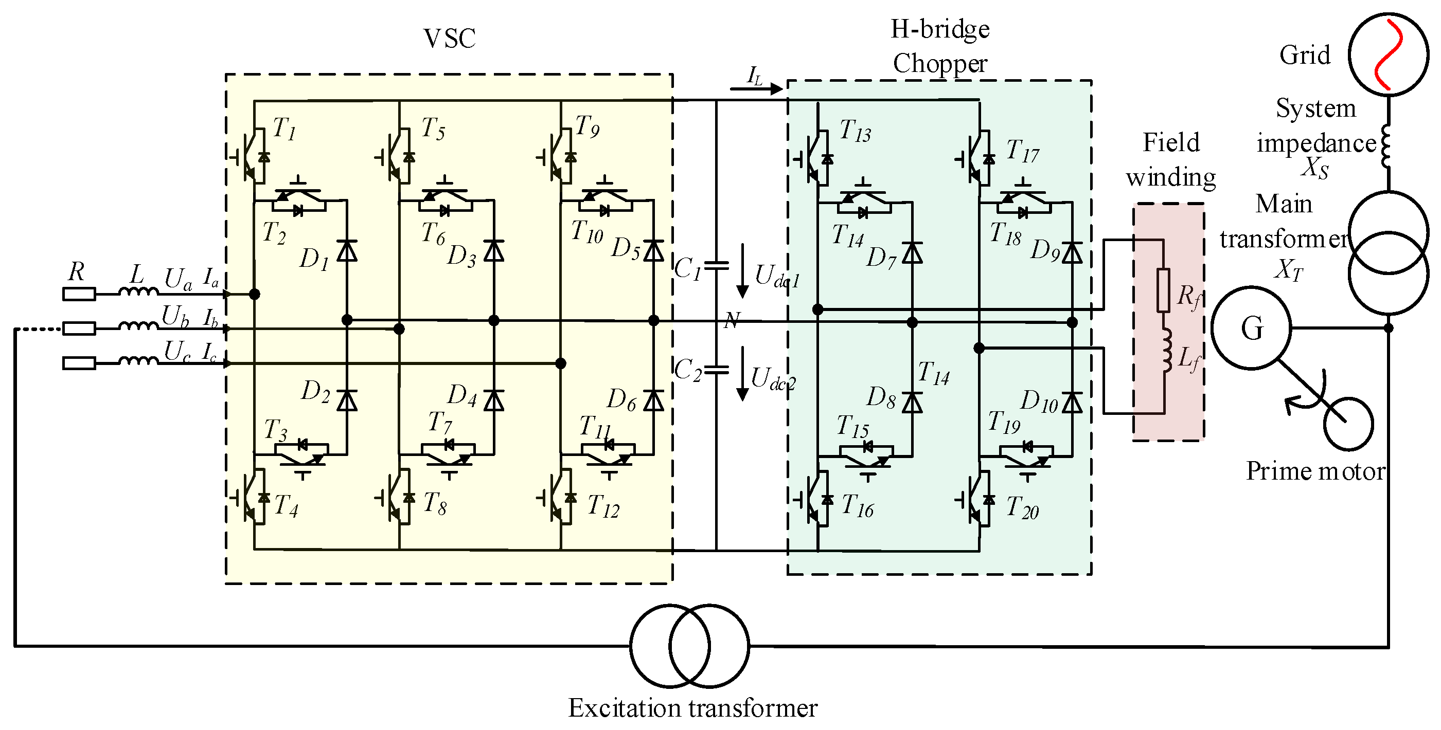
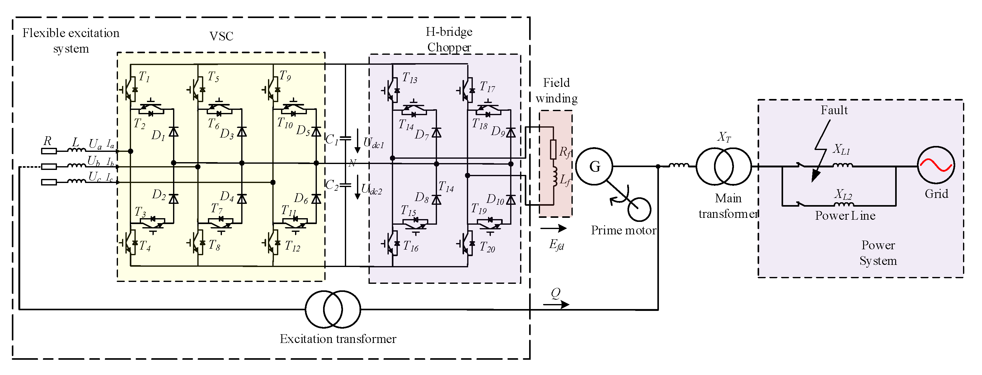
2.1. Mathematical Model of FES

As shown in Figure 1, the physical structure of the FES in this paper consisted of the voltage source converter (VSC), the DC-link capacitor, and the H-bridge chopper. The three-level topology was adopted, which applied to the units with high voltage and large capacity. Compared with the two-level converters, the number of switching tubes was increased in the three-level topology, but the voltage in each single switching tube was reduced, so it had superiority in security and cost. For the VSC, the mathematical model is shown in Equation (1):
{ E a = L d I a d t + R I a + 1 3 ( 2 S 1 a S 1 b S 1 c ) u d c 1 + 1 3 ( 2 S 2 a + S 2 b + S 2 c ) u d c 2 E b = L d I b d t + R I b + 1 3 ( 2 S 1 b S 1 a S 1 c ) u d c 1 + 1 3 ( 2 S 2 b + S 2 a + S 2 c ) u d c 2 E c = L d I c d t + R I c + 1 3 ( 2 S 1 c S 1 b S 1 a ) u d c 1 + 1 3 ( 2 S 2 c + S 2 b + S 2 a ) u d c 2 C 1 d u d c 1 d t = S 1 a I a + S 1 b I b + S 1 c I c i L C 2 d u d c 2 d t = S 2 a I a + S 2 b I b + S 2 c I c i L
where the S is the switching function. S = 1 means the upper bridge arm is in the condition mode, otherwise, it is turned off. While the FES transmits reactive power to the terminal, the voltage can be adjusted by changing the control angle, as shown in Equation (2):
Q δ 57.3 3 U S 2 R = U S 2 19.1 R δ
where Q is the reactive power injection, and Δ is the power angle. For the H-bridge, the field winding has three operation modes of 0.5Udc, 0, and −0.5Udc in the half-voltage chopping condition, while in the full-voltage chopping condition, the three operation modes are −Udc, 0, and Udc for intensive excitation. The field voltage is shown in Equation (3) [14]:
U fd = T P T N T swich u dc = ( 2 D Ch 1 ) u dc
where Ufd is the field voltage, TP is the conduction time of IGBT5 and IGBT8, TN is the conduction time of IGBT6 and IGBT7, Tswitch is the switching period, and DCh is the duty ratio of the PWM trigger pulse.

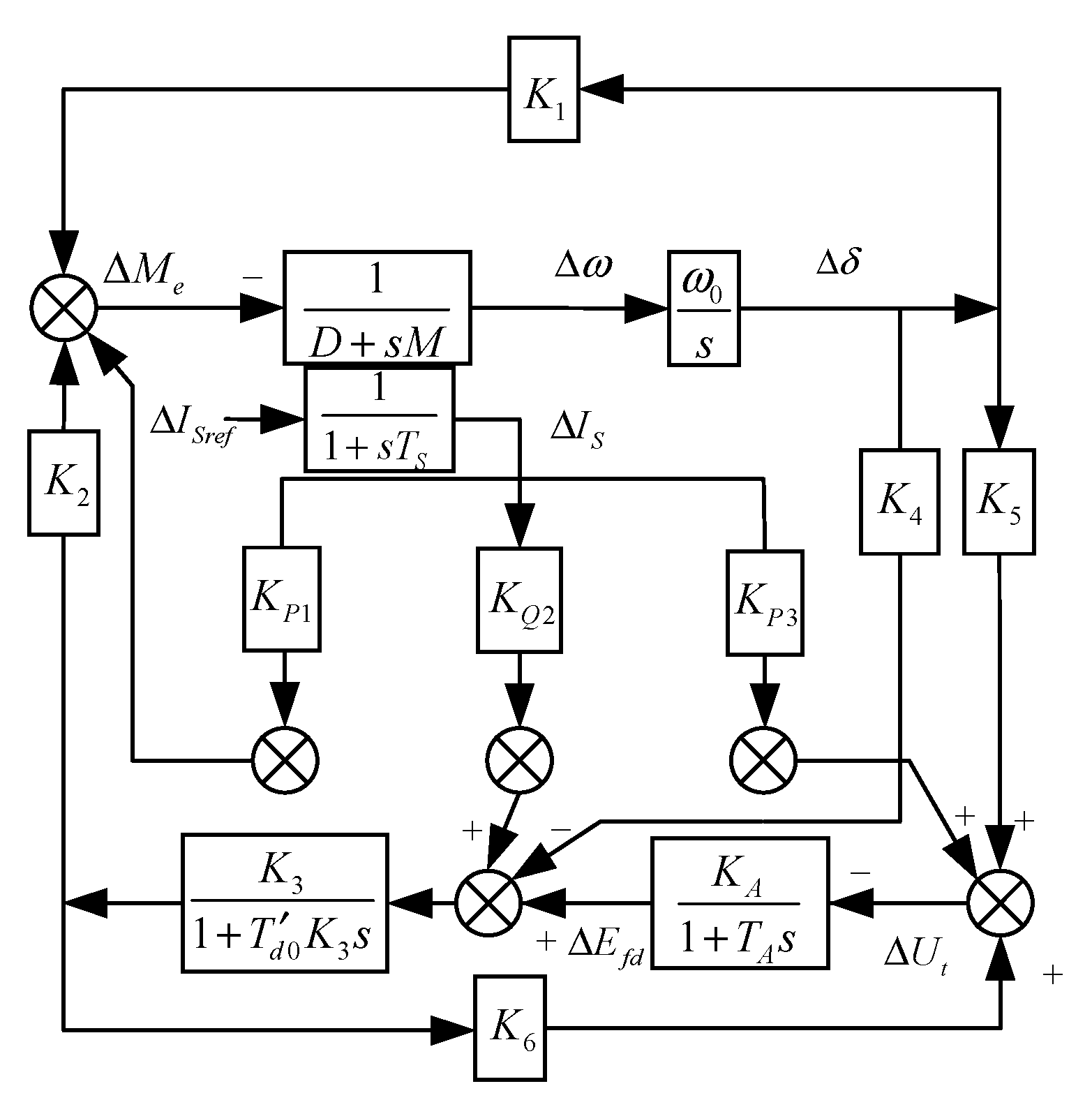
2.2. Mathematical Model of LOEC Control

The major issue in coordinated optimal control is represented by the differences in the inertia time constants because the inertia time constant of the VSC is much lower than the field winding, which is often ignored in other research. In this paper, the state model can be described in Equations (4)–(7):
Δ δ ˙ = ω 0 Δ ω
Δ ω ˙ = ( Δ P e D Δ ω ) / M
Δ E ˙ q = ( Δ E f d Δ E q ) / T d 0
Δ I ˙ S = 1 T Δ I S + 1 T Δ I S r e f
where ω is the rotate speed of the synchronous generator, Eq is the q-axis voltage, IS represents the reactive current of the VSC, T′d0 is the d-axis transient time constant of the synchronous generator, and the Equations (8)–(10) can be obtained:
Δ P e = K 1 Δ δ + K 2 Δ E q + K 10 Δ I S
Δ E q = K 3 1 + T d 0 K 3 s ( Δ E f d K 4 Δ δ + K 11 Δ I S )
Δ U t = K 5 Δ δ + K 6 Δ E q + K 12 Δ I S
Thus, the state model is transformed into:
[ Δ δ ˙ Δ ω ˙ Δ E ˙ q Δ I ˙ S ] = [ 0 ω 0 0 0 K 1 M D M K 2 M K 10 M K 4 T d 0 0 1 T d 0 K 3 K 11 T d 0 0 0 0 1 T S ] [ Δ δ Δ ω Δ E q Δ I S ] + [ 0 0 0 0 1 T d 0 0 0 1 T S ] [ Δ E f d Δ I S r e f ]
where the parameters K1 to K5, and K6 to K10 are [15]:
K 1 = ( x q x d ) i q 0 V b sin δ 0 x d + E Q 0 V b cos δ 0 x q
K 2 = i q 0 x q x d
K 3 = x d x d
K 4 = ( x d x d ) V b sin δ 0 x d
K 5 = U t d 0 x q V b cos δ 0 x q U t 0 U t q 0 x d V b sin δ 0 x d U t 0
K 6 = U t q 0 x S x d U t 0
K 10 = x S U t 0 2 x d x d E q 0 V b sin δ 0 x d x S U t 0 2 V b 2 2 ( x q x d ) x d x q ( x d x d + x q x q ) sin 2 δ 0
K 11 = ( x d x d ) x S U t q 0 x d U t 0 2
K 12 = x S V t 0 3 ( x q U t d 0 2 x q + x d U t q 0 2 x d )
Considering the time constant of the VSC, the Philips–Heffron model is shown in Figure 2.
According to Equation (21):
[ Δ P e Δ ω Δ U t Δ I S ] = [ K 1 0 K 2 K 10 0 1 0 0 K 5 0 K 6 K 12 0 0 0 1 ] [ Δ δ Δ ω Δ E q Δ I S ] + [ 0 0 0 0 0 0 0 0 ] [ Δ E f d Δ I S r e f ]
where the Pe is the electromagnetic power of the synchronous generator that can be represented by active power Peo, so the Equation (21) can be reorganized into the new form: z = T 1 x + T 2 u , z 1 = z T 2 u = z = T 1 x , z ˙ 1 = z ˙ = T 1 x ˙ .
The Riccati equation can be obtained in Equation (22):
P A ¯ + A T ¯ P P B ¯ R 1 B T ¯ P = Q ¯
where: A ¯ = T 1 A T 1 1 , B ¯ = T 1 B , Q ¯ = ( T 1 1 ) T Q T 1 1 .
Thus, the optimal coordinated controller is: u = ( I K ¯ T u ) 1 K ¯ z .
As shown in Equation (23):
[ Δ E f d Δ I S r e f ] = [ k E p k E ω k E U k E S k I p k I ω k I U k I S ] [ Δ P e Δ ω Δ U t Δ I S ]
In summary, the control variables were the field voltage ΔEfd and the reference reactive current ΔISref, which are determined by the electromagnetic power ΔPe, the rotate speed ω, the terminal voltage ΔUt, and the VSC current ΔIS.

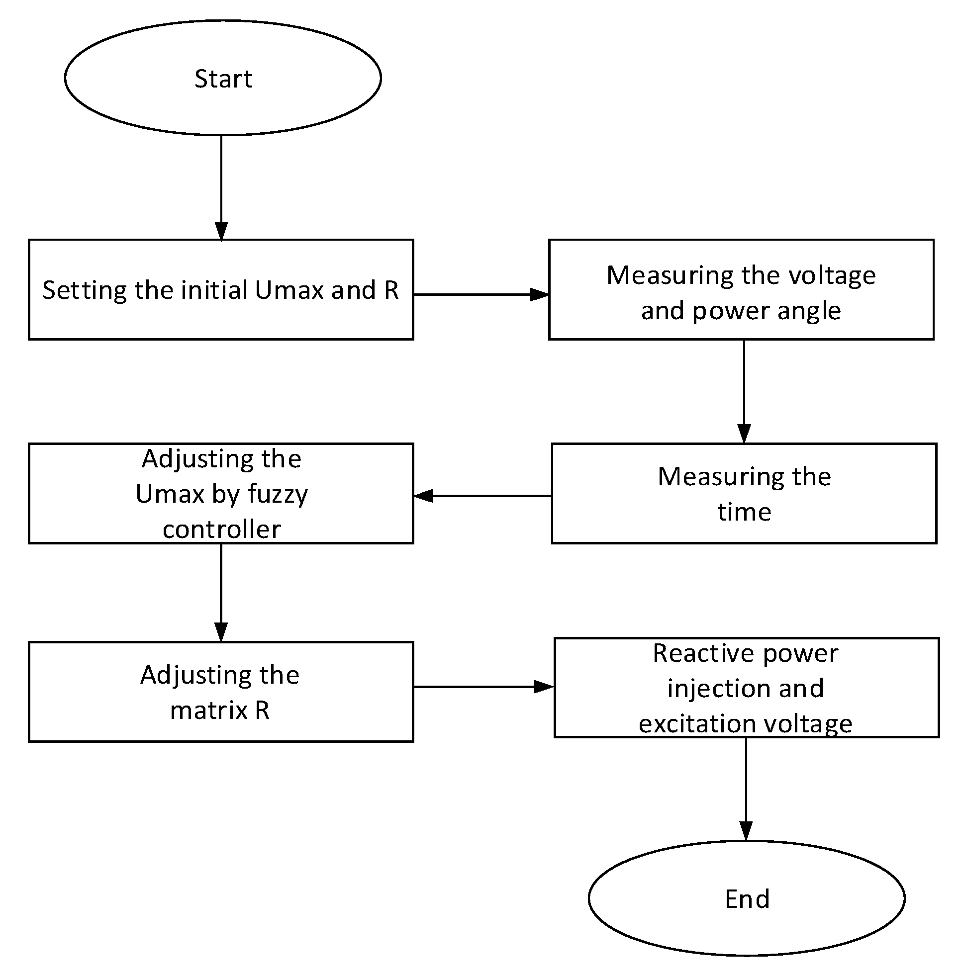
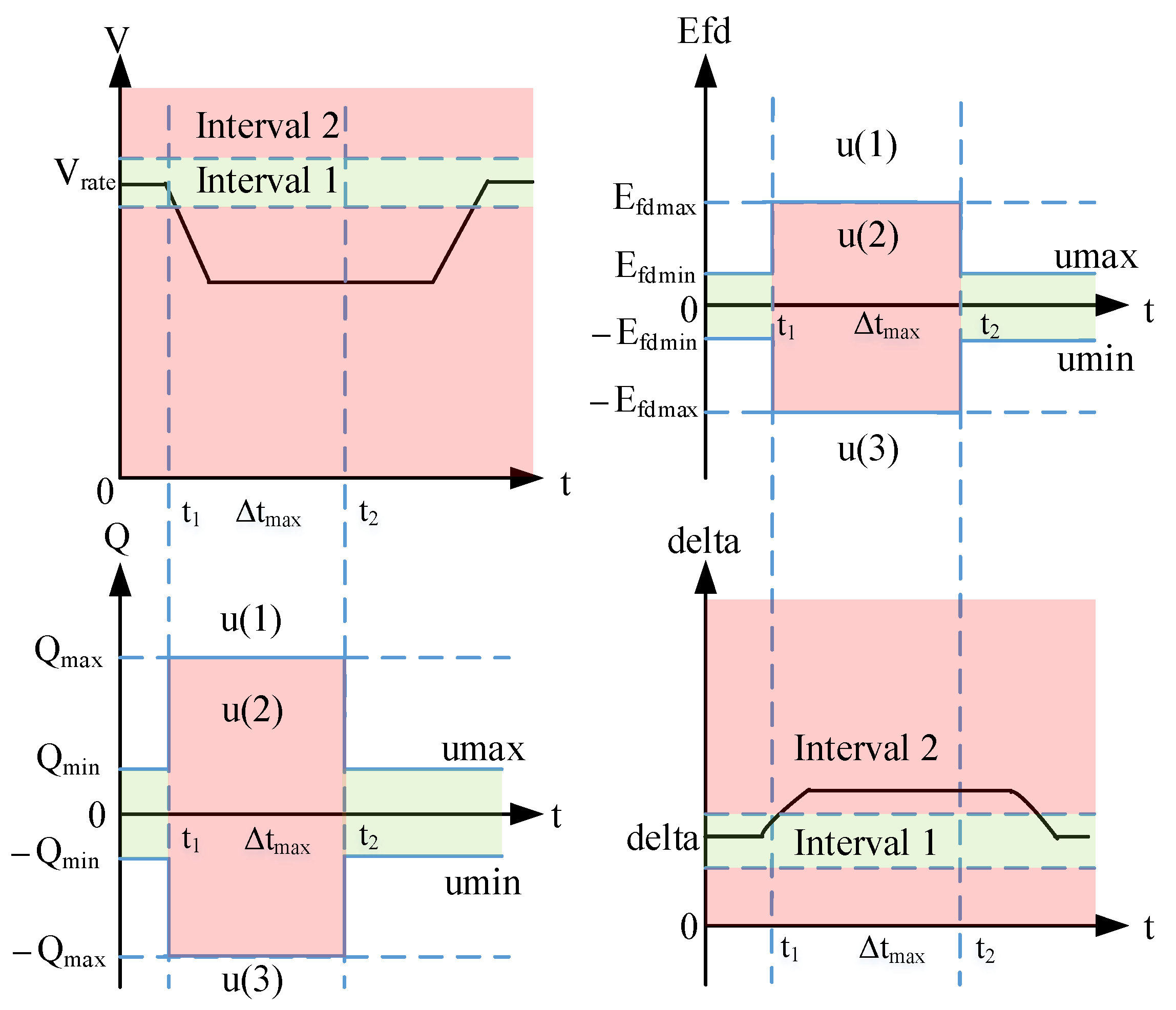
3. The Adaptive LOEC with Amplitude Limiter

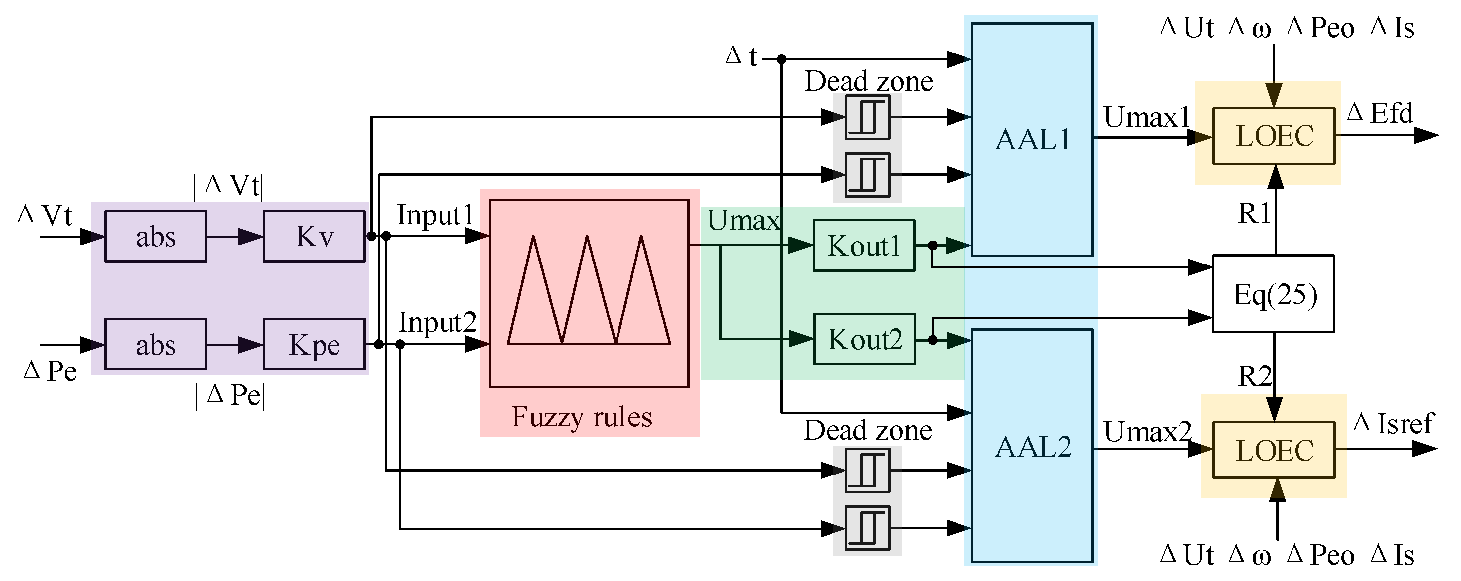
3.1. The Adaptive LOEC

The adaptive LOEC strategy of the VSC was achieved by controlling the weight matrix R (or weight matrix Q) in real-time. According to Equation (24), where the P(t) is obtained by calculating the Ricatti function in Equation (22), R(t) is a diagonal matrix:
u = R 1 ( t ) B T _ ( t ) P ( t ) x * ( t )
According to Equation (25), the variation of R is determined by the limiter Umax. So, the element value of R will be smaller while the limiter is unlocked and the Umax becomes larger:
R = 1 U max k R 0
where k is a constant coefficient and usually k = 1. In this case, the conventional linear-quadratic optimal controller cannot explain the phenomenon of limited control. R0 is the initial value of R.
According to the minimum principle:
H [ x , u , λ ] = 1 2 [ x T ( t ) Q ( t ) x ( t ) + u T ( t ) R ( t ) u ( t ) ] + λ T ( t ) [ A ( t ) x ( t ) + B ( t ) u ( t ) ]
Where the quadratic matrix Q and R is obtained by pole assignment, H is the Hamiltonian function, the adjoint equations are:
λ ˙ ( t ) = d H d x = Q ( t ) x ( t ) A T ( t ) λ ( t ) x ˙ ( t ) = d H d λ = A ( t ) x ( t ) + B ( t ) u ( t ) = A ( t ) x ( t ) B ( t ) R 1 ( t ) B T ( t ) λ ( t )
So, the minimum principle is to realize the minimization of Hamiltonian function:
H [ x * , λ * , u * , t ] = min u U H [ x * , λ * , u , t ]

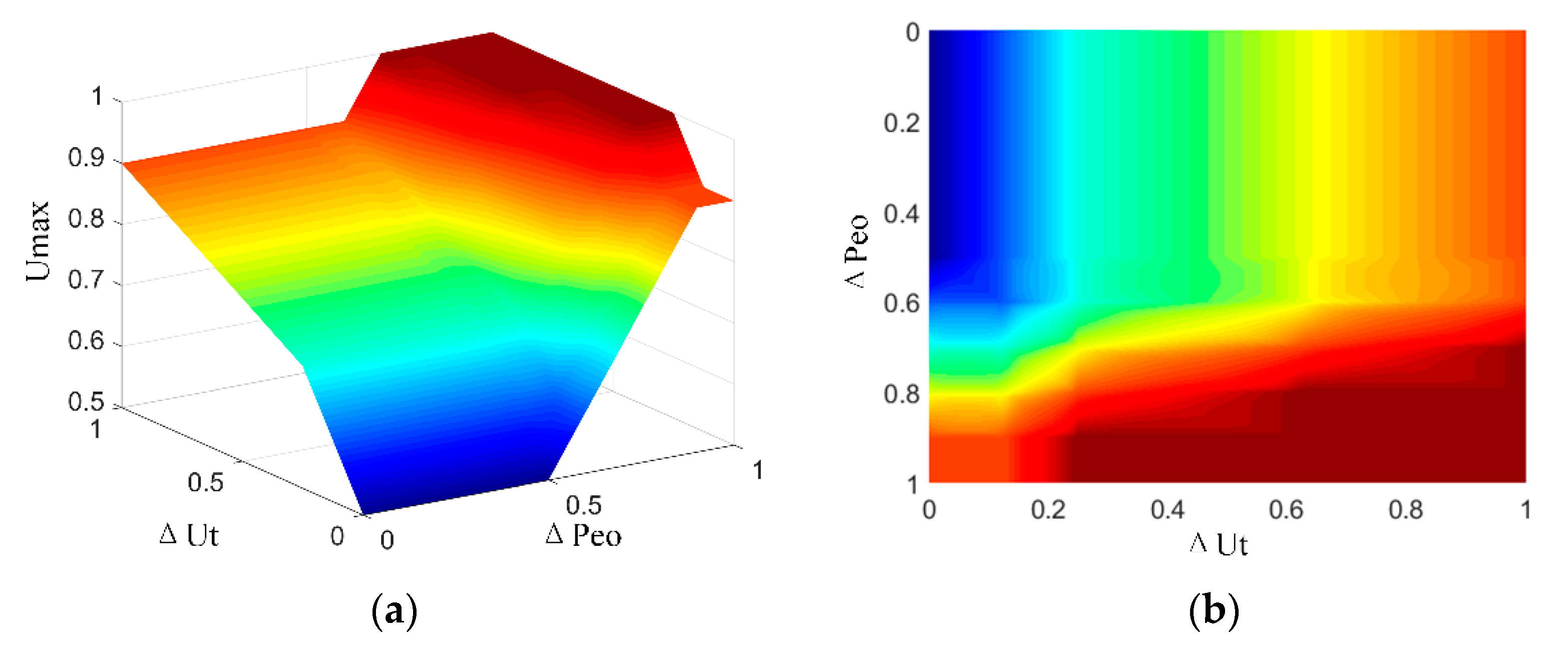
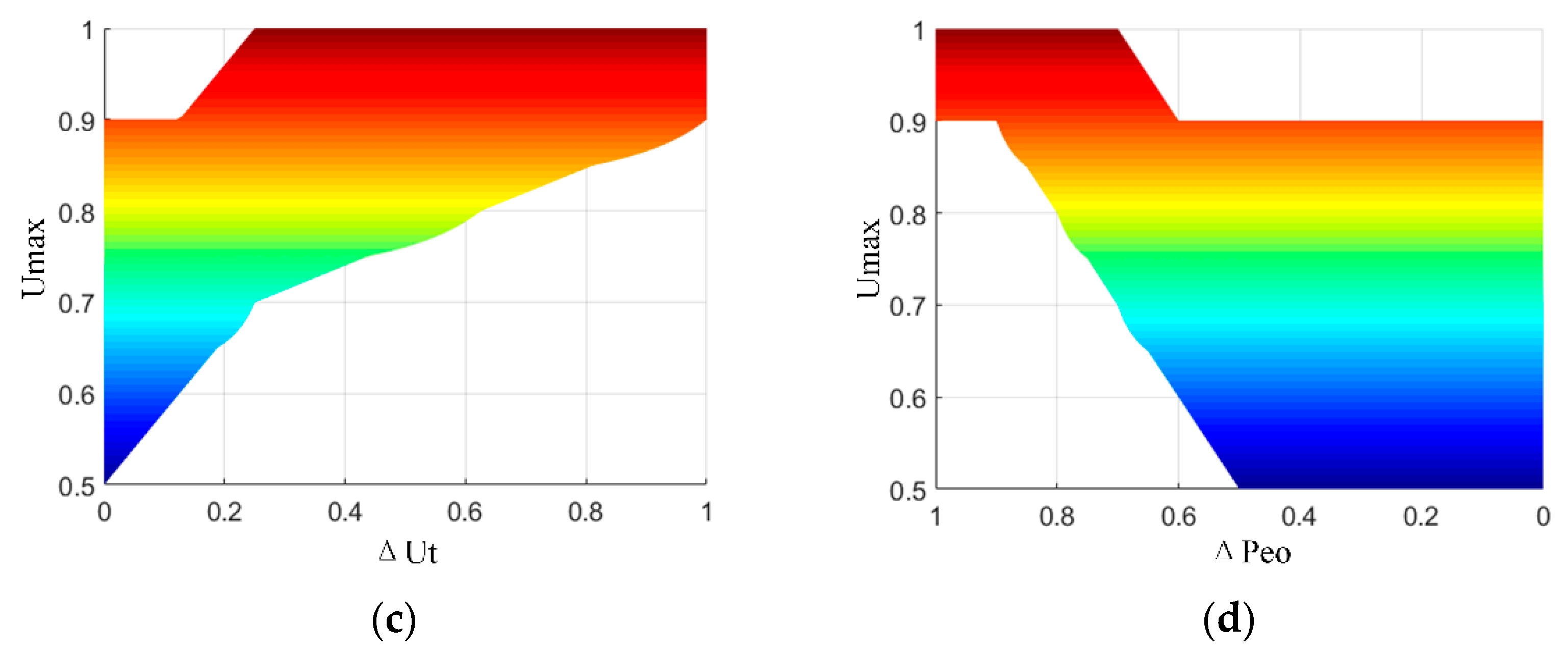
3.2. The Amplitude Limiter

The amplitude limiter was unlocked, determined by Equations (29) and (30):
Δ t < Δ t max Δ P e o < Δ P e o max Δ V t < Δ V max
u ( 1 ) = U max u ( 2 ) = R 1 ( t ) B T ( t ) P ( t ) x * ( t ) u ( 3 ) = U min
where the Δt is the time of voltage instability. ΔPeo is the deviation of active power Peo, ΔVt represents the deviation of terminal voltage, and u(2) represents the control variables Efd and Q within the interval determined by Umax and Umin.
Where the mode selection from u(1) to u(3) are determined by Figure 3. When the voltage instability or power-angle instability occurs, the system state is definitive and the control variables u can be selected by Equation (30).

3.3. The Fuzzy Controller

The fuzzy controller for amplitude limiter was designed in Table 1 and Figure 4, according to the fuzzy rules and fuzzy relationship function [16], where MN (Min), L (Low), SL (Small low), M (Middle), SH (Small high), H (High), and MX (Max) are the rules for determining the values of inputs and the output. The inputs of the fuzzy controller were active power deviation ΔPeo and the voltage deviation ΔUt, and the output was the limit value Umax. While the system instability occurs, the voltage deviation ΔUt and active power deviation ΔPe determined the limiter output Umax according to Equation (25), and the variation of the weight matrix R was determined at the same time.
To avoid frequent mode switching between interval 1 and interval 2, the dead zone was designed in Equation (31). Where Switch is the signal for mode switching, while Switch = 0, the LOEC + AAL was adopted, otherwise the mode was LOEC. In Equation (31), ΔPe0 > ΔPe1 and ΔVt0 > ΔVt1: the Schmitt trigger.
S w i t c h ( P e ) = { 0 Δ P e > P e 0 1 Δ P e < P e 1 } S w i t c h ( V t ) = { 0 Δ V t > Δ V t 0 1 Δ V t < Δ V t 1 } S w i t c h ( t ) = { 0 Δ t > t 0 1 Δ t < t 0 } S w i t c h = S w i t c h ( P e ) & S w i t c h ( V t ) & S w i t c h ( t )
The topology of FES and the structure of the coordinated controller used the LOEC in the small disturbance interval (the interval 1), and adopted the fuzzy controller to adaptively adjust the weight matrix and the limiter output when the large disturbance occurs, as shown in Figure 5, where the Ut* is the reference value of the terminal voltage. The control diagram of the proposed strategy is shown in Figure 6. The control system adopted two fuzzy controllers to give the limiter output Umax1 and Umax2, and these fuzzy controllers could also be incorporated if the fuzzy rules were the same, for simplicity.

4. Simulation Verification

4.1. The Simulation Platform

A simulation model was built under the MATLAB/SIMULINK. The structure of the simulation platform is shown in Figure 7, and the coordinated control system was established according to Figure 5. The structure of the LOEC + AAL controller in the simulation platform is shown in Figure 8, which used the same fuzzy rules and input quantization factors Kpe/Kv in two fuzzy controllers for simplification; the output quantization factors Kout1/Kout2 were different. The parameters of SMIB system are shown in Table 2.

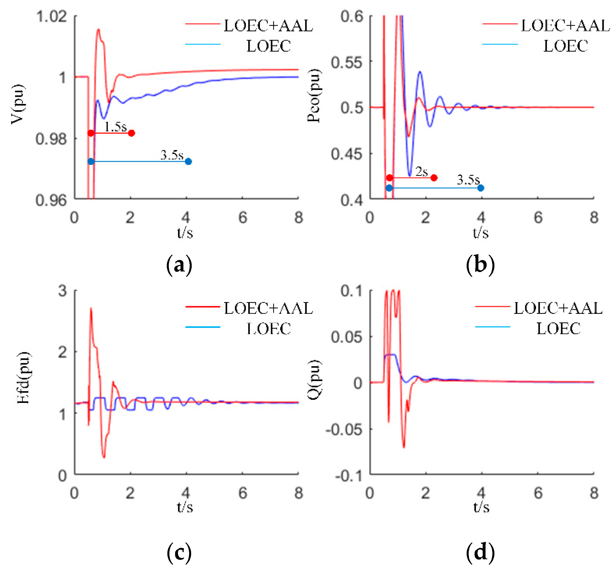
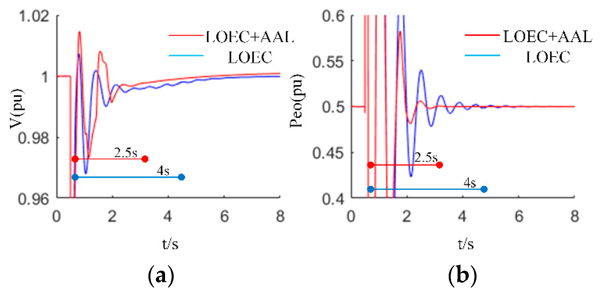
4.2. The Simulation Results

According to the analysis and parameters above, the effectiveness of the proposed strategy was compared with the traditional LOEC control strategy in this part. The contrast tests included different disturbances in the power system that could cause large disturbances on voltage or power-angle stability. Three typical disturbances were tested in the simulation verification. The three-phase short-circuit fault was divided into “proximal fault” and “remote fault”. The proximal fault occurred at a short distance from the synchronous generator; the short-circuit impedance was small and the terminal voltage fell to around 0.2 p.u. The remote fault occurred at a long distance from the synchronous generator; the short-circuit impedance was large and the terminal voltage fell to around 0.8 p.u. The disconnection fault occurred at one of the double transmission lines, which caused disturbance to the power angle.

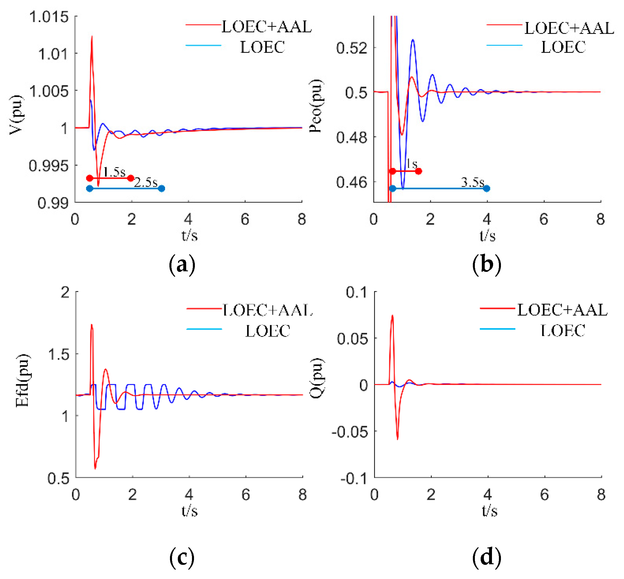
4.2.1. Three Phase Proximal Fault

The single-phase proximal fault occurred at 1 s and continued for 0.1 s. Figure 9 shows the contrasted results of terminal voltage, active power, field voltage, and the reactive power injection of the VSC. The LOEC + AAL could provide higher Efd and Q while the proximal fault occurred, and the excitation transformer could resist the impact within a short period, which brought better stability. As can be seen in Figure 9, the voltage returned to interval 1 within 1.5 s and the power angle returned to interval 1 within 2 s under the LOEC + AAL, whereas it needed more than 3.5 s under the LOEC.

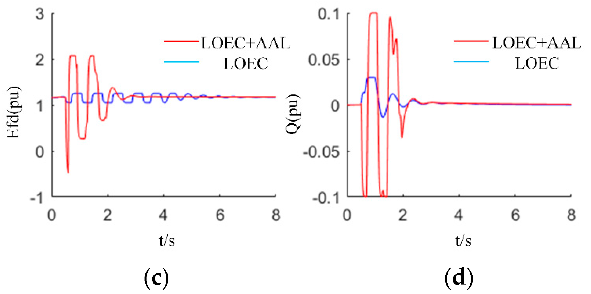
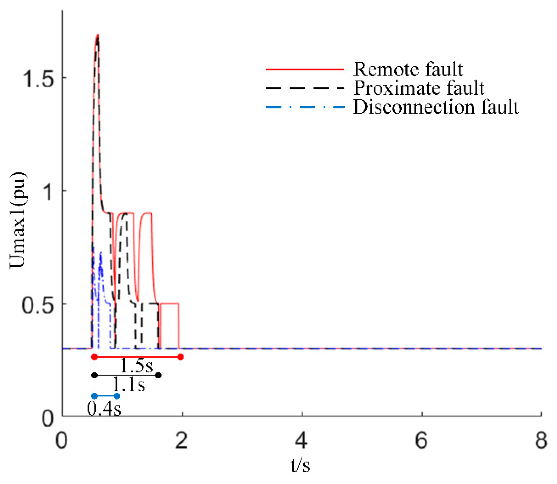
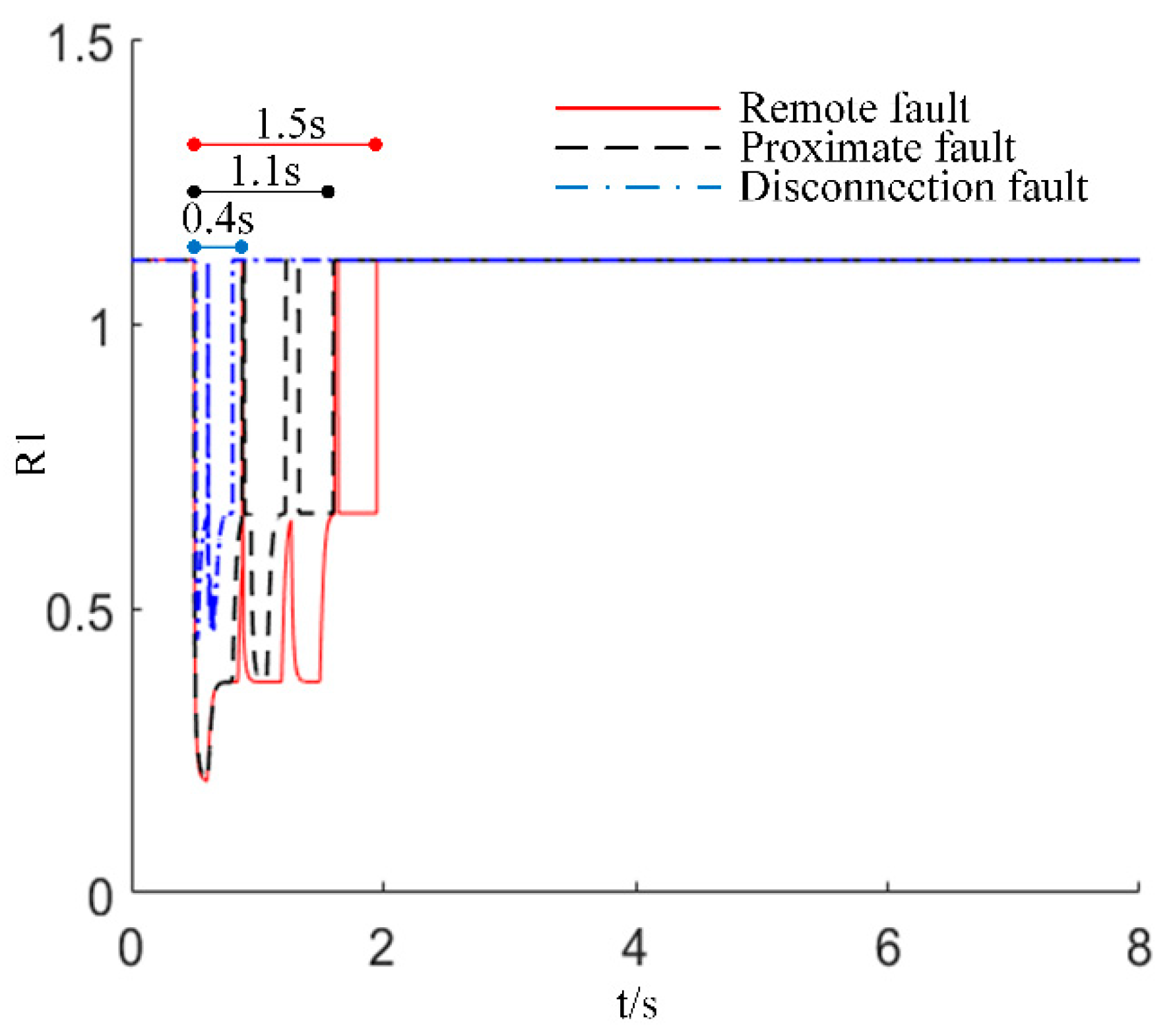
4.2.2. Three Phases Remote Fault

The three-phase remote fault occurred at 0.5 s and continued for 0.1 s. Figure 10 shows the contrasted results, which were similar to the results in Figure 9. In the transient period, the LOEC + AAL strategy increased the limit of field voltage and reactive power in a short time, which effectively stabilized the fluctuation in the power system and improved transient stability.

4.2.3. The Disconnection Fault

The disconnection fault occurred at 0.5 s and continued for 0.1 s. Figure 11 shows the contrasted results. The disconnection fault resulted in changes in system parameters, especially the system impedance, as the line of XL1 or XL2 was cut off, and, in this case, the LOEC + AAL controller could better improve the voltage and power stability than traditional LOEC. The system returned to the stable value within 1 s under the LOEC + AAL, which is a great improvement compared with the LOEC.
In summary, the LOEC + AAL coordinated controller stabilized the system within 2 s under large disturbances, which is a great improvement compared with the conventional LOEC strategy, according to Figure 9, Figure 10 and Figure 11. As the control objective was to keep the stability of the terminal voltage and the power angle, it was suitable to increase the field voltage Efd and the reactive power injection Q in a short period, which could be quickly stabilized after 3 s, and the safety of the excitation transformer could be guaranteed.

4.2.4. The Fuzzy Amplitude Limiter

The reference value of the fuzzy amplitude limiter is shown in Figure 12 and Figure 13. Taking the reference value of Umax1 (the output of the limiter to restrict the variation of field voltage) for example, the fuzzy amplitude limiter changed Umax1 according to different kinds of disturbances, in Figure 12. The weighted matrix R1 also changed in real-time corresponding to Umax1, in Figure 13. In these three typical fault cases, when the system was detected to enter the large disturbance interval (the interval 2) in which the voltage or the power angle exceeds the reference values of stability, the limiter opened and adjusted the duration according to the length of the fault. However, if the duration of the fault was too long (longer than 4 s), the limiter closed mandatorily to protect the safety of the excitation transformer. In the studied cases, the duration of transient periods was no longer than 2 s under the fuzzy amplitude limiter control.

5. Conclusions

The flexible excitation system can provide rapid reactive power injection for the synchronous generator, improve the stability of the terminal voltage as well as the power-angle stability, ameliorate the damping characteristics, and guarantee the robustness of the power system. In this paper, a kind of FES was introduced; the mathematical model of the coordinated control problem was figured out for designing the LOEC + AAL controller. The LOEC + AAL control strategy, which combines the methods of linear optimal excitation control, the adaptive amplitude limiter control, and the fuzzy logic control, was proposed for improving the stability of the power system and releasing the capability of the excitation transformer. The simulation results prove the effectiveness of the LOEC + AAL strategy, compared with the conventional LOEC algorithm. As the FES has been connected to the grid in field operation, the novel control algorithm proposed in this paper can be applied in engineering practice. In future works, the parameters of the LOEC + AAL controller will be calculated and tested in detail for industrial applications.

Author Contributions

Conceptualization, Y.P. and C.M.; Data curation, D.W.; Formal analysis, D.W.; Investigation, J.Z. and H.X.; Methodology, Y.P. and C.M.; Software, Y.P.; Supervision, J.Z. and T.Z.; Validation, J.Z. and T.Z.; Writing—original draft, Y.P.; Writing—review and editing, D.W. All authors have read and agreed to the published version of the manuscript.

Funding

This research was funded by the Science and Technology Project of State Grid Zhejiang Electric Power Co., Ltd. no. 5211DS19002L.

Institutional Review Board Statement

Not applicable.

Informed Consent Statement

Not applicable.

Data Availability Statement

Not applicable.

Conflicts of Interest

The authors declare no conflict of interest.

References

  1. Zhang, X.; Chen, J.; Zhang, G.; Wang, L.; Qiu, R.; Liu, Z. An Active Oscillation Compensation Method to Mitigate High-Frequency Harmonic Instability and Low-Frequency Oscillation in Railway Traction Power Supply System. IEEE Access 2018, 6, 70359–70367. [Google Scholar] [CrossRef]
  2. Yu, Y.; Ju, P.; Peng, Y.; Lou, B.; Huang, H. Analysis of Dynamic Voltage Fluctuation Mechanism in Interconnected Power Grid with Stochastic Power Disturbances. J. Mod. Power Syst. Clean Energy 2020, 8, 38–45. [Google Scholar] [CrossRef]
  3. Xie, D.; Xu, Z.; Yang, L.; Østergaard, J.; Xue, Y.; Wong, K.P. A Comprehensive LVRT Control Strategy for DFIG Wind Turbines with Enhanced Reactive Power Support. IEEE Trans. Power Syst. 2013, 28, 3302–3310. [Google Scholar] [CrossRef]
  4. Liu, B.; Wu, W.; Zhou, C.; Mao, C.; Wang, D.; Duan, Q.; Sha, G. An AC–DC Hybrid Multi-Port Energy Router With Coordinated Control and Energy Management Strategies. IEEE Access 2019, 7, 109069–109082. [Google Scholar] [CrossRef]
  5. Luo, J.; Bu, S.; Zhu, J.; Chung, C.Y. Modal Shift Evaluation and Optimization for Resonance Mechanism Investigation and Mitigation of Power Systems Integrated With FCWG. IEEE Trans. Power Syst. 2020, 35, 4046–4055. [Google Scholar] [CrossRef]
  6. Sun, R.; Abeynayake, G.; Liang, J.; Wang, K. Reliability and Economic Evaluation of Offshore Wind Power DC Collection Systems. Energies 2021, 14, 2922. [Google Scholar] [CrossRef]
  7. Wang, D.; Wu, J.; Li, C.; Tian, J.; Mao, C. Analysis and Conception of Power Generation Mode and Operation Control of Largescale Compressed Air Energy Storage System. Autom. Electr. Power Syst. 2019, 43, 13–22. [Google Scholar]
  8. Mao, C.; Malik, O.; Hope, G.; Fan, J. An adaptive generator excitation controller based on linear optimal control. IEEE Trans. Energy Convers. 1990, 5, 673–678. [Google Scholar] [CrossRef]
  9. Chen, Z.; Lu, J.; Mao, C.; Zhou, Y.; Wang, D. Design and implementation of voltage source converter excitation system to improve power system stability. IEEE Trans. Ind. Appl. 2016, 52, 2778–2788. [Google Scholar] [CrossRef]
  10. Zhou, Y.; Mao, C.; Chen, Z.; Lu, J.; Wang, D. A novel control strategy for static excitation system based on three-phase current source converter. In Proceedings of the 2015 5th International Conference on Electric Utility Deregulation and Restructuring and Power Technologies (DRPT), Changsha, China, 26–29 November 2015; pp. 1240–1245. [Google Scholar]
  11. Yu, M.; He, S.; Cheng, L.; Zhang, T.; Mao, C.; Wang, D.; Xiong, H.; Zhang, J. Coordination Control Strategy of Intensive Excitation on Flexible Excitation System. Large Electr. Mach. Hydraul. Turbine 2020, 43, 59–65. [Google Scholar]
  12. Zhang, T.; Mao, C.; Zhang, J.; Tian, J.; Yu, M.; Wu, K.; Xiong, H.; Wu, L.; Yu, H. Design and Field Application of Flexible Excitation System Damping Controllers. IEEE Trans. Ind. Electron. 2021, 68, 949–959. [Google Scholar] [CrossRef]
  13. Mao, C.; He, J.; Wang, D.; Lu, J. Multivariable Feedback Linearization Scheme for New Excitation Systems Based on Full Controlled Devices. Proc. CSEE 2013, 33, 53–60. [Google Scholar]
  14. Yang, J.; Chen, Z.; Mao, C.; Wang, D.; Lu, J.; Sun, J.; Li, M.; Li, D.; Li, X. Analysis and assessment of VSC excitation system for power system stability enhancement. Int. J. Electr. Power Energy Syst. 2014, 57, 350–357. [Google Scholar] [CrossRef]
  15. Cheng, L.; Zhang, T.; He, S.; Yu, M.; Mao, C.; Wang, D. Optimal Coordinated Control of Full-controlled Excitation System with Energy Storage System. In Proceedings of the 2020 IEEE/IAS Industrial and Commercial Power System Asia (I&CPS Asia), Weihai, China, 13–16 July 2020; pp. 527–535. [Google Scholar]
  16. He, N.; Liu, Z. A Fuzzy automatic voltage and reactive power control device with self-recognition. Power Syst. Technol. 2000, 24, 52–56. [Google Scholar]
Figure 1. Three-level voltage source flexible excitation system.
Energies 14 05212 g001
Figure 2. Philips–Heffron model based on flexible excitation system.
Energies 14 05212 g002
Figure 3. Mode selection of the amplitude limiter.
Energies 14 05212 g003
Figure 4. Fuzzy control membership function. (a) three-dimensional view (b) relationship of ΔPeo and ΔUt (c) relationship of Umax and ΔUt (d) relationship of Umax and ΔPeo.
Energies 14 05212 g004aEnergies 14 05212 g004b
Figure 5. Coordinated control strategy based on decoupling control of stator and rotor.
Energies 14 05212 g005
Figure 6. The control diagram of LOEC + AAL.
Energies 14 05212 g006
Figure 7. Structure of simulation platform.
Energies 14 05212 g007
Figure 8. Structure of LOEC + AAL controller.
Energies 14 05212 g008
Figure 9. Comparison of coordinated control and traditional control under the single phase proximal fault. (a) terminal voltage (b) active power (c) field voltage (d) reactive power injection.
Energies 14 05212 g009
Figure 10. Comparison of coordinated control and traditional control under the three phase remote fault. (a) terminal voltage (b) active power (c) field voltage (d) reactive power injection.
Energies 14 05212 g010aEnergies 14 05212 g010b
Figure 11. Comparison of coordinated control and traditional control under the disconnection fault. (a) terminal voltage (b) active power (c) field voltage (d) reactive power injection.
Energies 14 05212 g011
Figure 12. The fuzzy amplitude limiter for Umax1.
Energies 14 05212 g012
Figure 13. The fuzzy amplitude limiter for R1.
Energies 14 05212 g013
Table 1. Fuzzy Control Rules for Amplitude Limiter.
Reference ValueActive Power Deviation ΔPeo
Voltage deviation ΔVt LSLMSHH
LMNLLSLSL
SLLLSLSLM
MSLSLMMSH
SHMMSHSHH
HSHSHHHMX
Table 2. Parameters of simulation experiment.
ParameterValue
Rated terminal voltage10.5 kV
Rated system voltage220 kV
Voltage rate of main transformer220 kV/10.5 kV
Voltage rate of excitation transformer10.5 kV/380 V
Rated frequency50 Hz
Rated capacity of VSC6.47 Mvar
Rated capacity of synchronous generator64.7 MVA
Rated capacity of main transformer150 MVA
Reactance of main transformer0.1 pu
Reactance of power line0.23 pu
d-axis transient reactance Xd’ of synchronous generator0.314 pu
d-axis transient time constant Tdo’ of synchronous generator7.31 s
Publisher’s Note: MDPI stays neutral with regard to jurisdictional claims in published maps and institutional affiliations.

