1. Introduction
One of the most important problems in underground coal mining is the Gas Dynamic Phenomenon (GDP). At the end of the 20th century, due to an increase in the depth of mining operations and their mechanisation, there has been an increase in GDPs, resulting in numerous instances of material and human damage. In recent decades, rigorous research has been carried out in order to understand the phenomenon and establish control measures [
1], but the preventive techniques have not reached the full guarantee during the advance of the work face.
The analysis of GDPs indicates that their appearance is caused by the stress conditions of the ground, the presence of gas, and the combination of both factors [
2,
3,
4].
There are numerous indicators of risk:
Between the preventive techniques are among others:
The last preventive technique, the injection of water, is used with the end of increasing the level of moisture and reducing the capacity of the coal to accumulate elastic deformation energy and increasing its plastic deformation energy [
11,
12]. This is because when the humidity of coal under high-pressure increases, water molecules try to occupy the empty spaces and displace the methane molecules, reducing the gas content. However, when the injection ends, the moisture decreases and the gas content can rise again, so the effect is short in time.
The injection of water is also influenced by other parameters such as pressure, time, flow [
13] and the depth of the injection [
14,
15]. But also, by the presence of joints in the rock. In this case, it is possible to have instantaneous outbursts of water [
16], because the increase in the density of joints increases the larger pore pressure in a larger zone leading to the instantaneous outburst of water. To control the injection of water, in 2011, [
17] design the non-contact high-pressure water injection flow meter using magnetic technology.
In the last decade, the studies have focused on the evaluation of the effectiveness of the injection of water by numerical simulations [
18,
19] and by laboratory tests [
15].
However, the adverse effects that may be caused by the injection of water make it necessary to find new degasification methods, over and above fracturing, that make mining work safer by improving the permeability of the soil and facilitating the possible recovery of gas for subsequent use.
This work analyses an alternative and innovative method of fracturing and degassing coal, but without using conventional explosives, which would be counterproductive in a gasified ground. The method employs the pyrotechnic device called PYROC (Pyrotechnic Break Cartridges).
For this analysis, medium-scale tests of the generation of CO2 into coal samples are carried out. The effect of the generation of CO2 is analysed by comparing the initial permeability and the final permeability of the coal samples with an injection of methane.
Then, to verify the effect of high-pressure CO2 generation on medium-scale coal samples, the front face of one of the sublevels of a mining operation has been numerically simulated with a hydromechanical using the FLAC-2D software application.
After the discussion of the results, it is possible to say that the PYROC system is effective in degassing coal and therefore increases safety in mining operations.
2. Medium-Scale Tests of Generation of CO2 into Coal Samples
The generation of CO2 under pressure into coal seams opens up ways of circulation in the coal matrix, facilitating the emission of methane to the outside and improving the safety of mining operations. To analyse its effectiveness, the variation of methane permeability before and after the generation of CO2 is evaluated in medium-scale laboratory tests.
Starting with a coal sample of 1 m3, the coal face and the real conditions are simulated in the sample by means of a steel box of 1 m inner side and 1.30 m high, leaving the top face free. In this way, the real confinement of the coal in a block tangent to the walls of the gallery is simulated. Because the sample to be tested was defragmented during the process of breaking and extraction of the seam, the sample is mixed with a cement proportion of 3% by weight to increase its consistency.
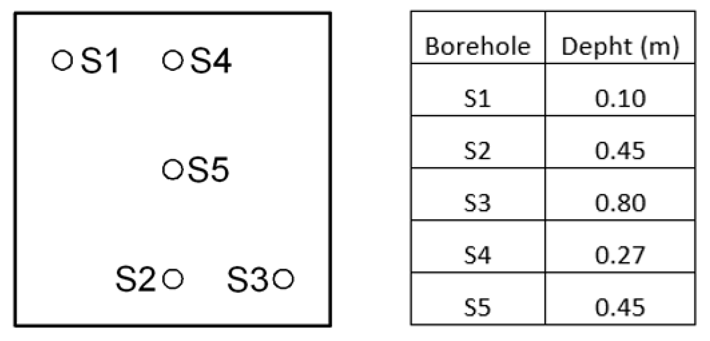
In the free face of the box, five boreholes with copper piping are drilled at different depths that simulate those drilled in the front face. CO
2 is generated from one of them (S5) using the PYROC system. This system consists of a directional gas pressure mechanism used to break up large rock fragments [
20,
21]. It achieves a very low detonation velocity of approximately 50 m/s, compared to 200 m/s for slow explosives and 7000 m/s for fast explosives [
22]. This very low velocity allows safe underground blasting because the deflagration does not cause projections but cracks in the coal due to the pressure of the CO
2 generated. Moreover, in this case, there is no limit to the depth of the blast hole, as there is no danger of projections or collapse.
Figure 1 shows the position and the depth of the boreholes.
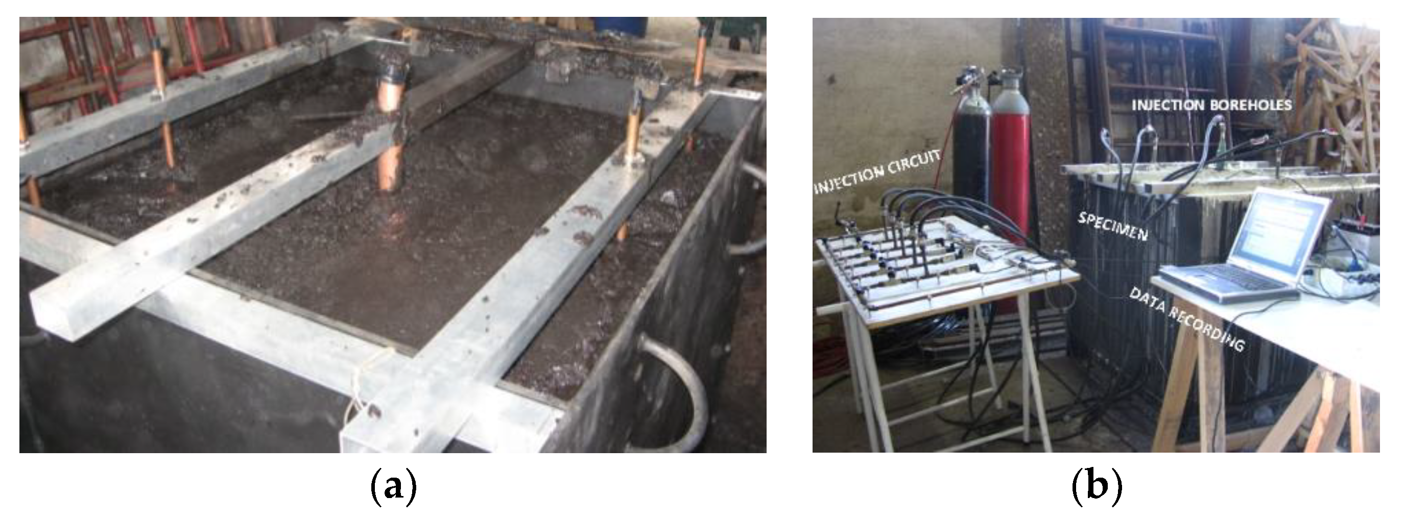
A pressure sensor (
Figure 2a) is placed in each borehole and the information is transferred to a computer (
Figure 2b).
The test is carried out in three steps:
- 1.
Initially, the permeability of the sample is determined by injecting methane in a controlled manner through the copper tube of the borehole S2 and measuring the evolution of the pressure overtime at the deepest end of the rest of the boreholes. Due to the different depths of the boreholes, the end closest to the injection in borehole S2 is S5 followed by S3, S4 and S1, respectively.
- 2.
Then, CO2 is generated by the PYROC system located in the borehole S5 with the end of fracturing the coal sample.
- 3.
Finally, the permeability test is repeated to evaluate the effectiveness of the process by comparing the permeability to the methane obtained at this point with the permeability to the methane obtained at the initial point of the test.
2.1. Calculation of the Initial Permeability of the Coal Sample
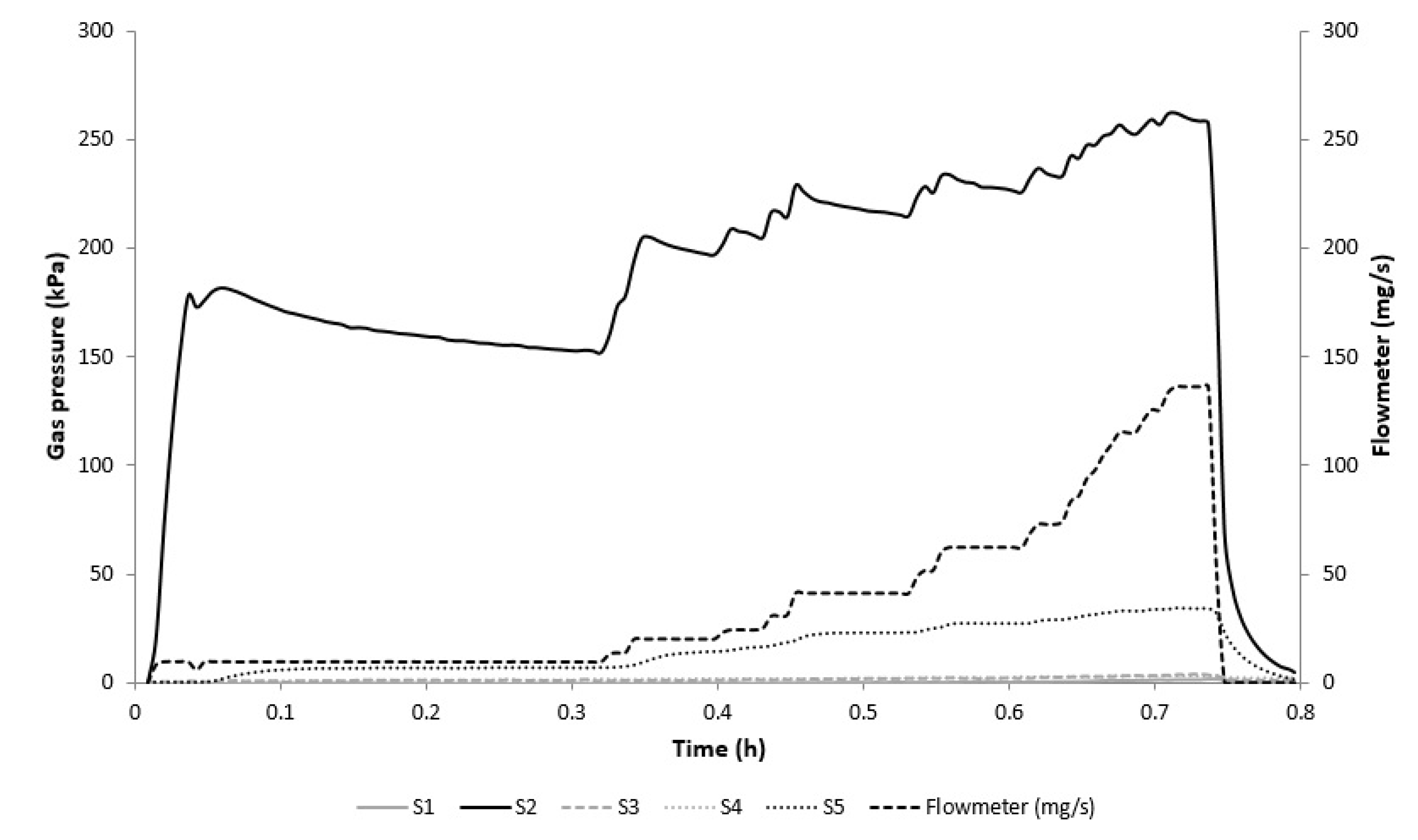
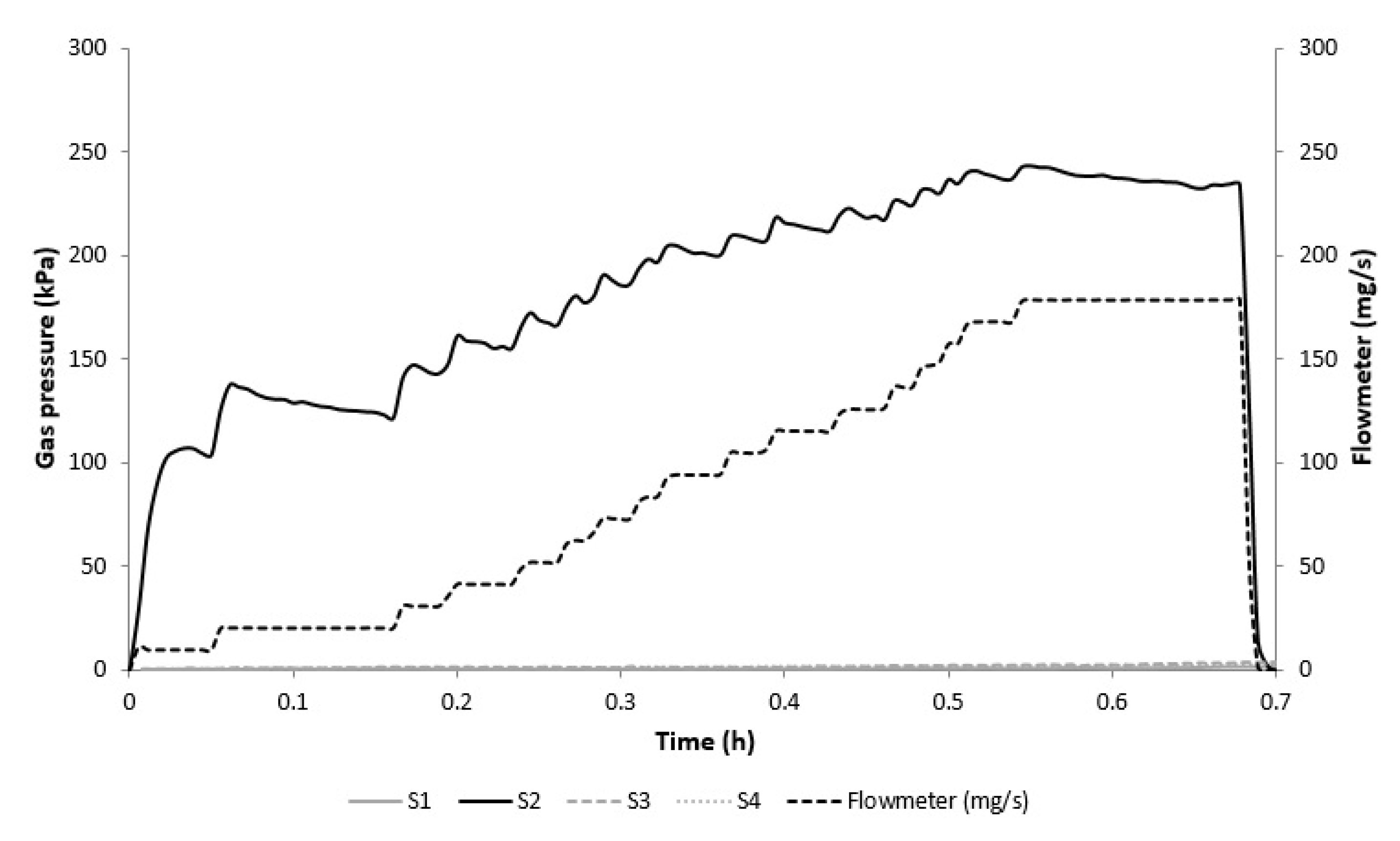
Figure 3 shows the pressure evolution in each borehole as methane is injected into the sample. In the borehole of injection S2, low flow rates are injected at the beginning of the test until the pressure at the borehole sensor stabilises. Then, the inlet gas flow rate is increased until the pressure becomes stable again at 260 kPa. At this point, the discharge process begins. Borehole S5 shows the largest pressure variation due to its proximity to the injection borehole S2. The pressure variations detected in the rest of the boreholes are between 45 kPa and 2 kPa. In addition, as the inlet flow increases, the increase of the pressure in the boreholes is more noticeable.
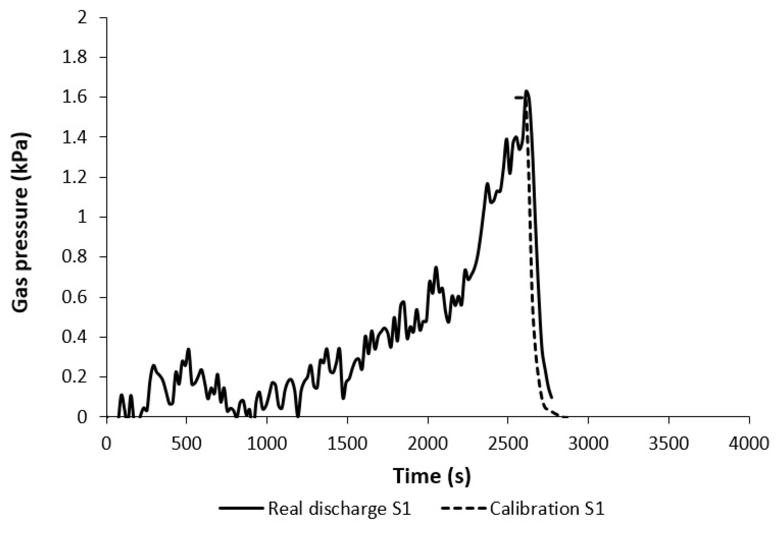
After this test, the permeability of the coal in the sample is calibrated as a function of gas pressure. For this purpose, a simulation is carried out, using FLAC-2D [
23], of the gas discharge that occurs in S1, S3, S4 and S5 after the end of the injection of methane in borehole S2. Since each of the discharges is produced from different pressure values, this analysis allows us to know the pressure/permeability relationship and to compare it with that obtained in small-scale laboratory samples for the same gas. The real samples were extracted at the front face with the help of a device designed and patented by the Ground Engineering Group of the University of Oviedo [
24].
The generated model consists of a grid with the dimensions of the small sample and a gas pressure measurement point that simulates the borehole analysed in each case. It should be noted that the model only considers gasodynamic calculations because although the mechanical behaviour is important, the model focuses on a local level and not on a global level without considering the influence of other works. For the calibration, the properties of the coal are modified until the pressure-time plot from the model is similar to the real pressure-time plot.
Figure 4 shows the real graph of the discharge in borehole S1 and the calibration graph obtained with the model in the same borehole. Both plots are very similar, ensuring that the value of the coal permeability entered into the model matches the real value.
Table 1 shows the results of the permeability calibrations carried out in the five boreholes.
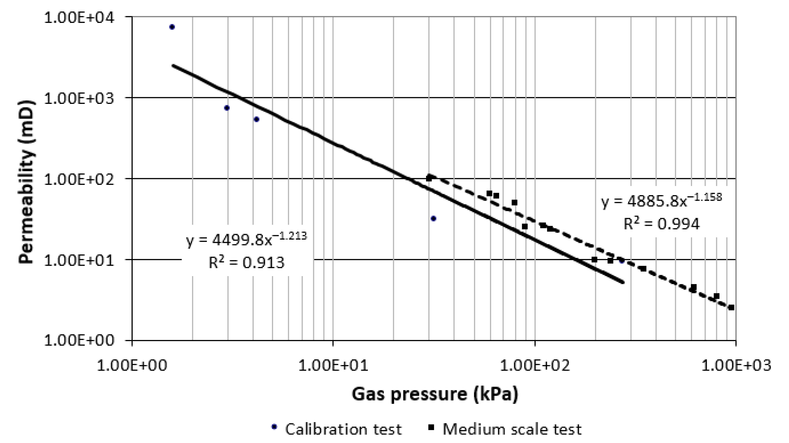
Figure 5 shows the results of the calibration and those obtained in the medium-scale laboratory tests. It can be seen that the relationship between the pressure and the permeability in both cases is very similar. There is a good correlation between the two curves, although the results obtained in the calibration show a slightly higher permeability than those of the medium scale. This is because the medium scale tests are equivalent to tests in coal with confinement and, due to this circumstance, the stress state in the coal is higher and the permeability is reduced.
2.2. Fracturing of the Coal Sample Using the PYROC System
In this second step, methane is injected into three of the four effective boreholes to reproduce the real conditions of a coal seam in the mine and the high-pressure gas generator device is introduced in borehole S5. After deflagration, the mixture mainly generates CO2 which expands at a velocity close to that of a detonation (50 m/s), causing fracturing of the coal without projection.
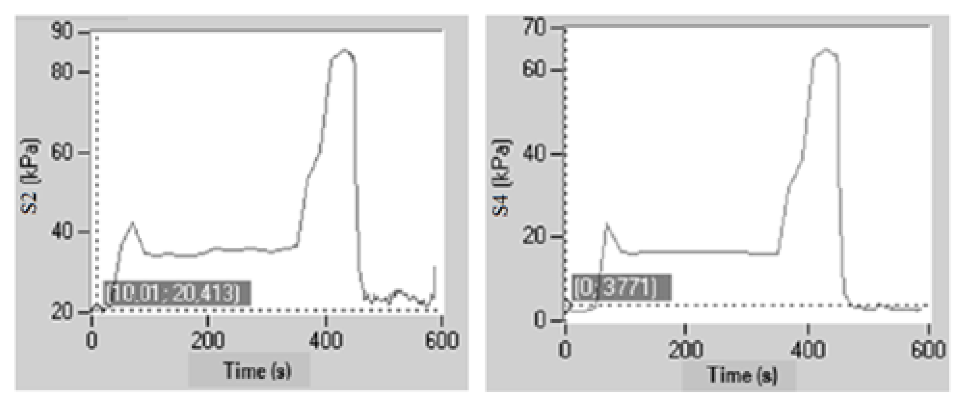
Figure 6 shows the pressure variations in boreholes S2 and S4 after the injection of methane and deflagration with the PYROC system. It can be seen that, after the fracturing caused by the controlled deflagration, the methane gas pressure decreases below pre-detonation levels after a period of time equal to 1 min has elapsed. This pressure drop demonstrates the high effectiveness of the analysed process.
2.3. Calculation of the Final Permeability of the Coal Sample
The test ends by studying the permeability of the coal sample in a similar way to how the initial permeability was determined, with the exception that in this case the pressure sensor in borehole S5 is not used as it was rendered unusable after the initiation of the fragmentation device. In this case, the pressure variations in the control boreholes are very small (
Figure 7).
The calibration of the final methane permeability is performed following the same procedure as the calibration of the initial permeability. As in the first case, the correlation between the real value and the simulated value is very good. If the final permeability value obtained with the numerical model in borehole S2 (31 mD) is compared with the initial value (9.5 mD), a large increase in permeability is observed, facilitating the flow of gas.
Table 2 shows the pressure of calibration and the permeability from the calibration after sample fracturing.
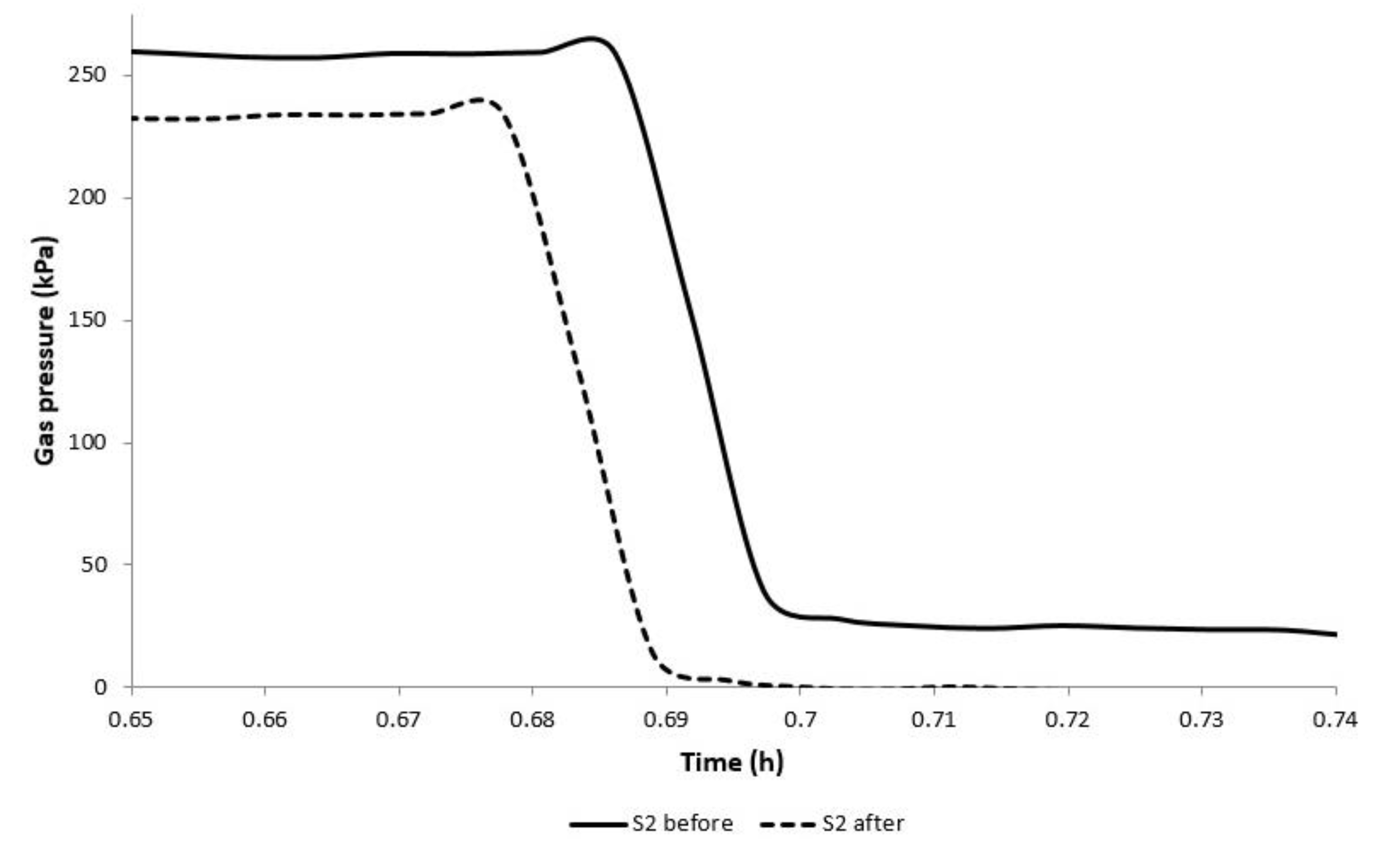
On the other hand, and contrary to what happens with the pressure, the value of the rate of flow increases notably. The purpose of this increase is to equalise the injection pressures used in the calculation of the initial permeability. While in the first calculation 100 g of methane are introduced, in the second calculation 230 g are injected. In other words, to achieve the same stabilisation pressure in both permeability calculations, more gas is injected in the second calculation, which indicates a larger void volume. This increase in the volume of voids is observed in the comparison of the two pressure-time plots once the injection ceases (
Figure 8). When the coal has been fragmented by the PYROC system, the drop in pressure occurs faster and the gas can move easier.
All observations made after the sample was fractured indicate that new ways of circulation for the gas have been opened, i.e., the permeability of the coal has been improved by the high-pressure CO2 generation fracturing test.
3. Numerical Simulation of the Generation of CO2 in Coal
Once the effect of high-pressure CO2 generation on medium-scale coal samples has been verified, the front face of one of the sublevels of a mining operation has been numerically simulated with a hydromechanical model. The simulation is carried out by means of finite difference using the FLAC-2D software application. The numerical simulation analyses the influence of the borehole length and pressure of the gas, as well as the initial permeability of the coal on the relaxed zone, simulating the gas circulation by means of applying a normal pressure of gas to the walls of the borehole.
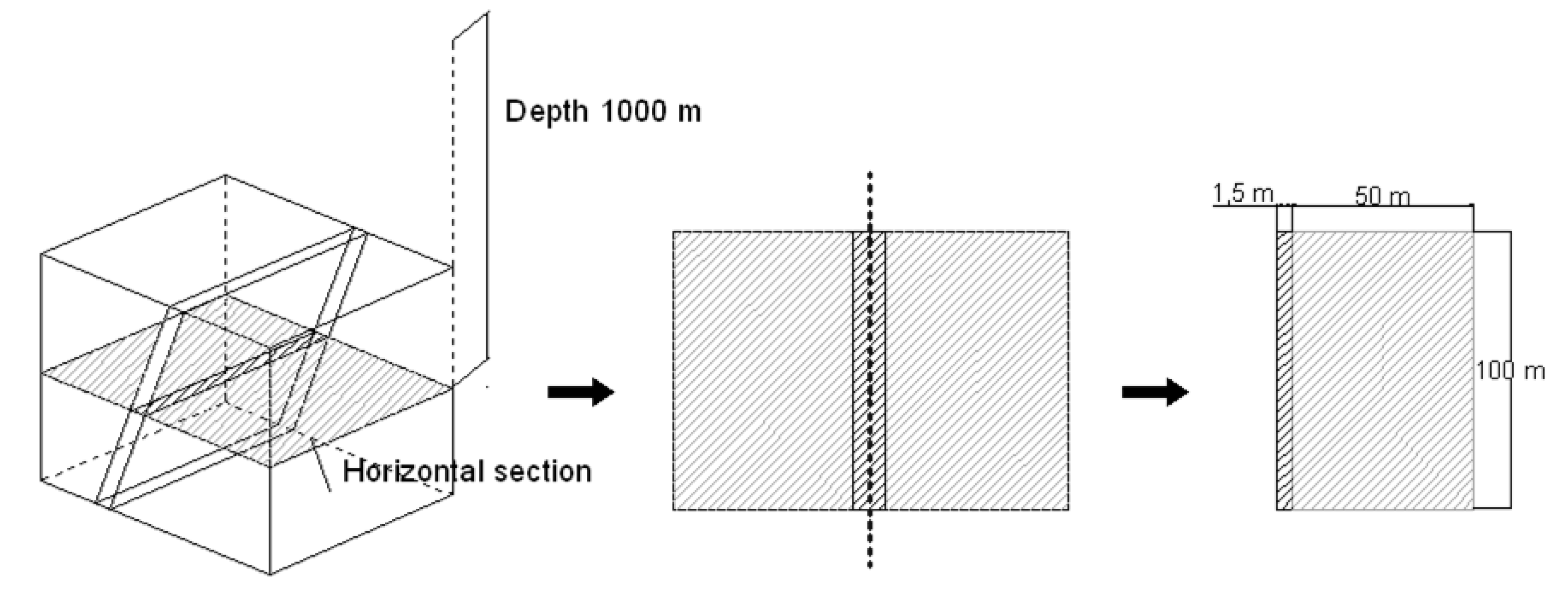
The numerical model simulates a horizontal cut of the rock mass in which the coal seam is located. It is a simple model that only considers the existence of the walls and a steeply dipping coal seam as they usually appear in the Asturian Central Basin [
10]. Moreover, it is asymmetric to simulate one of the infinite sections of the gallery. Finally, in order to reproduce the mining conditions, the model is subjected to horizontal and vertical stresses similar to those supported by an area located at 1000 m depth, as this is the level of many of the coal mines in Asturias (
Figure 9).
Table 3 shows the mechanical properties of the modelled materials obtained from numerous projects carried out in coal mines in the Asturias Central Basin [
9,
11,
25].
Numerical simulation is carried out in a process of four steps:
Initial state. Once the geometry is generated, the properties and pressures are introduced, and the model is allowed to stabilise until the initial stress readjustment is reached. This is the initial stress state in the modelled area.
Advance of the gallery. An advance of 50 m is simulated in a gallery with a width similar to the width of the seam. This gallery is supported, as in the real workings, to prevent the open hole from closing.
Face drilling. A borehole is drilled at the face, along the axis of the coal seam. The borehole is supported to simulate the tubing that is placed in reality but has varying diameters and lengths.
Injection of CO2. The pressurised gas is applied in the last metres of the borehole and its circulation is analysed both in the seam and in the wall to know the zone affected by the injection (relaxed zone).
Table 4 shows some of the models created as a function of borehole length, injection pressure and material permeability. The injection pressure is very high to simulate the deflagration generated with the PYROC system and analyse the most suitable pressure for the system.
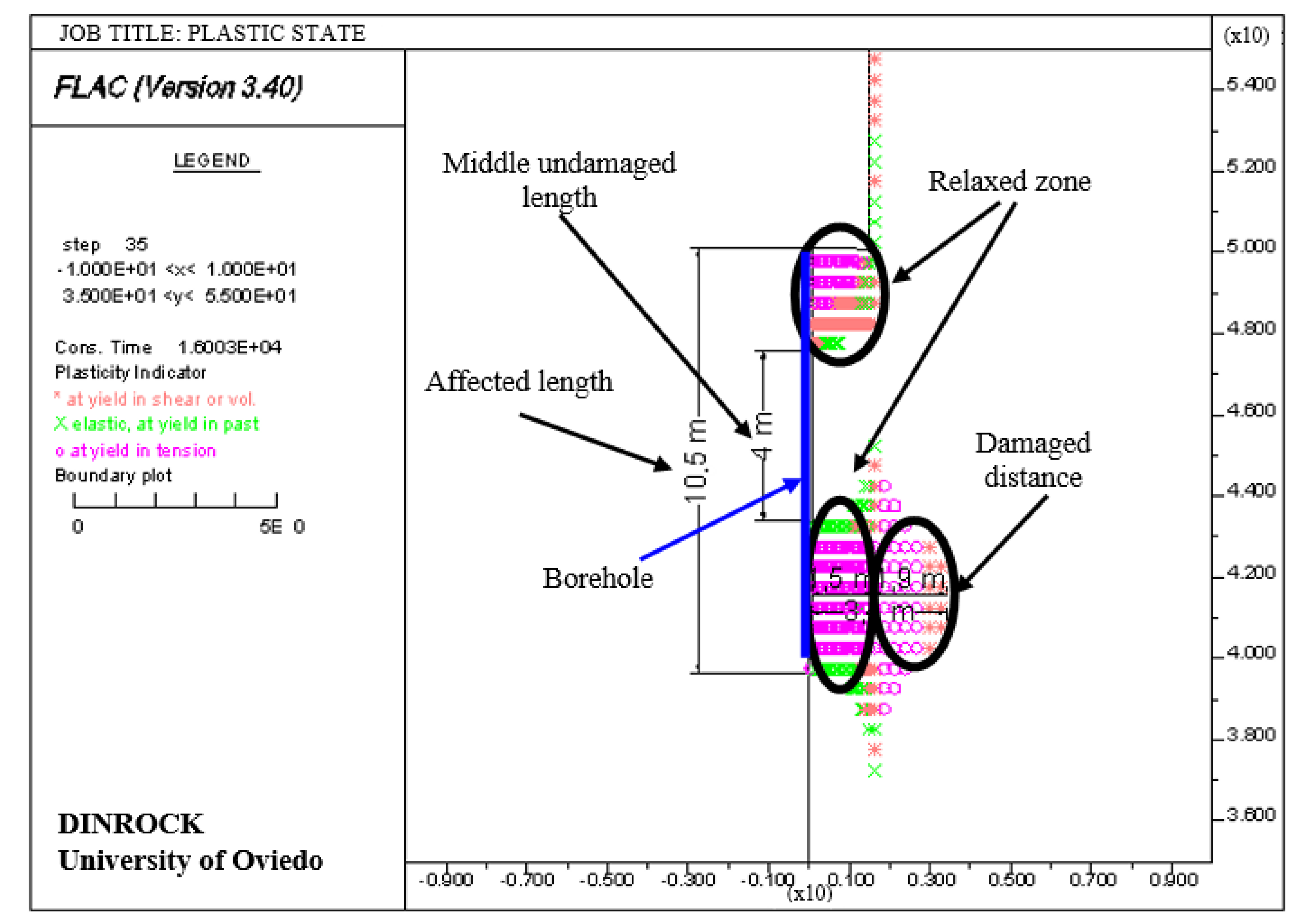
Figure 10 shows the plastic state obtained for model 2. The central vertical line in the figure represents the borehole carried out at the front, which in its upper and lower part shows relaxed zones and between them an undamaged zone of about 4 m in length. In addition, close to the lower relaxed zone there is a damaged zone.
At this point, it is necessary to remember that the longer the length of the relaxed zone and the smaller the intermediate undamaged and the damaged zones, the more suitable an injection method is. The existence of the intermediate undamaged zone implies a possible accumulation of gas behind the front, while the damaged distance implies that both the wall of the layer and the crown of the gallery can be fractured.
Once the different models have been simulated, a comparison is made between them in which the influence of borehole length and injection pressure is analysed, as well as the initial permeability of the coal on the relaxed zone.
3.1. Influence of Borehole Length and Injection Pressure on the Relaxed Zone
None of the models made with boreholes of 10 m in length is in optimal condition. In all of them, there is an intermediate undamaged zone and very extensive damaged zones in walls and crown.
In the models made with boreholes of 7.5 m in length, something similar to the models with boreholes of 10 m occurs, although not so markedly. In this case, it is possible to work at intermediate pressures, of the order of 50 MPa, which increases the length of the relaxed zone and eliminates the intermediate undamaged zone, although damage to the roof and walls of the order of 1.5 m in thickness is generated. Therefore, a low-pressure injection could be used with complementary treatments to relax the intermediate zone.
In the models carried out with boreholes of 5 m in length, the damaged distance in the roof and walls decreases significantly with respect to the previous cases and there are even injections that meet the indicated requirements, as shown in
Figure 11. Besides, if the pressure of injection is 10 MPa, the affected and relaxed zones coincide (2.5 m long), there is no intermediate undamaged zone and the walls and crown are not damaged. However, given the small size of the relaxed zone, this model would not be viable from an economic and operational point of view because it would generate a long delay in the work. On the other hand, injecting at 50 MPa or 100 MPa would increase the relaxed length to 6 m, which would improve from a production point of view. In this case, the depth of the walls and roof is 1 m.
3.2. Influence of Initial Coal Permeability on the Relaxed Zone
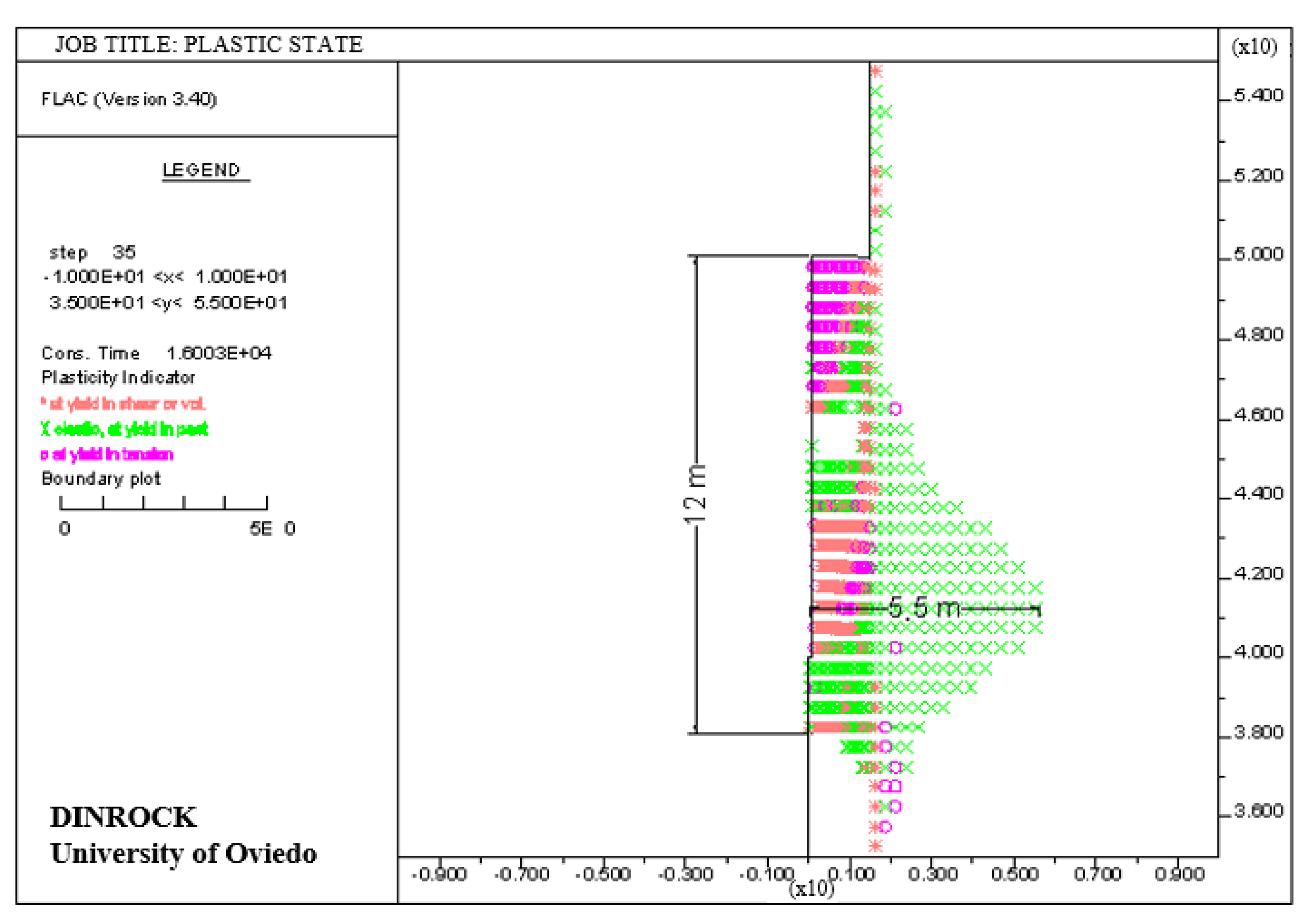
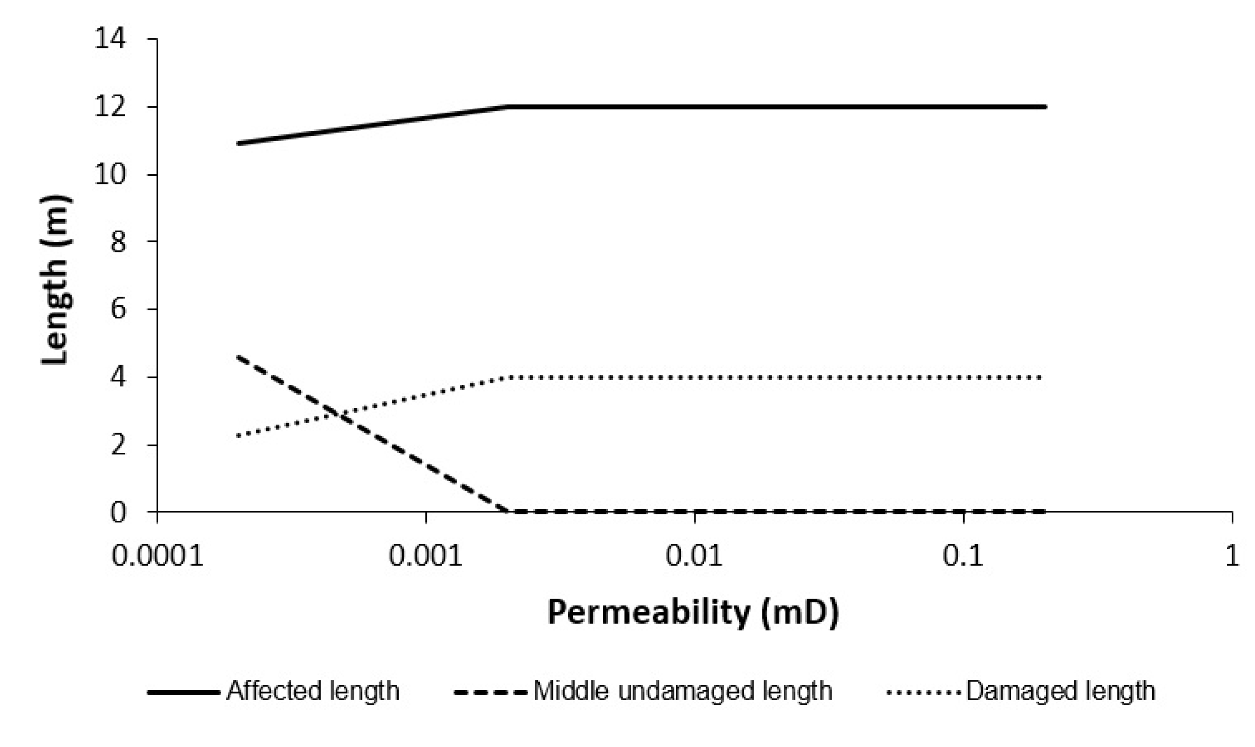
The simulation is performed for a 10 m long borehole, an injection pressure of 100 MPa and permeabilities of 0.0002 mD, 0.002 mD, 0.02 mD and 0.2 mD. The analysis of the simulation shows that there are no significant changes in permeabilities greater than 0.002 mD and that the plastic states are very similar to
Figure 12 where the entire length of the borehole is relaxed, but with damaged zones in the walls with a length of 4 m.
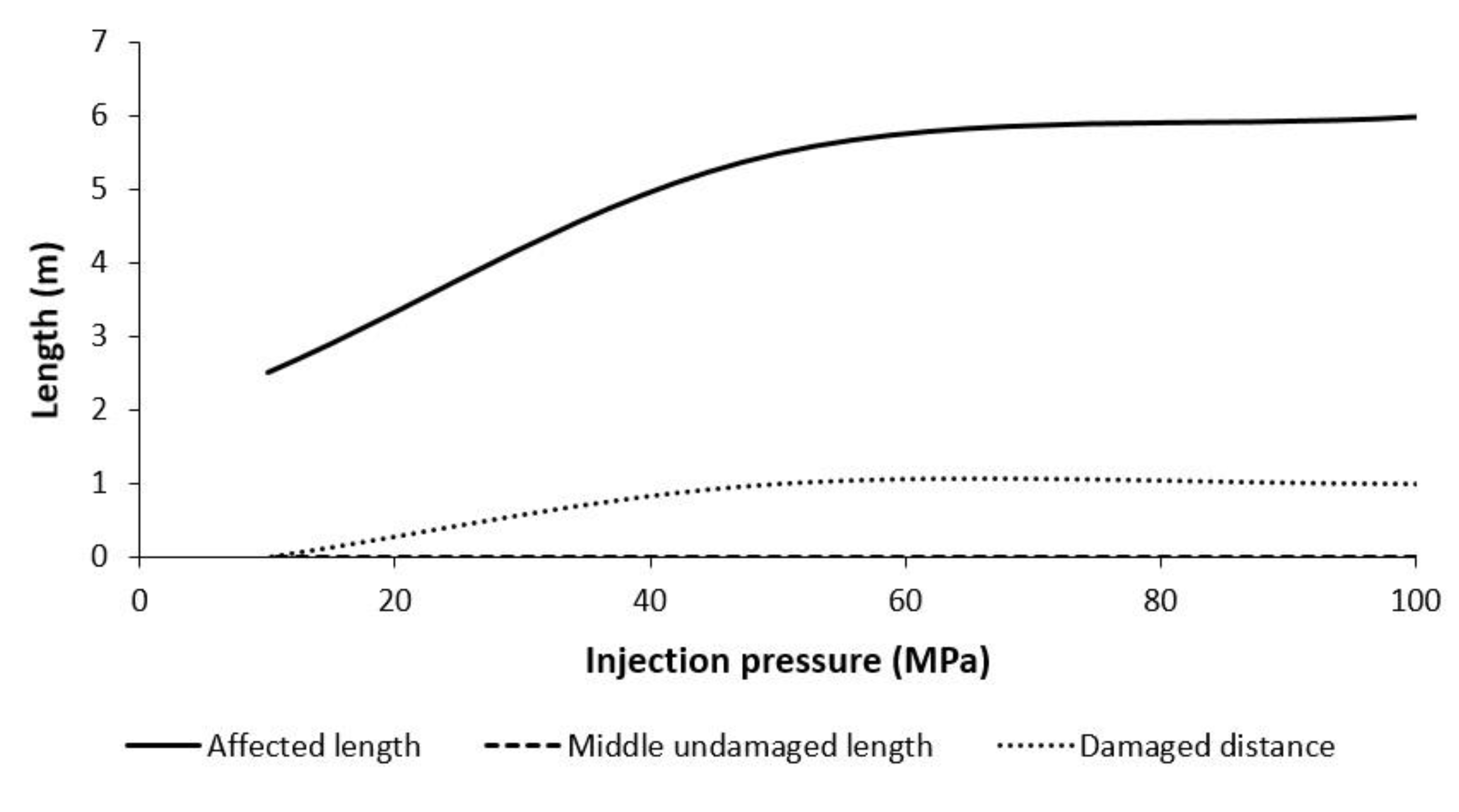
Figure 13 shows the affected, damaged, and undamaged zones as a function of permeability. It can be seen that as the permeability of the coal decreases below 0.002 mD, the length of the zone affected by the treatment decreases, the intermediate undamaged zone increases and the damaged zone in the walls and roof decreases. As permeability increases above 0.002 mD, little change in behaviour is observed.
4. Discussion
The generation of CO2 into a point in one coal layer creates a zone of influence around that point, where the coal fractures, relaxes, and degasses.
Depending on the pressure of the generation of CO2 and therefore, the pressure of the injection of CO2, the compressive strength of the coal and its permeability, the affected zone will reach the coal face or will be ahead of the coal face and separated from the relaxed zone by an unaffected zone. So, it is necessary to perform a check during the process of generation to confirm that the injected zone reaches the coal face.
Besides, high pressures (over 100 MPa) can cause damage to the walls while low-pressures (less than 10 MPa) increase the likelihood of unaffected intermediate zones unless the length of injection and thus the protected zone is reduced.
On the other hand, for constant borehole lengths and injection pressures, initial coal permeability values below 0.002 mD increase the undamaged intermediate zone, while with greater values relax the entire length of the borehole, although with damaged zones on the walls with a length of 4 metres.
At last, the presence of unaffected zones can lead to overloaded zones that act as containment dikes for the injected fluid, compromising the safety of the advance. In this case, a subsequent treatment must be carried out by communicating both zones by means of distension boreholes or injections at progressive distances from inside of the rock mass towards the front.
5. Conclusions
From the studies carried out, it can be said that the generation of CO2 with the pyrotechnic device PYROC:
Fractures and degasses the coal increasing the permeability from 9.5 mD to 31 mD in the borehole of injection.
Decreases the methane gas pressure below pre-detonation levels after a period of time equal to 1 min has elapsed.
Achieves decompressed lengths between 8 and 10 m ahead of the face with pressures of injection of 50 MPa.
Relaxes the total length of the borehole of injection for initial coal permeability values equal to or greater than 0.002 mD.
Allows working with low permeable coals, with high induced stresses and high methane concentrations by not using conventional explosives.
Increases safety in mining operations.
Author Contributions
Conceptualization, C.G.-N. and M.-I.Á.-F.; methodology, C.G.-N. and M.-I.Á.-F.; formal analysis, M.-B.P.-G. and J.-C.P.-E.; lab tests, M.-B.P.-G. and J.-C.P.-E.; writing—original draft preparation, M.-B.P.-G. and J.-C.P.-E.; writing—review and editing, M.-B.P.-G. and M.-I.Á.-F.; supervision, C.G.-N. and M.-I.Á.-F. All authors have read and agreed to the published version of the manuscript.
Funding
This research received no external funding.
Institutional Review Board Statement
Not applicable.
Informed Consent Statement
Informed consent was obtained from all subjects involved in the study.
Data Availability Statement
The data presented in this study are available on request from the corresponding author. The data are not publicly available due to confidentiality.
Acknowledgments
The information and technical and logistic support provided by those responsible for the Sotón Pit (HUNOSA), where mining work takes place in the area under study, was of inestimable help in the carrying out of this research study.
Conflicts of Interest
The authors declare no conflict of interest.
References
- United Nations. Economic Commission for Europe. Best Practice Guidance for Effective Methane Drainage and Use in Coal Mines, 2nd ed.; UN Publication: New York, NY, USA, 2016. [Google Scholar]
- Fernandez-Diaz, J.J.; Gonzalez-Nicieza, C.; Alvarez-Fernandez, M.-I.; Lopez-Gayarre, F. Analysis of gas-dynamic phenomenon in underground coal mines in the central basin of Asturias (Spain). Eng. Fail. Anal. 2013, 34, 464–477. [Google Scholar] [CrossRef]
- Krause, E.; Skiba, J. Formation of methane hazard in longwall coal mines with increasingly higher production capacity. Int. J. Min. Sci. Technol. 2014, 18, 403–407. [Google Scholar] [CrossRef]
- Fan, C.; Li, S.; Luo, M.; Du, W.; Yang, Z. Coal and gas outburst dynamic system. Int. J. Min. Sci. Technol. 2017, 27, 49–55. [Google Scholar] [CrossRef]
- Ministry of Industry. Technical Specification 0307-2-92: Methane Desorption Rate Measurement Method; Ministry of Industry: Moscow, Russia, 1992.
- Jahns, H. Measuring the strength of rock in situ at an increasing scale. In Proceedings of the First International Society for Rocks Mechanics Congress, Lisbon, Portugal, 25 September–1 October 1966. [Google Scholar]
- Braüner, G. Rockbursts in Coal Mines and Their Prevention; Balkema: Rotterdam, The Netherlands, 1994. [Google Scholar]
- Wang, Y.; Yang, Q. Prediction of outburst hazard of coal and gas. In Proceedings of the 22nd International Conference of Safety in Mines Research Institutes, Beijing, China, 2–6 November 1987. [Google Scholar]
- Álvarez-Fernández, M.I.; González-Nicieza, C.; Álvarez-Vigil, A.E.; Herrera-García, G.; Torno, S. Numerical modelling and analysis of the influence of local variation in the thickness of a coal seam on surrounding stresses: Application to a practical case. Int. J. Coal. Geol. 2009, 79, 157–166. [Google Scholar] [CrossRef]
- Kissell, F.N. Handbook for Methane Control in Mining; Pittsburgh Research Laboratory: Pittsburgh, PA, USA, 2006; p. 188. [Google Scholar]
- Hargraves, A.J. Instantaneous outbursts of coal and gas—A review. Proc. Aust. Ins. Min. Metall. 1983, 285, 1–37. [Google Scholar]
- Lan, T.; Fan, C.; Zhang, H.; Batugin, A.S.; Ruibin, L.; Yang, Y.; Jia, C. Seepage law of injected water in the coal seam to prevent rock burst based on coal and rock system energy. Adv. Civ. Eng. 2018, 2018, 1–9. [Google Scholar] [CrossRef]
- Quian-Cheng, F.; Zhi-Quiang, L.; Ke-Ping, Z. Study of rational water injection parameters of hydraulic pressing preventing outburst measure based on numerical simulation. Procedia Eng. 2011, 26, 1097–1103. [Google Scholar] [CrossRef][Green Version]
- Ting-kan, L.; Zai-feng, Y.; Fang-Tao, C. Outburst control in soft and outburst prone coal seam using the waterjet slotting technique from modeling to field work. Int. J. Coal. Sci. Technol. 2012, 18, 39–49. [Google Scholar]
- Nguyen, D.V.; Nguyen, H.P.; Do, T.M. Experimental study on the efficacy of water infusion for underground mining of a coal seam. Appl. Sci. 2019, 9, 3820. [Google Scholar] [CrossRef]
- Yang, T.H.; Xu, T.; Liu, H.Y.; Tang, C.A.; Shi, B.M.; Yu, Q.X. Stress-damage-flow coupling model and its application to pressure relief coal bed methane in deep coal seam. Int. J. Coal. Geol. 2011, 26, 357–366. [Google Scholar] [CrossRef]
- Xiao, D.; Zhou, Q.; Liu, J.; Liu, S.; Yu, L. The mechanism of non-contact high pressure water injection flow meter for plunger pump. Procedia Earth Planet Sci. 2011, 2, 76–82. [Google Scholar] [CrossRef][Green Version]
- Zhou, G.; Xu, M.; Fan, T. Numerical simulation of combined water injection in deep coal seam and its field application for dust suppression and de-stressing: A case study at Dongtan coal mine, China. Geotech. Geol. Eng. 2018, 36, 283–291. [Google Scholar] [CrossRef]
- Zhou, G.; Yin, W.; Wei, X. Numerical simulations on the low-pressure water-injection-induced seepage rules of coal with pre-existing plane/surface fractures. Geotech. Geol. Eng. 2019, 37, 3283–3297. [Google Scholar] [CrossRef]
- Duran, Z.; Çakmak, M.; Şengün, B.; Doğan, T.; Erdem, B. Rock breaking technique with non-explosive rock-breaking cartridges. In Proceedings of the 7th Drilling and Blasting Symposium, Eskişehir, Turkey, 7–8 November 2013. [Google Scholar]
- Özsarikamis, E.; Erdogan, C. An application of non-explosive rock breaker cartridges—3rd bosphorus bridge and northern marmara highway. In Proceedings of the International Black Sea Mining & Tunnelling Symposium, Trabzon, Turkey, 2–4 November 2016. [Google Scholar]
- Özsarıkamış, E. The usage areas of the pyrotechnic rock breaker cartridges and the peak particle velocity estimation in the related rock formation. In Proceedings of the 8th Drilling and Blasting Symposium, Istanbul, Turkey, 19–20 November 2015. [Google Scholar]
- Itasca Consulting Group, Inc. FLAC—Fast Lagrangian Analysis of Continua, Version 3.4 Ucer’s Manual; Itasca Consulting Group, Inc.: Minneapolis, MN, USA, 1998. [Google Scholar]
- González-Nicieza, C.; Álvarez-Vigil, A.; Álvarez Fernández, M.I.; López-Gayarre, F.; Pizarro-García, C. Device and Method for the Extraction, Transport and Testing of Gases in Soft Rock Samples. Patent Number ES2336067B2, 25 October 2010. [Google Scholar]
- Álvarez-Fernández, M.I.; Amor-Herrera, E.; González-Nicieza, C.; López-Gayarre, F.; Rodríguez Avial-Llardent, M. Forensic analysis of the instability of a large-scale slope in a coal mining operation. Eng. Fail. Anal. 2013, 33, 197–211. [Google Scholar] [CrossRef]
| Publisher’s Note: MDPI stays neutral with regard to jurisdictional claims in published maps and institutional affiliations. |
© 2021 by the authors. Licensee MDPI, Basel, Switzerland. This article is an open access article distributed under the terms and conditions of the Creative Commons Attribution (CC BY) license (https://creativecommons.org/licenses/by/4.0/).


 ,
, 


