1. Introduction
Distribution networks have been traditionally designed to meet the maximum load demand while respecting the imposed reliability and cost-effectiveness objectives. They are not prepared to host the distributed generation (DG) units, which boost the short-circuit power, create bidirectional power flows, and induce voltage rise issues [
1].
In order to manage voltage constraints of modern distribution systems (also known as active distribution networks), various approaches have been investigated in the literature. The most common voltage control methods are based on using the on-load tap changer mechanism of the substation transformer [
2,
3,
4,
5] as well as the control of DG active and reactive powers [
2,
3,
4,
5,
6,
7,
8,
9,
10]. Application of other control measures such as energy storage devices has been also investigated [
11]. It is generally known that each of the above voltage control methods has its own advantages and drawbacks, and there is no perfect (single) voltage regulation method. In this regard, the focus has been directed towards coordinated voltage control algorithms based on centralized [
2,
3,
4,
5,
6,
7,
8,
9,
10], decentralized [
11,
12,
13], and distributed techniques, e.g., [
14].
Despite differences of the existing voltage control methods in the literature, they have one common feature as they assume that a perfect and up-to-date network model is available. Distribution network models (and parameters) are, however, subject to inaccuracies and uncertainties arisen from the lack of sufficient measurements and presence of complex interdependencies among the network components. The model uncertainty thus is inherent in the distribution system analyses. The model uncertainty, however, differs from the uncertainty in the network working point originating from the intermittent DG powers. Although voltage control studies in the presence of the latter category (uncertainty linked to intermittent renewable generations) are quite rich in the literature, e.g., [
15,
16,
17,
18], the research on the voltage control in distribution systems subject to model uncertainty is scarce.
The model uncertainty is usually neglected in the voltage control process by assuming that the load demands are independent of the voltage, e.g., [
1,
3,
4,
5,
6,
7,
8,
9,
10,
11], by supposing that the system lines can be modelled with the series impedances, e.g., [
1,
2,
8,
9,
11,
12], that would remain unchanged over the time [
1,
2,
3,
4,
5,
6,
7,
8,
9,
10,
11,
12,
13,
14,
15,
16,
17,
18,
19,
20,
21], by disregarding the internal resistance of the substation transformer, e.g., [
1,
2,
8,
9,
10,
11], etc. In reality, power consumption of loads depends on the voltage, shunt admittances of lines must be taken into consideration, line resistances vary in function of the conductor temperature, and internal resistance of substation transformer has important impact on the node voltages [
19].
Relying on the simplified deterministic network models can mislead the calculations and leads to solutions which do not completely remove the voltage violations, as shown in [
19]. In order to address this issue, attempts have been made to develop voltage control methods that consider more exact models, for instance by incorporating the voltage dependency of loads [
20] or shunt admittances of lines [
21]. This strategy would not be effective since those models (and their parameters) are still subject to inaccuracies and uncertainties given that the exact parameters of the network model are not quantifiable, while the latter strategy, e.g., [
20,
21], increases the formulation complexity and computational burden of the developed control tools.
In addition, to deal with the model uncertainties, voltage control techniques based on the robust optimization have been developed in [
22,
23]. However, the solution of the robust optimization is known to be conservative. Alternatively, a data-driven voltage control method based on deep reinforcement learning has been proposed in [
24,
25] to cope with the uncertainties related to both network model and network working point, but the obtained solutions generally contain the same level of conservatism.
In order to cover the above gap in managing the uncertainties while avoiding insufficient or conservative solutions, in the current paper, a novel chance-constrained based voltage control framework is developed to deal with the model uncertainties inherent in the voltage control process. The salient feature of the proposed CC voltage control technique is that it defines a control decision which remains immunized against the uncertainty realization according to a predefined confidence level (or risk factor). This brings us an opportunity to tune the desired confidence level such that a compromise between the voltage management costs and conservatism degree can be achieved.
In view of the above discussion, the main contribution of this paper lies in the proposed formulation of the CC optimization for the voltage control task, which has the following features.
It preserves the linearity of the original voltage control problem.
It effectively addresses the complex coupling uncertainties present in the voltage control problem.
It leads to accurate voltage corrections as expected from the imposed confidence level, which allows us to efficiently cope with the considered uncertainty sources.
The remainder of this paper is structured as follows.
Section 2 formulates the voltage control task as a linear optimization problem, and studies impacts of model uncertainties on that problem.
Section 3 introduces the concept of CC optimization, and
Section 4 describes the proposed CC voltage control framework to deal with the model uncertainty. The studied test distribution system and considered sources of model uncertainty are presented in
Section 5. Numerical simulations are conducted in
Section 6 in order to evaluate the performance of proposed CC voltage control framework in comparison with the response obtained from the robust optimization formulation.
Section 7 discusses further the obtained simulation results, and the paper conclusions are finally given in the
Section 8.
3. Chance-Constrained Optimization
Within the topic of optimization under uncertainty, the chance-constrained formulation proposes to immunize the constraints subject to uncertainty with a confidence level (probability), which allows us to manage the desired robustness level in regard to uncertainty. In other words, the obtained solution of the CC optimization satisfies the constraints subject to uncertainty with at least a given level of probability for all possible realizations of the uncertain parameters present in the respective constraints. Mathematically, the CC counterpart of (2), which is now subject to uncertainty, is expressed as [
28,
29]:
where P means probability and
gives the confidence level defined for the constraint
i (
is the risk factor associated with constraint
i). The constraint (11) constitutes a particular form of the CC optimization called in the literature the individual CC. In contrast, when all the constraints in (11), i.e.,
, are required to be simultaneously satisfied with a unique confidence level (i.e., when the RHS of (11) equals to
), we have another sort of CC optimization, known as the joint CC [
28,
29]. Generally, the joint CC problems are more complex to formulate and solve due to the presence of more uncertain parameters and the existing coupling among them. In specific cases of the CC optimization, namely, when we deal with the additive uncertainty in the LHS [
30,
31] or when we have individual CC with RHS uncertainty, the linearity of initial deterministic constraint can be preserved. However, when the uncertainty in the LHS is proportional [
30,
31,
32] or in case with the joint uncertainty, the CC formulation will constitute a nonlinear optimization. In the former case with the proportional uncertainty, the nonlinear problem can be recast as a second-order conic optimization that guarantees the optimality of the solution if we assume a Gaussian distribution of the uncertainty. In the latter case having joint CC, data-driven approaches have been proposed in the literature to deal with the complex coupling of uncertainties [
28,
29]. Reference [
33] also proposes to relax and decompose the joint CC problem to the simplified individual CC.
4. Proposed Chance-Constrained Based Voltage Control Framework
In this section, the CC counterpart of the linear voltage control problem (5)–(9) is derived. To this end, some initial simplifications and assumptions are adopted. The impact of these assumptions will be evaluated through the numerical analyses carried out in
Section 6. The proposed CC voltage control framework consists of three parts as described below.
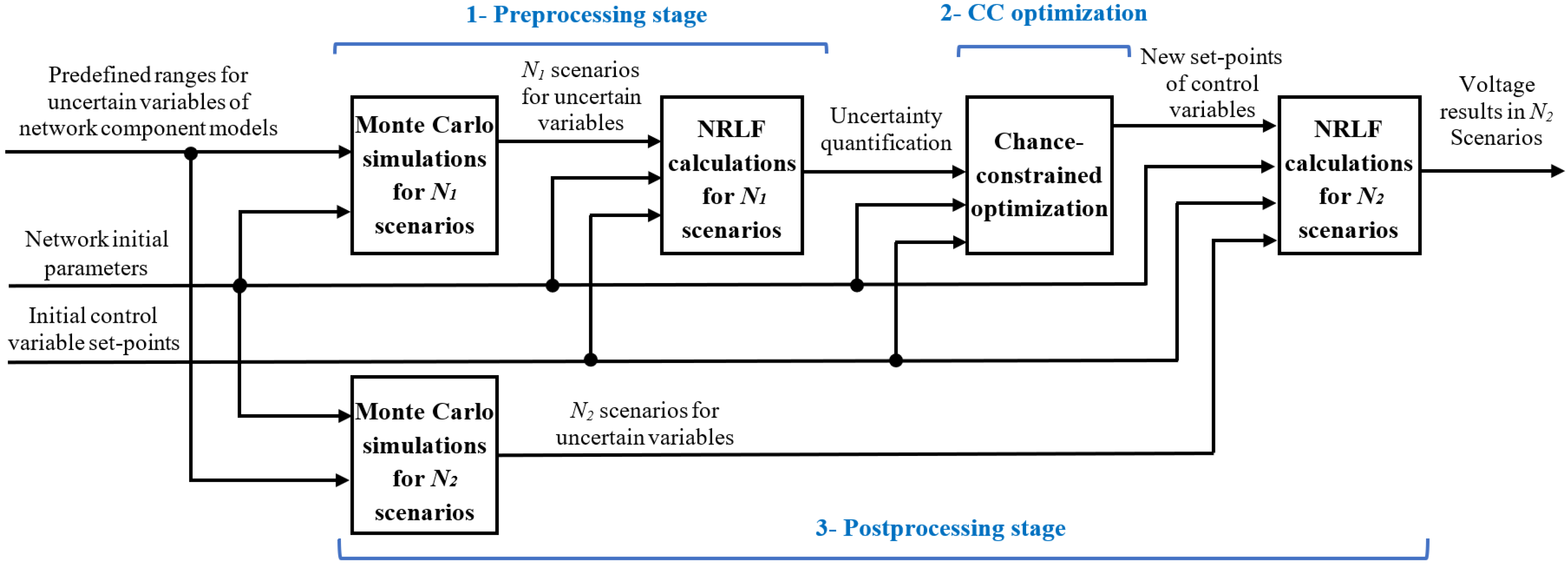
4.1. Preprocessing Stage (Uncertainty Quantification)
In the generic CC formulation, a random variable representing the considered uncertainty is defined according to a distribution function. In our voltage control problem, the uncertainty sources reside in the load, line, and substation transformer models (as explained in
Section 5.2). These mentioned uncertainties have impacts on the LHS and RHS of (6), i.e., the voltage sensitivity coefficients and the required voltage modifications, respectively. However, their impacts are not a priory known. To quantify the uncertainty impacts on (6), we need a preprocessing step that first generates
N1 scenarios for uncertain parameters of network component models, and then evaluates those scenarios with load flow calculations. Doing so allows us to establish the CC voltage control formulation.
Figure 1 presents the proposed framework to perform the CC voltage control task, and to validate the obtained results.
4.2. Formulating the Chance-Constrained Voltage Control Task
As mentioned before, model uncertainties have impacts on the RHS and LHS of (6). However, it is expected that these impacts are significantly higher on the RHS of (6) compared to the LHS. Indeed, the LHS of (6) includes the voltage sensitivity coefficients that give a linearized relationship between small changes in control variables and node voltages. Contrarily, the RHS of (6) is calculated based on the final node voltages according to a given network working point considering whole amounts of nodal load and generation powers. For the sake of simplicity and aiming at preserving the linearity of the original voltage control problem, we assume that the impact of model uncertainty on the LHS of (6) is negligible. It should be noted that we neglect the model uncertainty impacts on the voltage sensitivity coefficients for a given network operating point. If the latter changes, the voltage sensitivity coefficients are accordingly updated in the preprocessing stage of the proposed CC voltage control framework, while they are again considered to be independent of the model uncertainties, in the rest of voltage control procedure. The relevance of this approximation is evaluated in
Section 6.
Disregarding the LHS uncertainties of (6) reduces the final CC voltage control problem to a category having uncertainty only in the RHS, which is mathematically more straightforward to formulate. The CC voltage control problem subject to the RHS uncertainty can be still of the individual or joint type. The respective formulation of mentioned CC categories is detailed below.
In case of the individual CC with the RHS uncertainty, constraint (11) can be simplified as:
The above constraint indicates that the random parameter
must attain a value greater than or equal to
with a probability at least equal to
for
. Mathematically, this is equivalent to impose that the survival function of random variable evaluated at the LHS must be greater than or equal to the confidence level. The survival function is the complement of the cumulative distribution function (CDF) denoted
. In other words, the survival function is equivalent to
. Constraint (12) can be accordingly rewritten as follows [
28].
The above constraint can be simplified to [
28]:
where
stands for the inverse CDF or the quantile function. The constraint (14) is applied to the presented voltage control problem in
Section 2.1. The resulting CC equivalent of constraint (6) (in the deterministic voltage control problem) is given below.
The RHS of (15) is known from the analysis carried out in the preprocessing stage. gives us the required voltage modification to remove the voltage violation at bus u corresponding to the th quantile of the vector of uncertain voltages at bus u. The constraint (15) leads to a joint CC formulation when it is aimed to immunize all the nodes having voltage violations () with a unique risk value . Given the complex coupling of uncertainties in the joint CC voltage control problem, the individual CC formulation is preferred that can guarantee the linearity of the voltage control problem. In this regard, to convert the joint CC voltage control problem to an individual type, two methods are suggested as follows.
CC-Method I: It considers only the bus with the biggest voltage violation in the system as the CC. In this case, we are interested in finding a solution, which is immunized with a probability at least equal to against at the bus with the biggest voltage violation.
CC-Method II: It replaces the unique risk factor of joint CC (
) with a more conservative bound given below according to Bonferroni’s inequality [
28,
29]. As a result, the initial joint CC can be converted to an approximated individual CC with a reduced risk factor equal to
.
In the CC-Method II, we assume that (16) is applied to the bus with the biggest voltage violation at each feeder of the system (to limit the number of individual CC). We evaluate the performance of the abovementioned methods in the context of the voltage control problem subject to model uncertainty in
Section 6.
Overall, the CC voltage control tool has the same objective function and bounds on the control variables as those of the deterministic voltage control approach given by (5) and (7)–(9). The difference of deterministic and CC voltage control methods resides in their voltage constraints. While in the former, the model uncertainty is neglected in (6), the latter considers it via (15). In other words, the resultant individual CC of the (initial joint CC) voltage control problem derived according to CC-Method I and CC-Method II replaces (6) to construct the proposed CC voltage control tool.
4.3. Postprocessing Stage (Result Validation)
The abovementioned CC-based voltage control formulation determines the new set-points of control variables such that the desired level of robustness against model uncertainty can be achieved. In order to verify the latter, complementary analyses are conducted on the obtained set-points of control variables. To this end, Monte Carlo (MC) simulations are performed to generate N2 scenarios for uncertain parameters of the network component models. Load flow studies are then carried out on each of the N2 scenarios considering the new set-points of control variables obtained by the CC-based voltage control and other network data. The obtained nodal voltages in N2 scenarios will be finally analyzed to validate the robustness level of the CC solution in N2 realizations of uncertainties associated with the network component models.
In the preprocessing stage (prior to formulating the CC voltage control problem), when selecting the needed number of scenarios (i.e., N1) for capturing uncertainties and defining their impacts, the requirement regarding the execution time of the voltage control task must be considered. Such a limit does not exist when N2 scenarios are generated to verify the CC results since the corrective decisions have been already taken. Thus, N2 can be much bigger than N1 so that the CC voltage control results can be tested for complementary scenarios that are not necessarily included among N1 scenarios of the preprocessing stage. It should be noted that the defined variation ranges for uncertain parameters of network component models are identical in both preprocessing and postprocessing stages.
6. Simulation Results
The proposed CC voltage control framework presented in
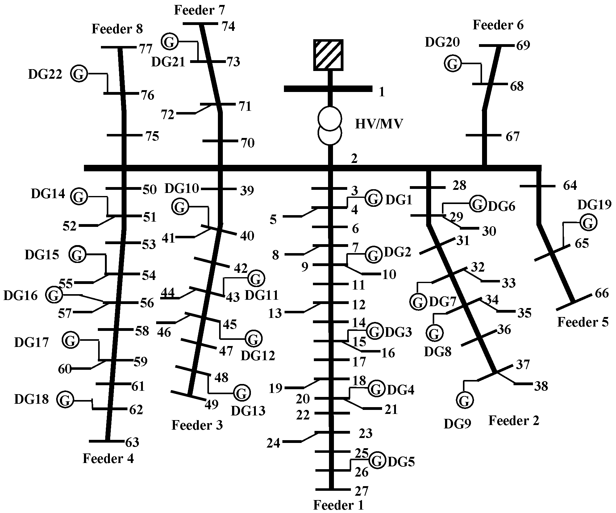
Section 4 is implemented in the MATLAB environment. The performance of the CC voltage control tool is tested on the UKGDS shown in
Figure 2 considering an operating point leading to the voltage rise issues. In the studied working point, it is assumed that the load demands are low (=10% of their nominal values) while the DG active powers are at 90% of their rated values. The selected network operating point constitutes the most difficult voltage management task having the highest possible voltage violations. By validating the performance of the proposed voltage control algorithm on the selected working point, it can be expected that the proposed algorithm would be able to manage other network operating points, having naturally smaller voltage violations.
In order to comply with the constraint regarding the calculation time of the voltage control task, in the preprocessing stage (prior to forming the CC optimization), 500 in-sample scenarios (N1 = 500) are generated by the MC simulations. However, to validate the decisions taken by the CC voltage control tool, the number of out-of-sample scenarios is increased to 5000 (N2 = 5000).
In the voltage control procedure, it is supposed that the transformer tap changer action has the smallest weighting coefficient compared to other control variables that is equal to 1 (CTR = 1) while DG reactive power changes are weighted by a factor which is 50% bigger than the tap changer one (i.e., CQ = 1.5). Also, active power curtailment of DGs is assigned to a coefficient, which is 100% bigger than that of the tap changer (i.e., CP = 2). The (upper) permitted voltage limit is set to 1.03 pu.
6.1. Model Uncertainty Impacts on Node Voltages
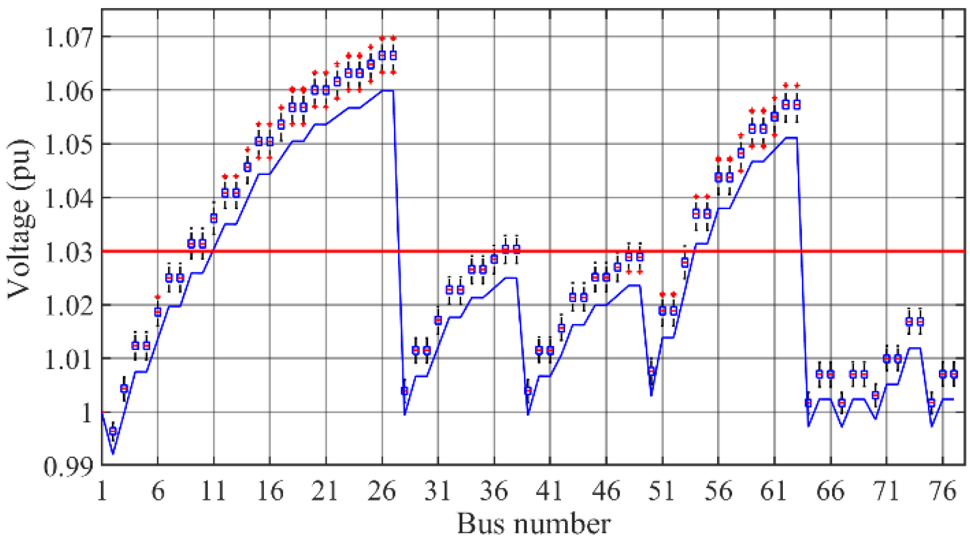
In the first step of our analysis, we are interested to quantify and visualize the impacts of considered sources of model uncertainty on the nodal voltages. To this end, we illustrate in
Figure 3, the boxplots of nodal voltages obtained in the preprocessing stage of the CC framework (presented in
Figure 1) considering
N1 generated scenarios. Besides, to evaluate the possible nodal voltage variations due to model uncertainty impacts with respect to the case neglecting those effects, we present on the same graph in
Figure 3 the node voltages obtained by the deterministic (simplified) network model (which disregards the model uncertainties) with the solid blue line.
As it can be seen in
Figure 3, due to model uncertainty impacts, node voltages can have considerable deviations from their own initial values obtained by the deterministic simplified models (shown with the solid blue line). Precisely, these deviations can reach up to 0.01 pu at bus 26, which contains the biggest voltage violation of the studied system. Clearly, the voltage control algorithm relying on the deterministic simplified models (neglecting the model uncertainty impacts) cannot manage the voltages found within the presented boxplots. This motivates the utilization of the voltage control tool that incorporates the model uncertainty impacts while taking the control decisions.
6.2. Performance Analysis of the Chance-Constrained Voltage Control Framework
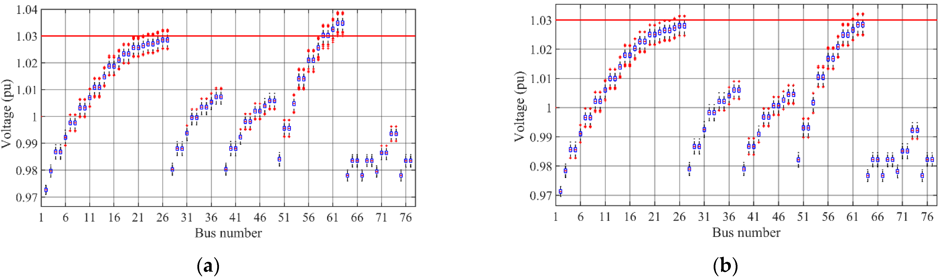
In the second part of this section, we evaluate here the performance of the proposed CC formulation to manage the initial voltages subject to uncertainty (as shown in
Figure 3). Both proposed methods leading to the individual CC formulation (namely, (i) relying on the biggest voltage violation of the system and (ii) based on (16)) are tested here. In the former case, the voltage at bus 26 having the biggest initial voltage violation of the system is modeled as CC. In the latter case, buses 26 and 62 having the biggest voltage violations of their own feeders are considered with CC.
Figure 4 shows the boxplots of nodal voltages obtained in the postprocessing stage of the CC voltage control framework. The desired confidence level is set to 90% (i.e.,
).
In
Figure 4a, one can observe that boxplots of voltages corresponding to buses located at the end of feeder 4 (i.e., buses 62 and 63) are placed outside the permitted voltage range. This means that for every possible realization of uncertainty, there will be a voltage violation at those buses, which is not desirable. It is explained by the fact that in
Figure 4a (corresponding to CC-Method I), the bus with the biggest violation is only considered with CC (i.e., bus 26). Thus, the possible voltage violations in other feeders are not taken into account. Such a problem does not exist in
Figure 4b, where the biggest voltage violation of each feeder is incorporated into the CC voltage control problem according to (16). In order to have a more exact evaluation,
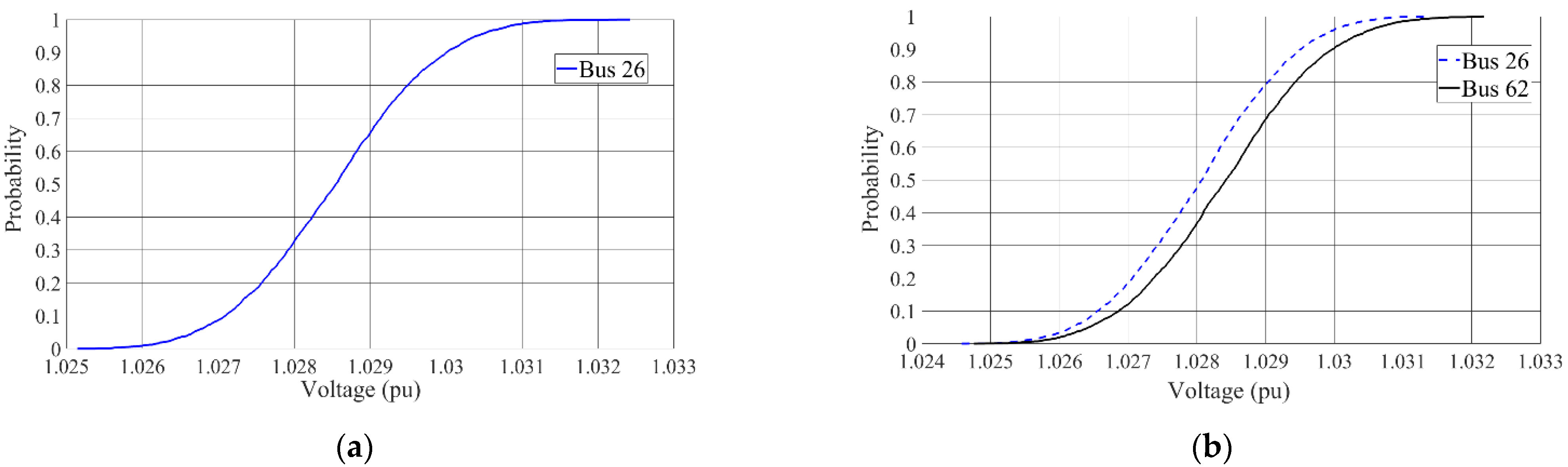
Figure 5 presents the CDF of corrected voltages corresponding to the boxplots shown in
Figure 4 for buses 26 and 62.
In
Figure 5a, it is seen that the 90th quantile of the voltage at bus 26 (corresponding to the node represented with CC) is exactly equal to 1.03 (i.e., the permitted voltage limit). It reveals that the imposed in-sample CC condition to have the confidence level equal to at least 90% at bus 26 is satisfied with a very high accuracy in the out-of-sample evaluation of voltage at bus 26 in the
N2 scenarios of postprocessing stage. This finding also validates the adopted assumption regarding the fact that the impact of model uncertainty on the LHS of (6) is negligible. Indeed, the implemented CC optimization does not consider the uncertainty in the LHS of (6) and its results are quite accurate.
In
Figure 5b, showing the results of CC-Method II where buses 26 and 62 are modelled with CC, it is found that the confidence level of 90% imposed by the CC formulation is respected at those buses, too, but with slightly reduced accuracy at bus 26 compared to the former CC formulation (i.e., Method I).
Table 1 presents the demanded contributions of DG powers and necessary transformer tap movements to manage voltage violations using both above CC methods. In
Table 1 and hereafter, NA indicates that a specific control action is not applied. In addition, DGs with the power changes are only indicated in the table and for the rest of DGs (which are not mentioned), power changes are zero.
In
Table 1, we can see that within both studied CC methods, the tap changer of the substation transformer needs to move (decrease) its position by 4 steps since it has the smallest weighting coefficient (cost). In CC-Method I, the reactive powers of DGs connected to feeder 1 are also changed since the voltage violation at bus 26 is only considered and those DGs have the highest impacts on the voltage at bus 26. In contrast, using CC-Method II, DGs located in feeders 1 and 4 are both employed to manage the CC voltage of buses 26 and 62. It is clearly observed that the CC-Method II requires more control efforts to manage the voltage control problem as it considers the voltage of bus 62, as well. In addition, the approximation and conservatism inherent in (16) can contribute to the increase in objective function of the CC-Method II with respect to that of the CC-Method I. The latter contribution (linked to (16)) is, however, of less importance than the former (relating to considering extra nodes in the CC voltage control problem).
6.3. Comparative Analysis of Chance-Constrained and Robust Voltage Control Approaches
In the last part of this section, we compare the performance of the proposed CC voltage control with that of the robust voltage algorithm (RVCA) developed in [
23] in terms of the conservatism degree of their solutions. Similarly to the proposed CC voltage control framework of this work, the RVCA of [
23] relies on the preprocessing stage for uncertainty quantification, and it employs the sensitivity analysis to linearize the relationships between control variables and node voltages. For the sake of comparison of results, the considered network, models and parameters, initial working point, sensitivity analysis methods, bounds on random parameters, initial conditions, etc., are assumed identical in both CC voltage control tool and RVCA.
Table 2 presents the control variable changes defined by the presented CC voltage control methods for the risk factors equal to 0.2 and 0.05 as well as the RVCA results, which are immunized against the worst realization of uncertainty. In addition,
Table 2 gives the corrective control decisions taken when the model uncertainty impacts are neglected by the so-called deterministic voltage control algorithm (DVCA) presented in (5)–(9).
In
Table 2, one can observe that the smallest objective function corresponds to the DVCA (=6.044) that disregards the model uncertainty impacts by considering the nominal parameters of network component models. From the voltage results shown in
Figure 3, it is, however, known that the response of such a voltage control strategy would not be sufficient to completely remove the voltage violations subject to model uncertainty.
Considering the results obtained by the proposed CC formulations, in
Table 2, it is seen that the CC-Method I (only modeling the node with the worst voltage violation as the CC) leads to smaller objective functions compared to those of the CC-Method II. This finding is in line with the results given in the
Table 1. Indeed, in order to provide the protection against voltage violations in other nodes (feeders) of the system according to (16), the CC-Method II requires more control resources that result in a higher objective function. In addition, in
Table 2, it is noticed that by decreasing the risk factor (
), the objective function of the CC voltage control tool increases to provide the required protection against the uncertainty realization. For instance, using the CC-Method II, the risk factors of 0.2, 0.1, and 0.05 respectively lead to the objective functions equal to 8.661, 8.819, and 8.913. In order to verify the accuracy of corrected voltage results by the proposed CC voltage control techniques,
Table 3 gives the out-of-sample (corrected) voltage values corresponding to the imposed confidence level at buses 26 and 62. The latter buses contain the biggest voltage violations of feeders 1 and 4, respectively.
In
Table 3, we can observe that using the CC-Method I, the imposed confidence level relating to the voltage magnitude at bus 26 (i.e., the bus with the biggest voltage violation of the system) is satisfied with a high accuracy. Indeed, the corrected voltage magnitude at bus 26 corresponding to the imposed confidence level (
) is quite close to the permitted voltage limit (=1.03 pu). However, it is seen that the control actions taken by the CC-Method I cannot manage the voltage rise at bus 62 since the latter bus is not integrated into this CC voltage control formulation. In contrast, the CC-Method II provides the voltage results that are slightly more conservative (arisen from approximation inherent in (16)) but it can handle the voltage violations of both buses 26 and 62 located in feeders 1 and 4, respectively, as can be seen in
Table 3. It should be noted that in
Table 3, the closer the out-of-sample (corrected) voltage results are to the permitted 1.03 pu voltage limit, the more exact the employed CC formulation is.
Finally, by taking into account the RVCA results given in
Table 2 (having the objective function equal to 9.361), it is revealed that the proposed CC voltage control formulations allow us to adjust the robustness level of the voltage control problem through modifying the risk factor (
).
7. Discussion
The simulations carried out in the previous section confirm that the proposed CC voltage control framework can effectively deal with the model uncertainty inherent in the distribution systems. It enables us to adjust the desired confidence level according to which we aim to immunize the voltage control solution subject to uncertainty realizations. While the solution of the voltage control method relying on deterministic simplified models might be insufficient to completely manage the voltage constraints, and on the other hand, the solution of the robust voltage control technique could appear too conservative, the proposed CC framework allows us to find a compromise between the voltage management costs and the conservatism degree. It should be noted that the desired conservatism degree depends not only on the costs of control decisions, but also on the costs associated with the voltage violations. In other words, the optimal risk factor should be determined in accordance with, on the one hand, the costs of corrective control actions, and on the other hand, the voltage violation costs. The more crucial the voltage violation management is, the more justified the price of robustness to pay will be.
The simulation results reveal that the CC-Method I in which the voltage of the bus with the biggest voltage violation is constrained to a confidence level can accurately satisfy the imposed probability condition at that bus, but it cannot address the voltage violations of buses in other feeders of the system. Consequently, the latter method is rather suited for the MV distribution systems with a single feeder. In contrast, the CC-Method II is less accurate (and more conservative), being based on a reduced risk factor (obtained according to (16)), but it can effectively be applied to the distribution systems with multiple feeders.
In this paper, it is also shown that impacts of considered model uncertainty sources on the LHS of voltage constraint (6) (i.e., the voltage sensitivity coefficients) are negligible. Our numerical tests confirm that while being subject to considered model uncertainty sources of this paper, the standard deviation of all sensitivity coefficients in the LHS of (6) does not exceed 0.001 of its respective expected value, which indicates the minor impact of model uncertainties on the voltage sensitivity coefficients. On the contrary, it is demonstrated in
Figure 3 that the model uncertainty can cause considerable deviations in node voltages, and consequently, can change the RHS of (6) with respect to the values obtained by the deterministic network model. These two findings lay the foundation of another important conclusion of this paper, that when the network model is integrated into a voltage control tool to evaluate the initial system state (initial voltages), the model uncertainty can noticeably mislead the voltage control problem analyses, resulting in infeasible or inefficient control decisions. Such a problem inherently applies to a wide range of voltage control techniques developed in the literature [
1,
3,
4,
5,
6,
7,
8,
9,
10,
11,
12,
13,
15,
16,
17,
18,
19,
20,
21,
22,
23,
24]. Contrarily, when a voltage control tool receives the initial voltages based on the real voltage measurements (and not from a state estimation interface or a load flow study relying on the simplified network model), the model uncertainty impacts on the voltage control problem would be of a minor importance since the uncertainty in initial node voltages (or uncertainty in the RHS of (6)) is removed thanks to the voltage measurements. In the literature, examples of such a voltage control scheme relying on real measurements, like [
2], are scarce.
8. Conclusions
A chance-constrained (CC) framework is developed in this paper to deal with the model uncertainty impacts inherent in the voltage control problem of MV distribution systems. Relying on the linearized formulation of the voltage control problem with the voltage sensitivity analysis, its CC counterpart is derived by incorporating uncertainty impacts into the former formulation. The voltage control problem under model uncertainty, consequently, is formulated as a joint CC optimization with right-hand side (RHS) uncertainty. Aiming at preserving the linearity of the original formulation, two methods are proposed to decompose the complex joint couplings of the RHS uncertainties. The developed CC formulations are finally tested on the 77-bus, 11 kV radial distribution system. The simulation results confirm the accuracy of the confidence level expected from both CC formulations. Furthermore, comparative analysis of the CC-based voltage control framework having different risk factors and the voltage control method based on the robust optimization reveals that the proposed CC framework allows us to adjust the robustness level of solutions to find a compromise between the voltage management costs and the desired conservatism level.
Another main finding of this paper relates to the fact that the model uncertainty impacts are of a great importance when calculating the initial system state (initial voltages), while they have minor effects on the voltage sensitivity coefficients. Consequently, the model uncertainty effects can be neglected if a voltage control scheme works based on the real voltage measurements. Otherwise, defining the system state (initial voltages) based on the simplified deterministic models would mislead the voltage control decisions.


