Article

Virtual Inertia Coordinated Allocation Method Considering Inertia Demand and Wind Turbine Inertia Response Capability

1
School of Electrical Engineering, Shanghai University of Electric Power, Shanghai 200090, China
2
Wenzhou Power Supply Company, State Grid Zhejiang Electric Power Co., Ltd., Wenzhou 325000, China
*
Author to whom correspondence should be addressed.
Energies 2021, 14(16), 5002; https://doi.org/10.3390/en14165002
Submission received: 7 June 2021 / Revised: 20 July 2021 / Accepted: 9 August 2021 / Published: 15 August 2021
(This article belongs to the Section B2: Clean Energy)

Abstract

:
Wind turbines can have inertia characteristics similar to synchronous generators through virtual inertia control, which helps to provide the inertia support for the system. However, there is the problem of how to coordinate the allocation of virtual inertia among wind turbines. In response to this problem, this paper first analyzes the inertia response capabilities of wind turbines and puts forward an evaluation index that quantifies the inertia response capability of wind turbines. The inertia response capability of a wind farm is evaluated at the entire system level. Based on the evaluation index, the virtual inertia coordinated allocation method considers the system inertia demand and the inertia response capabilities of the wind turbines. It is proposed to release the inertia response capability of each wind turbine while avoiding an excessive release of kinetic energy and bring a second impact by wind turbines’ exiting operation. Finally, the effectiveness of the proposed method is verified by a simulation case study.

1. Introduction

The inertia of a power system is of great significance to the frequency stability of the power grid, and it has resistance to system frequency changes caused by disturbances. The inertia can prevent sudden changes in the system frequency and is the basic guarantee for the safe and stable operation of the system [1].
With the increase in the penetration rate of wind power in power systems, traditional synchronous generators are gradually being replaced by wind turbines, resulting in a continuous reduction in the inertia in the system, and the frequency stability of power systems is facing a huge threat [2].
In order to enable wind turbines to provide inertia support to the system as with traditional synchronous generators, virtual inertia control can be used to increase active power quickly when the system is disturbed [3].
When the system is disturbed, the additional active power that can be issued by wind turbines and the releasable rotor kinetic energy are different. However, conventional virtual inertia control does not consider the wind turbine’s own inertia response capability and inertia allocation [4,5,6,7]. If the virtual inertia is evenly allocated to all wind turbines, the inertia response of each unit is exactly the same, which will cause some units to excessively release the rotor kinetic energy and exit the operation, while the inertia response capability of other units is not fully utilized [8]. Therefore, it is necessary to study a new method of coordinated allocation of virtual inertia according to the inertia response capability of the wind turbine.
In [9], it was pointed out that a wind turbine can release the kinetic energy of the rotor through fast active power control, and the size and duration of the frequency regulation power can affect the frequency response of the system, but the study failed to provide an optimization method for frequency control. In [10,11,12], a method of adding frequency control to the wind turbine was proposed to improve the frequency response capability of the system, but it does not consider the problem of its own frequency regulation capability and the virtual inertia allocation among the wind turbines. The frequency regulation capability of wind turbines based on the speed and capacity limit of the wind turbines and determining the virtual inertia of a single wind turbine were analyzed in [13], but the study did not provide a quantitative expression of the wind turbine inertia response capability and did not consider the inertia allocation between the wind turbines. In [14], virtual inertia control was realized at the over-speed point, and the study provided the tuning method for control adjustment. Coordinated control avoids the frequency drop, but the release of the inertia response capability of the wind turbine is limited. In [15], a method of the real-time active power control strategy for wind farms based on the ordering of wind turbine control capabilities was proposed. However, this method requires wind power prediction, which is affected by the accuracy of the prediction, has greater uncertainty, and does not consider the inertia demand of the system. A quantitative analysis of the frequency regulation capability of a single wind turbine was conducted in [16], and a self-coordinated frequency control method for wind turbines was proposed based on the frequency modulation capability of the wind turbine. However, this method only considers the operating status of the wind turbine itself. The frequency coordination control still needs to be further studied.
Current research mostly focuses on the coordinated control of wind turbines participating in primary frequency modulation, and the research on the inertia response capability of wind turbines is relatively lacking. Therefore, in view of the current deficiencies in the virtual inertia allocation of wind turbines, this paper studies a doubly fed induction generator (DFIG), introduces the inertia response capability evaluation index of wind turbines, and quantitatively evaluates the inertia response capability of a single wind turbine. Additionally, the inertia response capability of wind power at the whole system level is studied. A wind turbine inertia coordinated allocation method is proposed considering both the system inertia demand and the wind turbines’ own inertia response capability. Finally, in the modified IEEE39-node simulation system, the effectiveness of the proposed method is verified.
This paper is organized as follows: Section 2 analyzes the inertia response capability of wind turbines. Section 3 introduces the inertia response capability evaluation index of wind turbines. In Section 4, a method of virtual inertia allocation based on the inertia response capability evaluation index is proposed. The effectiveness of the proposed method of virtual inertia allocation is verified in Section 5. Conclusions are drawn in Section 6.

2. Analysis of Inertia Response Capability of Wind Turbines

2.1. Virtual Inertia Control of Wind Turbines

Wind turbines participate in the inertia response through a virtual inertia control that introduces a frequency change rate to adjust the active power output of the wind turbines. With virtual control, wind turbines can suppress sudden changes in the system frequency, play a role similar to the moment of inertia of synchronous generators, and increase the effective inertia of the power system [17].
Similar to a synchronous generator, the inertia response process of a wind turbine can be expressed by the swing equation [18].
2 H W d ω d t = P m P e   or   2 H W d f d t = P m P e
where H W is the virtual inertia time constant of the wind turbine in seconds; ω is the angular velocity of the rotor in p.u.; f is the frequency in p.u.; P m is the input mechanical power in p.u.; P e is the output electromagnetic power in p.u.
It can be seen from Equation (1) that when the active power of the wind turbine participating in the inertia response increases, the virtual inertia time constant will increase. Therefore, the virtual inertia time constant can reflect the supporting power of the wind turbine participating in the inertia response.

2.2. Virtual Inertia Time Constant of Wind Turbines

Wind turbines use virtual inertia control to change the output electromagnetic power during disturbances. Due to virtual inertia control, the electromagnetic power and mechanical power of the wind turbine are no longer equal, meaning the wind turbine releases or absorbs the rotational kinetic energy contained in its rotating parts, provides active power support to the system, and maintains the frequency stability [19]. When the system frequency drops, the kinetic energy of the i-th wind turbine is released. The inertia response process can be expressed by the change in the rotor speed and the inherent moment of inertia:
Δ E W i = 1 2 J W i ( ω 2 ω 0 2 )
where J W i , ω 0 , and ω are the i-th wind turbine inherent moment of inertia, initial rotor angular velocity, and current rotor angular velocity, respectively.
Then, the active power support of the additional output of the wind turbine during the inertia response process is
Δ P e i = d Δ E W i d t = J W i ω d ω d t
Substituting Equation (3) into Equation (1), during the inertia response process, Δ P m = 0 , we can obtain
H W i = Δ P e i 2 d f d t = J W i ω d ω d t 2 d f d t
where H W i is the virtual inertia time constant of the i-th wind turbine. It can be seen from Equation (4) that when subjected to the same disturbance, the virtual inertia time constant of the wind turbine is positively correlated with the speed and the rate of change in the speed.

3. Evaluation of the Inertia Response Capability of Wind Turbines

By passing over the blades, wind produces lift and then induces a rotational torque. The available power in the wind is
P max = 0.5 C p ρ π R 2 υ 3
where R is the blade radius, ρ is the air density, υ is the wind speed, and C p is called the power coefficient of the wind turbine that expresses the aerodynamic efficiency of the turbine and is affected by the pitch angle of the blades.
Inertial response emulation typically provides fast increases (or decreases) in the power production through sudden increases (or decreases) in the generator torque.
When wind turbines provide system inertia support, the difference in the inertia response capabilities of different operating states should be considered to maximize their inertia response capabilities.

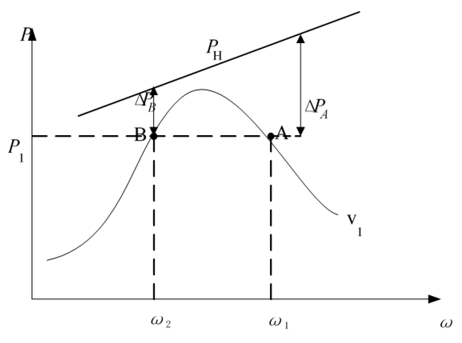
3.1. Comparison of Inertia Response Capability of Wind Turbines under Different Working Conditions

The power tracking curves of DFIG at the wind speeds are shown in Figure 1 [20]. Due to the limitation of the maximum torque of the converter, the wind turbine can only output PH when participating in the inertia response. It can be seen from Figure 1 that under the same wind speed v1, the active power output of point A and point B is the same, but the wind turbine angular velocity of point A is greater than that of point B. From Equation (4), the virtual inertia time constant of point A is greater than the virtual inertia time of point B. The inertia response capability of point A is greater than the inertia response capability of point B.

3.2. Evaluation Index of Wind Turbine Inertia Response Capability

In order to evaluate the inertia response capability of wind turbines in different operating states, it is necessary to quantitatively express the inertia response capability of the wind turbines. Combined with the above analysis, the inertia response capability evaluation index K is defined as
{ K = k ω k P = ω 2 ω min 2 ω n 2 P H P P H P L k ω = ω 2 ω min 2 ω n 2 k P = P H P P H P L
where k ω is the kinetic energy factor; k P is the power increase capability factor; ω is the current speed of the wind turbine; ω min is the lowest operating speed of the wind turbine; ω n is the rated speed of the wind turbine; P is the current active power of the wind turbine; P H and P L are the upper and lower limits of the output power, respectively, which are additional power for inertial response emulation.
The kinetic energy factor k ω reflects the amount of kinetic energy stored in the rotor of the wind turbine. The greater the speed, the greater the stored rotational kinetic energy and the greater the kinetic energy factor.
Despite the high speed of wind turbines in the high-speed area, wind turbines also have capacity limitations. The higher the wind speed, the closer the output power of the wind turbines to the output power limit, and the less power that can be issued at the moment of the inertia response.
In order to fully consider the impact of the instantaneous additional power in the evaluation of the inertia response capability of wind turbines, the inertia response capability evaluation index K introduces the power increase capability factor k P . In response to the moment of inertia, the wind turbine can instantaneously increase the amount of active power. The greater k P , the greater the instantaneous additional power. When the rotation speed is the same, the rotor speed change rate d ω d t is also greater. Therefore, the inertia response capability evaluation index K proposed in this paper can reflect the inertia response capability of wind turbines.

4. Wind Turbine Virtual Inertia Allocation

This section first analyzes the minimum inertia required by the system and determines whether wind turbines need to participate in the inertia response. According to the evaluation index of the inertia response, the virtual inertia is initially allocated and adjusted for wind turbines in different operating states, in order to fully release its inertia response capability. At the same time, the excessive release of kinetic energy is avoided by the wind turbine with a low inertia response capability, resulting in tripping the operation, and causing a secondary impact on the system frequency.

4.1. System Minimum Inertia Requirement

The inertia time constant of the system H S can be calculated from the parameters of the synchronous generators and wind turbines in the system:
H S = j = 1 N SG H SG , j S SG , j + i = 1 N W H W , i S W , i S total
where H S is the inertia time constant of the system; H SG , j is the inertia time constant of the j-th synchronous generator; H W , i is the virtual inertia time constant of the i-th wind turbine; S SG , j and S W , i are the corresponding synchronous generators and wind turbine rated capacities, respectively; N SG and N W are the numbers of synchronous generators and wind turbines in the system; S total is the total capacity of synchronous generators and wind turbines, namely,
S total = j = 1 N SG S SG , j + i = 1 N W S W , i
In order to ensure the frequency stability, the total inertia of the system should not be less than the minimum inertia required by the system, meaning
H S H min
where H min is the minimum inertia required by the system. Substituting Equation (7) into Equation (9), the inertia that the wind turbines need to provide is
i = 1 N W H W , i S W , i H min S total j = 1 N SG H SG , j S SG , j

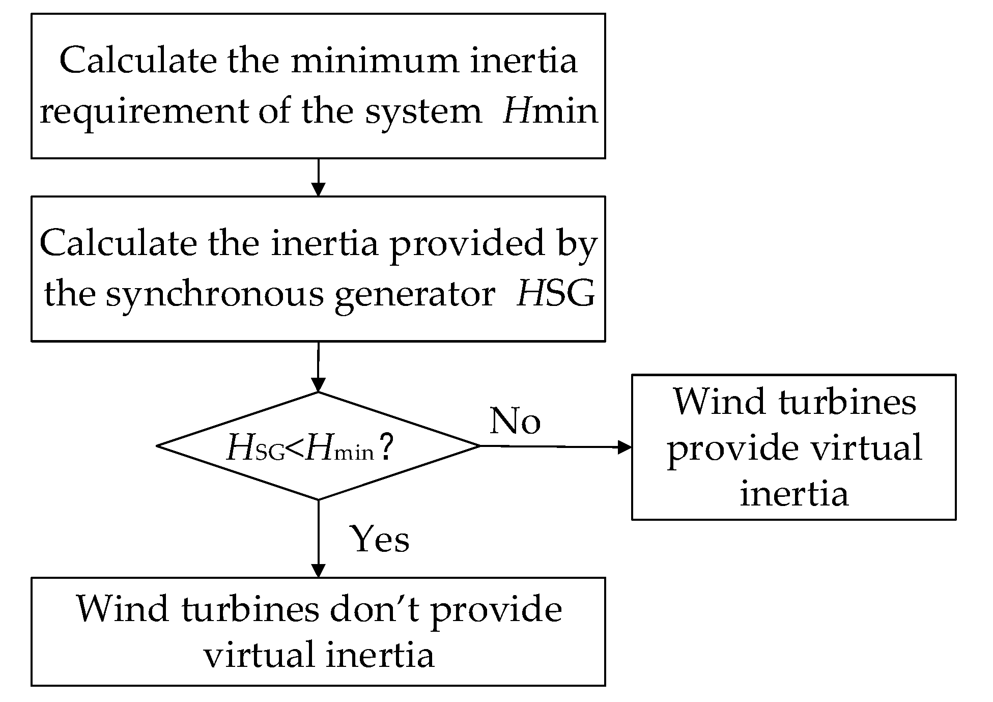
4.2. Decisions of Wind Turbine Participation in Inertia Response

Frequency fluctuations caused by small disturbances in the system occur frequently, such as small load switching and transformer taps. If wind turbines change their speed frequently in order to participate in the system inertia response, their service life will be reduced [21,22,23].
In order to avoid the above situation, first, whether the wind turbines in the system need to participate in the inertia response is determined. The inertia provided by the synchronous generator in the system is
H SG = j = 1 N SG H SG , j S SG , j S total
Then, it needs to be determined whether the inertia provided by the synchronous generator meets the minimum inertia requirement of the system under the disturbance. If H SG H min , the wind turbines are not required to provide virtual inertia; if H SG < H min , the wind turbines are required to provide virtual inertia. This process is shown in Figure 2.

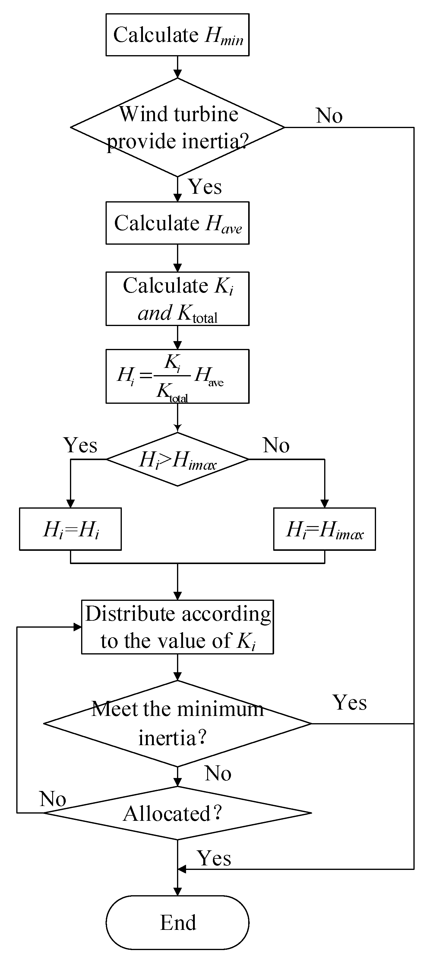
4.3. Preliminary Allocation of Virtual Inertia of Wind Turbines

When the wind turbines participate in the inertia response and the wind turbine is increased from the minimum output power to the maximum output power,
Δ P = Δ P lim = P H P L
At this time, the virtual inertia time constant of the wind turbine is the limit of the inertia time constant that the wind turbine can provide:
H W lim = Δ P lim 2 d f d t = P H P L 2 d f d t
Under this disturbance, the wind turbine with the current output power of P participates in the inertia response, the additional power is increased to P max , and the virtual inertia time constant at this time is
H Wmax = P H P 2 d f d t = P H P P H P L P H P L 2 d f d t = k P H W lim
Similar to a synchronous generator, the product of the rated capacity of the wind turbine P n and the virtual inertia time constant H W represents the rotational kinetic energy stored by the wind turbine at the rated speed, namely,
E Kn = P n H W = Δ E K max
The actual running wind turbine participates in the inertia response, and the kinetic energy released when the speed drops to ω min is
Δ E K = E K E K min = ω 2 ω min 2 ω n 2 0 Δ E K max = k ω P n H W
Substituting Equations (6) and (14) into Equation (16), we obtain
Δ E K = k ω P n k P H W lim = K P n H W lim
From a system perspective, the total kinetic energy released by the inertia response of wind turbines is the sum of the kinetic energy released by each wind turbine. Then, the evaluation index of the inertia response capability of wind power K total is
K total = i = 1 N W K i P n , i H W lim , i i = 1 N W P n , i H W lim , i
where K i is the evaluation index of the inertia response capability of the i-th wind turbine in the system, and its value is determined by Equation (6); P n , i is the rated power of the i-th wind turbine in the system; H W lim , i is the limit of the inertia time constant of the i-th unit in the wind farm under the disturbance; N W is the number of wind turbines in the system.
In particular, when the parameters of the wind turbines in the system are equal, through Equation (18), we can obtain
K total = 1 N W i = 1 N w K i
According to Equation (10), it can be found that the average inertia time constant for each wind turbine in the system under the disturbance should be
H ave = H min S total j = 1 N SG H SG , j S SG , j i = 1 N W S W , i
Considering the inertia response capabilities of different wind turbines, the virtual inertia time constant of each wind turbine participating in the inertia response is
H i = K i K total H ave
According to (21), H i is assigned to the corresponding wind turbine inertia time constant in turn. If the current total inertia satisfies Equation (9), the remaining wind turbines in the system will no longer provide an inertia response. The initial allocation process of wind turbine inertia is shown in Figure 3.

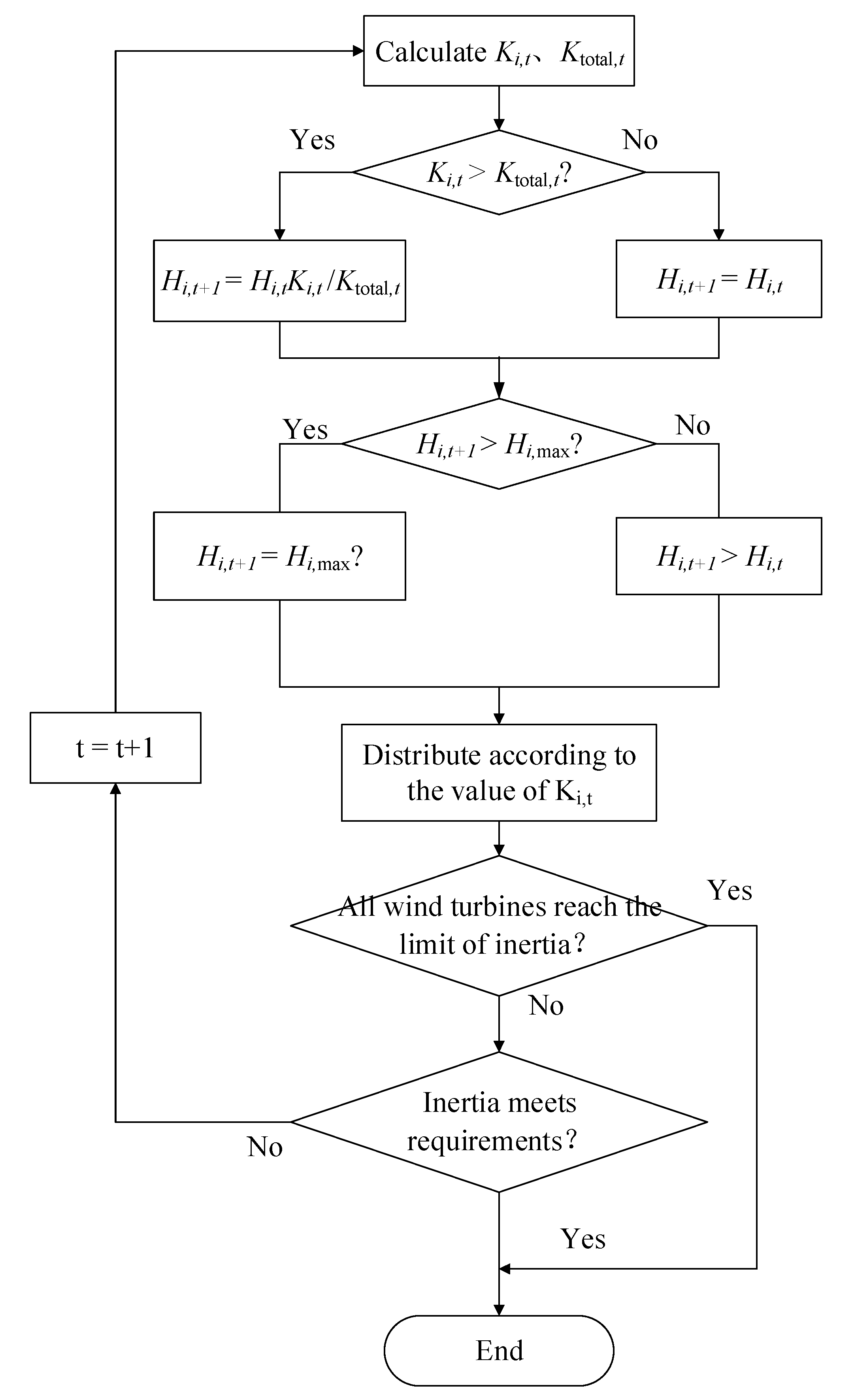
4.4. Wind Turbine Virtual Inertia Adjustment

If the minimum inertia requirement of the system is still not satisfied after the first round of wind turbine inertia allocation, the inertia response capability evaluation and correction need to be carried out on the basis of the first round of virtual inertia allocation. After the inertia is allocated, it assumes that the wind turbine generates additional active power. Then, the inertia response capability evaluation index K i , t of each wind turbine can be calculated according to Equation (6), K total , t is calculated according to Equation (18), and, finally, the inertia time constant of wind turbines is corrected according to Equation (22).
{ H i , t + 1 = K i , t K total , t H i , t , K i , t K total , t > 1 H i , t + 1 = H i , t , K i , t K total , t 1
where H i , t + 1 and H i , t are the inertial time constants allocated for t+1 and t of the i-th wind turbine in the system; K i . t and K total , t are the evaluation index of the inertial response capability of the i-th wind turbine for t and the evaluation index of the wind power inertial response capability at the field level of the system, respectively. If H i , t H i max , then let H i , t = H i max .
Continue the process of the above-mentioned inertia response capability evaluation, inertia allocation, and inertia time constant correction until the minimum inertia requirement of the system is met, or the virtual inertia provided by all wind turbines in the system reaches its maximum value. The process of wind turbine inertia adjustment is shown in Figure 4.

5. Simulation Analysis

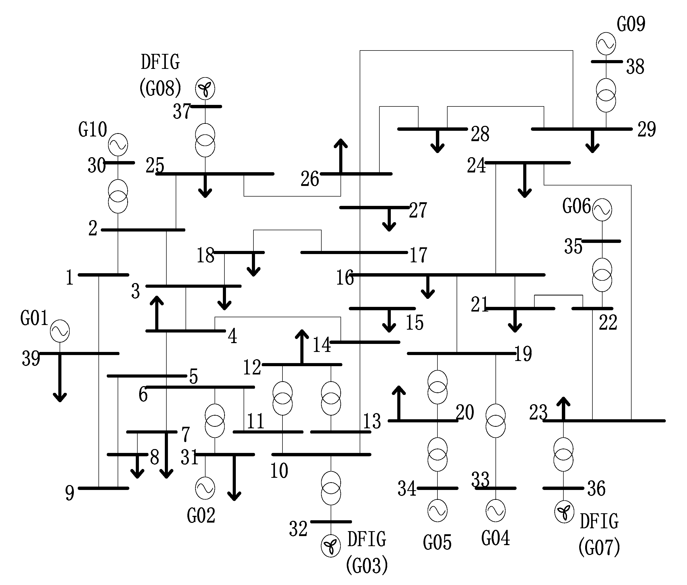
5.1. Simulation System

A modified IEEE 39-bus New England system was built as shown in Figure 5 [24]. The main parameters are shown in Table 1. The frequency of this model was set to 60 Hz. In the simulation system, G03, G07, and G08 are wind farms, which are composed of 130 DFIGs, 112 DFIGs, and 108 DFIGs, respectively. The rated capacity of a single DFIG is 1.67 MVA, and the rated output power is 1.5 MW. The speed of each wind turbine in the system is shown in Table 2. The load shedding in Table 2 is the percentage reduction in the output power of the wind turbine relative to the output power running in the MPPT mode at the wind speed. Since the output power of the wind turbines in the low-wind speed area is relatively small, no over-speed reduction was performed.

5.2. Inertia Allocation

The evaluation index K of the inertia response capability of each wind turbine in the system is determined according to Equation (6) and is shown in Figure 6. When the speed is lower than 0.7 p.u., the wind turbines do not participate in the inertia response, meaning K is zero. It can be seen from Figure 6 that the inertia response capability of the wind turbines in the middle-wind speed zone is the strongest, and the inertia response capability of the wind turbines in the low-wind speed zone is the weakest. In addition, the inertia response improvement obtained by over-speed load shedding in the medium-wind speed zone is higher than that in the high-wind speed zone. Since the parameters of each wind turbine set in the simulation system are the same, it can be obtained from Equation (19) that K total = 0.2529 .
At t = 30   s , the system load is increased by 600 MW. According to [25], in order to keep the ROCOF from exceeding 0.5 Hz/s the minimum inertia requires 30 GW·s. The inertia provided by the synchronous generator in the simulation system was 24.62 GW·s, so the wind turbines needed to provide the left 5.38 GW·s of inertia. According to Equation (20), the average inertia time constant of each wind turbine can be obtained. According to Equation (21), the virtual inertia time constant of each wind turbine is assigned, as shown in Table 3.
Thus all wind turbines with inertia response capability participate in the system inertia response and provide 5.398 GW·s of inertia to the system to meet the minimum inertia demand of the system.
When the virtual inertia allocation method is used in all wind turbines, Figure 7 shows the ROCOF of each node because of a sudden load increase of 600 MW. The ROCOF at node 20 is the largest, 0.4995 Hz/s, which is slightly less than 0.5 Hz/s. That meets the minimum inertia requirement of the system.

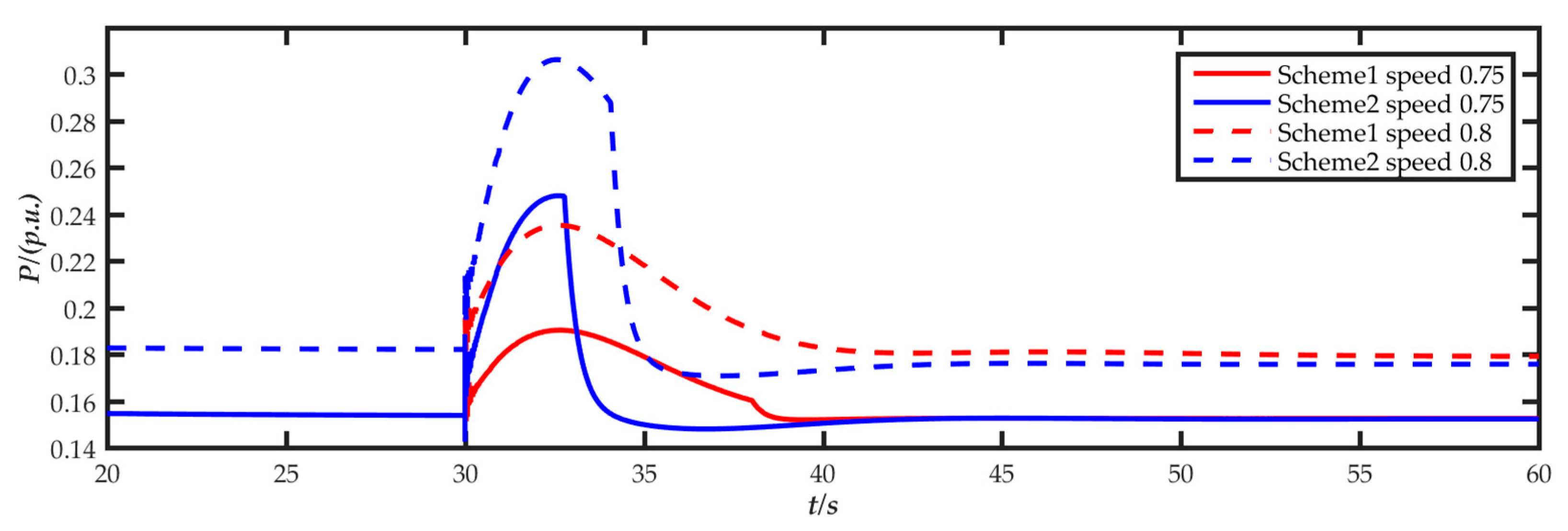
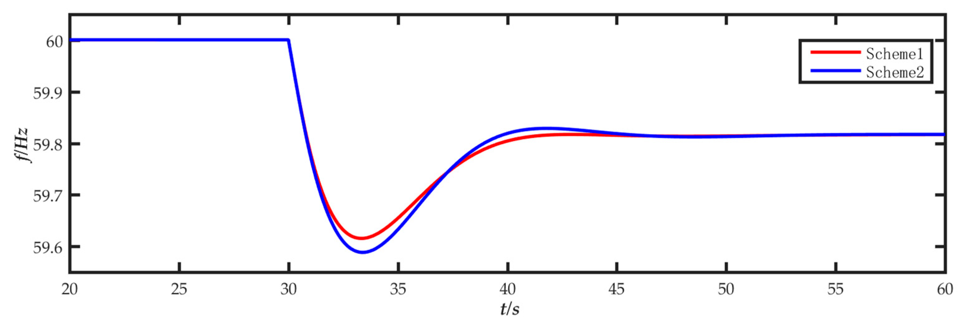
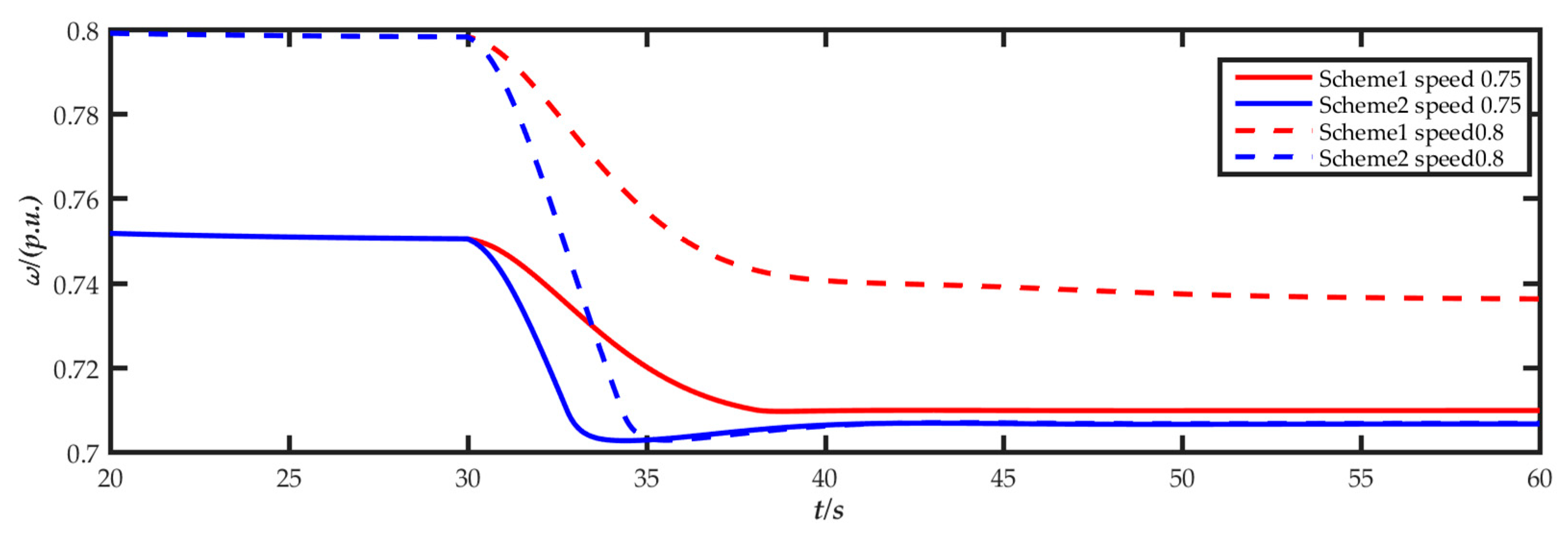
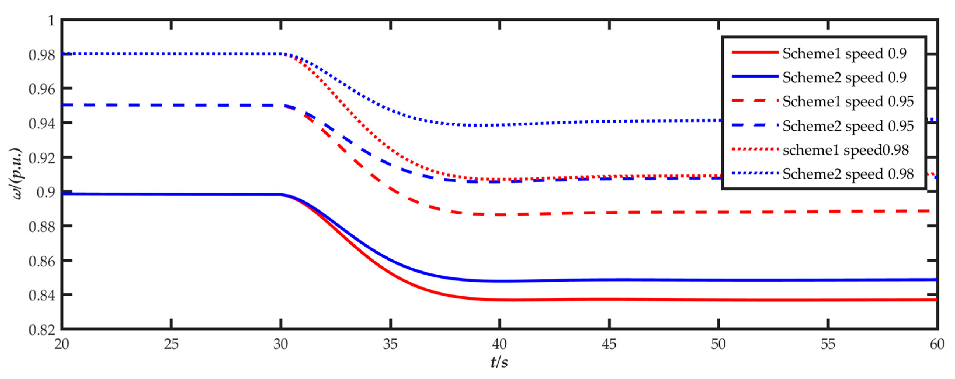
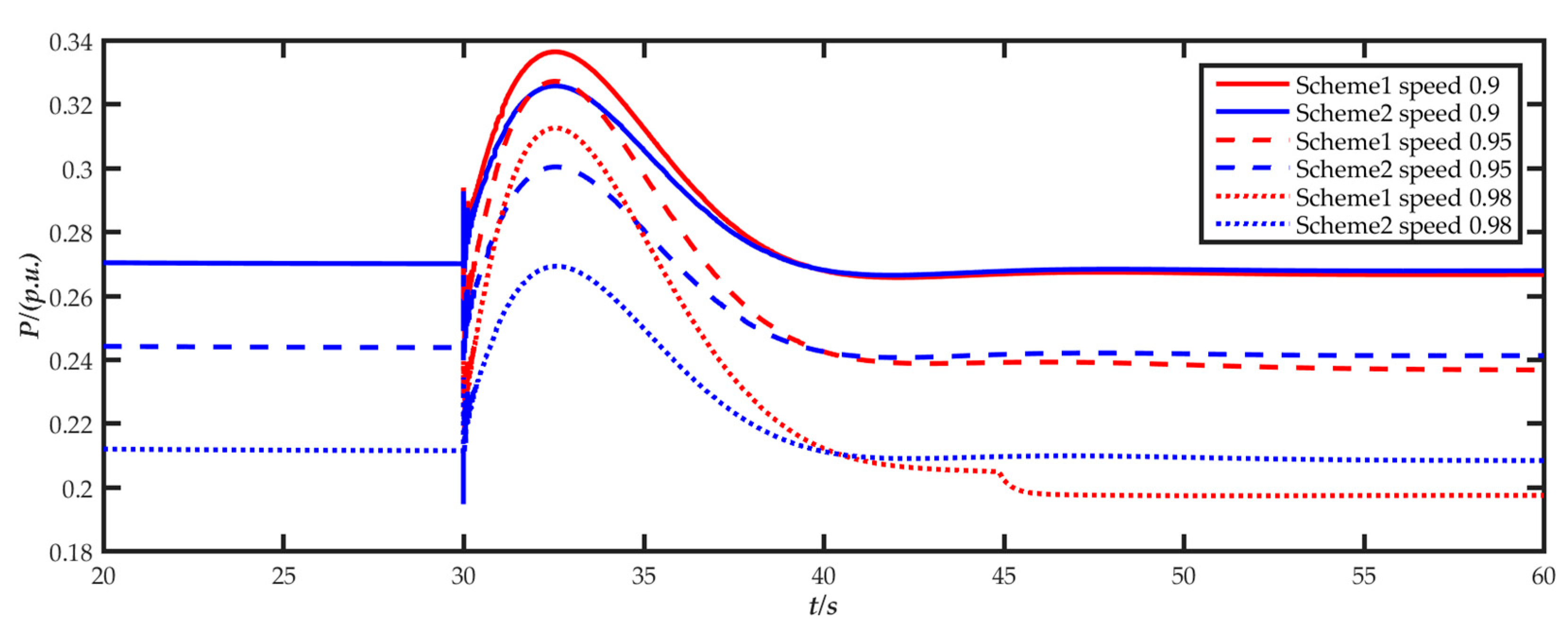
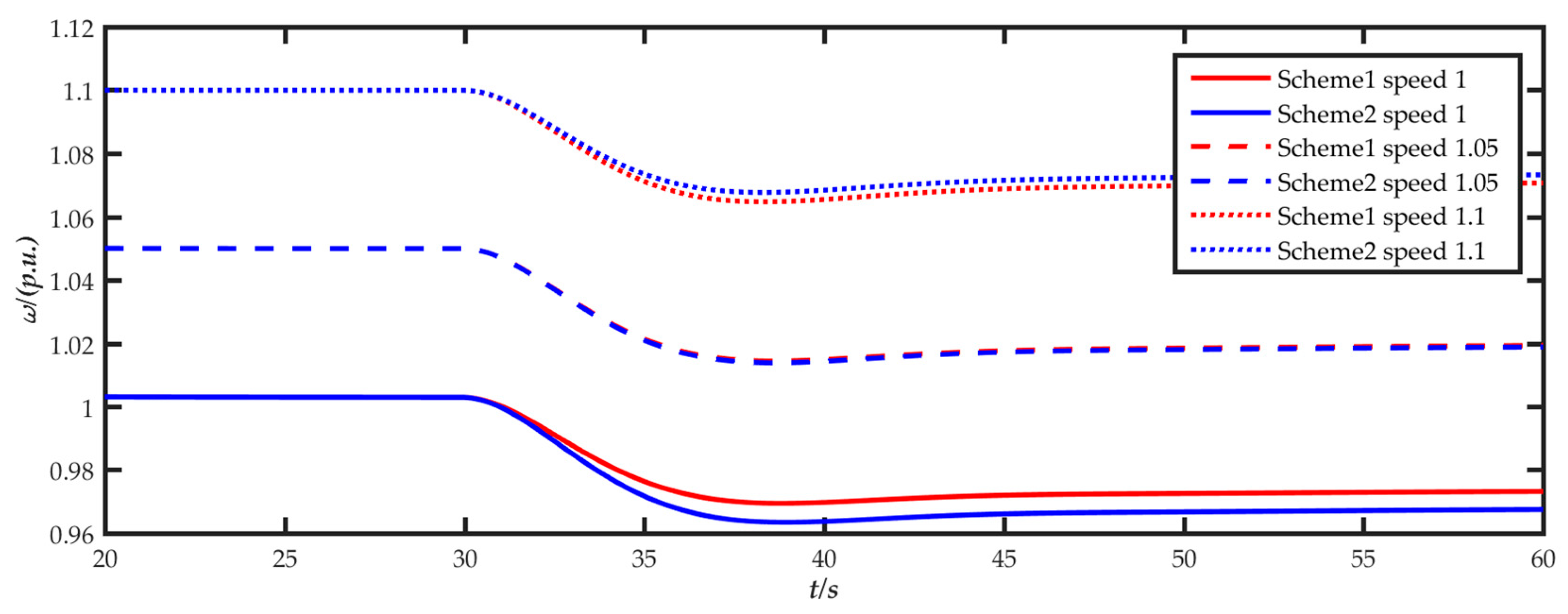
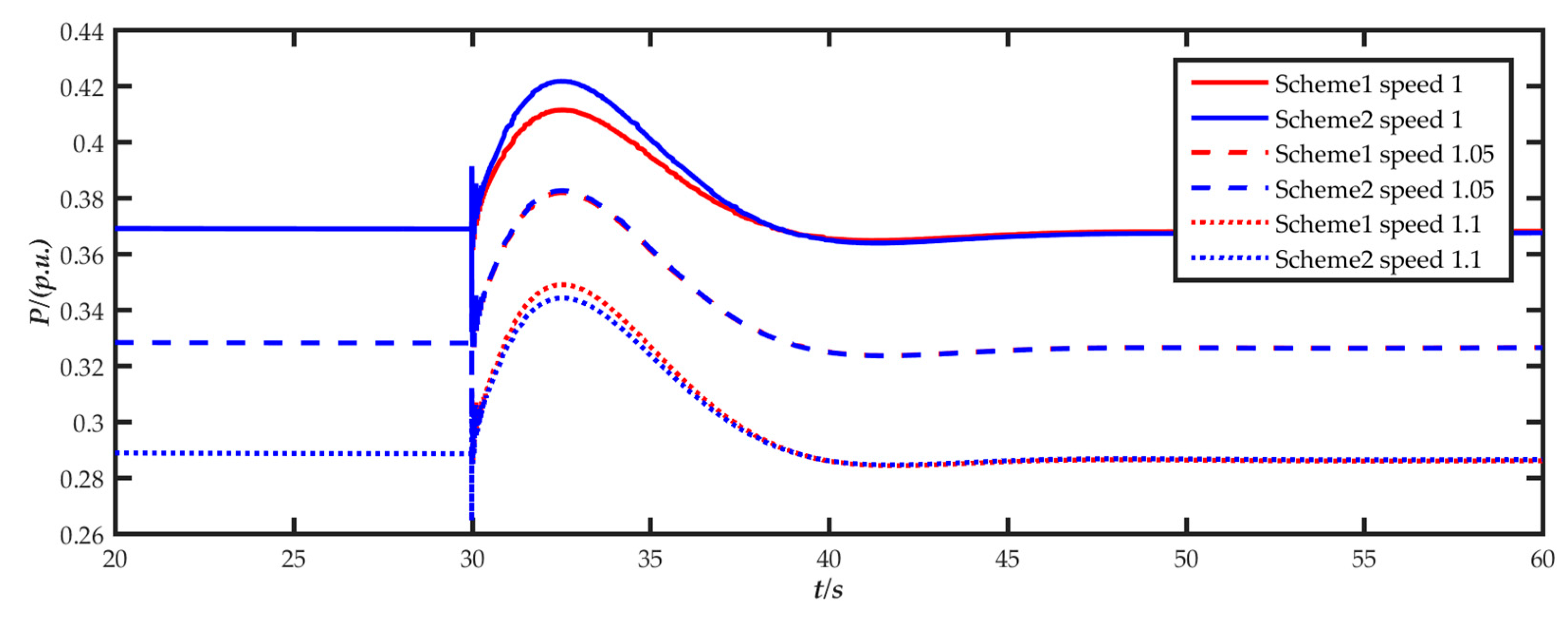
5.3. Comparative Analysis of Inertia Allocation

The proposed wind turbine virtual inertia allocation method (Scheme 1) was compared with the average allocation method (Scheme 2). Parameters of the two schemes were set as follows:
(1)
Scheme 1: The virtual inertia coordinated allocation scheme proposed in this paper;
(2)
Scheme 2: Even allocation. Regardless of their own inertia response capability, the virtual inertia time constant of each wind turbines is set to 10.1 s.
According to the above two allocation schemes, the frequency change in the simulation system is shown in Figure 8. In the two cases, the inertia provided by the wind turbine to the system is 5.398 GW·s and 5.38 GW·s respectively. The values are almost the same. However, the frequency drop in Scheme 2 is even greater. The reason is that Scheme 2 does not consider the lower kinetic energy of the wind turbines in the low-wind speed zone, resulting in an excessive inertia response output in the low-wind speed zone. Then the speed quickly drops to 0.7 p.u. and the wind turbine exits the inertia response process. In the process of the frequency drop, it causes a secondary impact on the grid frequency. Scheme 1 considers the coordinated allocation of virtual inertia between wind turbines with different inertia response capabilities, allowing wind turbines with strong inertia response capabilities in the midium-wind speed zone to undertake more inertia response responsibilities.
Figure 9, Figure 10, Figure 11, Figure 12, Figure 13 and Figure 14 show the speed and power changes in the wind turbines in the low-, medium-, and high-wind speed zones during the inertia response process. It can be seen from the figures that before the frequency reaches the lowest point the wind turbines in the low-wind speed zone of Scheme 2 excessively release kinetic energy and exit the inertia response prematurely, which brings a secondary impact to the system frequency. In Scheme 1, the inertia allocation is based on the inertia response capability of the wind turbines themselves. Compared with Scheme 2, the inertia provided by the wind turbines in the low-wind speed region is reduced, but the inertia provided by the wind turbines in the medium-wind speed region is significantly increased, and the inertia of the wind turbine in the high-wind speed region is equivalent. This allows the wind turbines in the medium-wind speed zone with the highest inertia response capability to undertake more inertia support tasks and release more kinetic energy to compensate for the decrease in the kinetic energy released by the wind turbines in the low-wind speed zone, in order to prevent the lower-speed wind turbines from reaching the lower speed limit and prematurely exiting the inertia response process. Additionally, this improves the inertia support effect of the wind turbines while avoiding the secondary impact on the system frequency.

6. Conclusions

This paper analyzed the characteristics of virtual inertia control of doubly fed wind turbines, quantified and evaluated the inertia response capability of wind turbines through the wind turbine inertia response capability evaluation index K, and proposed a coordinated allocation method of the virtual inertia of wind turbines that combines the system inertia demand and the wind turbine inertia response capability.
(1)
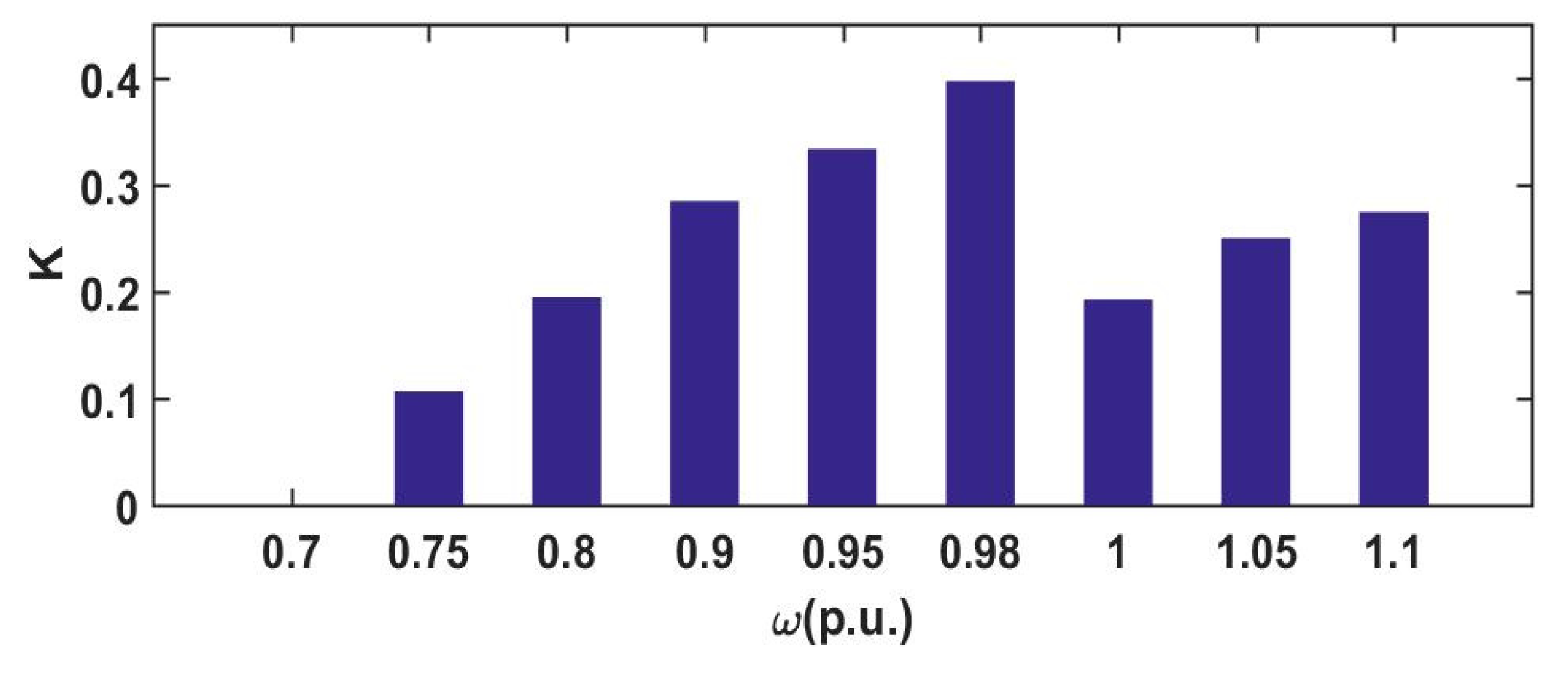
In order to express the inertia response capability of wind turbines in different operating states, this paper proposed the inertia response capability evaluation index K, which comprehensively considered the rotor kinetic energy storage and the wind turbines output power limitation.
(2)
Through the inertia response capability evaluation index K, the inertia response capability of wind turbines in the medium-wind speed zone was the strongest, followed by the high-wind speed zone, and the low-wind speed zone was the weakest. In addition, the inertia response improvement in wind turbines in the medium-wind speed zone by over-speed load shedding was higher than that of wind turbines in the high-wind speed zone.
(3)
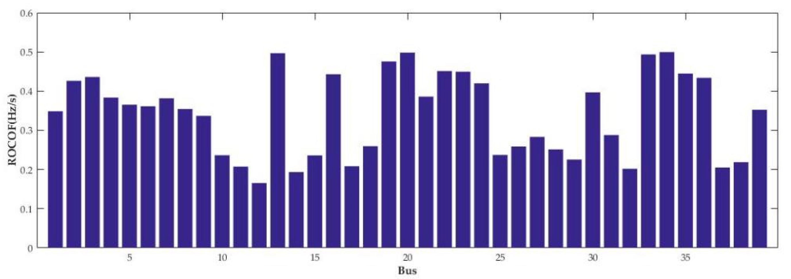
Based on the inertia response capability evaluation index K, considering the system requirements and the wind turbines’ own inertia response capability, this paper proposed the virtual inertia coordinated allocation method, and the simulation verified the effectiveness of the method.

Author Contributions

Conceptualization, B.X.; methodology, B.X., L.Z.; software, B.X.; validation, L.Z., X.Y., Y.Y. (Yinxin Yang); formal analysis, B.X., L.Z.; writing—original draft preparation, B.X., L.Z., Y.Y. (Yin Yao); writing—review and editing, B.X., Y.Y. (Yin Yao); supervision, B.X.; project administration, D.L. All authors have read and agreed to the published version of the manuscript.

Funding

This research was funded by the National Natural Science Foundation of China, grant number 51977128, and the Science and Technology Commission of Shanghai Municipality, grant number 17020500800.2.

Conflicts of Interest

The authors declare no conflict of interest.

References

  1. Sun, H.D.; Wang, B.C.; Li, W.F.; Yang, C.; Wei, W. Research on inertia system of frequency response for power system with high penetration electronics. Proc. CSEE 2020, 40, 5179–5192. [Google Scholar]
  2. Wang, B.; Yang, D.Y.; Cai, G.W. Review of research on power system inertia related issues in the context of high penetration of renewable power generation. Power Syst. Technol. 2020, 44, 2998–3007. [Google Scholar]
  3. Zhang, X.; Chen, Y.L.; Yue, S.; Zha, X.B.; Zhang, D.Y.; Xue, L. Retrospect and Prospect of Research on Frequency Regulation Technology of Power System by Wind Power. Power Syst. Technol. 2018, 42, 1793–1803. [Google Scholar]
  4. Lan, F.; Pan, Y.F.; Shi, M.; Li, J.H. Optimal Variable-coefficient Virtual Inertia Control for DFIG-based Wind Turbines. Autom. Electr. Power Syst. 2019, 43, 51–61. [Google Scholar]
  5. Ke, X.B.; Zhang, W.C.; Li, P.W.; Niu, S.B.; Sheng, S.Q.; Yang, J.W. Fuzzy Adaptive Virtual Inertia Control for High Wind Power Penetration System. Power Syst. Technol. 2020, 44, 2127–2136. [Google Scholar]
  6. Altin, M.; Hansen, A.D.; Barlas, T.K.; Das, K.; Sakamurl, J.N. Optimization of Short-term Overproduction Response of Variable Speed Wind Turbines. IEEE Trans. Sustain. Energy 2018, 9, 1732–1739. [Google Scholar] [CrossRef]
  7. Attya, A.B.; Dominguez-Garcia, J.L.; Anaya-Lara, O. A review on frequency support provision by wind power plants: Current and future challenges. Renew. Sustain. Energy Rev. 2018, 81, 2071–2087. [Google Scholar] [CrossRef] [Green Version]
  8. Yang, D.J.; Kim, J.; Kang, Y.C.; Muljadl, E.; Zhang, N.; Hong, J.; Song, S.H.; Zheng, T.Y. Temporary Frequency Support of a DFIG for High Wind Power Penetration. IEEE Trans. Power Syst. 2018, 33, 3428–3437. [Google Scholar] [CrossRef]
  9. Keung, P.K.; Li, P.; Bannakar, H.; Ooi, B.T. Kinetic energy of wind-turbine generators for system frequency support. IEEE Trans. Power Syst. 2009, 24, 279–287. [Google Scholar] [CrossRef]
  10. Li, S.L.; Wang, W.S.; Zhang, X.; Qin, S.Y.; Xie, Z.; Wang, R.M. Impact of wind power on power system frequency and combined virtual inertia control. Autom. Electr. Power Syst. 2019, 43, 64–73. [Google Scholar]
  11. Li, S.C.; Huang, Y.H.; Wang, L.Y.; Lei, X.L.; Tang, H.Y.; Deng, C.H. Modeling Primary Frequency Regulation Auxiliary Control System of Doubly Fed Induction Generator Based on Rotor Speed Control. Proc. CSEE 2017, 37, 7077–7089. [Google Scholar]
  12. Wang, X.D.; Li, K.K.; Lu, S.X.; Liu, Y.M. Virtual Synchronous Generrator Based Virtual Inertial Control Strategy of Wind Turbine. Acta Energ. Sol. Sin. 2018, 39, 1418–1425. [Google Scholar]
  13. Ding, L.; Yin, S.Y.; Wang, T.X.; Jiang, J.P.; Cheng, F.M.; Si, J.C. Integrated Frequency Control Strategy of DFIGs Based on Virtual Inertia and Over-Speed Control. Power Syst. Technol. 2015, 39, 2385–2391. [Google Scholar]
  14. Chen, Y.H.; Wang, G.; Shi, Q.M.; Fu, L.J.; Jiang, W.T.; Huang, H. A New Coordinated Virtual Inertia Control Strategy for Wind Farms. Autom. Electr. Power Syst. 2015, 39, 27–33. [Google Scholar]
  15. Deng, H.M.; Tang, L.L.; Wu, X.G.; Qiao, Y.; Liu, F. Active power control strategy of wind farms based on wind turbine regulation ability ranking. Power Syst. Technol. 2018, 42, 2577–2584. [Google Scholar]
  16. Shi, Q.; Wang, G.; Ma, W.; Fu, L.; Wu, L.; Xing, P. Coordinated virtual inertia control strategy for D-PMSG considering frequency regulation ability. J. Electr. Eng. Technol. 2016, 11, 1921–1935. [Google Scholar] [CrossRef] [Green Version]
  17. Li, S.L.; Qin, S.Y.; Wang, R.M.; Zhang, L.; Bi, R. A collaborative control of primary frequency regulation for DFIG-WT. Acta Energ. Sol. Sin. 2020, 41, 101–109. [Google Scholar]
  18. Kundur, P. Power System Stability and Control; McGraw-Hill Professional: New York, NY, USA, 1994; pp. 128–136. [Google Scholar]
  19. Liu, B.B.; Yang, J.W.; Liao, K.; He, Z.Y. Improved Frequency control strategy for DFIG-based wind turbines based on rotor kinetic energy control. Autom. Electr. Power Syst. 2016, 40, 17–22. [Google Scholar]
  20. Ghosh, S.; Kamalasadan, S.; Senroy, N.; Enslin, J. Doubly fed induction generator(DFIG)-based wind farm control framework for primary frequency and inertial response application. IEEE Trans. Power Syst. 2016, 31, 1861–1871. [Google Scholar] [CrossRef]
  21. Tang, X.S.; Miao, F.F.; Qi, Z.P.; He, H.M.; Wu, T.; Li, S.Y. Survey on frequency control of wind power. Proc. CSEE 2014, 34, 4304–4314. [Google Scholar]
  22. Fu, Y.S.; Sang, D.; Cao, W.; Zhang, Z.; Zhang, J. REserviceS project of EU and it’s enlightenment to China’s wind power and PV participation in grid frequency regulation. Power Syst. Technol. 2019, 43, 613–621. [Google Scholar]
  23. Liu, Y.; Shao, G.H.; Zhang, H.P.; Wang, C.Y. Analysis of renewable energy participation in primary frequency regulation and parameter setting scheme of power grid. Power Syst. Technol. 2020, 44, 683–689. [Google Scholar]
  24. Li, D.D.; Zhang, J.L.; Xu, B.; Zhao, Y.; Yang, F. Equivalent Inertia Assessment in Renewable Power System Considering Properties of Distributed Frequency. Power Syst. Technol. 2020, 44, 2913–2921. [Google Scholar]
  25. Gu, H.J.; Yan, R.F.; Saha, T.K. Minimum Synchronous Inertia Requirement of Renewable Power Systems. IEEE Trans. Power Syst. 2018, 33, 1533–1543. [Google Scholar] [CrossRef] [Green Version]
Figure 1. Power tracking curve of DFIG at different wind speeds.
Energies 14 05002 g001
Figure 2. Decision of whether the wind turbines participate in the inertia response.
Energies 14 05002 g002
Figure 3. Flow chart of preliminary wind turbine inertia allocation.
Energies 14 05002 g003
Figure 4. Flow chart of wind turbine inertia adjustment.
Energies 14 05002 g004
Figure 5. The modified IEEE 39-bus New England system.
Energies 14 05002 g005
Figure 6. Evaluation index of wind turbines’ inertia response capability.
Energies 14 05002 g006
Figure 7. Rate of change in frequency of each node.
Energies 14 05002 g007
Figure 8. Frequency change in the system.
Energies 14 05002 g008
Figure 9. Speed change in wind turbines in the low-wind speed zone.
Energies 14 05002 g009
Figure 10. Power change in wind turbines in the low-wind speed zone.
Energies 14 05002 g010
Figure 11. Speed change in wind turbines in the medium-wind speed zone.
Energies 14 05002 g011
Figure 12. Power change in wind turbines in the medium-wind speed zone.
Energies 14 05002 g012
Figure 13. Speed change in wind turbines in the high-wind speed zone.
Energies 14 05002 g013
Figure 14. Power change in wind turbines in the high-wind speed zone.
Energies 14 05002 g014
Table 1. Simulation parameters.
GeneratorSN/MVAH/sInertia/GW·s
G01100055
G0210003.033.03
G0410002.862.86
G0510002.602.60
G0610003.483.48
G0910003.453.45
G1010004.204.20
Table 2. Wind turbine speed settings.
Wind SpeedWind Farmω/p.u.Load SheddingNumber
Low-wind speed zoneG070.7030
0.75042
0.8040
Medium-wind speed zoneG030.9035
0.9510%52
0.9820%43
High-wind speed zoneG081060
1.0510%15
1.122%33
Table 3. Allocation of virtual inertia of wind turbines.
Wind Farmω/p.u.NumberKH/sInertia /GW·s
G070.730000
0.75420.10644.250.298
0.8400.19477.780.52
G030.9350.284311.350.66
0.95520.333313.311.16
0.98430.396715.851.14
G081600.19247.680.77
1.05150.24969.970.25
1.1330.274010.940.60
Publisher’s Note: MDPI stays neutral with regard to jurisdictional claims in published maps and institutional affiliations.

