
Potential of Slip Synchronous Wind Turbine Systems: Grid Support and Mechanical Load Mitigation


Abstract
:1. Introduction
2. Dynamic Stability of Direct Grid-Connected PMSG WTS
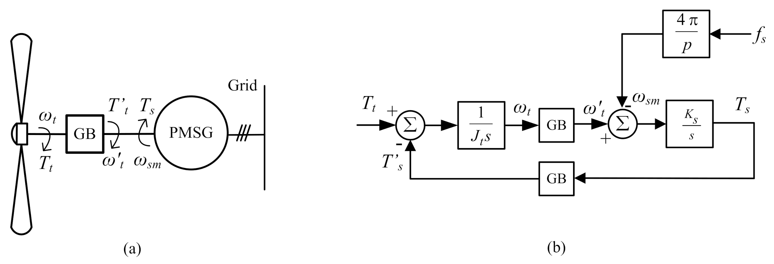
2.1. Direct Grid-Connected PMSG
2.2. Direct Grid-Connected SS-PMSG
3. Modelling
3.1. Grid Model
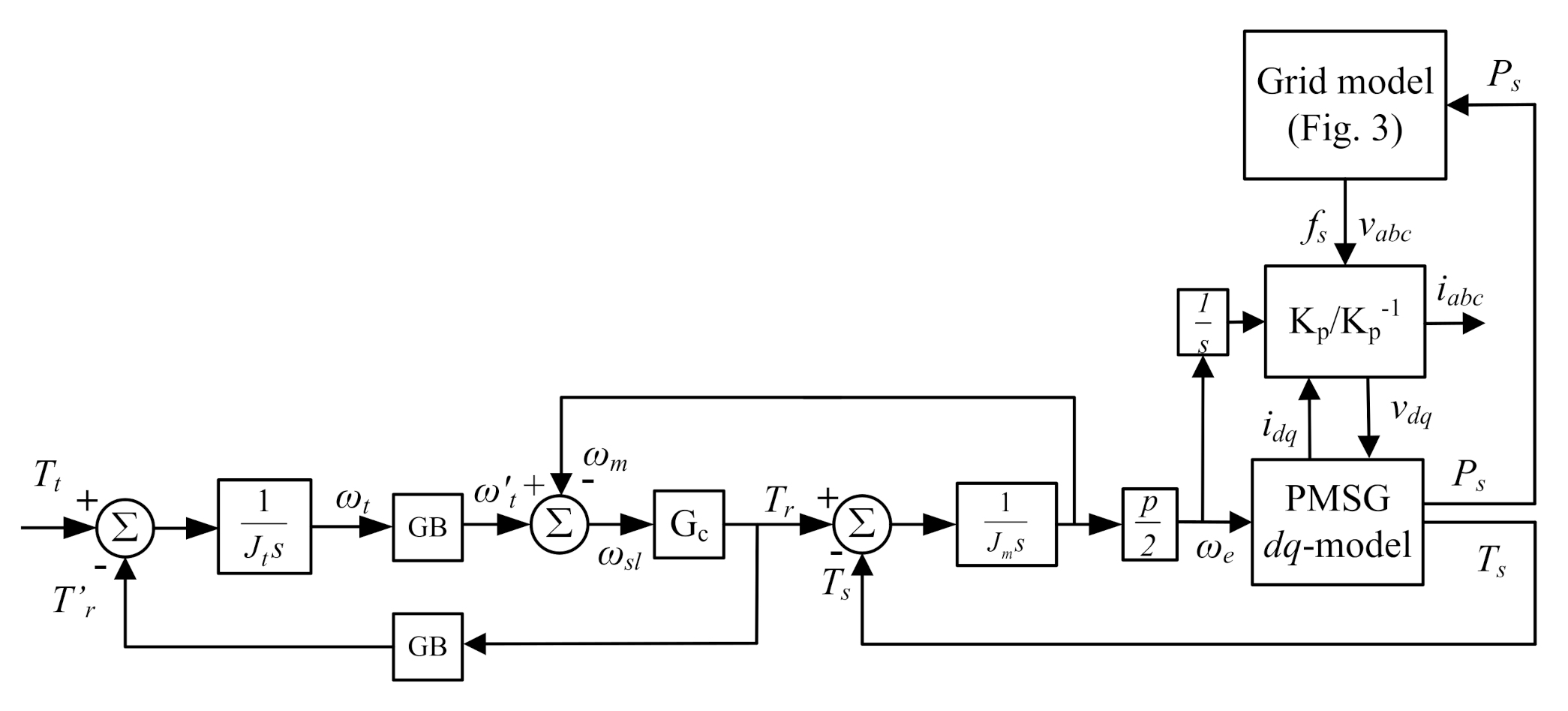
3.2. SS-WTS Model
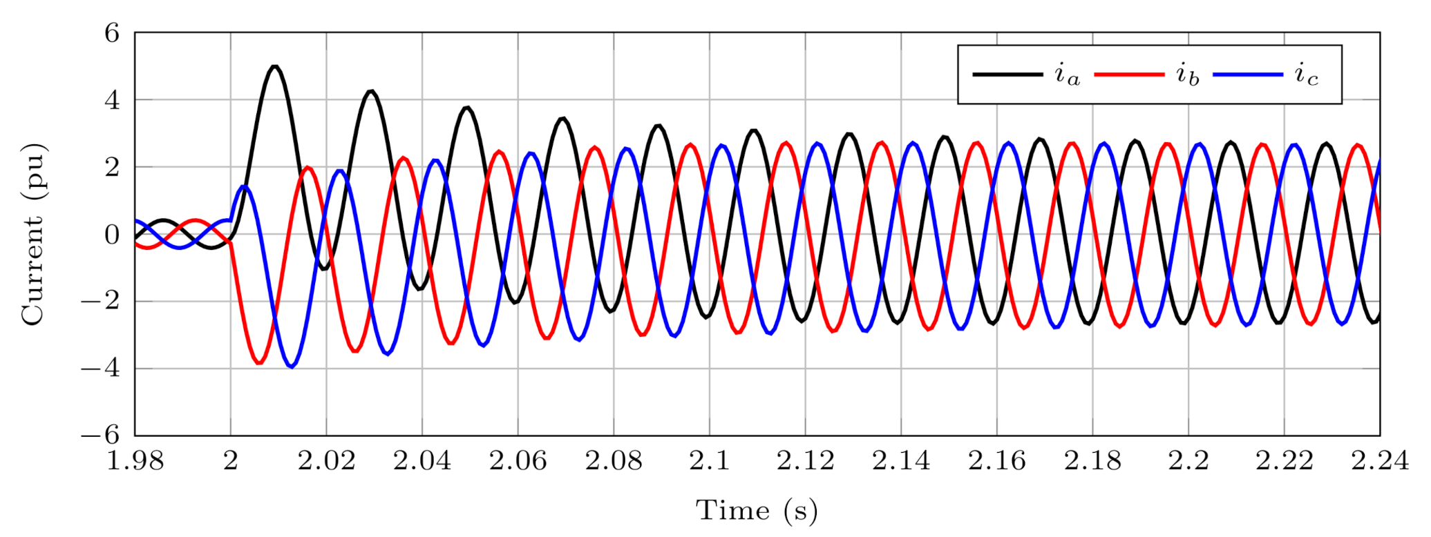
3.3. PMSG under Short-Circuit Conditions
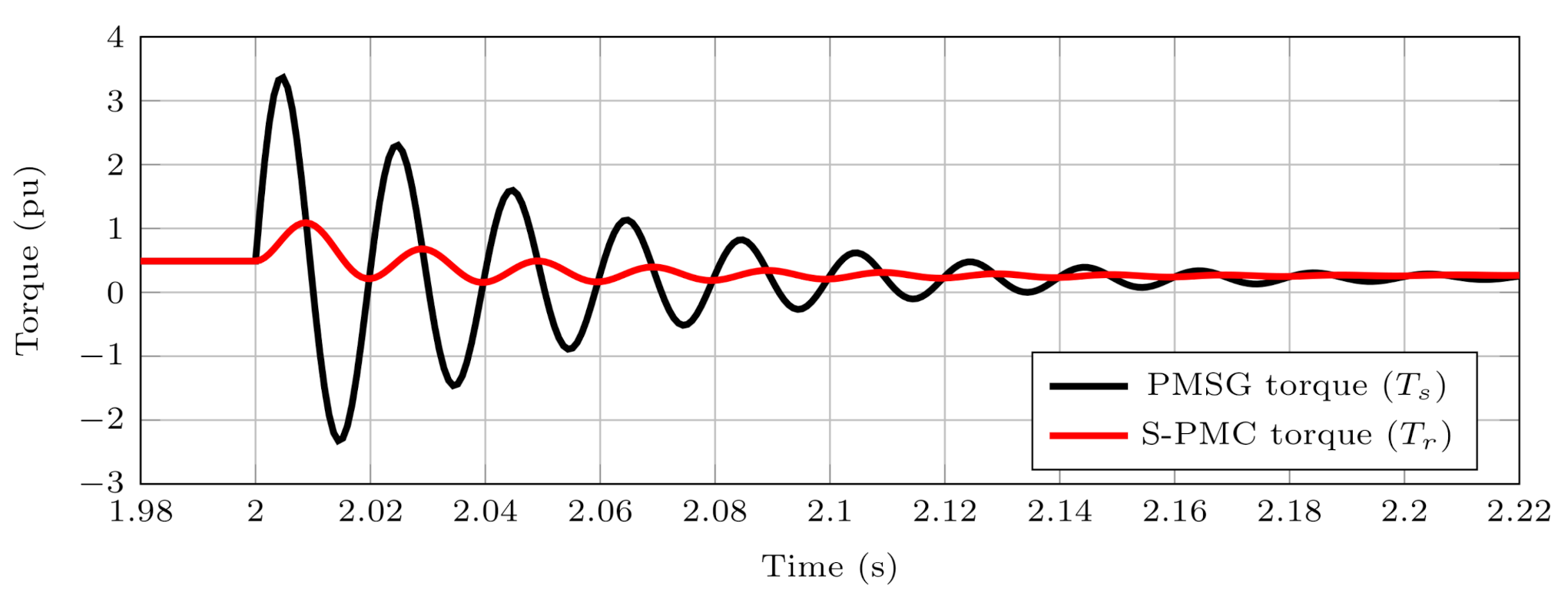
3.4. Torque-Damping Effect of the S-PMC and PMSG
4. Simulation Results
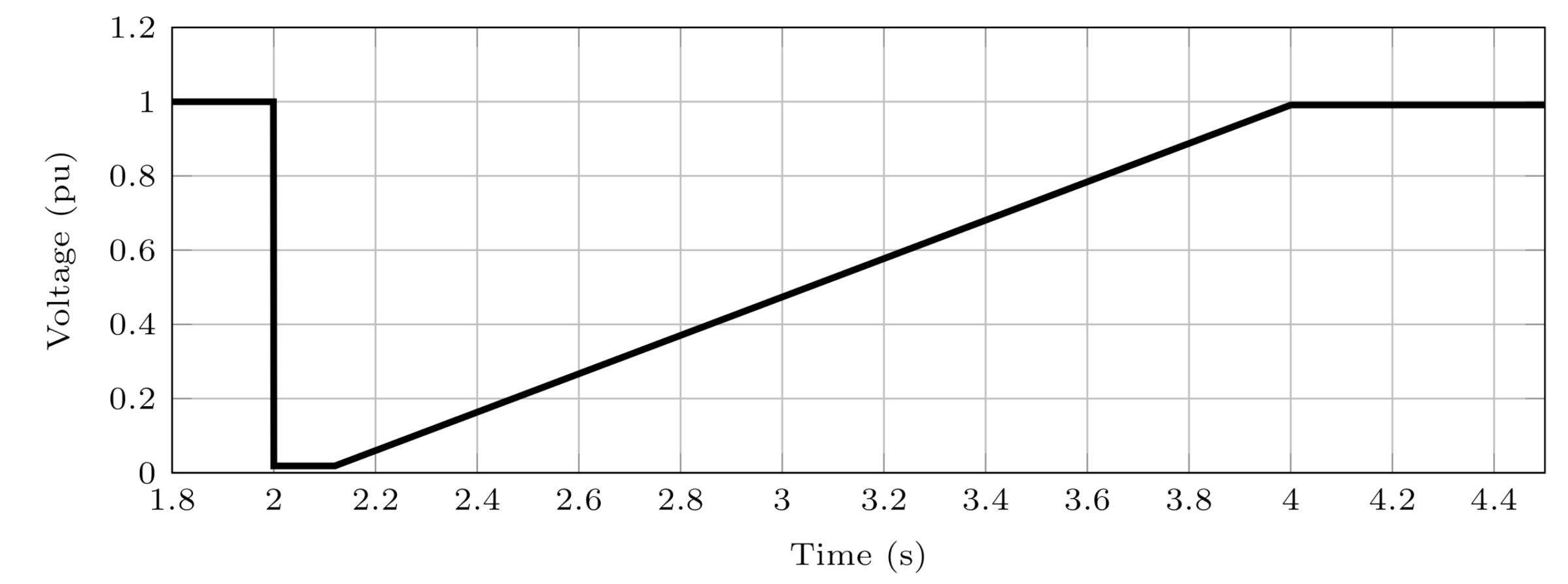
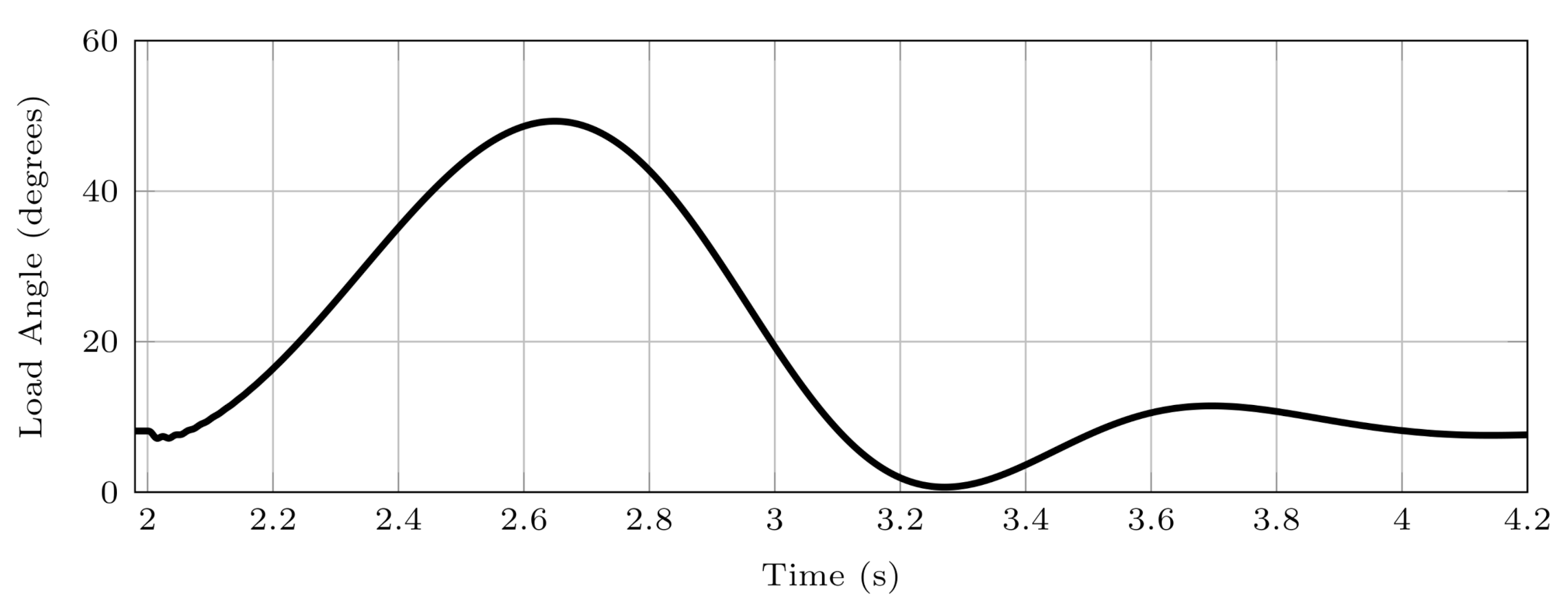
4.1. LVRT Dynamic Response
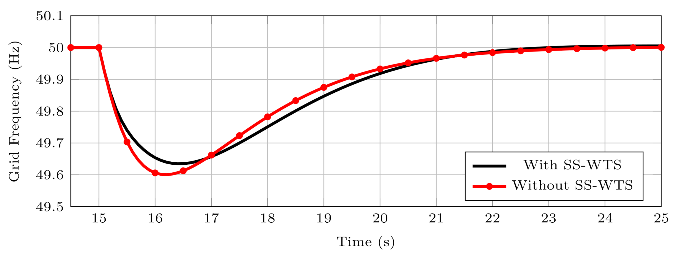
4.2. Inertial Response
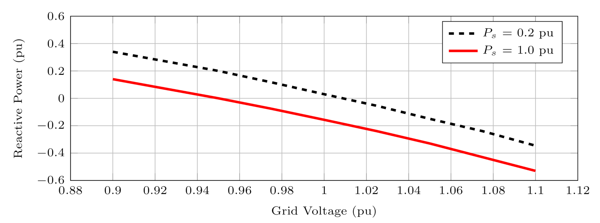
4.3. Reactive Power Response
5. Discussion
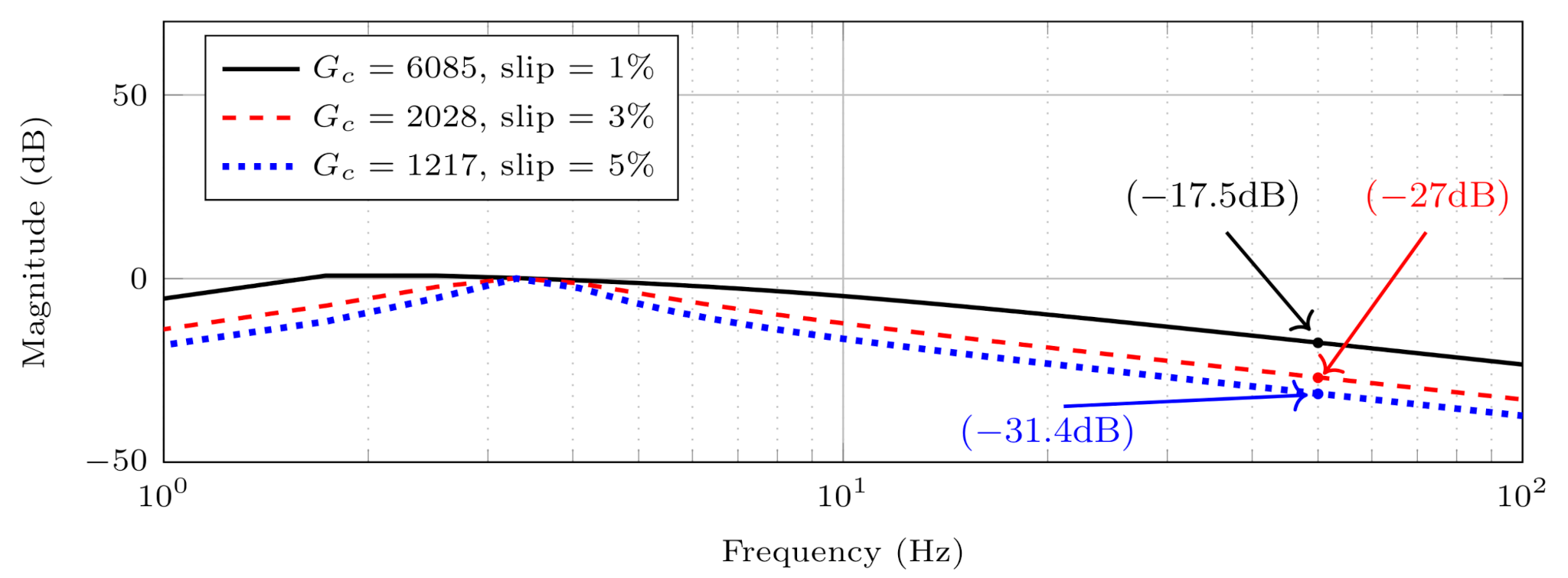
5.1. Slip versus Damping
5.2. Drivetrain Speed versus Damping
5.3. Reactive Power Compensation
6. Conclusions
Author Contributions
Conflicts of Interest
References
- IEA. Renewables 2020—Analysis. Available online: https://www.iea.org/reports/renewables-2020 (accessed on 15 February 2021).
- Global Wind Energy Council. Global Wind Report 2021. Available online: https://gwec.net/global-wind-report-2021/ (accessed on 24 March 2021).
- Gloe, A.; Jauch, C.; Räther, T. Grid Support with Wind Turbines: The Case of the 2019 Blackout in Flensburg. Energies 2021, 14, 1697. [Google Scholar] [CrossRef]
- Sourkounis, C.; Tourou, P. Grid Code Requirements for Wind Power Integration in Europe. Conf. Pap. Energy 2013, 2013, 437674. [Google Scholar] [CrossRef] [Green Version]
- Wu, Y.-K.; Chang, S.-M.; Mandal, P. Grid-Connected Wind Power Plants: A Survey on the Integration Requirements in Modern Grid Codes. In Proceedings of the 2019 IEEE/IAS 55th Industrial and Commercial Power Systems Technical Conference, Calgary, AB, Canada, 5–8 May 2019; IEEE: Calgary, AB, Canada, 2019; pp. 1–9. [Google Scholar]
- Denholm, P.L.; Sun, Y.; Mai, T.T. An Introduction to Grid Services: Concepts, Technical Requirements, and Provision from Wind; National Renewable Energy Laboratory: Golden, CO, USA, 2019. [Google Scholar]
- Luo, X.; Wang, J.; Wojcik, J.D.; Wang, J.; Li, D.; Draganescu, M.; Li, Y.; Miao, S. Review of Voltage and Frequency Grid Code Specifications for Electrical Energy Storage Applications. Energies 2018, 11, 1070. [Google Scholar] [CrossRef] [Green Version]
- Tu, S.; Zhang, B.; Jin, X. Research on DFIG-ES System to Enhance the Fast-Frequency Response Capability of Wind Farms. Energies 2019, 12, 3581. [Google Scholar] [CrossRef] [Green Version]
- Díaz-González, F.; Hau, M.; Sumper, A.; Gomis-Bellmunt, O. Participation of Wind Power Plants in System Frequency Control: Review of Grid Code Requirements and Control Methods. Renew. Sustain. Energy Rev. 2014, 34, 551–564. [Google Scholar] [CrossRef]
- Gevorgian, V.; Zhang, Y. Wind Generation Participation in Power System Frequency Response: Preprint. United States. Available online: https://www.osti.gov/servlets/purl/1339349 (accessed on 25 April 2021).
- Wu, Z.; Gao, W.; Gao, T.; Yan, W.; Zhang, H.; Yan, S.; Wang, X. State-of-the-art review on frequency response of wind power plants in power systems. J. Mod. Power Syst. Clean Energy 2018, 6, 1–16. [Google Scholar] [CrossRef] [Green Version]
- Dreidy, M.; Mokhlis, H.; Mekhilef, S. Inertia Response and Frequency Control Techniques for Renewable Energy Sources: A Review. Renew. Sustain. Energy Rev. 2017, 69, 144–155. [Google Scholar] [CrossRef]
- Aho, J.; Buckspan, A.; Laks, J.; Fleming, P.; Jeong, Y.; Dunne, F.; Churchfield, M.; Pao, L.; Johnson, K. A Tutorial of Wind Turbine Control for Supporting Grid Frequency through Active Power Control. In Proceedings of the 2012 American Control Conference (ACC), Montreal, QC, Canada, 27–29 June 2012; IEEE: Montreal, QC, Canada, 2012; pp. 3120–3131. [Google Scholar]
- De Rijcke, S.; Ergun, H.; Van Hertem, D.; Driesen, J. Grid Impact of Voltage Control and Reactive Power Support by Wind Turbines Equipped With Direct-Drive Synchronous Machines. IEEE Trans. Sustain. Energy 2012, 3, 890–898. [Google Scholar] [CrossRef]
- Tang, R.; Luo, B.; Deng, X.; Shen, Y. Research on Reactive Power and Voltage Control for Wind Farm Based on coordinate control of DFIGs and SVG. Procedia Comput. Sci. 2020, 175, 460–467. [Google Scholar] [CrossRef]
- Gonzalez-Longatt, F. Impact of Synthetic Inertia from Wind Power on the Protection/Control Schemes of Future Power Systems: Simulation Study. In Proceedings of the 11th IET International Conference on Developments in Power Systems Protection (DPSP 2012), Birmingham, UK, 23–26 April 2012. [Google Scholar]
- Muljadi, E.; Samaan, N.; Gevorgian, V.; Li, J.; Pasupulati, S. Short circuit current contribution for different wind turbine generator types. In Proceedings of the IEEE PES General Meeting, Minneapolis, MN, USA, 25–29 July 2010; pp. 1–8. [Google Scholar]
- Haddadi, A.; Farantatos, E.; Kocar, I.; Karaagac, U. Impact of Inverter Based Resources on System Protection. Energies 2021, 14, 1050. [Google Scholar] [CrossRef]
- Jia, J.; Yang, G.; Nielsen, A.H.; Muljadi, E.; Weinreich-Jensen, P.; Gevorgian, V. Synchronous Condenser Allocation for Improving System Short Circuit Ratio. In Proceedings of the 2018 5th International Conference on Electric Power and Energy Conversion Systems (EPECS), Kitakyushu, Japan, 23–25 April 2018; pp. 1–5. [Google Scholar]
- Potgieter, J.H.J.; Kamper, M.J. Design of New Concept Direct Grid-Connected Slip-Synchronous Permanent-Magnet Wind Generator. IEEE Trans. Ind. Appl. 2012, 48, 913–922. [Google Scholar] [CrossRef]
- Potgieter, J.H.J.; Kamper, M.J. Design Optimization of Directly Grid-Connected PM Machines for Wind Energy Applications. IEEE Trans. Ind. Appl. 2015, 51, 2949–2958. [Google Scholar] [CrossRef]
- Amuhaya, L.L.; Kamper, M.J. Design and optimisation of grid compliant variable-flux PM synchronous generator for wind turbine applications. In Proceedings of the 2015 IEEE Energy Conversion Congress and Exposition (ECCE), Montreal, QC, Canada, 20–24 September 2015; pp. 829–836. [Google Scholar] [CrossRef]
- Ockhuis, D.K.; Kamper, M.J.; Loubser, A.T. Hybrid Excitation Method for Higher Pole Number Grid-Tie Synchronous Generators. In Proceedings of the 2020 IEEE Energy Conversion Congress and Exposition (ECCE), Detroit, MI, USA, 11–15 October 2020; pp. 1439–1446. [Google Scholar] [CrossRef]
- Potgieter, J.H.J.; Kamper, M.J. Modeling and Stability Analysis of a Direct-Drive Direct-Grid Slip-Synchronous Permanent-Magnet Wind Generator. IEEE Trans. Ind. Appl. 2014, 50, 1738–1747. [Google Scholar] [CrossRef]
- van Wyk, P.J.J.; Kamper, M.J. Simplified Analysis of Nonoverlap Short-Circuited Coil Winding Slip Permanent Magnet Couplers. IEEE Trans. Ind. Appl. 2016, 52, 4740–4751. [Google Scholar] [CrossRef]
- Helsen, J.; Guo, Y.; Keller, J.; Guillaume, P. Experimental investigation of bearing slip in a wind turbine gearbox during a transient grid loss event. Wind Energy 2016, 19, 2255–2269. [Google Scholar] [CrossRef]
- Molinas, M.; Suul, J.A.; Undeland, T. Extending the life of gear box in wind generators by smoothing transient torque with statcom. IEEE Trans. Ind. Electron. 2010, 57, 476–484. [Google Scholar] [CrossRef]
- Licari, J.; Ugalde-Loo, C.E.; Ekanayake, J.B.; Jenkins, N. Damping of torsional vibrations in a variable-speed wind turbine. IEEE Trans. Energy Convers. 2013, 28, 172–180. [Google Scholar] [CrossRef]
- Reder, M.D.; Gonzalez, E.; Melero, J.J. Wind Turbine Failures—Tackling Current Problems in Failure Data Analysis. J. Phys. Conf. Ser. 2016, 753, 072027. [Google Scholar] [CrossRef]
- Saeedian, M.; Pournazarian, B.; Seyedalipour, S.S.; Eskandari, B.; Pouresmaeil, E. Emulating Rotational Inertia of Synchronous Machines by a New Control Technique in Grid-Interactive Converters. Sustainability 2020, 12, 5346. [Google Scholar] [CrossRef]
- Lipo, T. Analysis of Synchronous Machines; CRC Press: Boca Raton, FL, USA, 2017. [Google Scholar]
- Klontz, K.W.; Miller, T.J.E.; McGilp, M.I.; Karmaker, H.; Zhong, P. Short-Circuit Analysis of Permanent-Magnet Generators. IEEE Trans. Ind. Appl. 2011, 47, 1670–1680. [Google Scholar] [CrossRef]
- El-Metwally, M.; El-Shimy, M.; Mohamed, A.; Elshahed, M.; Sayed, A. Reliability assessment of wind turbine operating concepts using reliability block diagrams (RBDs). In Proceedings of the Nineteenth International Middle East Power Systems Conference (MEPCON), Cairo, Egypt, 19–21 December 2017; pp. 430–436. [Google Scholar] [CrossRef]
- Alhmoud, L.; Wang, B. A review of the state-of-the-art in wind energy reliability analysis. Renew. Sustain. Energy Rev. 2018, 81, 1643–1651. [Google Scholar] [CrossRef]
- Ockhuis, D.; Kamper, M.J.; Loubser, A.T. Impedance Matching of Direct Grid-Connected Renewable Energy Synchronous Generators. In Proceedings of the International SAUPEC/RobMech/PRASA Conference, Cape Town, South Africa, 29–31 January 2020; pp. 1–6. [Google Scholar]
- Polinder, H.; Van Der Pijl, F.F.A.; De Vilder, G.-J.; Tavner, P.J. Comparison of Direct-Drive and Geared Generator Concepts for Wind Turbines. IEEE Trans. Energy Convers. 2006, 21, 725–733. [Google Scholar] [CrossRef] [Green Version]
- Xue, Y.; Han, L.; Li, H.; Xie, L. Optimal design and comparison of different PM synchronous generator systems for wind turbines. In Proceedings of the 2008 International Conference on Electrical Machines and Systems, Wuhan, China, 17–20 October 2008; pp. 2448–2453. [Google Scholar]


| SS-WTS Parameter | Value | Grid Parameter | Value |
|---|---|---|---|
| Rated power () | 1.5 MW | Rated frequency | 50 Hz |
| Synchronous speed () | 1500 rpm | Line voltage (1.0 pu) | 690 V |
| Pole number (p) | 4 | Governor time constant () | 0.1 s |
| S-PMC gain () | 6085 | Steam flow time constant () | 0.2 s |
| Turbine inertia () | 6 kg | Re-heat time constant () | 7 s |
| Generator inertia () | 144 kg | Grid inertia constant (H) | 10 s |
| Gear ratio (GB) | 83 | Damping coefficient (D) | 1 |
| Synchronous reactance () | 0.5 pu | Proportional gain (P) | 10 |
| Stator resistance () | 0.035 pu | Integral gain (I) | 2 |
| Percentage rated slip () | 1 % | Regulating constant (R) | 0.05 |
| HS (1500 rpm) | MS (200 rpm) | MS (40 rpm) | |||||||
|---|---|---|---|---|---|---|---|---|---|
| Aspect ratio (X) | 1.14 | 0.31 | 0.23 | ||||||
| Volume () | 0.3 | 1.7 | 4.95 | ||||||
| S-PMC gain () | 6085 | 342,025 | 8,546,506 | ||||||
| Inertia (kg) | 144 | 5911 | 85,724 | ||||||
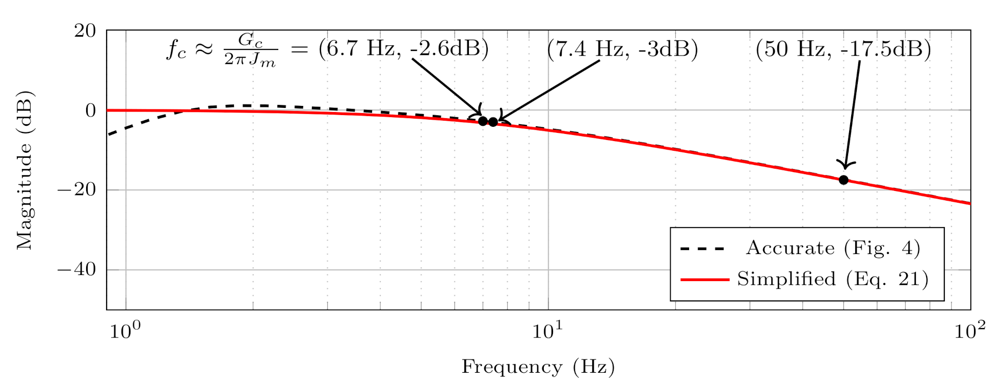
| Cut-off frequency, (Hz) | 6.7 | 9.2 | 15.9 | ||||||
| Attenuation, (dB) | −17.5 | −14.7 | −9.95 | ||||||
Publisher’s Note: MDPI stays neutral with regard to jurisdictional claims in published maps and institutional affiliations. |
© 2021 by the authors. Licensee MDPI, Basel, Switzerland. This article is an open access article distributed under the terms and conditions of the Creative Commons Attribution (CC BY) license (https://creativecommons.org/licenses/by/4.0/).
Share and Cite
Ockhuis, D.K.; Kamper, M. Potential of Slip Synchronous Wind Turbine Systems: Grid Support and Mechanical Load Mitigation. Energies 2021, 14, 4995. https://doi.org/10.3390/en14164995
Ockhuis DK, Kamper M. Potential of Slip Synchronous Wind Turbine Systems: Grid Support and Mechanical Load Mitigation. Energies. 2021; 14(16):4995. https://doi.org/10.3390/en14164995
Chicago/Turabian StyleOckhuis, Dillan Kyle, and Maarten Kamper. 2021. "Potential of Slip Synchronous Wind Turbine Systems: Grid Support and Mechanical Load Mitigation" Energies 14, no. 16: 4995. https://doi.org/10.3390/en14164995
APA StyleOckhuis, D. K., & Kamper, M. (2021). Potential of Slip Synchronous Wind Turbine Systems: Grid Support and Mechanical Load Mitigation. Energies, 14(16), 4995. https://doi.org/10.3390/en14164995