Abstract
The effect of the Au coated printed circuit board (PCB) as a current collector on the performance of fuel cells is demonstrated. In this study, optimized pulse electroplating was introduced, which was found to be much more effective compared to the direct current (DC) plating for the PCB fabrication based on the passive area from the potentiodynamic polarization scan. Variable electrochemical parameters such as applied potential and frequency for the pulse electroplating method are controlled. Using the polarization tests, the corrosion behavior of the Au coated PCB layer was also observed. From these basic data, the coating methods and electrochemical parameters were systematically controlled to achieve efficient results for direct methanol fuel cells (DMFCs). The stability test for the cell operation indicates that the micro DMFC with the Au coated PCB substrate formed at a frequency of 10 Hz exhibited the highest stability and performance. As a result, the Au coated PCB substrate using pulse electroplating at 1.5 V and 1 kHz can be a promising current collector for portable DMFCs.
1. Introduction
Fuel cells have attracted significant attention because it uses fuel (i.e., hydrogen) and an oxidizing agent (i.e., oxygen) to convert the chemical energy to electrical energy, thereby gaining remarkable attention as one of the potential energy devices [1,2]. Direct methanol fuel cells (DMFCs), which are a class of fuel cells, are of practical interest due to the convenience of their fuel to employ in portable applications [3]. However, they have not yet satisfied the requirements of entering the commercial market, which can be attributed to its a relatively low power density and stability compared with conventional portable power supply systems [4]. Despite the drawbacks of DMFCs, micro DMFCs are still attractive for portable applications because they can significantly reduce the size [5]. In particular, the current collector is one of the key factors to not only obtain a high efficiency, but also minimize the size of the DMFC [6]. Traditional current collectors such as graphite and stainless steel are not appropriate candidates for small DMFCs because of their restrictions in terms of flexibility.
However, printed circuit boards (PCBs) can be a promising candidate for a current collector in fuel cells, particularly micro DMFCs with a micro-electro-mechanical system (MEMS) [7,8]. PCBs are relatively feasible and cost-effective in which to fabricate a fuel cell because it can be formed into a smaller size with good flexibility [7,8]. Thus, many researchers have employed PCBs as current collectors to minimize the size of fuel cells [9,10]. Hereafter, the practical use of the PCB can be expanded for the convenience of the design and production cost [7,8]. However, the copper in PCB causes corrosion in acidic conditions, which is a required condition during the operation of the fuel cell [11]. The corrosion of the PCB substrate results in a significant decrease in performance and durability [11]. Therefore, it is important to prevent the corrosion of the PCB substrate in the commercialization of micro DMFCs.
To protect the PCB substrate from corrosion, metal deposition has been employed by chemical vapor deposition (CVD) or electroplating [12,13,14,15]. Of particular interest, electroplating with coating materials is economical, simple, and practicable for electrochemical processes [16]. The electroplating method is commonly used for decoration, anti-corrosion, and industrial plating according to the target materials [16]. Among the electroplating methods, the pulse current electroplating method (PCEM) is remarkably attractive, particularly compared to direct current (DC) plating [17,18]. This is because it can achieve a higher current density and introduce different parameters to enhance the electrochemical performance by forming a significantly uniform layer [19].
Herein, a new strategy for the micro DMFC with Au coated PCB substrates using a pulse electroplating method is reported. The Au coated PCB substrates were optimized by tuning many parameters such as potential, frequency, and deposition method. The Au coated PCB substrate fabricated by the pulse electroplating method was employed as a current collector for micro DMFC for a comparison with the conventional DC plated PCB substrate. Additionally, the cell performance, resistance, and 5000 min cell stability were measured for the micro DMFC with the Au coated PCB substrate formed by the pulse electroplating method to suggest an efficient fabrication condition in terms of electrochemical characteristics.
2. Materials and Methods
2.1. Preparation of PCB
Seventy μm PCB substrates were used and the microchannel was fabricated via lithography. A 5 μm nickel layer was deposited by electroless nickel plating after the conventional pretreatment process (Table 1).

Table 1.
Electroless nickel plating with the pretreatment processes.
After that, Au electroplating on nickel film was performed using a function generator (Agilent 33220A) with different pulse frequencies and duty cycles. The duty cycle is defined as the ratio of total on-time to total off-time. Aqueous solutions of Aurical, TKK-51-M20, KAu(CN)2KCN, and NH4OH were used under atmospheric conditions for direct current and pulse current plating. To investigate the corrosion resistance, Au coated PCBs by DC and pulse electroplating at 1 kHz (duty cycle 20%) was simply soaked in an acidic condition of 3 M methanol and a 1 M sulfuric acid mixed solution with a ratio of 1:1 and at 30 °C.
Figure 1 and Figure 2 show the schematic diagram of the electroplating instrument and the waveform of the pulse electroplating, respectively. The pulse frequency was varied from 0 (direct current), 10 Hz, 100 Hz, 1 kHz, 3 kHz, 5 kHz, and 10 kHz. The duty cycle of 20%, 50%, and 100% and a peak voltage of 1.0 V, 1.5 V, and 2.0 V were also changed to find the best condition.
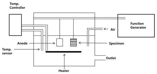
Figure 1.
Schematic diagram of the electroplating system.
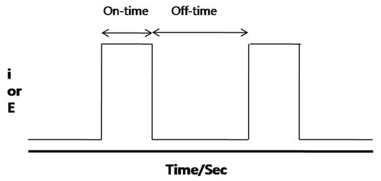
Figure 2.
A waveform of pulse electroplating.
2.2. Electrochemical Characterization
The polarization characteristics were tested using a potentiostat/galvanostat (Gamry reference 600) with a scan rate of 0.2 mV/s to demonstrate the corrosion rate of the surface. For the electrolyte, 1 M methanol and 0.1 M HCl were used. For the working electrode, a Au coated PCB substrate was used. For the counter electrode, platinum foil was used. For the reference electrode, the saturated calomel electrode was used. The parallel distance between the working electrode and counter electrode was 5 mm. The linear sweep voltammetry (LSV) was used to understand the potentiodynamic polarization by a scan rate of 0.2 mV/s with a potential range between 0 and 1.6 V at room temperature. The Au coated PCB samples were selected from the pulse plating conditions with a pulse frequency of 10 Hz, 100 Hz, and 1 kHz and of a peak voltage 1.0 V, 1.5 V, and 2.0 V, respectively, at fixed condition.
2.3. Operation and Performance Test of Micro DMFCs
A 2 M methanol solution was introduced to the anode at a rate of 2 mL/min using a rotary pump. The oxygen was injected into the cathode through the humidifier at a flow rate of 30 mL/min. An electric load (Hewlett Packard 6060B) was used to measure the current–voltage characteristics. The current was obtained by using the micro electric-load (Keithley 2000). The polarization curves were measured from the open circuit potential at a scan rate of 1 mV/s. The interfacial resistance was measured by using an electrochemical impedance analyzer (Gamry reference 600) with a frequency range between 100 Hz–100 kHz and with an AC amplitude of 10 mV. The average voltage value, which the signal introduced, was approximately 0.6 V. Of note, the anode was used as a reference electrode and the cathode was used as a working electrode. A 5000 min cell performance operation test experiment was also carried out until a performance degradation of 30% and for a maximum operating time of 5000 min.
3. Results
The effect of voltage on depositing Au metal on PCB substrates was demonstrated. The Au coated PCB substrates by the DC electroplating method were fabricated to compare the differences corresponding to the coating methods. The voltage was controlled from 1 V to 2 V without modifying other electrochemical parameters. In particular, the corrosion behavior was observed in the voltage range of 0–1.6 V, which is a typical operation potential range [20,21]. Of note, the calomel electrode was used as a reference electrode. Figure 3 shows the potentiodynamic polarization curves for Au coated PCB substrates with DC and pulse electroplating methods. Figure 3a presents the cells with Au coated PCB substrates formed at DC 1.0, 1.5, and 2 V. The current density of the cells with Au coated PCB substrates increased in terms of potential, indicating that the corrosion occurred. The passivation region currents at 1.0, 1.5, and 2.0 V were 1.27 × 10⁻³, 7.16 × 10⁻³, and 7.56 × 10⁻³, respectively. Of particular interest, the Au coated PCB substrate formed at DC 1.5 V showed the lowest corrosion current, meaning the highest corrosion resistance. The Au coated PCB substrates were formed using a pulse electroplating method with a variety of frequencies to demonstrate its effect on the corrosion. Figure 3b presents the potentiodynamic polarization curves for Au coated PCB substrates with the pulse electroplating method with various frequencies. The Au coated PCB substrate with the pulse electroplating method at 10 Hz exhibited an active corrosion behavior at 1.2 V, showing a much higher corrosion current compared to that at over 100 Hz. Meanwhile, the Au coated PCB substrates formed at frequencies at 100 Hz and 1 kHz showed passivation behavior in the potential range between 0.3 and 1.2 V. However, they were stable against corrosion. The passivation region currents at 10, 100, and 1000 Hz were 5.68 × 10⁻⁴, 8.89 × 10⁻⁴, and 6.38 × 10⁻⁵, respectively. Of particular interest, the Au coated PCB substrate formed by the pulse electroplating at 1 kHz exhibited a relatively low corrosion current in the potential range between 0.3 and 1.5 V, indicating a high corrosion resistance. Thus, the Au coated PCB substrate with the pulse electroplating method resulted in higher corrosion durability compared to that with the DC plating method. This is because the Au coated PCB substrate formed by the pulse electroplating method showed a significantly broad passivation behavior and small corrosion current relative to the DC plating method.
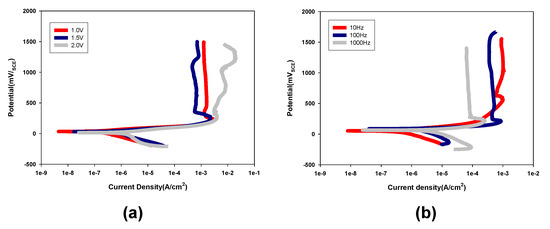
Figure 3.
Potentiodynamic polarization curves for Au coated PCB substrates formed by (a) a DC electroplating method with various applied potential and (b) a pulse electroplating method at various frequencies.
In general, the Au metal in the atmosphere has very high corrosion resistance due to the dense oxide film formed on the surface. Unlike the Au metal, the corrosion of electrodeposited Au penetrates into the crack existing in the electrodeposition layer and causes corrosion. Therefore, it is known that the crack-free or non-porous gold electrodeposition layer leads to the high resistance to corrosion. Figure 4 shows the corrosion rate measured by the weight loss method according to the frequency 10–1000 Hz and duty cycle 20%–80%. When the 20% duty cycle was applied, the corrosion rate of the Au coated PCB substrate showed the smallest value of 0.001 mg/cm2/min. Thus, we decided to use the 20% duty cycle for the electroplating experiment.
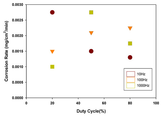
Figure 4.
Effect of duty cycle on the corrosion rate of Au coated PCB substrates.
Figure 5 presents top-view SEM images for Au coated PCBs, which were soaked in a 1 M methanol/3 M sulfuric acid mixed solution, to understand electrochemical resistance against corrosion in acidic conditions. Figure 5a,b shows the SEM images for DC electroplated PCBs before and after the soaking test, respectively. After soaking the PCB substrate in the 3 M methanol/1 M sulfuric acid mixture solution, abundant pinholes and defects on the PCB substrate appeared because of the corrosion. On the other hand, Figure 5c,d shows the SEM images for the Au coated PCB substrate formed by the pulse electroplating. The Au coated PCB substrate fabricated by the pulse electroplating exhibited a significantly smooth surface but showed relatively infrequent porous defects. This indicates that the Au coated PCB substrate based on pulse electroplating was considerably resistant to corrosion.
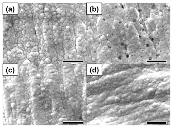
Figure 5.
SEM images for Au coated PCBs with different plating methods in the passage of time in acidic solution. A DC electroplating method after (a) 0 h, (b) 24 h and a pulse electroplating method after (c) 0 h, (d) 24 h. Scale bar is 5 μm.
The SEM analysis was conducted to demonstrate the effect of frequency on the surface morphology. Figure 6 presents the SEM images for Au coated PCB substrates as a function of the frequency with a peak voltage of 1.5 V. The partial defects appeared at a lower frequency, while the defects significantly appeared at a frequency over 3 kHz. This reflects that the high frequency for the pulse electroplating can lead to high agglomeration due to the non-uniform Au growth.
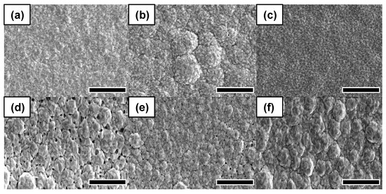
Figure 6.
SEM images for Au deposition at a variety of frequencies with a duty cycle of 20% and a peak voltage of 1.5 V. (a) 10 Hz, (b) 100 Hz, (c) 1 kHz, (d) 3 kHz, (e) 5 kHz, (f) 10 kHz. Scale bar is 5 μm.
Figure 7a shows the I–V curve for DMFCs with Au coated PCBs formed at a variety of frequencies in the pulse electroplating method. The Au coated PCB substrates fabricated at a frequency of 1 kHz exhibited the highest open-circuit voltage (OCV). This is because the Au coated PCB substrate formed by the pulse electroplating at a frequency of 1 kHz had a smooth surface without any noticeable defects (Figure 6). Additionally, the Au coated PCB substrate was highly resistant to corrosion while running the electrochemical reaction. However, in terms of power density, Figure 7b shows that the Au coated PCB substrates fabricated at a frequency of 10 Hz exhibited the highest power density at a current density of around 150 mA/cm2.
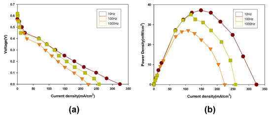
Figure 7.
(a) Voltage and (b) power density as a function of current density for DMFCs with Au coated PCB substrates using the pulse electroplating method formed at various frequencies.
To further investigate the corrosion of Au coated PCB substrates during the electrochemical cell test, electrochemical impedance measurement was carried out. Figure 8 presents the electrochemical impedance plot for DMFC cells with Au coated PCB substrates formed at 10 Hz and 1 kHz before and after the performance test. In addition, the impedance parameters are summarized in Table 2. Figure 8a shows that both cells with Au coated PCB substrates formed at 10 Hz and 1 kHz exhibited a low membrane resistance, which was approximately 0.74 Ω where the impedance plot intersects the x-axis [22]. Moreover, both cells with Au coated PCB substrates formed at 10 Hz and 1 kHz showed similar interfacial resistance regardless of the frequency of the pulse electroplating method. However, after the 5000 min cell performance test operation, the DMFC cells with Au coated PCB substrates formed at 10 Hz and 1 kHz exhibited higher membrane resistance and interfacial resistance compared to the initial cells, as can be seen in Figure 8b. In particular, the DMFC cells with Au coated PCB substrates showed different membrane resistance and interfacial resistance according to the applied frequency during the substrate fabrication. The DMFC cell with the Au coated PCB substrate fabricated at 1 kHz showed lower membrane resistance and interfacial resistance compared to that at 10 Hz. This is because the Au coated PCB substrate formed at 1 kHz had good surface morphological characteristics (i.e., uniformness, smoothness, defect-free, etc.), thereby providing a sufficient pathway for efficient electron transfer. As a result, the Au coated PCB substrate had good corrosion resistance, indicating a good candidate for the current collector based on the electroplating method [23].
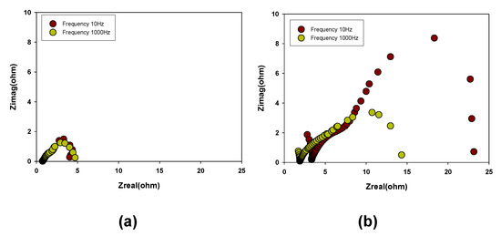
Figure 8.
Impedance plots for DMFCs with the Au coated PCB substrate using a pulse electroplating method at various frequencies: (a) initial, (b) after test.

Table 2.
Electrochemical parameters from the impedance plots.
The 5000 min cell performance operation test was performed with three micro DMFC cells with the Au coated PCB substrate at various frequencies. Figure 9 presents the current density with a constant voltage as a function of time. The DMFCs with Au coated PCB substrates formed at 10 and 100 Hz showed a significant cell degradation while running the 5000 min cell operation test over 1000 min. On the other hand, the micro DMFCs with the Au coated PCB substrate fabricated at 1 kHz exhibited the highest cell performance without severe degradation, even over 5000 min. Of note, the noticeable deviation of the current density at 2000–3000 min resulted from the water flooding during the 5000 min cell performance test [24]. Thus, the DMFCs with the Au coated PCB substrate formed at 1 kHz can be used to achieve 5000 min cell performance operation.
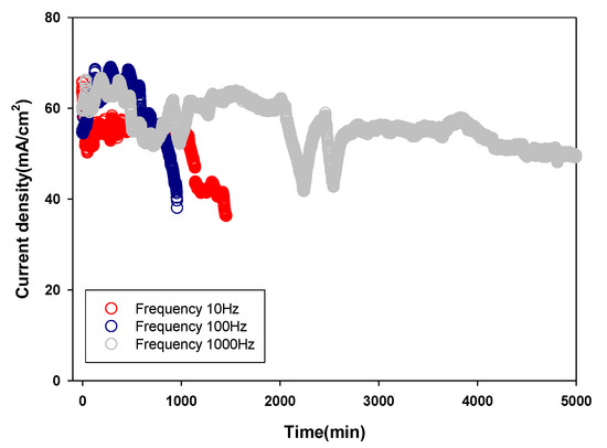
Figure 9.
The 5000 min cell performance operation test using DMFCs based on the Au coated PCB substrates using a pulse electroplating method with various frequencies.
4. Conclusions
A facile method to fabricate a Au coated layer on a PCB substrate via a pulse electroplating process as a current collector for DMFCs is reported. The electrochemical parameters including the electroplating method, applied potential, and frequency were systematically modified to achieve the optimized Au coated PCB substrates. Thus, the DMFC with Au coated PCB with the pulse electroplating method showed high electrochemical performance and corrosion durability. In conclusion, the DMFC with Au coated PCB, fabricated by pulse electroplating at 1 kHz and 1.5 V, exhibited the best cell performance due to the low membrane resistance and interfacial resistance.
Author Contributions
S.-S.P., conceptualization, methodology, validation, and investigation; N.-Y.S., conceptualization, methodology, validation, and investigation; Y.J., review and editing; C.L., review and editing; W.S.C., writing-original draft preparation and editing; Y.-G.S., supervision. All authors have read and agreed to the published version of the manuscript.
Funding
This research received no external funding.
Acknowledgments
This work was supported by the National Research Foundation of Korea (NRF) grant funded by the Korea government (MSIP) (NRF-2020R1F1A1075098), and this work was supported by the National Research Foundation of Korea (NRF) grant funded by the Korean government (MSIT) (No. 2020R1F1A1073201).
Conflicts of Interest
The authors declare no conflict of interest.
References
- Wang, Y.; Ruiz Diaz, D.F.; Chen, K.S.; Wang, Z.; Adroher, X.C. Materials, technological status, and fundamentals of PEM fuel cells—A review. Mater. Today 2020, 32, 178–203. [Google Scholar] [CrossRef]
- Staffell, I.; Scamman, D.; Velazquez Abad, A.; Balcombe, P.; Dodds, P.E.; Ekins, P.; Shah, N.; Ward, K.R. The role of hydrogen and fuel cells in the global energy system. Energy Environ. Sci. 2019, 12, 463–491. [Google Scholar] [CrossRef] [Green Version]
- Munjewar, S.S.; Thombre, S.B.; Mallick, R.K. Approaches to overcome the barrier issues of passive direct methanol fuel cell–Review. Renew. Sustain. Energy Rev. 2017, 67, 1087–1104. [Google Scholar] [CrossRef]
- Munjewar, S.S.; Thombre, S.B.; Mallick, R.K. A comprehensive review on recent material development of passive direct methanol fuel cell. Ionics 2017, 23, 1–18. [Google Scholar] [CrossRef]
- Junoh, H.; Jaafar, J.; Nik Abdul, N.A.H.; Ismail, A.F.; Othman, M.H.D.; Rahman, M.A.; Aziz, F.; Yusof, N. Performance of polymer electrolyte membrane for direct methanol fuel cell application: Perspective on morphological structure. Membranes 2020, 10, 34. [Google Scholar] [CrossRef] [Green Version]
- Fang, S.; Zhang, Y.; Zou, Y.; Sang, S.; Liu, X. Structural design and analysis of a passive DMFC supplied with concentrated methanol solution. Energy 2017, 128, 50–61. [Google Scholar] [CrossRef]
- Raj, V. 16-Direct methanol fuel cells in portable applications: Materials, designs, operating parameters, and practical steps toward commercialization. In Direct Methanol Fuel Cell Technology; Dutta, K., Ed.; Elsevier: Amsterdam, The Netherlands, 2020; pp. 495–525. ISBN 978-0-12-819158-3. [Google Scholar]
- Braz, B.A.; Moreira, C.S.; Oliveira, V.B.; Pinto, A.M.F.R. Effect of the current collector design on the performance of a passive direct methanol fuel cell. Electrochim. Acta 2019, 300, 306–315. [Google Scholar] [CrossRef]
- Wang, L.; He, M.; Hu, Y.; Zhang, Y.; Liu, X.; Wang, G. A “4-cell” modular passive DMFC (direct methanol fuel cell) stack forportable applications. Energy 2015, 82, 229–235. [Google Scholar] [CrossRef]
- Barbera, O.; Stassi, A.; Sebastian, D.; Bonde, J.L.; Giacoppo, G.; D’Urso, C.; Baglio, V.; Aricò, A.S. Simple and functional direct methanol fuel cell stack designs for application in portable and auxiliary power units. Int. J. Hydrogen Energy 2016, 41, 12320–12329. [Google Scholar] [CrossRef]
- Hong, P.; Liao, S.; Zeng, J.; Huang, X. Design, fabrication and performance evaluation of a miniature air breathing direct formic acid fuel cell based on printed circuit board technology. J. Power Sources 2010, 195, 7332–7337. [Google Scholar] [CrossRef]
- Sundarrajan, S.; Allakhverdiev, S.I.; Ramakrishna, S. Progress and perspectives in micro direct methanol fuel cell. Int. J. Hydrogen Energy 2012, 37, 8765–8786. [Google Scholar] [CrossRef]
- Lee, Y.H.; Noh, S.T.; Lee, J.H.; Chun, S.H.; Cha, S.W.; Chang, I. Durable graphene-coated bipolar plates for polymer electrolyte fuel cells. Int. J. Hydrogen Energy 2017, 42, 27350–27353. [Google Scholar] [CrossRef]
- Yuan, Z.; Zhang, Y.; Leng, J.; Zhao, Y.; Liu, X. Performance of air-breathing direct methanol fuel cell with Au-coated aluminum current collectors. Int. J. Hydrogen Energy 2012, 37, 2571–2578. [Google Scholar] [CrossRef]
- Sabaté, N.; Esquivel, J.P.; Santander, J.; Hauer, J.G.; Verjulio, R.W.; Gràcia, I.; Salleras, M.; Calaza, C.; Figueras, E.; Cané, C.; et al. New approach for batch microfabrication of silicon-based micro fuel cells. Microsyst. Technol. 2014, 20, 341–348. [Google Scholar] [CrossRef]
- Giurlani, W.; Zangari, G.; Gambinossi, F.; Passaponti, M.; Salvietti, E.; Di Benedetto, F.; Caporali, S.; Innocenti, M. Electroplating for decorative applications: Recent trends in research and development. Coatings 2018, 8, 260. [Google Scholar] [CrossRef] [Green Version]
- Ye, F.; Wang, Z.; Xu, C.; Yuan, M.; Liu, P.; Yang, W.; Liu, G. Mechanism and kinetic study of pulse electrodeposition process of Pt/C catalysts for fuel cells. Renew. Energy 2020, 145, 514–520. [Google Scholar] [CrossRef]
- Chandrasekar, M.S.; Pushpavanam, M. Pulse and pulse reverse plating-Conceptual, advantages and applications. Electrochim. Acta 2008, 53, 3313–3322. [Google Scholar] [CrossRef]
- Arunsunai Kumar, K.; Paruthimal Kalaignan, G.; Muralidharan, V.S. Direct and pulse current electrodeposition of Ni-W-TiO2 nanocomposite coatings. Ceram. Int. 2013, 39, 2827–2834. [Google Scholar] [CrossRef]
- Dilasari, B.; Jung, Y.; Kwon, K. Comparative study of corrosion behavior of metals in protic and aprotic ionic liquids. Electrochem. Commun. 2016, 73, 20–23. [Google Scholar] [CrossRef]
- Luo, H.; Li, Z.; Mingers, A.M.; Raabe, D. Corrosion behavior of an equiatomic CoCrFeMnNi high-entropy alloy compared with 304 stainless steel in sulfuric acid solution. Corros. Sci. 2018, 134, 131–139. [Google Scholar] [CrossRef]
- Długołecki, P.; Ogonowski, P.; Metz, S.J.; Saakes, M.; Nijmeijer, K.; Wessling, M. On the resistances of membrane, diffusion boundary layer and double layer in ion exchange membrane transport. J. Memb. Sci. 2010, 349, 369–379. [Google Scholar] [CrossRef]
- Yasuda, H.; Yu, Q.S.; Chen, M. Interfacial factors in corrosion protection: An EIS study of model systems. Prog. Org. Coat. 2001, 41, 273–279. [Google Scholar] [CrossRef]
- Chen, M.; Wang, M.; Yang, Z.; Ding, X.; Wang, X. Long-term degradation behaviors research on a direct methanol fuel cell with more than 3000h lifetime. Electrochim. Acta 2018, 282, 702–710. [Google Scholar] [CrossRef]
Publisher’s Note: MDPI stays neutral with regard to jurisdictional claims in published maps and institutional affiliations. |
© 2021 by the authors. Licensee MDPI, Basel, Switzerland. This article is an open access article distributed under the terms and conditions of the Creative Commons Attribution (CC BY) license (https://creativecommons.org/licenses/by/4.0/).