Article

Airflow Analysis of the Haida Plank House, a Breathing Envelope

by
Roberto Alonso González Lezcano
1 and
María Jesús Montero Burgos
2,*
1
Escuela Politécnica Superior, Montepríncipe Campus de Boadilla del Monte, Universidad San Pablo-CEU, CEU Universities, 28040 Madrid, Spain
2
Facultad de Humanidades y Ciencias de la Comunicación, Campus de Moncloa, Universidad San Pablo-CEU, CEU Universities, 28040 Madrid, Spain
*
Author to whom correspondence should be addressed.
Energies 2021, 14(16), 4871; https://doi.org/10.3390/en14164871
Submission received: 28 May 2021 / Revised: 28 July 2021 / Accepted: 3 August 2021 / Published: 10 August 2021
(This article belongs to the Special Issue Energy Efficiency and Indoor Environment Quality)

Abstract

:
The Haida plank house is one of the most important models built by the native American Indians. Built on the southwest coast of Canada, it adapts the tradition of the ancient pit houses to the requirements of the humid and cold climate characteristic of the Haida Gwaii Islands. This construction is composed by two main pieces: the central pit covered by a wooden envelope. Both protect its dwellers and their hearths. The ventilation system is based on two solutions: the gaps between the wall planks and a smoke hole that can be opened or closed in the roof at will. The aim of the present research is to analyze the way these two elements arrange the indoor airflow in order to ensure the comfortability of the house. Four cases have been proposed, according to four different dimensions for the gaps: 1, 2, 3 and 4 cm. Each case has been doubled in order to determine how the state of the smoke hole affected the corresponding results. This way, it has been concluded that if the gaps’ width becomes higher than 4 cm, the airflow velocity comfort level would be exceeded. It is been possible to observe how the state of the smoke hole influences the way the air moves around the dwelling.

1. Introduction

The dwellings built by the Native American Indians are one of the most interesting examples of primitive architecture that can be found. When analyzing them, it can be seen that they were designed in the search for one main goal: to achieve a construction that takes advantage of its environment and of the available resources in the most efficient way [1]. In order to succeed, it was necessary to have a deep knowledge about the way that the environment worked and the advantages and disadvantages offered by those resources. Such was the case of these communities.
When the European explorers arrived in North America by the end of the 15th century, they found a bunch of cultures that represented a period of history that was already lost in their own continent [2,3,4]. Among the members of those expeditions, there were not only sailors but also artists, historians, engineers, botanists, or anthropologists, whose work is extremely valuable nowadays [5]. Specifically in the architecture field, they gathered a great amount of information about the dwellings they had the opportunity to visit. Dimensions, building materials, building processes, or indoor distribution are some of the features described in the documentation they created.
The present research is focused on one of these dwellings, the plank house built by the communities settled in the coast of southwest of Canada and northwest of the United States. The goal of this work is to analyze the passive ventilation strategies that are contained in its design.
The study case was built by the Haida, one of the most important groups of the zone. Two types of houses were built by this community, according to two different structural solutions. The use of six or four beams was the main decision to make (Figure 1).
The first one is probably the eldest [1] (p. 271). The house that has been chosen for the present research, dwelling number 3 from the village of Ninstints, corresponds to this structural solution.
The Haida name for the village was “Red Cod Island Town”, which clearly indicates the way of life of its inhabitants. Its first European visitors changed its name from the one of the chief of the tribe, Nañ stîns, “He who is two”. It contained twenty dwellings, although at present, just seventeen of them can be located, as can be seen in Figure 2 [6] (p. 103).
As usually happens in this type of villages, the line of dwellings was arranged along the coast line in order to ease the entry to the ocean and to take advantage of the airflow that arose between the mountains and the ocean. This mechanism was a very useful feature of these locations, since this airflow kept the wooden structures of the dwellings from being rotten. The red cedar wood (Thuja plicata Donn ex D. Don) was chosen by the Haida, since it is naturally covered by a special oil that also protects it from moisture [7] (p. 63).
Walls were composed by a line of wooden planks (Figure 3). It was necessary to leave a little gap between them, so the airflow could enter into the house. As told by Underhill [8] (p. 84), one of these dwellings was rebuilt some time ago by modern Indians. When it was finished, they lit a hearth indoors, and smoke filled the house completely. They could not understand how their ancestors could have lived in such a smoky place. An Indian elder man who had seen all the process explained them how important those gaps between the planks were: “Why, it was the cracks. With enough cracks, you have fine circulation of air”.
The door consisted of a hole carved in a totem pole, and it usually was covered with another plank, hung from a cedar bark rope, and blocked with some poles fit in the structure [10] (p. 21).
This way, the structure of the dwelling was solved by means of wooden beams and poles, and its envelope was composed of wooden planks. Roofs were built in two different ways: wooden planks or bark sheets. The first option was used by the richest families, while the second possibility was chosen by the rest of the community [10] (p. 21). Whatever solution was chosen, these pieces were overlapped, such as the tiles used in modern roofs, in order to keep rainwater away from the house; finally, they were weighted down with stones [11] (p. 72).
The indoor space was arranged around a central terraced pit [12] (p. 146B). It was the place where the hearth was lit. There could be several hearths, if there was more than one family living in the house. The roof planks could be removed in order to let the smoke out.
As explained before, the target of the present research work is to analyze the airflow system that triggers indoor ventilation. There are three elements to focus on: the dimensions of the gaps between the planks, the influence of the smoke hole in the indoor airflow, and the way the airflow behaves in the pit.

2. Materials and Methods

2.1. Materials

The dwelling analyzed was built by the Haida in the village of Ninstints, Haida Gwaii Islands, British Columbia. Specifically, it is dwelling number three. It was built according to the oldest type of structure, as explained before, and it had a central pit, which was the usual piece of this type of dwelling [10] (p. 107). Its floor plan was 14.1 per 14.85 m. The pit (9.45 per 9.9 m) was 1.8 m deep; it was delimited by two steps that were each 75 cm high. The height of the house has been obtained by taking the Haida dwelling drawn by Niblack in 1890 (Figure 4); [13] (p. 42) as reference. This way, its height has been estimated as 3.5 m for the side walls and as 5.03 m for the ridge of the two main façades.

2.2. Methods

First of all, the ventilation rate of the dwelling has been calculated in order to determine if it was high enough. This way, the 2nd Florida Solar Energy Center method has been used [14] (pp. 101–103). This method is used to dimension the inlet and outlet areas in cross-ventilated spaces. It is based on the pressure increase between the inlet and the outlet openings. The results must be read taking into account that they are not influenced by the ambient temperature and that this method assumes that every inlet opening has the same positive pressure value, and every outlet has the same negative pressure value.
According to this method, the ventilation rate is calculated according to the following formula:
Ach = [A·W·√(f3·f4·PD)]/[4.3 × 10−4·V].
“A” is equal to the total effective area of the openings (m2) and is determined following the next expression:
A = (Ao·Ai)/(Ao2 + Ai2)0.5.
The outlet area is represented by “Ao” (m2), and the inlet area is represented by “Ai“ (m2). “W” is equal to the wind velocity (m/s). There are two correction factors represented by letter “f”, f3 and f4. On the one hand, “f3” introduces the effect of the nearby constructions and is equal to “g/h”, being “h” the height of the nearby obstacles and “g” the distance between them. On the other hand, “f4” is determined by the floor number where the case study in question is located. “PD” is the subtraction between the windward pressure coefficient (WPC) and the leeward pressure coefficient (LPC) [14] (p. 102).
The dwelling has been modeled in Autodesk Revit 2020®. This model has been exported as a SAT file in order to carry out the corresponding calculations in Autodesk CFD 2021® [15]. These calculations have been developed taking into account the average conditions of the zone where these dwellings were built. This way, in order to obtain representative results, ten locations have been taken, and their wind velocity average has been determined (Figure 5). Just summer wind velocity has been taken into account, since that is the season when ventilation is more important.
As can be seen in Figure 6, the model has been placed in a box. Air material has been assigned to this element, as it has to the gaps between the planks, the smoke hole, and the air mass located inside the house. Wood material has been assigned to the planks, floor, and roof.
As boundary conditions, wind force (8.24 m/s) (Figure 5) has been assigned to one of the sides of the box, normal to the longitudinal axe of the house. Zero pressure has been assigned to the opposite face. This way, the latter absorbed the windflow emitted by the former. The top and longitudinal sides of the box have been characterized as “slim/slippery”. The free sides of the gaps have also been assigned zero pressure and the smoke hole has as well (Figure 6).
The dimensions of the air box were established by the software Autodesk CFD®. Its width is five times the width of the dwelling, its length is five times the length of the dwelling, and its height is five times the height of the dwelling.
The solution mode was established as “steady state”. The resolution of the mesh was defined as 1, the edge growth rate was defined as 1.1, two points were the minimum on the edges, and 10 was the number of points for the longest edge. These meshes were designed automatically by the CFD software. Calculations have been carried out accepting the Autodesk CFD® criteria, since it limits automatically the optimum amount of iterations to achieve convergence. This way, “Intelligent solution control” and “Automatic convergence assessment” have been selected and set as “tight”. The calculation system has been developed from the algorithm SIMPLER, which belongs to one of the best-known CFD tools family. The turbulence was simulated by means of the model k-epsilon, which has been widely developed and studied. The validity of the results that have been obtained are backed by the use of Autodesk CFD®, which is a software that has been tested since 2013. Its calculations have been compared in numerous research studies, such as the one developed in the Victoria University of Wellington by Dr. Jing Li [17]. Autodesk® provides an ample compilation of verification studies; some of them compare test models against experimental results, and others compare them against empirical hand calculations [18].
Four alternatives have been calculated according to the gaps dimensions: 1, 2, 3, and 4 cm wide. Each case is calculated twice, since the smoke hole can be either open or closed. Five locations have been chosen inside each model, as shown in Figure 7. Each location has been divided into several levels, from level 0 to level 450, in such a way that one point was placed each 50 cm (Figure 7).

3. Results

3.1. Ventilation Rate
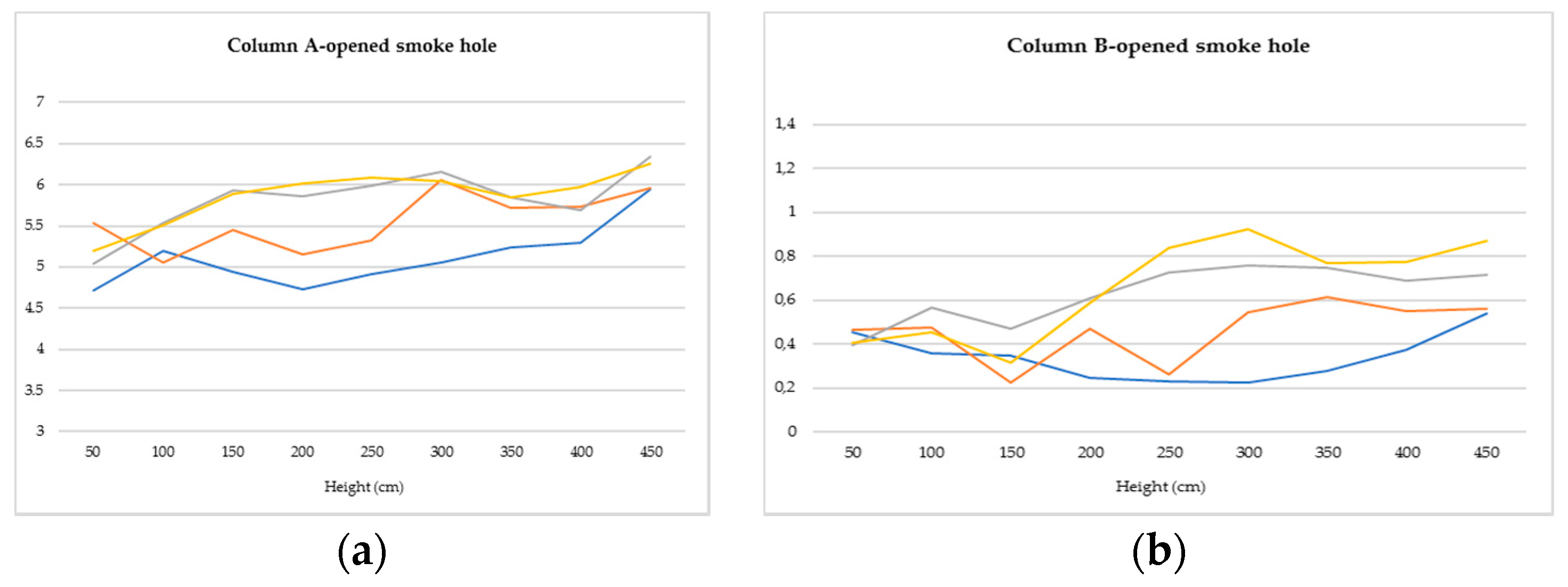
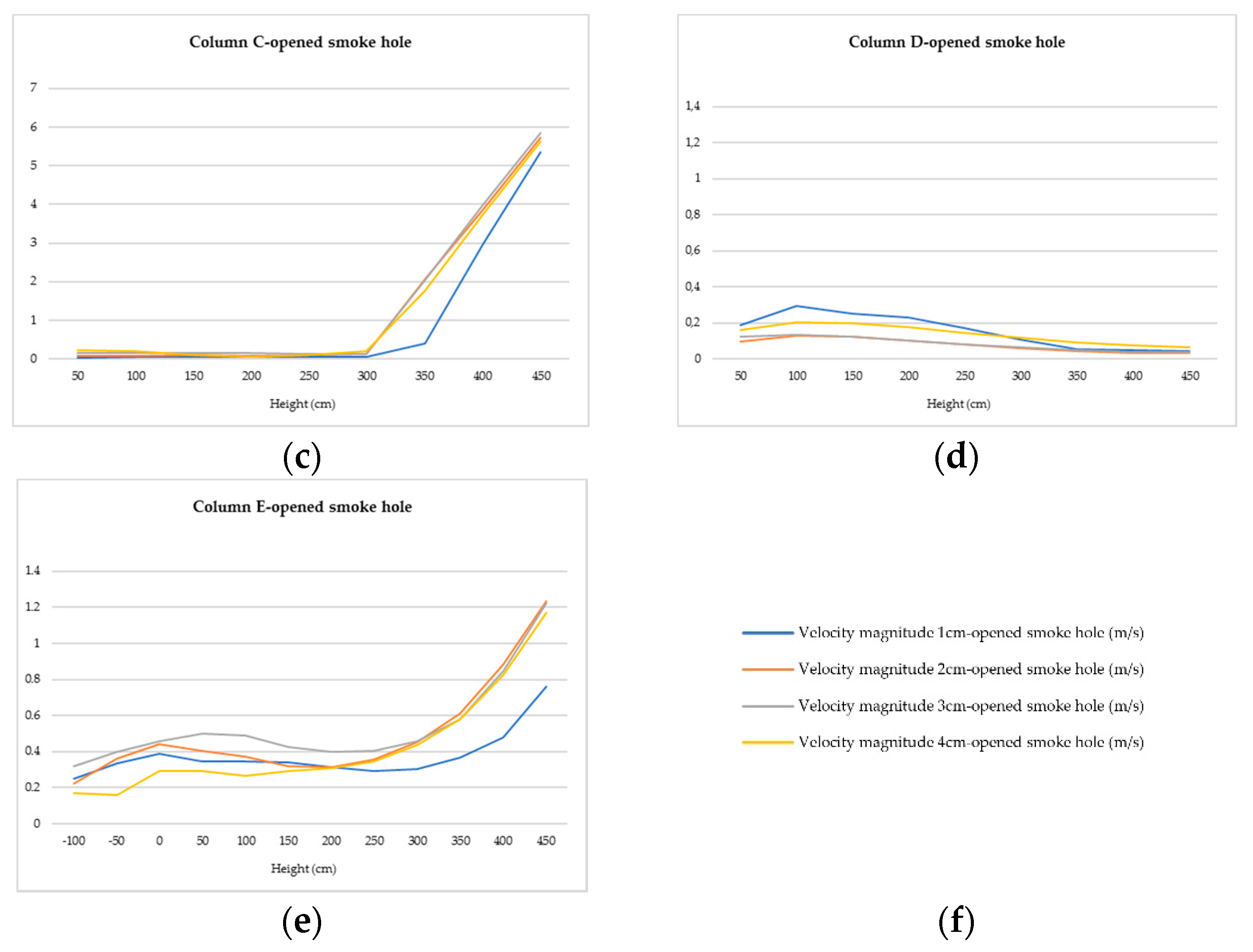
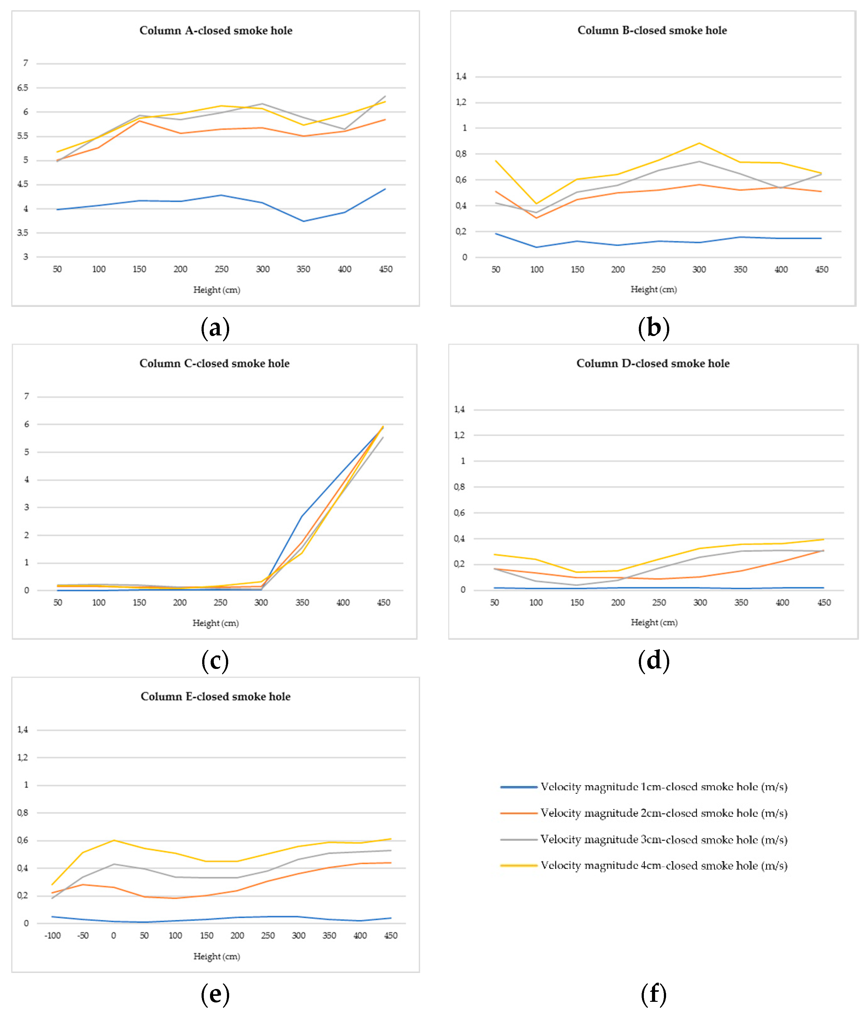
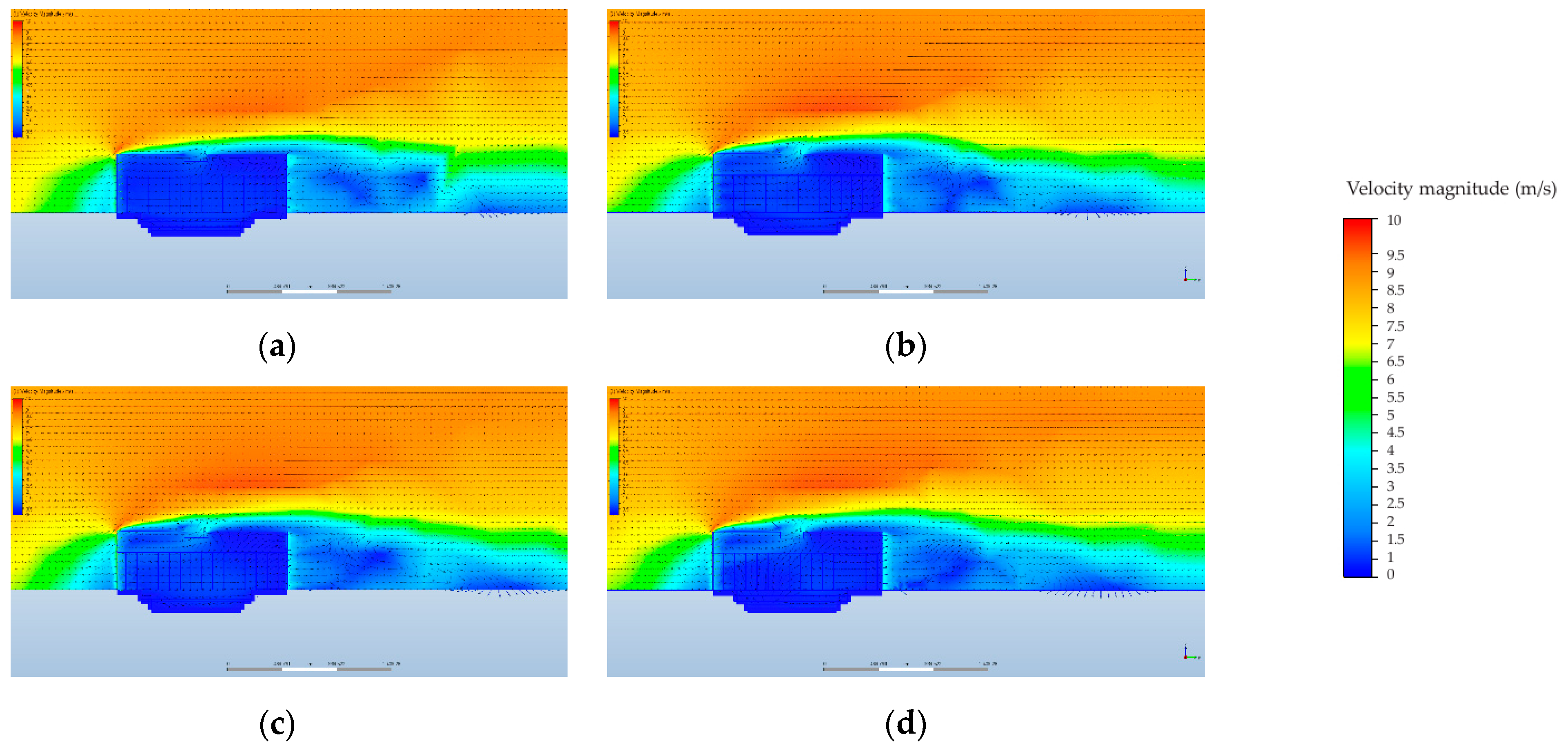
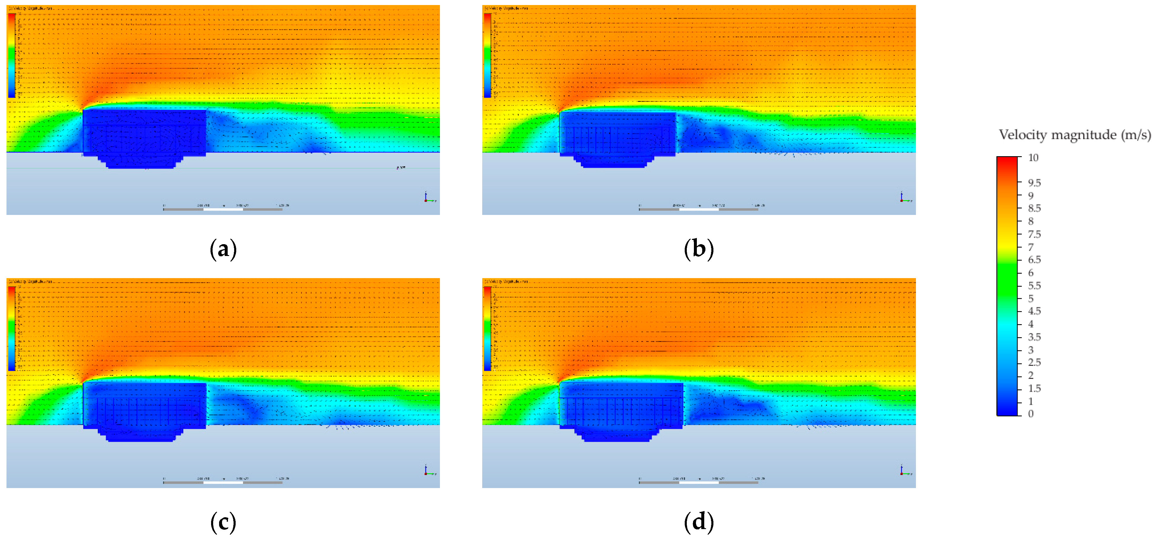
As explained before, the ventilation rate of this dwelling has been calculated according to the Second Florida Solar Energy Center method in order to determine if the openings were wide enough to accomplish this minimum requirement. The Spanish Building Technical Code establishes that this value has to be higher or equal to 0.63 ach in abodes.
Calculations have been carried out and, as can be seen, the plank house whose gaps are 1 cm wide accomplished this requirement (Table 1).
Once it was determined that the ventilation rate was high enough if the gaps between wall planks were equal to or higher than 1 cm wide, the research could be focused on analyzing the way the airflow moved inside the dwelling, varying the dimension of these gaps.

3.2. Airflow

3.2.1. Airflow above the Central Pit

The velocity magnitude has been calculated in five columns, each one composed by nine points from 50 to 450 cm high. Each column has been calculated for two cases, since the smoke hole could be either opened or closed.
As can be seen in Figure 8 and Figure 9, the velocity magnitude increases as the gaps’ width does. The thinner the gaps are, the more regular the velocity is along the corresponding column.
“A” is the column that gathers the higher velocity values (Figure 7). The highest values are not obtained by the thinnest gaps, in such a way that wind passes through the gaps that are 1 cm wide more slowly than through the 4 cm gaps. This difference is higher if compared with the closed-smoke hole model. Even though the velocity through the 1 cm gap is lower when the smoke hole is closed, it can be seen that it is almost invariable for the rest of the widths.
The greatest oscillations occur in columns “B” and “D”, which are both located near the envelope. The velocity varies along them in an irregular way from the floor to the top of the house. However, their lowest values are reached close to the work plane (about 70 cm high), and the highest ones are found near the ceiling.
The most irregular case is the one of column “C”. Its levels are similar to “B” at 50 cm below the floor, and they reach velocities as high as the “A” column when approaching the ceiling. So, the airflow behavior at this point is a combination of both “A” in the highest part of the dwelling and “B” in the lowest one. Whether the smoke hole is opened or closed, the result is the same.
Column “D” is near the outlet gaps. Column “C” is close as well, but the velocity is higher inside the gaps located besides “D”. The difference between the results obtained for “C” and “D” is based on the proximity of the former to the smoke hole: that is, the element that triggers the velocity increase in “C” at 300 cm high. Actually, the velocity magnitude is almost null near the ceiling in column “D”, which means that the smoke of the hearths could be trapped in this zone. The same velocity level takes place in column “C” below 300 cm high.
The column that is clearly influenced by the state of smoke hole is “E”. As can be seen, the airflow is much more regular if this element is closed rather than if it is opened. The most remarkable fact is that the pit stays almost the same. The airflow velocity does not vary in this zone whatever the state of the smoke hole. These graphs also reflect that as expected, the velocity near the smoke hole is higher when it is opened.
In the following diagrams, the way the wind flows along the longitudinal axis of the house, the same as the wind vector, can be observed (Figure 10 and Figure 11). They show how the opened smoke hole creates a quiet zone in the leeward elevation. This zone becomes smaller when the smoke hole is closed, and it turns softer and bigger as long as the gap between the planks becomes bigger. This fact reflects the way Haida transformed these dwellings along the year by moving these boards in order to let the air in. This way, there was no limit between indoors and outdoors, as happened in tipis.
The airflow velocity inside the dwelling is lower when the smoke hole is closed, but it is higher on the part of the roof surface touched by the airflow from indoors. This way, the roof erosion was more intense when the smoke hole was closed.

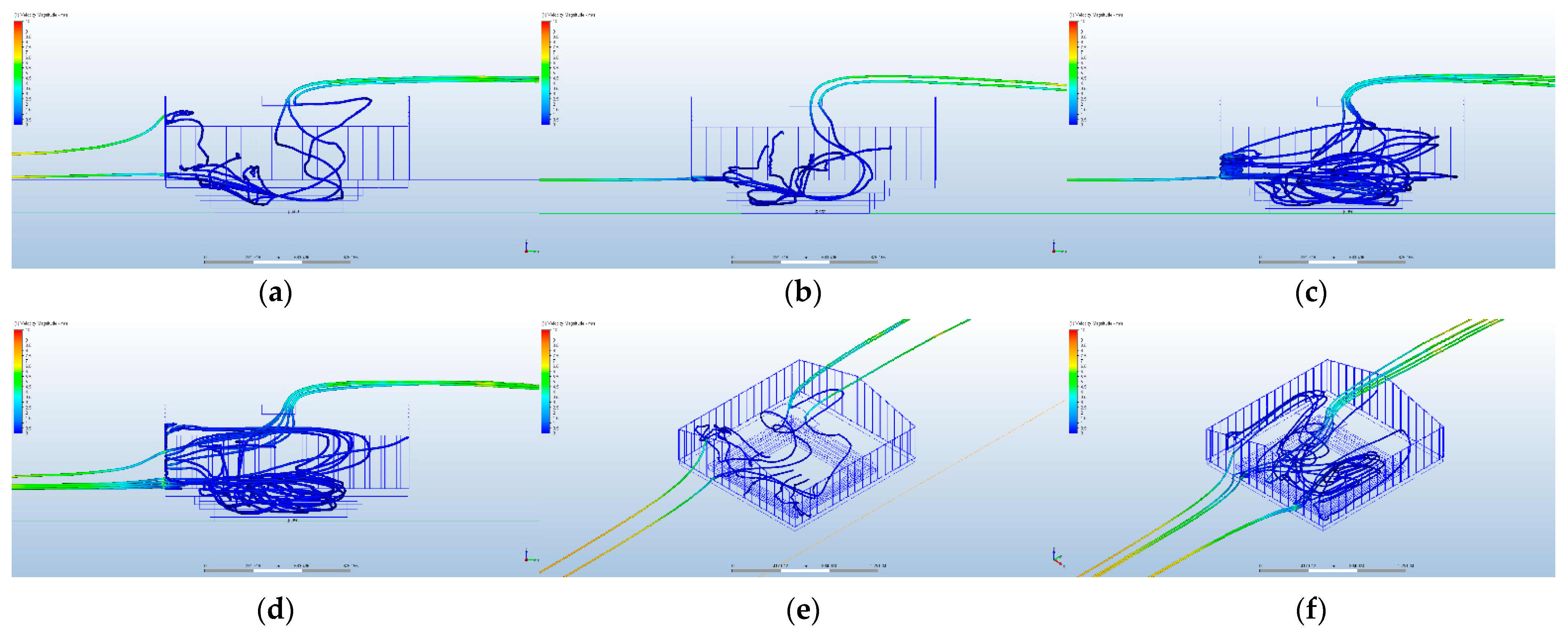
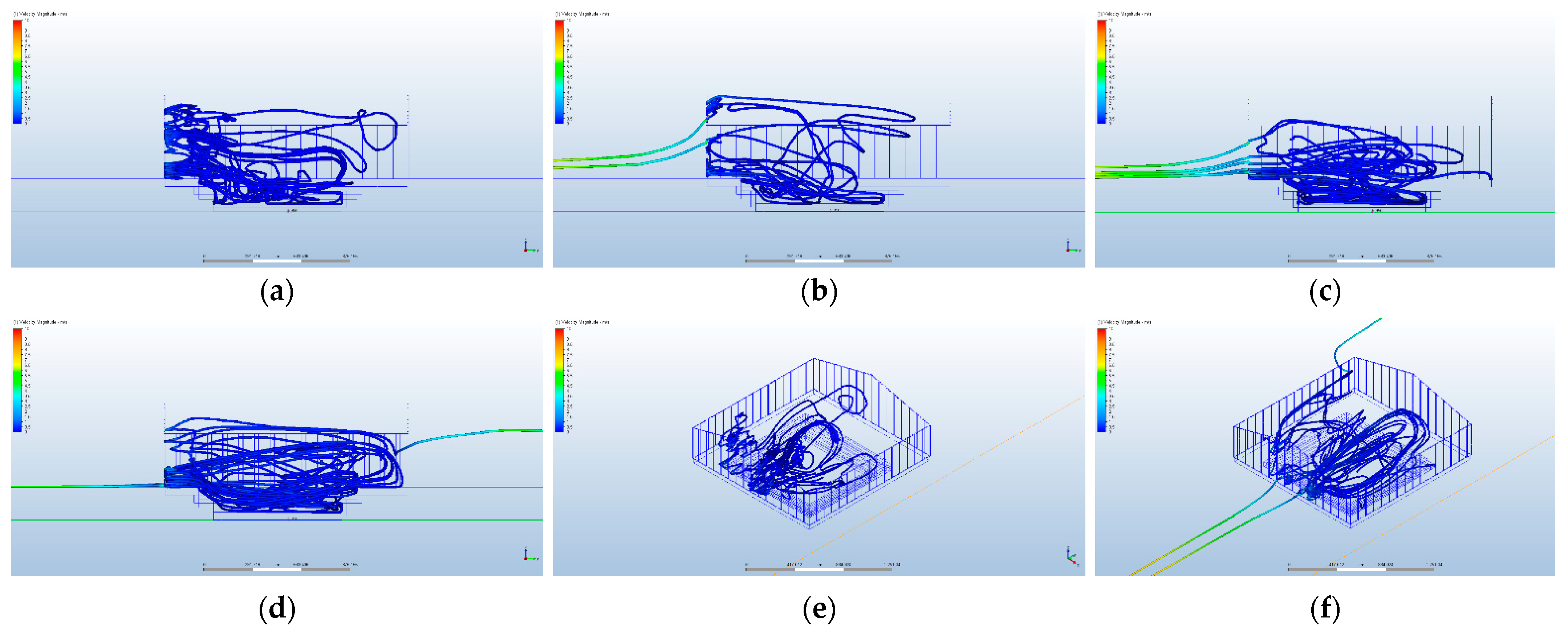
3.2.2. Airflow in the Central Pit

By means of the following diagrams (Figure 12 and Figure 13), it has been possible to observe how the airflow behaves inside the central pit, where the hearths were lit. As they show, the wider the gaps are between the planks, the bigger the turbulence is inside the pit. They are even more complex if the smoke hole is closed.
As explained before, the airflow velocity was very low in this zone. This turbulence helped to keep the its air clean, but at the same time, the smoke would spread over the place more easily.
When the smoke hole is closed, the airflow in the pit stays in it and cannot exit the house directly. The only case where it becomes possible is the one of the 4 cm gaps (Figure 12f). If the gaps are thinner, the air in the pit has to be dragged by other flows that are able to exit.
Instead, when the smoke hole is opened, the air in the pit usually exits by itself.
In addition to the turbulence, it is important to take into account the velocity of the air particles. Figure 8 and Figure 9 show that the airflow is almost static in the pit if the gaps are 1 cm wide.

4. Discussion

According to the results, it can be asserted that the plank house was a pit covered by a breathable envelope. The pit was the main area of the house, where the hearths were lit and where daily life took place. The origin of this space is lost in time, but it can be found in several Indian dwellings. In different ways, it is the main piece of the Navajo hogans [1] (pp. 325–336), of the pit-houses built by the Thompsons groups [1] (pp. 176–179) and, even, of the sod-houses built by the Yup’ik communities [19] (pp. 119–156). The thermal stability was the target to accomplish in most of these cases, but as shown in previous studies [20], there are some examples in which this function is not so clear. The plank houses are one of them. The depth of the pit is not enough to influence the indoor temperature of the house, so it has to have another aim. As can be seen in the previous graphs, it is a peaceful zone inside the house, where the hearths could be lit up and where the cold air from outdoors decelerated.
The idea of versatility is as important in the plank house as it was in the tipi, which is the most important nomad dwelling. The planks of Haida houses could be removed or displaced as the hide envelope of the tipis could be opened or closed. This way, both models search for the continuity between indoors and outdoors, as nomad tribes do in their daily life [21]. However, the most important point is that these communities analyze conscientiously their environment and take advantage of the opportunities it offers to them [22]. As Atta [23] asserts, an affordable and sustainable housing design requires integrating economic and environmental solutions from a social point of view. Traditional architecture offers a unique opportunity to investigate how these three factors can coexist successfully.
As the research developed by Knowles and Easton established [1,24], Native American architecture is much more complex than expected at first sight. Their research was focused on Acoma dwellings, which are adobe pueblos from New Mexico. Knowles determined that the orientation of Acoma dwellings let the houses take advantage of the solar radiation as much as possible; meanwhile, Easton analyzed the ascending currents of air that occur along the main elevation of the Pueblo houses.
As another example, the tipis could be taken. Their conical design was based on the shape of a Cottonwood tree leaf [25] (p. 7). This specie of tree is well known for being able to resist strong winds, as the tipis do. Its leaves move, adapting to the wind direction in order to survive. This is the way the ventilation system works in the tipis, taking advantage of the main wind in such a way that it takes out the hearth smoke from indoors.
The present research is rooted in the field of virtual archaeology, which is a discipline that offers an enriching amount of opportunities for other areas. The virtual reconstruction of disappeared buildings can show forgotten solutions that are particularly useful nowadays. In this case, the reconstruction of the Haida plank house has been possible thanks to the archaeological records about Ninstints as well as due to the journals written by the first European and Russian explorers. Research studies such as those developed by Trebeleva and Glazov [26] are undoubtedly essential to understand how the ancient buildings were designed and the technical solutions they contained.
The plank house that has been analyzed is the one built by the Haida community in the Haida Gwaii Islands. However, the “plank house” model can be found all along the Pacific coast of North America in different ways. From California, where the Hoopa built their own models, to the coastal Salish in the Vancouver Island and Puget Sound, who dwelled their shed houses, there are enough models to carry out a deeper comparison study.

5. Conclusions

By analyzing the results shown previously, it can be concluded that if the gaps between the planks of the Haida dwelling are wider than 4 cm, the summer airflow comfort limits (1.1 m/s) would be exceeded inside the building [27] (p. 305). However, it should be taken into account that the present research has assigned the same width to every gap in each case, which is a variable that could be studied in further research.
This way, it can be seen that the envelope of the Haida plank house let the indoor area breath. This dwelling is composed of two elements: this envelope and a central pit. The Native American dwellings were usually designed around a central hearth that is protected by an envelope [1]. This envelope can establish a solid limit between indoor and outdoor, as, for instance, happens in the New Mexican adobe pueblos, but there is another group of dwellings that uses this envelope to let the indoor area breath. Among them, the Wichita grass houses can be found. As occurs in the Haida plank houses, their grass envelope is designed to let the smoke out; that is to say, the whole envelope breathes. This type of solution can also be found in the thatched British cottages, confirming the idea that this type of solution is common in high humidity locations. What turns the Haida plank house into a special case is the combination of this breathing envelope and a central pit. As can be seen in Figure 10 and Figure 11, if the smoke hole is closed, this zone is protected from the air currents that take the smoke out and keep the cedar planks dry. Thereby, the smoke hole works as a ventilation trigger and can be used to renovate the air of the dwelling at will.
By means of modern technology, this type of envelope is being developed at the moment by many architecture research centers and offices. For instance, the design developed by the engineer Tobias Becker from Stuttgart can be cited [28]. His envelope is composed of multiple cells controlled by changes in air pressure. This way, they regulate the incident light and the airflow as skin pores and pigments regulate a living being. In addition, the idea behind the Al Bahar towers should be highlighted [29]. Built in Abu Dhabi by Abdulmajid Karanouh and Aedas, their envelopes are integrated by multiple cells inspired in the Arabic lattice. These cells are closed or opened according to the meteorology, since they can let the air and the solar radiation in or they can shield the buildings from them. The prototype developed in Los Angeles by professor Doris Kim Sung also offers an interesting option [30]. Called Bloom, this experiment proposes the use of metal sheets that curl when heated in such a way that the whole structure casts shadows and lets ventilation under specific areas when temperature rises. Obviously, all these projects are technically much more complex than the plank house built by the Haida several centuries ago, but the concept hidden behind all of them was the same. The point was not just to design a breathing envelope but to get the best of every element that composes a building by means of a deep knowledge of the possibilities offered by the environment in order to save the available resources.

Author Contributions

Conceptualization, R.A.G.L. and M.J.M.B.; methodology, R.A.G.L. and M.J.M.B.; software, R.A.G.L. and M.J.M.B.; investigation, M.J.M.B.; resources, R.A.G.L.; writing—original draft preparation, review and editing, R.A.G.L. and M.J.M.B.; supervision, R.A.G.L.; project administration, R.A.G.L.; funding acquisition, R.A.G.L. All authors have read and agreed to the published version of the manuscript.

Funding

The authors wish to thank CEU San Pablo University Foundation for the funds dedicated to the Project Ref. USP CEU-CP20V12 provided by CEU San Pablo University.

Institutional Review Board Statement

Not applicable.

Informed Consent Statement

Not applicable.

Conflicts of Interest

The authors declare no conflict of interest.

References

  1. Nabokov, P.; Easton, R. Native American Architecture; Oxford University Press: New York, NY, USA, 1989. [Google Scholar]
  2. Spencer, R.; Jennings, J. The Native Americans: Ethnology and Backgrounds of the North American Indians; Harper & Row: New York, NY, USA, 1977. [Google Scholar]
  3. Gunther, E. Indian Life on the Northwest Coast of North America (as Seen by the Early Explorers and Fur Traders during the Last Decades of the Eighteenth Century); The University of Chicago Press: Chicago, IL, USA, 1972. [Google Scholar]
  4. Pritzker, B. A Native American Encyclopedia: History, Culture and Peoples; Oxford University Press: New York, NY, USA, 2000. [Google Scholar]
  5. Bakeless, J. America as Seen by Its First Explorers: The Eyes of the Discovery; Dover Publications: New York, NY, USA, 1989. [Google Scholar]
  6. MacDonald, G. Ninstints, Haida World Heirtage Site; University of British Columbia Press in Association with the University of British Columbia Museum of Anthropology: Vancouver, BC, Canada, 1987. [Google Scholar]
  7. Sobel, E.; Gahr, D.; Ames, K. Household Archaeology on the Northwest Coast; Berghahn Books: Ann Abour, MI, USA, 2006. [Google Scholar]
  8. Underhill, R. Indians of the Pacific Northwest; United States Department of the Interior, Bureau of Indian Affairs, Branch of Education: Washington, DC, USA, 1944.
  9. Jarzombek, M. Architecture of First Societies; John Wiley & Sons: Hoboken, NJ, USA, 2013. [Google Scholar]
  10. MacDonald, G. Haida Monumental Art: Villages of the Queen Charlotte Islands; University of British Columbia Press: Vancouver, BC, Canada, 1995. [Google Scholar]
  11. Stewart, H. Cedar: Tree of Life to the Northwest Coast Indians; Douglas & McIntyre: Madeira Park, BC, Canada, 1995. [Google Scholar]
  12. Dawson, G.; Geological Survey of Canada. Report of Progress for 1878-79. Report on the Queen Charlotte Islands-1878; Dawson Bros.: Montreal, QC, Canada, 1880. [Google Scholar]
  13. Niblack, A. The coast Indians of southern Alaska and northern British Columbia; based on the collections in the U.S. National Museum, and on the personal observation of the writer in connection with the survey of Alaska in the seasons of 1885, 1886, and 1887. In U.S. National Museum Annual Report 1888; Johnson Reprint Corporation: New York, NY, USA, 1890; pp. 225–386. Available online: https://archive.org/details/coastindiansofso00nibl/page/n5/mode/2up (accessed on 5 August 2021).
  14. Yarke, E. Ventilación Natural de Edificios; Nobuko: Buenos Aires, Argentina, 2005. [Google Scholar]
  15. Autodesk Help-Natural Ventilation. Available online: https://knowledge.autodesk.com/support/cfd/learn-explore/caas/CloudHelp/cloudhelp/2014/ENU/SimCFD/files/GUID-F6011744-B69B-47D0-BB2B-50E1BA8DC32D-htm.html (accessed on 24 May 2021).
  16. Windfinder. Available online: https://es.windfinder.com/#3/49.5042/9.5421 (accessed on 24 May 2021).
  17. Li, J.; Delmas, A.; Donn, M.; Willis, R. Validation and Comparison of Different CFD Simulation Software Predictions of Urban Wind Environment Based on AIJ Wind Tunnel Benchmarks. In Proceedings of the Symposium on Simulation for Architecture and Urban Design, Delft, The Netherlands, 4–7 June 2018; Available online: https://dl.acm.org/citation.cfm?id=3289777 (accessed on 5 August 2021). [CrossRef]
  18. Autodesk Simulation CFD 2021-Verification. Available online: https://help.autodesk.com/view/SCDSE/2021/ENU/?guid=GUID-3DD39B64-5638-4D0D-9175-1FBC95E629FC (accessed on 23 July 2021).
  19. Lee, M.; Reinhardt, G. Eskimo Architecture: Dwelling and Structure in the Early Historic Period; University of Alaska Press: Fairbanks, AL, USA, 2003. [Google Scholar]
  20. Montero Burgos, M.J.; Sanchiz Álvarez de Toledo, H.; González Lezcano, R.A.; Galán de Mera, A. The Sedentary Process and the Evolution of Energy Consumption in Eight Native American Dwellings: Analyzing Sustainability in Traditional Architecture. Sustainability 2020, 12, 1810. [Google Scholar] [CrossRef] [Green Version]
  21. Couchaux, D. Habitats Nomades; Alternatives: Paris, France, 2011. [Google Scholar]
  22. Rapoport, A. House form and Culture; Prentice-Hall: Englewood Cliffs, NJ, USA, 1969. [Google Scholar]
  23. Atta, N.; Dalla Valle, A.; Campioli, A.; Chiaroni, D.; Talamo, C. Construction Technologies for Sustainable Affordable Housing within Fragile Contexts: Proposal of a Decision Support Tool. Sustainability 2021, 13, 5928. [Google Scholar] [CrossRef]
  24. Knowles, R. Energy and Form; The MIT Press: Cambridge, MA, USA, 1980. [Google Scholar]
  25. Goble, P. Tipi: Home of the Nomadic Buffalo Hunters; World Wisdom: Bloomington, IL, USA, 2007. [Google Scholar]
  26. Trebeleva, G.; Glazov, K.; Kizilov, A.; Sakania, S.; Yurkov, V.; Yurkov, G. Roman Fortress Pitiunt: 3D-Reconstruction of the Monument Based on the Materials of Archaeological Research and Geological Paleoreconstructions. Appl. Sci. 2021, 11, 4814. [Google Scholar] [CrossRef]
  27. Neila, F. Arquitectura Bioclimática en un Entorno Sostenible; Munilla-Lería: Madrid, España, 2004. [Google Scholar]
  28. Tébe. Available online: https://www.tebe.berlin/innovation/ (accessed on 25 July 2021).
  29. Karanouh, A.; Kerber, E. Innovations in dynamic architecture. J. Façade Des. Eng. 2015, 3, 185–221. [Google Scholar] [CrossRef] [Green Version]
  30. DO|SU Studio Architecture. Available online: https://www.dosu-arch.com/bloom (accessed on 25 July 2021).
Figure 1. (a) Four beams model based on [1] (p. 270); (b) Six beams model based on [1] (p. 270).
Energies 14 04871 g001
Figure 2. Plan of Ninstints (dwelling number 3 in red) based on [6] (p. 10).
Energies 14 04871 g002
Figure 3. Exploded axonometric of a Haida dwelling construction system based on [9] (p. 171).
Energies 14 04871 g003
Figure 4. Cutaway section of Haida dwelling based on [13] (detail of plate XXXV).
Energies 14 04871 g004
Figure 5. Average summer wind velocity values (m/s). Ten locations where the Haida built plank houses have been taken. The value that has been used (8.24 m/s) corresponds to the average of all of them based on [16].
Energies 14 04871 g005
Figure 6. Screenshot in which boundary conditions are indicated (Autodesk CFD®).
Energies 14 04871 g006
Figure 7. (a) Axonometry, screenshot showing the location of the five points analyzed (Autodesk CFD®); (b) Floorplan of the same model (Autodesk CFD®); (c) Section of the same model (Autodesk CFD®).
Energies 14 04871 g007
Figure 8. Values of velocity for the five columns of points, which is analyzed when the smoke hole of the plank house is opened (m/s) (Microsoft Excel®; Autodesk CFD®).
Energies 14 04871 g008aEnergies 14 04871 g008b
Figure 9. Values of velocity for the five columns of points, which is analyzed when the smoke hole of the plank house is closed (m/s) (Microsoft Excel®; Autodesk CFD®).
Energies 14 04871 g009
Figure 10. Airflow velocity and direction inside and nearby the plank house, whose smoke hole is opened (a) 1 cm gap; (b) 2 cm gap; (c) 3 cm gap; (d) 4 cm gap (Autodesk CFD®).
Energies 14 04871 g010
Figure 11. Airflow velocity and direction inside and nearby the plank house, whose smoke hole is closed (a) 1 cm gap; (b) 2 cm gap; (c) 3 cm gap; (d) 4 cm gap (Autodesk CFD®).
Energies 14 04871 g011
Figure 12. Airflow traces in the pit when the smoke hole is opened. (a) 1 cm gap; (b) 2 cm gap; (c) 3 cm gap; (d) 4 cm gap; (e) Axonometry corresponding to (a); (f) Axonometry corresponding to (d) (Autodesk CFD®).
Energies 14 04871 g012
Figure 13. Airflow traces in the pit when the smoke hole is closed. (a) 1 cm gap; (b) 2 cm gap; (c) 3 cm gap; (d) 4 cm gap; (e) Axonometry corresponding to (a); (f) Axonometry corresponding to (d) (Autodesk CFD®).
Energies 14 04871 g013
Table 1. Ventilation rate for 1 cm wide gaps.
Outlet Area A0Inlet Area AiTotal Area AWPCLCPPDVolume VWind Velocity Wf3f4Ach
10.49 m20.62 m20.62 m20.7−0.10.8813.81 m38.24 m/s0.4118.3
Publisher’s Note: MDPI stays neutral with regard to jurisdictional claims in published maps and institutional affiliations.

