1. Introduction
Due to their simple structure, high power density, excellent control performance, and low loss, permanent magnet synchronous motors (PMSMs) are widely used in many applications, such as servo control systems, electric vehicles, electric aircraft, and robotic actuators [
1]. However, due to safety concerns, space limitations, or cost requirements, the bus voltage of the PMSM drive system is limited. Thus, the bus voltage utilization is important in such drive systems [
2,
3,
4].
Some researchers employ the open-winding topology to drive the motors for the higher bus voltage utilization [
4,
5,
6,
7,
8,
9,
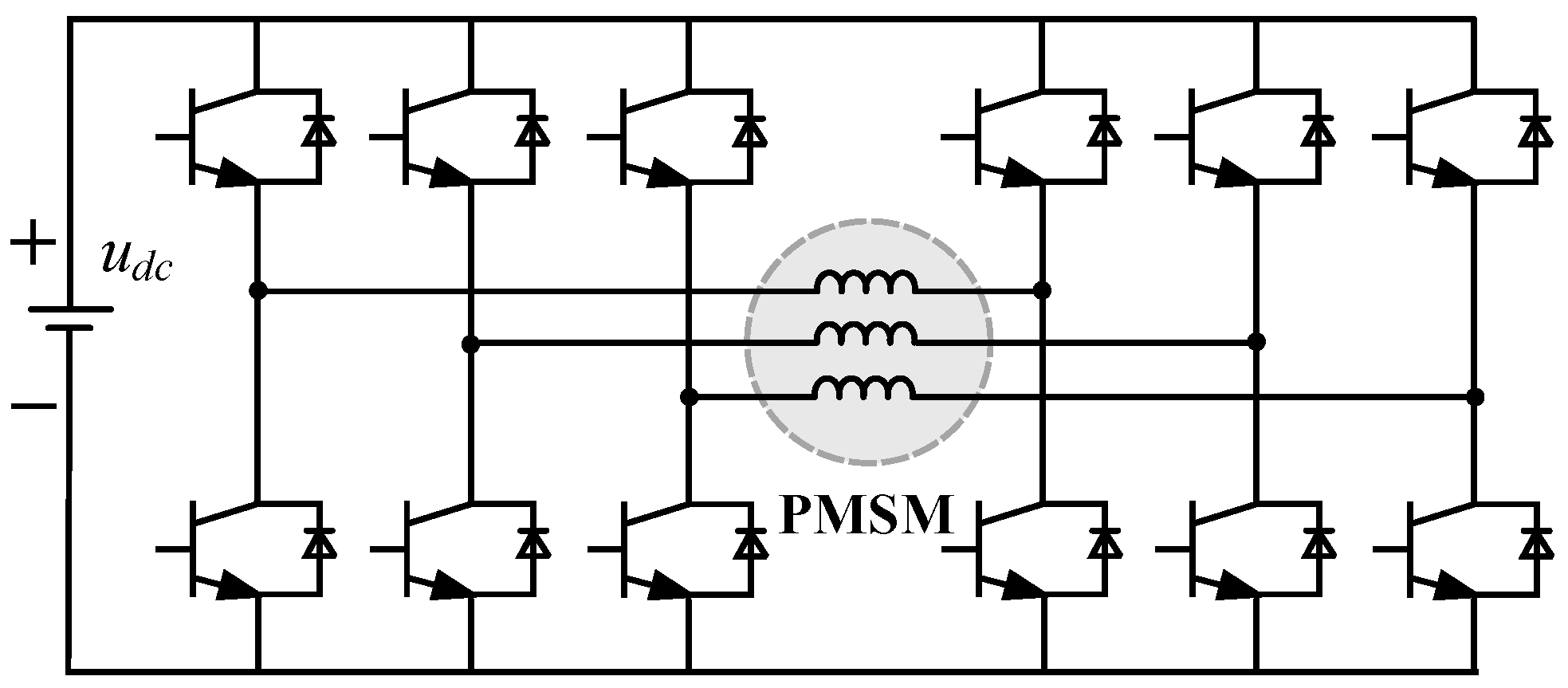
10]. By simply opening the neutral point of the phase windings, then connecting the three ends to another inverter, the motor is subsequently supplied by two inverters simultaneously, as shown in
Figure 1. Therefore, the supplied voltage level for the motor is doubled [
5]. However, such open-winding-topology-driven PMSM systems are costly due to the double switching devices, which means it needs six half-bridge power modules (HBPMs). Moreover, the control strategy of the three-phase open-winding-topology-driven PMSM system is complex, since there are 64 different switching states, while the conventional star-winding topology only has eight different switching states [
8]. Things are more complicated in the five-phase counterpart, because there are 10 HBPMs in the drive system [
4,
10].
From the perspective of system cost and control implementation, series-winding topology can be regarded as the evolution of open-winding topology [
11]. It not only has the characteristic of high DC-link voltage utilization, but also reduces the number of switching devices compared to open-winding topology [
12]. An
N-phase series-winding-topology-driven PMSM system only requires
N + 1 HBPMs, while the counterpart of open-winding topology requires 2
N HBPMs [
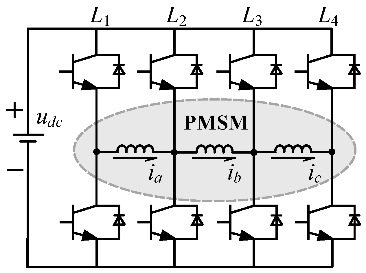
13]. A three-phase series-winding PMSM drive system is revealed in
Figure 2. In this way, the total system cost is reduced. At the same time, the control strategy is easier to implement due to fewer switching states.
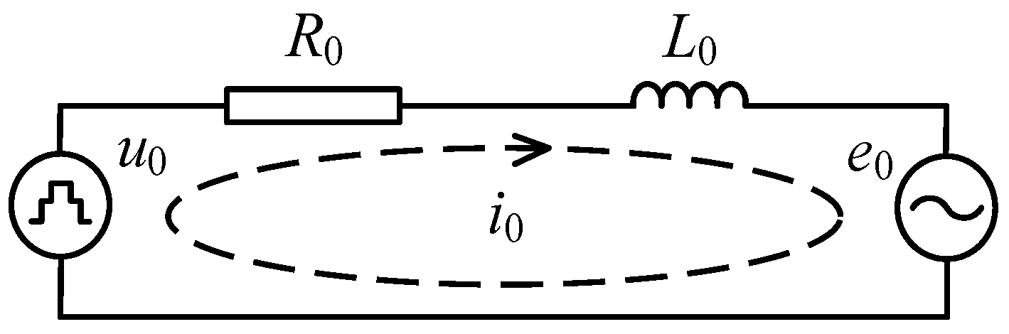
However, series-winding topology also contains a zero-sequence loop, as presented in
Figure 3, while the zero-sequence voltage will result in a corresponding zero-sequence current through it. Such zero-sequence current leads to additional harmonic components and torque ripple [
14]. Not only will the specific voltage vectors generate the zero-sequence current, but the rotor harmonic back-electromotive force and the nonlinearity of the inverter will contribute to it too [
15,
16]. Among the three factors, what we can adjust is the voltage vector by changing the switching state. Therefore, we can choose to use voltage vectors containing zero-sequence components to suppress the zero-sequence current [
12].
To pursue satisfactory current control performance, a bulk of current control strategies have been proposed, such as hysteresis current control, field-orient control, and predictive current control [
1]. Hysteresis current control has a simple structure and fast dynamic response, but it also brings large torque ripples [
17]. In contrast, field-orient control has lower torque ripples. However, it is time-consuming to tune the controller parameters. Recently, due to the quality dynamic performance, predictive current control is widely used in PMSM drives [
18]. There are two sorts of predictive current control, namely, finite control set-model predictive current control and deadbeat predictive current control (DBPCC). For the sake of steady-state performance, DBPCC is more preferred due to flexible voltage vector combinations [
7]. Thus, we could promote the DBPCC to the series-winding-topology-driven PMSM system, but the zero-sequence loop should be well handled.
Besides, phase current plays an irreplaceable role in the control of the motor [
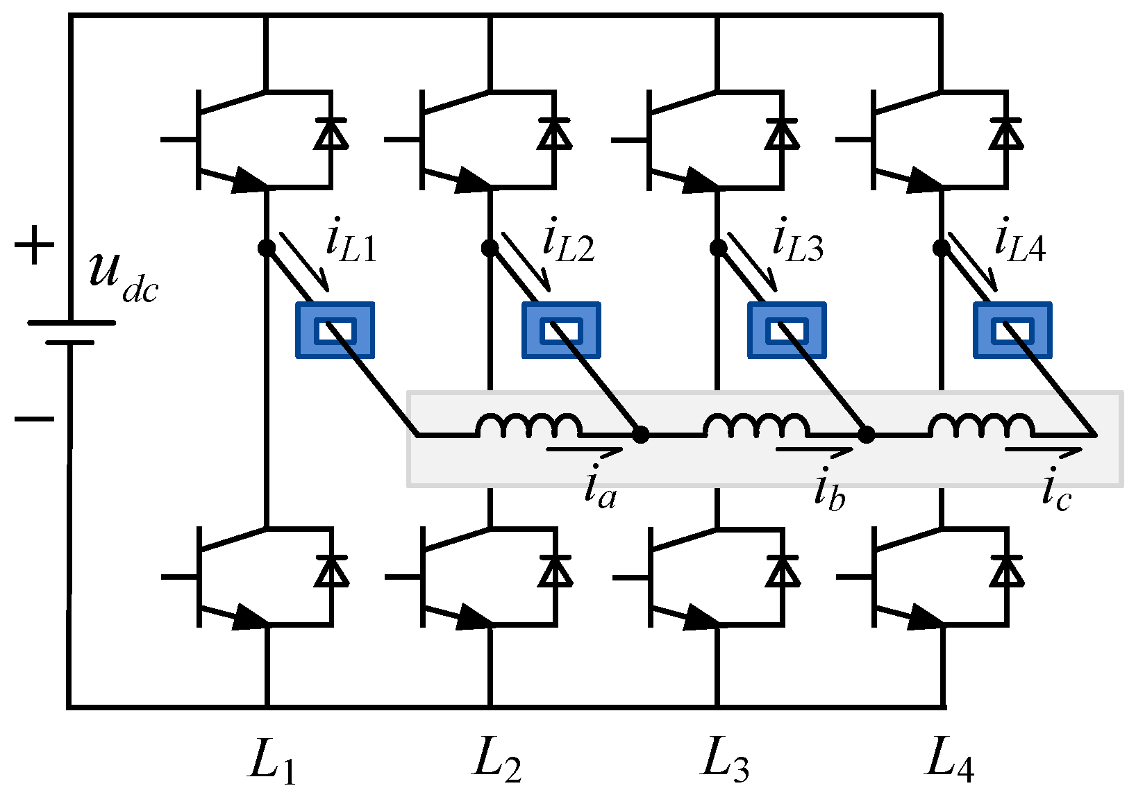
19]. However, since the current sensors are typically integrated with the HBPMs, the feedback information from the current sensors are the leg currents of the inverter, not the phase currents of the motor windings, due to the series-winding topology, as depicted in
Figure 4. Thus, the phase currents of the motor windings should be reconstructed based on the leg currents of the inverter for a series-winding-topology-driven PMSM system.
On the aforementioned points, this paper proposes a DBPCC scheme for a three-phase series-winding PMSM (TPSW-PMSM) drive with HBPM-based inverter. Firstly, in
Section 1, the mathematic model of TPSW-PMSM is built, and the zero-sequence loop is taken into consideration especially. It provides the deadbeat controller with a reference voltage calculation basis in different subspaces. Secondly, the voltage vector distribution of TPSW-PMSM is studied in
Section 2. The space vector modulation strategy in different subspaces could be designed according to this. Thirdly, the phase current reconstruction strategy is derived based on the leg currents of the inverter in
Section 3. Subsequently, the DBPCC scheme for TPSW-PMSM is proposed on the basis of the above research work in
Section 4. Finally, in
Section 5, both simulation and experimental results are conducted to verify the feasibility and effectiveness of the proposed DBPCC scheme for TPSW-PMSM.
2. Mathematic Model for TPSW-PMSM
The mathematical model of TPSW-PMSM will be discussed in this section. Such a mathematical model is the basis of the reference voltage calculation in deadbeat control. The main point is the model of the zero-sequence loop. Since the third harmonic back-electromotive force of the PMSM would generate a zero-sequence current in a zero-sequence loop, the zero-sequence loop should be well handled.
As shown in
Figure 2 and
Figure 3, the topology of the TPSW-PMSM drive and the corresponding zero-sequence loop are presented. The mathematic model of TPSW-PMSM is similar to the counterpart of the three-phase open-winding PMSM as presented. Thus, the stator voltage equation in the
a-b-c stationary co-ordinate system could be expressed as:
where
u,
i, and
ψ denote the phase voltage, the phase current, and the stator flux linkage, respectively. Subscripts
a,
b, and
c denote the three-phase windings of TPSW-PMSM. Meanwhile
Rs denotes the stator resistance.
As mentioned above, due to the existence of the third harmonic back-electromotive force, the stator flux equation could be written as:
where
Ls and
Lm are the self and mutual inductances, respectively.
ψf and
ψf3 are the fundamental and third harmonic rotor flux. Meanwhile,
θe is the rotor electrical angle.
According to the Clark and Park transformation [
5], the stator voltage equation could be transferred into a
d-
q-0 synchronous rotating co-ordinate system:
where subscripts
d,
q, and 0 denote the
d-axis,
q-axis, and 0-axis components.
u0 = (
ua +
ub +
uc)/3,
i0 = (
ia +
ib +
ic)/3. Meanwhile,
ωe denotes the rotor electrical angle speed.
After the discretization of (3), it could be utilized to calculate the reference voltages in different subspaces.
3. Voltage Vector Distribution for TPSW-PMSM
The voltage vector distribution of TPSW-PMSM is studied in this section. The space vector modulation strategies of different subspaces could be designed according to this voltage vector distribution study. Different from the conventional star-winding topology, there exists a zero-sequence loop in series-winding topology. Thus, each voltage vector contains an α-β subspace component and zero-sequence component simultaneously.
As depicted in
Figure 2, TPSW-PMSM is driven by the four-leg (four-HBPM) inverter, and there are 2
4 = 16 switching states [
SL1,
SL2,
SL3,
SL4]. Thus, the stator phase voltage could be derived from the switching states of the four-leg inverter:
where
SL = 1 means that the upper-leg switching device is turn-on, while the lower one is turn-off;
SL = 0 means the opposite condition.
udc denotes the DC-link voltage.
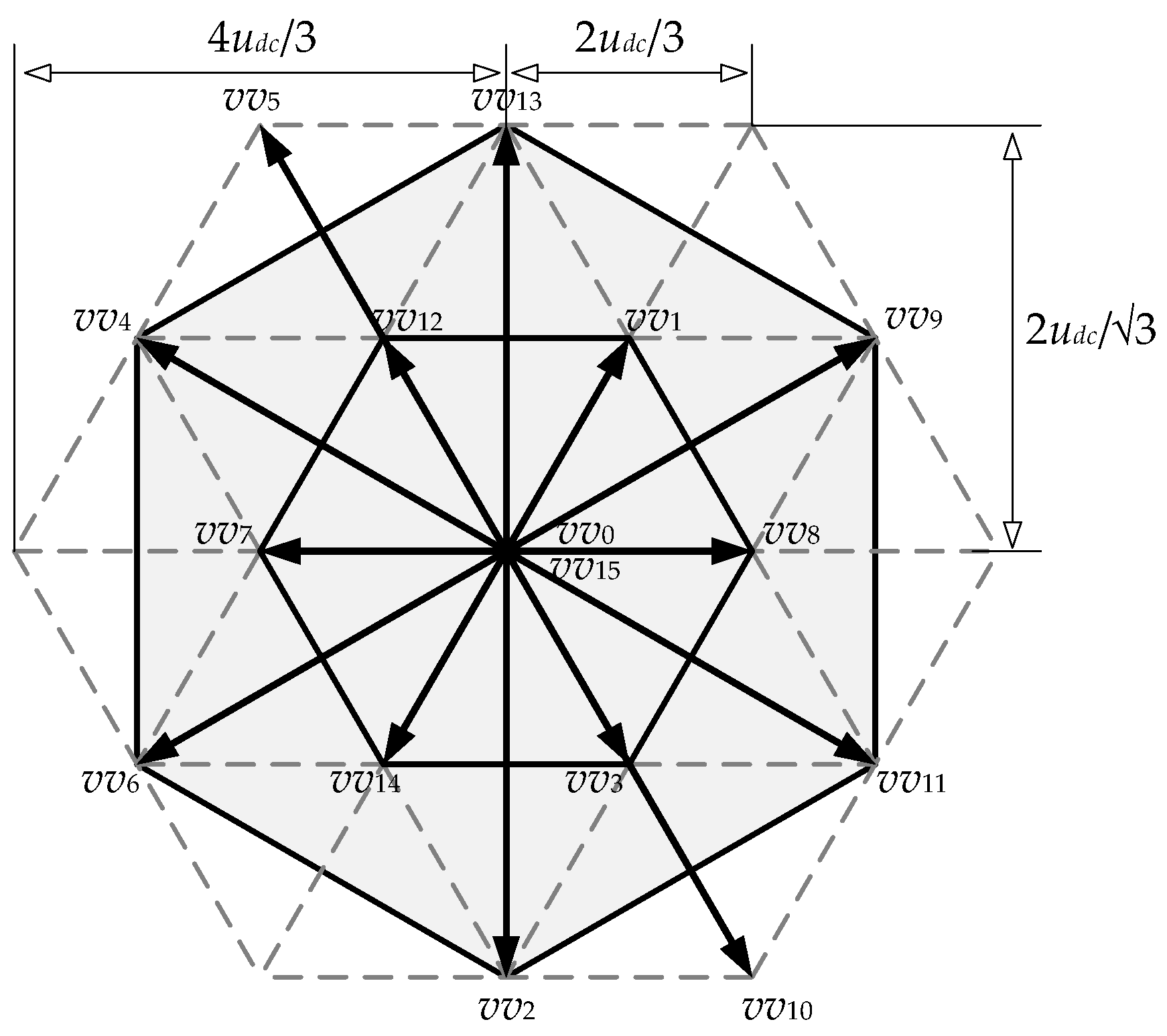
The 16 different switching states correspond to 16 voltage vectors, and they could be mapped into
α-β subspace and zero-sequence based on the Clark transformation [
5]. The subscripts number of voltage vectors represents the switching state of the inverter. For instance, switch state 0101 could be expressed as 5, which is the decimal expression of the binary numbers corresponding to the switch states. The distribution of the 16 voltage vectors in
α-β subspace is presented in
Figure 5; there are a total of 14 active voltage vectors and 2 zero voltage vectors (
vv0 and
vv15). Meanwhile, six active voltage vectors (
vv2,
vv4,
vv6,
vv9,
vv11, and
vv13), whose amplitude is 2
udc/√3, are located at the vertices of the outer hexagon. Another six active voltage vectors (
vv1,
vv3,
vv7,
vv8,
vv12, and
vv14), whose amplitude is 2
udc/3, are located at the vertices of the inner hexagon. Meanwhile, there are two additional long voltage vectors (
vv5 and
vv10), whose amplitude is 4
udc/3.
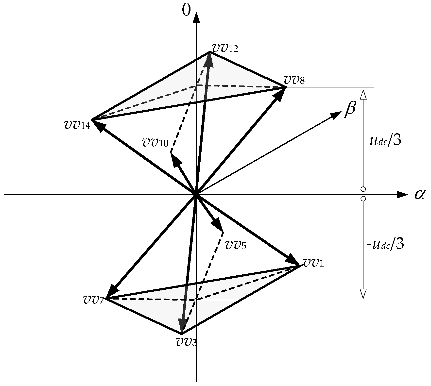
It is worth noting that the zero-sequence components of the active voltage vectors located at the outer hexagon and the zero voltage vectors are zero. Furthermore, the zero-sequence component of
vv1,
vv3,
vv5, and
vv7 is −
udc/3. Meanwhile, the zero-sequence component of
vv8,
vv10,
vv12, and
vv14 is
udc/3. In order to show the zero-sequence component of the voltage vectors more clearly,
Figure 6 depicts the voltage vectors (with a non-zero zero-sequence component) distribution in the
α-β-0 co-ordinate system.
4. Phase Current Reconstruction
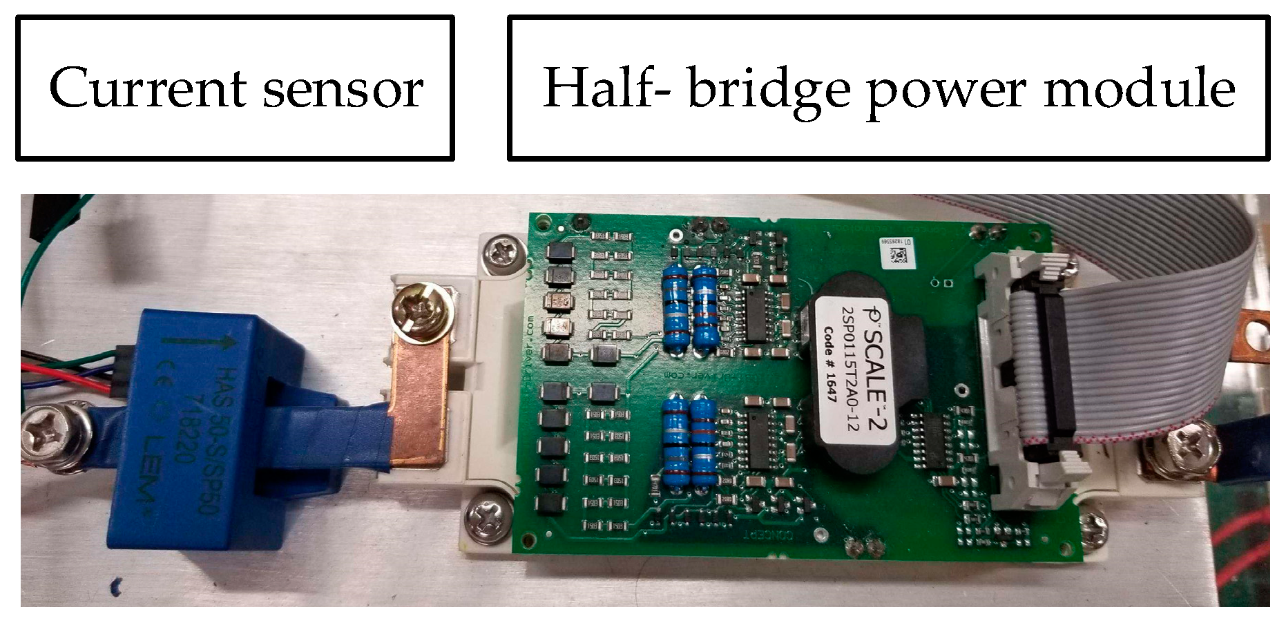
In this section, the phase current reconstruction strategy is discussed. The power devices are typically HBPMs, and the current sensors are integrated with the HBPMs, as shown in
Figure 7. Moreover, a drive circuit board is installed on the HBPM. Thus, the feedback information of the current sensors is all leg currents of the inverter. In conventional star-winding motor drives, such leg currents are the phase currents of the motor. However, in series-winding-topology-driven PMSM systems, such leg currents obtained from the current sensors (blue hollow blocks in
Figure 4) are not the phase currents of the motor windings, as shown in
Figure 4. Therefore, the three-phase currents should be reconstructed based on these four-leg currents for the TPSW-PMSM drive.
According to the topology in
Figure 4, the leg currents are
iL1,
iL2,
iL3, and
iL4, while the phase currents are
ia,
ib, and
ic, respectively. Based on the Kirchhoff’s current law, their relationship could be expressed as:
Based on Equation (5), the phase currents of the motor windings could be reconstructed for the TPSW-PMSM drive. Actually, since the three-phase currents are reconstructed from four-leg currents, the one-leg current is redundant. Thus, the phase currents could also be expressed as:
Both Equations (5) and (6) could be utilized to reconstruct the phase currents. On the basis of the leg currents from the current sensors, the phase currents of the motor windings are reconstructed for the calculation of the controller. In the experimental performance section, such a phase current reconstruction strategy is also applied.
5. Proposed Deadbeat Predictive Current Control for TPSW-PMSM Drive
The DBPCC scheme for the TPSW-PMSM drive is proposed in this section. First, according to the concept of deadbeat control, the reference voltages in
α-β subspace and zero-sequence subspace (loop) are calculated based on the mathematic model of TPSW-PMSM presented in
Section 1. Second, the space vector modulation strategies of
α-β subspace and zero-sequence subspace are designed according to the voltage vector distribution in
Section 2. The modulations of the two subspaces would not affect each other, since their modulation voltage vectors only contain the corresponding subspace components. Third, the switching pulses are generated based on the centrosymmetric principle. Further, phase current reconstruction in
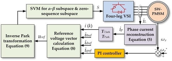
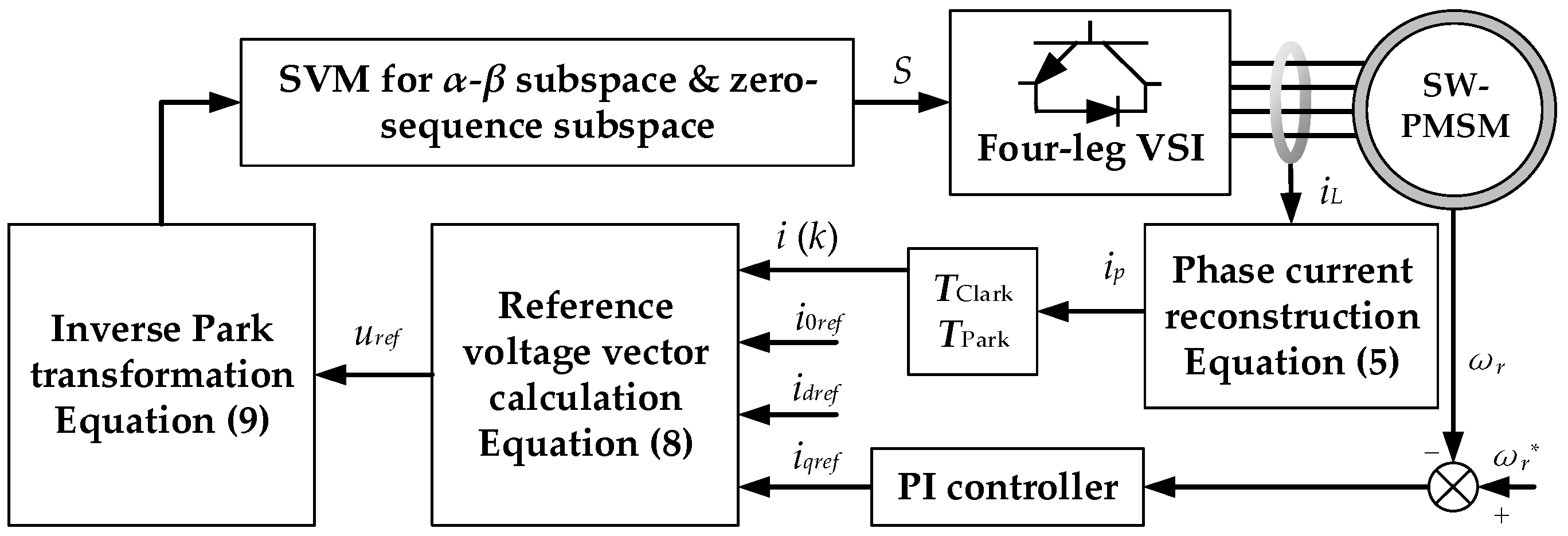
Section 3 is adopted for reference voltage calculation. The overall block diagram of the proposed DBPCC for the TPSW-PMSM drive is revealed in
Figure 8.
5.1. Reference Voltage Calculation
Above all, the reference voltages of
α-β subspace and zero-sequence subspace are calculated according to the mathematical model in
Section 1. When the forward Euler discretization method is employed, Equation (3) could be rewritten as:
where
k denotes the
kth instant, and
k + 1 denotes the (
k + 1)th instant. Meanwhile
Ts is the sampling period.
To calculate the reference voltages, we can set the currents at (
k + 1)th instant equal to the reference current, which could be denoted as
idref,
iqref, and
i0ref. Thus, the reference voltages in
d-
q subspace and zero-sequence subspace could be derived as:
After that, the reference voltages in
α-
β subspace and zero-sequence subspace could be calculated based on inverse Park transformation:
Further, the angle between the reference voltage vector and the α-axis in
α-
β subspace is defined as:
5.2. Space Vector Modulation in Different Subspaces
Since the reference voltages are obtained, we also need to design the corresponding space vector modulation strategies to track them. However, the space vector modulation in TPSW-PMSM is quite different from the counterpart of the conventional star-winding topology, because both α-β subspace and zero-sequence subspace exist in the motor windings. The modulation of different subspaces might affect each other. Thus, we should design a modulation strategy that could realize different subspace modulation decoupling.
At first, we can focus on the
α-
β subspace, since it provides the useful torque output. Based on the voltage vector distribution of TPSW-PMSM studied in
Section 2, we can find that the voltage vectors located at the outer hexagon have null-zero-sequence components, and these voltage vectors have the 2
udc/√3 amplitude. Therefore, these six voltage vectors are very suitable for
α-
β subspace modulation, thanks to their large amplitude and null-zero-sequence components.
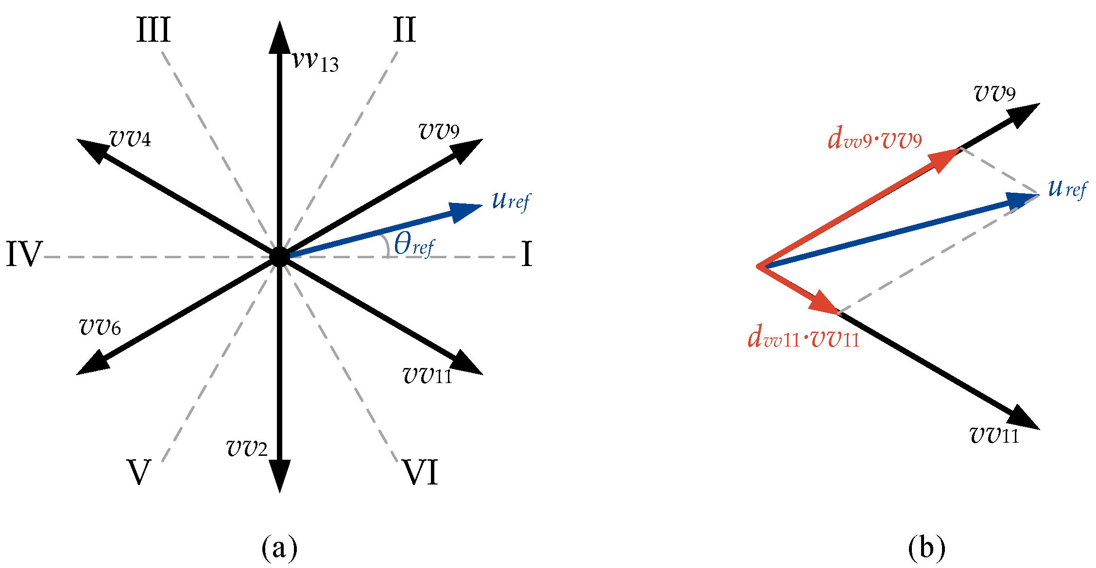
For the detail modulation process, these six voltage vectors divide the whole
α-
β subspace into six different sectors. They are marked as sector I–sector VI, respectively, as shown in
Figure 9a. Equation (10) expresses which sector the reference voltage falls in, and which two active voltage vectors should be used to modulate. Assuming the reference voltage vector falls in sector I, as depicted in
Figure 9b,
vv9 and
vv11 are employed to modulate. Their duration time in one sampling period should satisfy:
where
dvv9 denotes the duration time of
vv9 in one sampling period, and
dvv11 denotes the duration time of
vv11 in one sampling period.
The rest time of the sampling period should be the duration time of the zero voltage vectors (zero-sequence subspace modulation has not been considered yet). In addition, the reference voltage vector in α-β subspace could be tracked precisely.
Next, zero-sequence subspace should be taken into consideration. We still want to find some voltage vectors, which only contain zero-sequence components, to modulate in zero-sequence subspace and would not affect the modulation in
α-
β subspace. Due to the one-dimensional nature of the zero-sequence space, we only need two voltage vectors containing zero-sequence components in opposite directions. This could satisfy the modulation of the zero-sequence space. However, in
Figure 5 and
Figure 6, we could not find such voltage vectors. Voltage vectors with zero-sequence components all contain
α-
β components, which makes it impossible to modulate in zero-sequence subspace with only two voltage vectors.
Alternatively, we could promote the concept of the synthetic voltage vector in the literature [
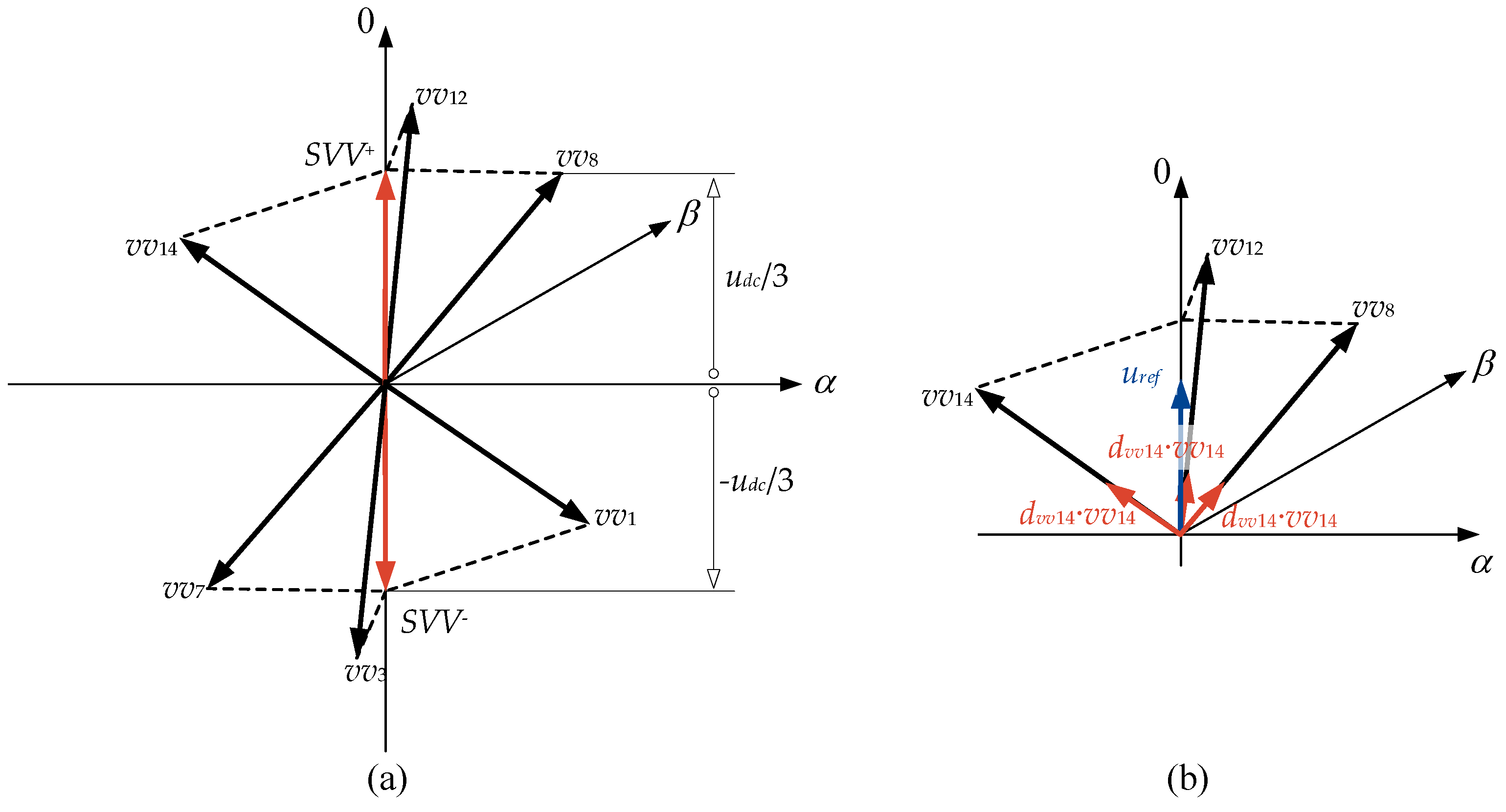
20] to the zero-sequence subspace modulation. As depicted in
Figure 6,
vv8,
vv12, and
vv14 have the same zero-sequence components. More importantly, if their duration time in one sampling period remains the same, their synthetic voltage vector will have null
α-
β component. Meanwhile, the zero-sequence component of the synthetic voltage vector is still
udc/3. This synthetic voltage vector could be denoted as
SVV+. In a similar manner,
vv1,
vv3, and
vv7 could also synthesize a voltage vector with −
udc/3 zero-sequence component and null
α-
β component, which could be denoted as
SVV−.
As shown in
Figure 10a, these two synthetic voltage vectors have the zero-sequence components in opposite directions and null
α-
β component, which indicates that they are suitable for the zero-sequence subspace modulation. Assuming the reference voltage of zero-sequence has the positive value,
SVV+ is employed to modulate. The duration time of
SVV+ in one sampling period should satisfy:
Further, it means that
vv8,
vv12, and
vv14 should be utilized, as presented in
Figure 10b. Their duration time in one sampling period should satisfy:
5.3. Switching Pulses Generation
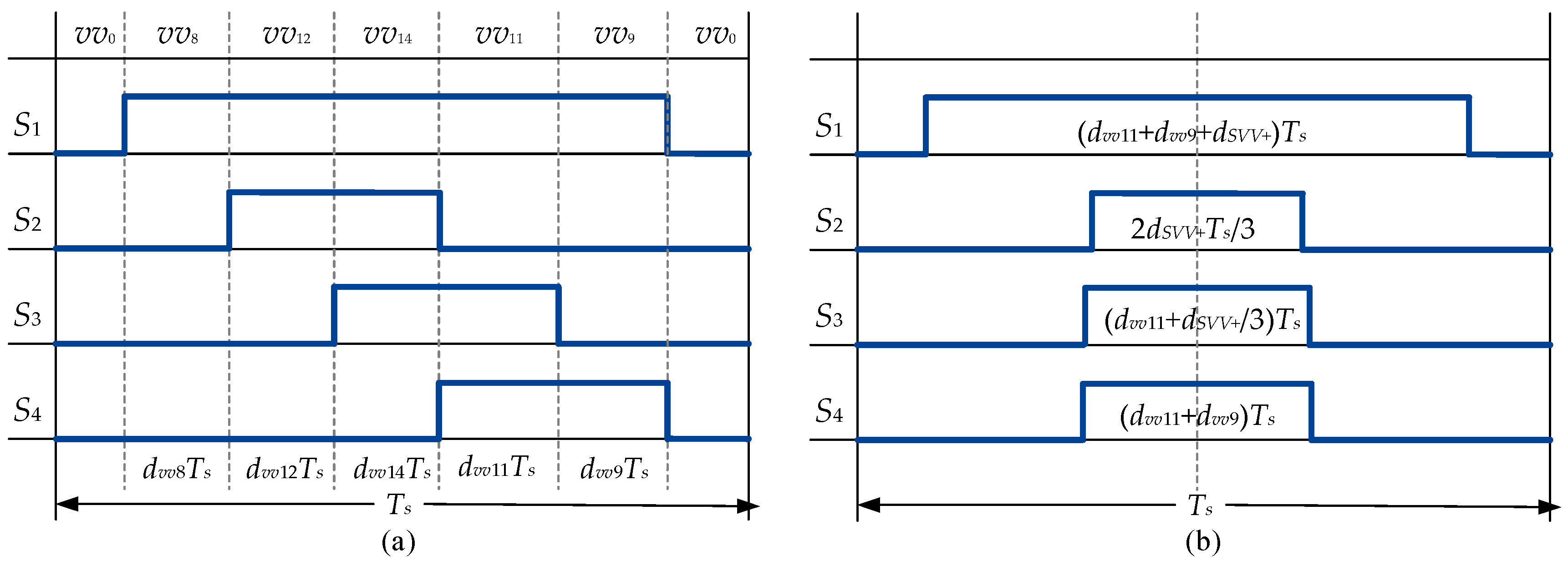
Since the duration time of the active voltage vectors in different subspaces are determined, we could obtain the switching pulses of the four-leg inverter, under the assumption that
vv9,
vv11, and
SVV+ are selected as the active voltage vectors in
α-β subspace and zero-sequence subspace, respectively. Accordingly,
SVV+ is synthesized by
vv8,
vv12, and
vv14. We could combine the active voltage vectors and their duration time in one sampling period directly; thus, we could obtain the original switching sequences that are depicted in
Figure 11a.
However, such switching sequences are asymmetrical and difficult to implement. Therefore, we can rearrange the switching sequence to be symmetrical during one sampling period, and keep the duty ratio of each leg unchanged, as shown in
Figure 11b. Hence, it could be simply implemented using the concept of carrier-based pulse-width modulation.
5.4. Overall Process of the Proposed DBPCC Scheme
As depicted in
Figure 8, the overall process of the proposed DBPCC scheme for the TPSW-PMSM drive is presented. Firstly, the phase currents of the motor are reconstructed based on the leg currents of the inverter. Then, the Clark transformation and Park transformation are employed to transfer the phase currents into a
d-
q-0 co-ordinate system. Subsequently, based on the feedback currents and the reference currents, the reference voltages for different subspaces are calculated according to Equations (8) and (9). Next, the space vector modulation strategies in different subspaces would track the reference voltages and generate the switching pulses for the HBPMs, so as to finish the action in one sampling period.
6. Simulation Study
The simulation model of the TPSW-PMSM drive system is established in MATLAB/Simulink software. Notably, the zero-sequence loop is added to the simulation model, including the third harmonic back-electromotive force and the zero-sequence inductance. The TPSW-PMSM parameters are listed in
Table 1. The simulation period is set to 1 μs, and the sampling period is set to 50 μs, which means the sampling frequency is 20 kHz. The bus voltage is set to 20 V.
First, the zero-sequence current suppression performance of the proposed scheme under steady-state is observed. As a comparison, the simulation without zero-sequence current suppression is also conducted. It means the zero-sequence loop is not controlled, and the other parts of the control scheme are the same as the proposed scheme.
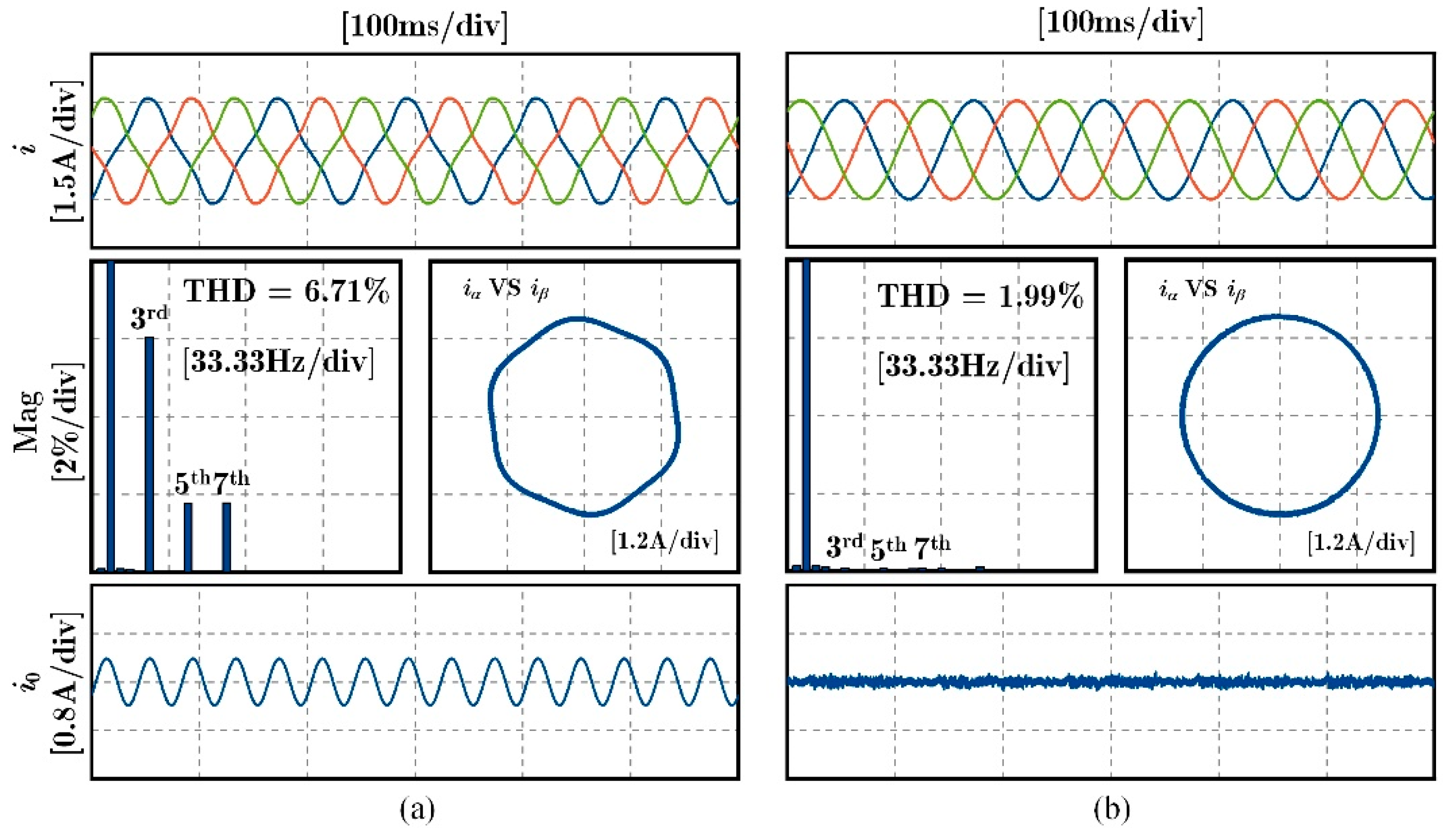
Figure 12 shows the current performance of the proposed scheme and the comparison scheme under 100 r/min and 2.5 N∙m, including the currents in
α-β subspace and zero-sequence subspace. From
Figure 12a, it can be found that, without the control of the zero-sequence loop, the zero-sequence current amplitude reaches 0.4 A, which is mainly caused by the third harmonic rotor flux linkage. It greatly affects the steady-state performance of the system. The total harmonic distortion (THD) degrades to 6.71%, and the corresponding third harmonic wave amplitude reaches 6% of the fundamental wave. While the proposed scheme is employed, the zero-sequence loop is under control. Thus, the zero-sequence current is suppressed well. From
Figure 12b, it can be found that the zero-sequence current amplitude is under 0.1 A, which indicates the third harmonic back-electromotive force from the harmonic rotor flux linkage is canceled out by the zero-sequence component of the voltage vectors (
SVV+ and
SVV−). Meanwhile, the THD level is 1.99%, and the corresponding third harmonic wave amplitude is much smaller than the counterpart of the comparison scheme. Thus, the steady-state performance initially testifies the correctness of the proposed DBPCC scheme for TPSW-PMSM.
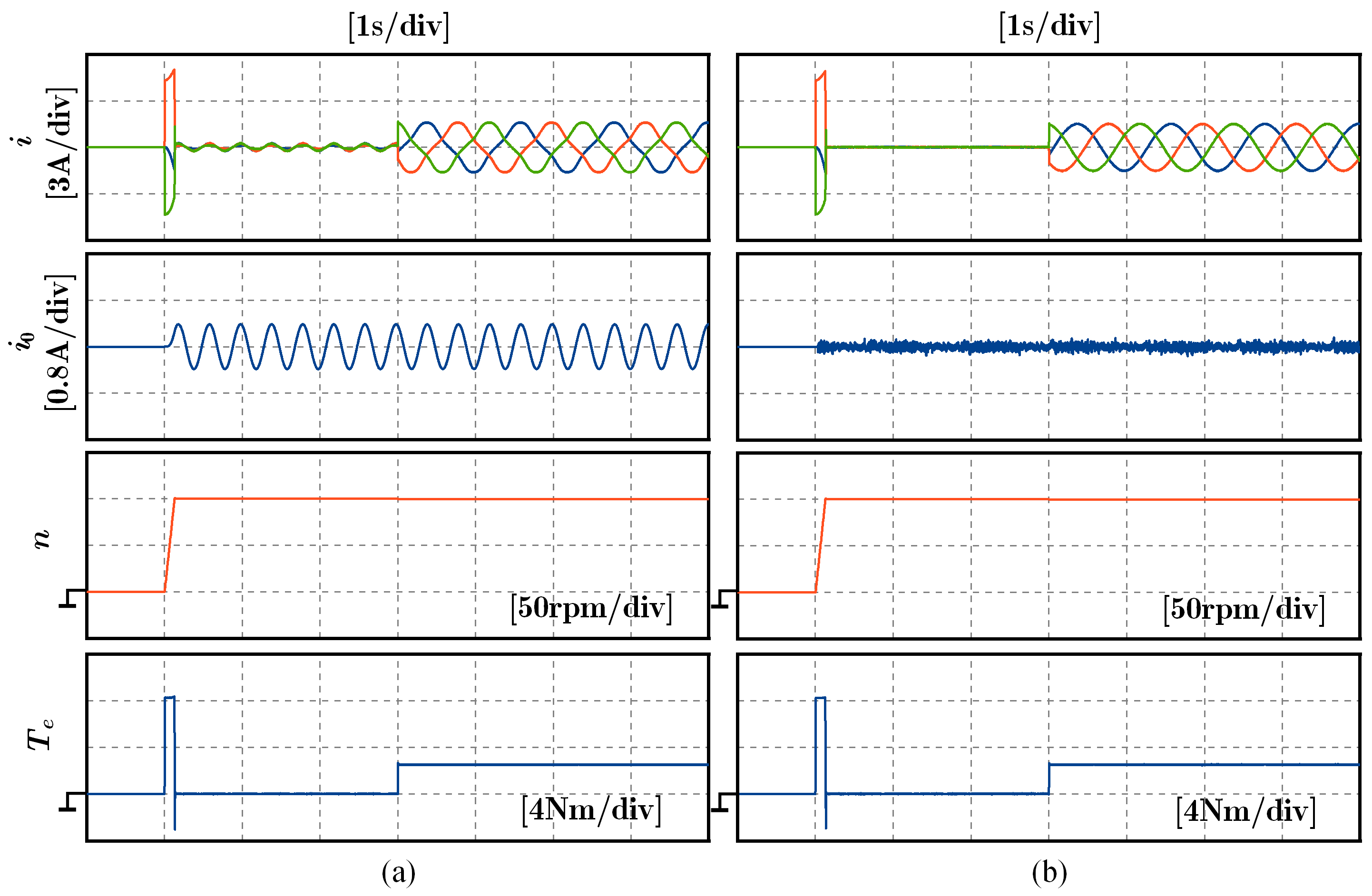
Second, to verify the dynamic performance of the proposed scheme for TPSW-PMSM, a dynamic test with speed change and torque change is conducted, as shown in
Figure 13. In a similar manner, a comparison scheme without zero-sequence loop control is also conducted. During the whole dynamic process, at 1 s, the speed is set to 100 r/min without any load. After the speed is stable, a 2.5 N∙m load is added at 4 s. The suppression of the zero-sequence current is observed. Moreover, as revealed in
Figure 13a, without the zero-sequence loop control, the zero-sequence current amplitude is around 0.4 A during the dynamic process. However, things are much different when the proposed scheme is adopted, the zero-sequence current is suppressed well during the dynamic process, as presented in
Figure 13b. Therefore, it can be concluded that the proposed DBPCC scheme for TPSW-PMSM can effectively suppress the zero-sequence current in simulation.
7. Experimental Results
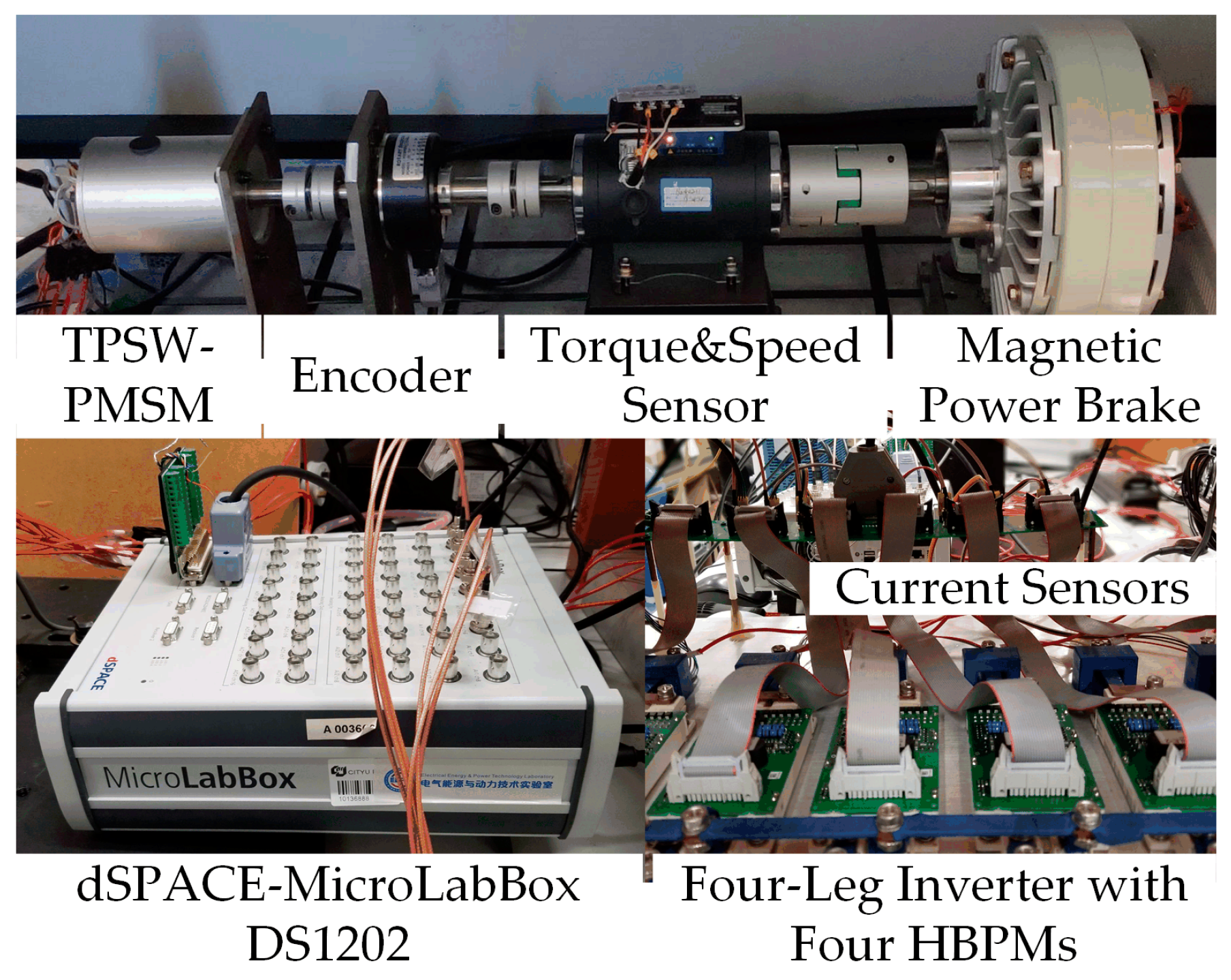
Experiments in this section verify the feasibility and effectiveness of the proposed DBPCC scheme for the TPSW-PMSM drive with HBPM-based inverter. The overall experimental testbed configurations are shown in
Figure 14, and their models are listed in
Table 2. The parameters of the TPSW-PMSM are listed in
Table 1, which are the same as the simulation study. Such electrical parameters are obtained by LCR meter and inverter supply test. The back EMF of the FP-PMSM is tested by a servo motor. The PMSM is loaded with a magnetic powder brake. The current measurement is taken with hall-effect sensors (HAS 50-S). The sampling frequency is also set to 20 kHz, and the bus voltage is 20 V.
As mentioned in
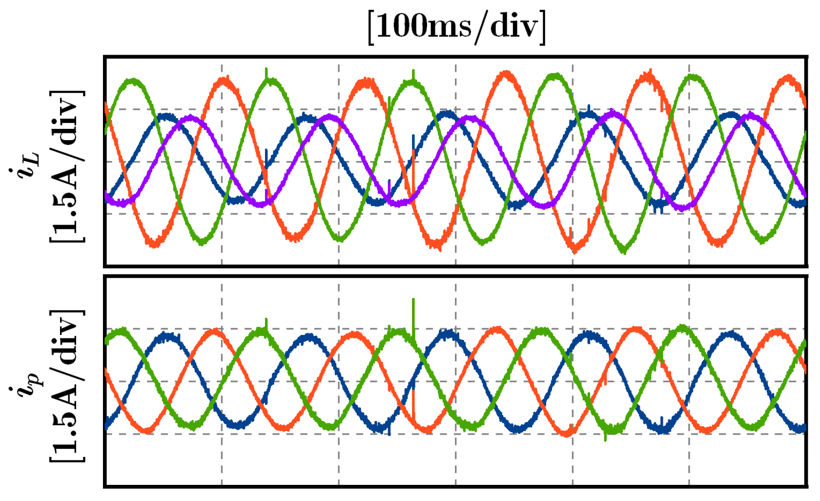
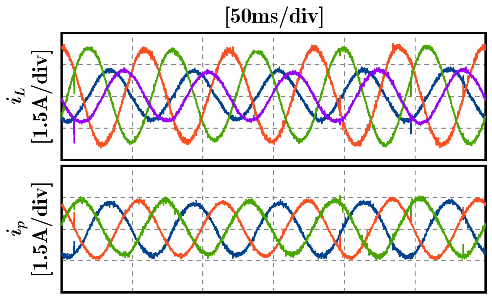
Section 3, the current sensors are integrated with the HBPMs. Thus, the phase current reconstruction strategy is verified first. The four-leg currents are measured from the current sensors and sent to the dSPACE. According to Equation (5), the three-phase currents are reconstructed from the four-leg currents. Then, they are fed back to the controller for the following reference voltage calculation. As shown in
Figure 15 and
Figure 16, the phase current reconstruction strategy is tested under 100 rounds per minute (r/min) and 200 r/min with 2.5 N∙m load, respectively. Meanwhile, the proposed DBPCC scheme is adopted (it will be further tested in the following experiments). It can be seen that the leg currents of the four HBPMs are not balanced. Since the first HBPM (
L1) and the last HBPM (
L4) only undertake one-phase current, while the middle two HBPMs (
L2 and
L3) undertake two-phase currents, the middle two-leg currents are larger than the other two-leg currents. Subsequently, the reconstructed phase currents are shown below. The three-phase currents are balanced under different speeds. Such phase currents are directly sent to the DBPCC controller for reference voltage calculation, and the current performance is good, which indicates that the phase current reconstruction strategy is correct.
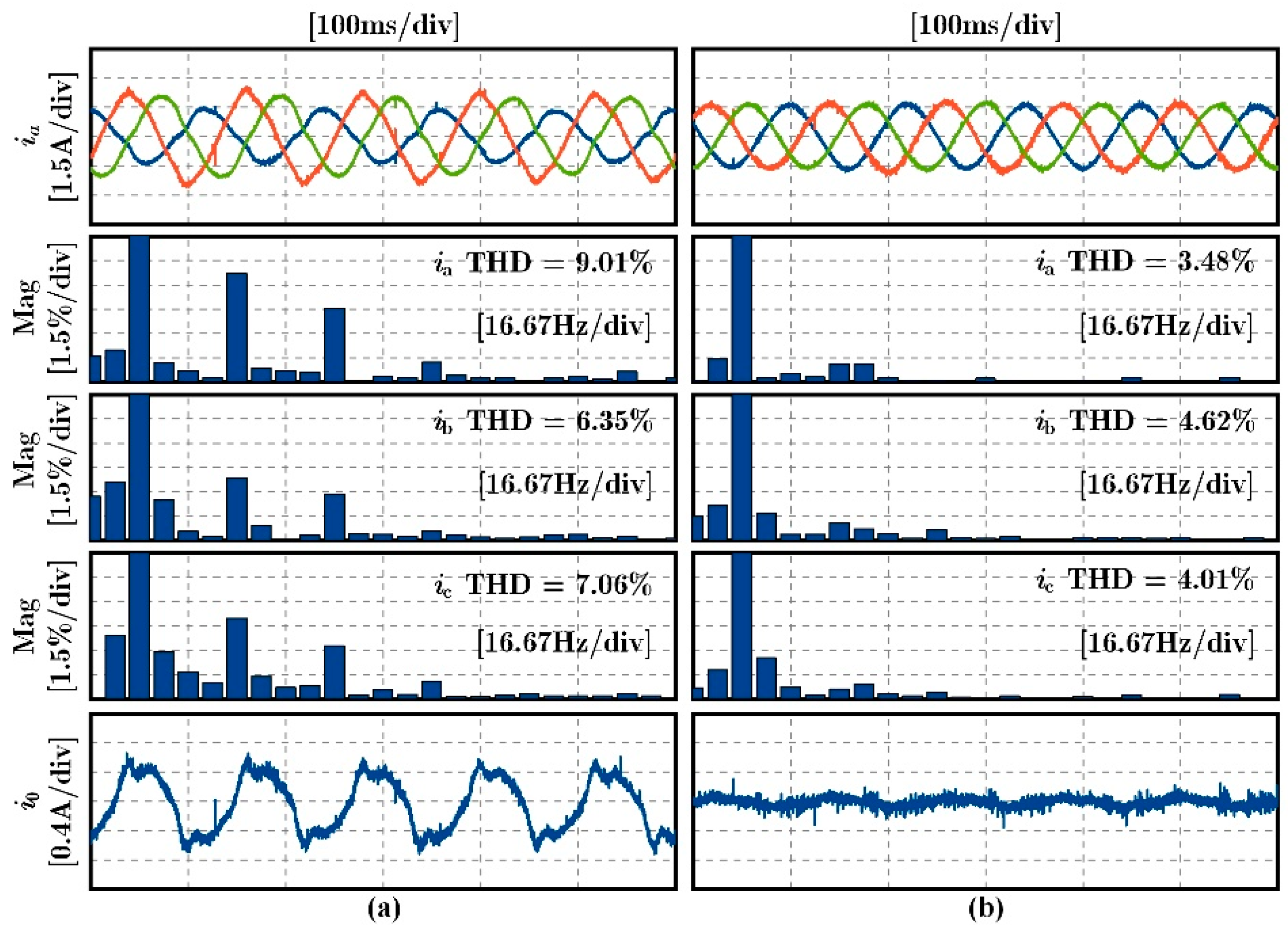
Moreover, the zero-sequence current suppression performance of the proposed DBPCC scheme is verified by steady-state experiments. Similar to the simulation study, a comparison scheme without zero-sequence loop control is employed as the control experiment. In addition, the phase current reconstruction strategy is also employed here to get the phase currents from the leg currents. In
Figure 17, the speed is set to 100 r/min, and the load is 2.5 N∙m. If the zero-sequence loop is not controlled, as shown in
Figure 17a, the zero-sequence current amplitude is around 1.2 A, even leading to the unbalance of the three-phase currents. Thus, to measure the current performance, the THD of every phase current is tested and presented below. The THD level of the comparison scheme has a range from 7.06 to 9.01%. Moreover, the corresponding third harmonic wave amplitude is large, which ranges from 4.5 to 7% of the fundamental wave amplitude.
Once the proposed scheme is adopted, the zero-sequence loop is under control. As shown in
Figure 17b, the zero-sequence current is suppressed well. In addition, the THD level is from 3.48 to 4.01% thanks to the active zero-sequence loop control. As a result, the corresponding third harmonic wave is also suppressed. This can illustrate the effectiveness of the proposed scheme.
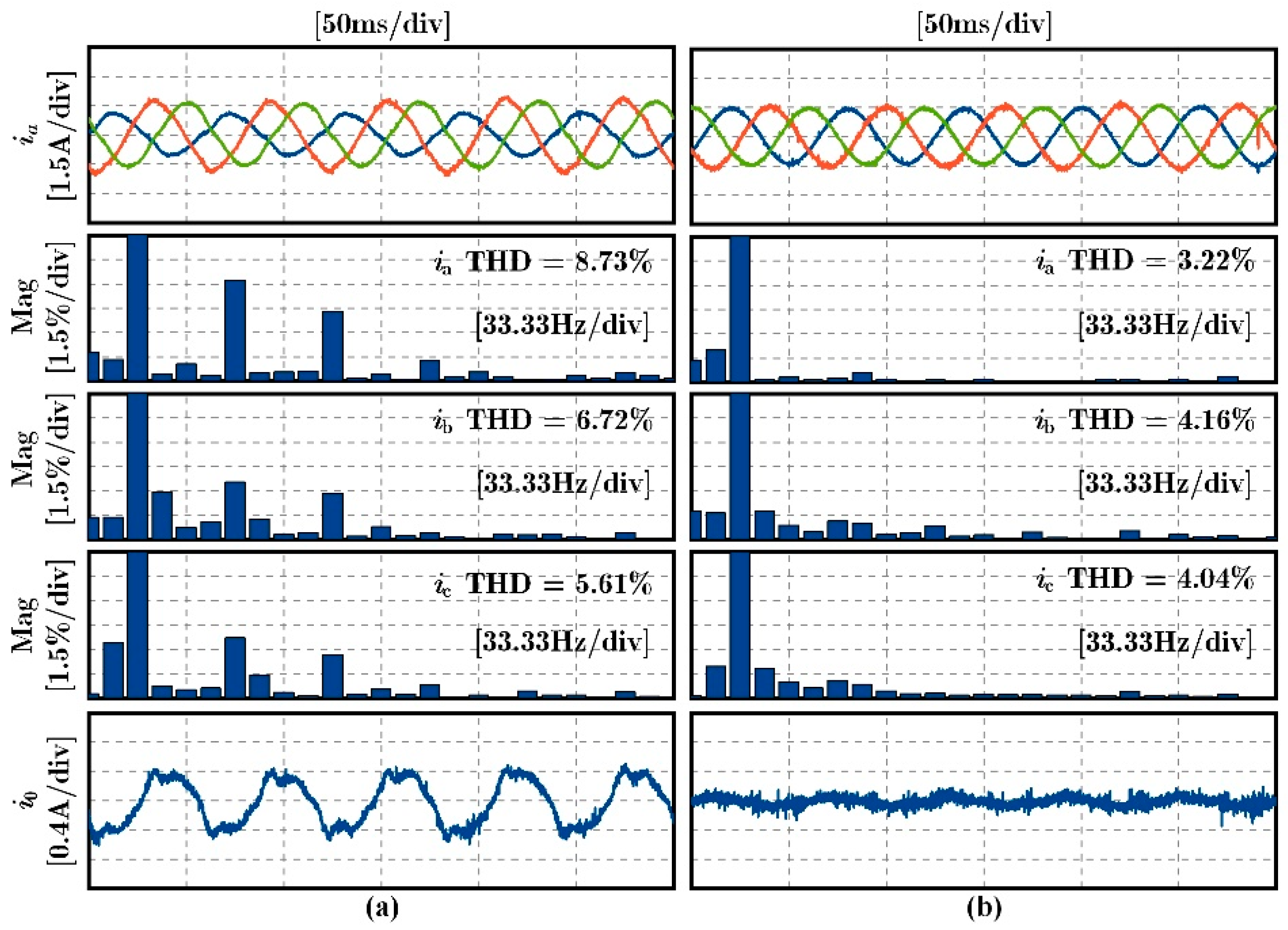
The same conclusion could also be drawn from the experimental results under 200 r/min steady-state operation, as shown in
Figure 18. Without the zero-sequence current suppression, the THD level of the phase currents has a range from 5.61 to 8.73%. Meanwhile, the zero-sequence current ripple is around 1 A. After the zero-sequence current is suppressed, the THD level of the phase currents decreases to about 4%, while the zero-sequence current ripple is suppressed to 0.4 A. Therefore, we can find that the proposed DBPCC scheme is suitable for the TPSW-PMSM drive. Since the phase currents could be reconstructed from the leg currents, and the zero-sequence current could also be suppressed well, this provides better performance for the drive system.
8. Conclusions
The three-phase series-winding PMSM drive with half-bridge power-module-based inverter suffers from the additional zero-sequence current. Meanwhile, the phase current could not be obtained directly, since the current sensors are integrated with the half-bridge power modules. To deal with the aforementioned problems, the main contributions of this paper are summarized as follows:
(1) The mathematic model of the three-phase series-winding PMSM, including the zero-sequence subspace, is built. It provides the deadbeat controller with the basis of the reference voltage calculation in α-β subspace and zero-sequence subspace.
(2) The space vector modulation strategy of α-β subspace and zero-sequence subspace is proposed. The reference voltage could be tracked accurately. More importantly, the modulation in different subspaces would not affect each other, since the synthetic voltage vector is employed in zero-sequence subspace modulation.
(3) The phase current reconstruction strategy is proposed. Based on the leg currents from the current sensors, the phase current could be reconstructed for the further calculation of the controller.
Therefore, the deadbeat predictive current control scheme is proposed based on the above works. Since the phase currents are reconstructed and the zero-sequence current is suppressed, the THD level is reduced from around 8 to 4%, and the zero-sequence current ripple is suppressed from 1 to 0.4 A. The proposed scheme could provide the three-phase series-winding PMSM drive with a half-bridge power-module-based inverter with better performance.


